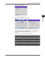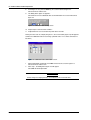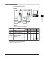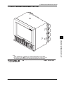
1
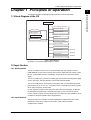
Service
Manual
Yokogawa Electric Corporation
DAQSTATION
DX100/DX200
SM 04L01A01-01E
4th Edition
Important Notice To the User
This manual contains information for servicing the YOKOGAWA DAQSTATION DX100/
DX200. Check the serial number to confirm that this service manual corresponds to your
instrument. Make sure not to use the wrong manual.
Before any maintenance and servicing, read all safety precautions carefully.
Only properly trained personnel may carry out maintenance and servicing in accordance
with and to the extent permitted by this service manual.
Do not disassemble the instrument or its parts, unless otherwise clearly permitted by this
service manual.
Do not replace any part or assembly, unless otherwise clearly permitted by this service
manual.
Yokogawa Electric Corporation (YOKOGAWA) does not in principle supply parts other
than those listed in the customer maintenance parts list in this service manual (mainly
modules and assemblies). Therefore if an assembly fails, the user should replace the
whole assembly and not components within the assembly (see NOTE). If the user
attempts to repair the instrument by replacing individual components within the
assembly, YOKOGAWA assumes no responsibility for any consequences, such as
defects in instrument accuracy, functionality, or reliability, or user safety hazards.
YOKOGAWA does not offer more detailed maintenance and service information than that
contained in this service manual.
All reasonable efforts have been made to assure the accuracy of the content of this
service manual. However, there may still be errors such as clerical errors or omissions.
YOKOGAWA assumes no responsibility of any kind concerning the accuracy or contents
of this service manual, nor for the consequences of any errors.
All rights reserved. No part of this service manual may be reproduced in any form or by
any means without the express written prior permission of YOKOGAWA. The contents of
this manual are subject to change without notice.
Note
YOKOGAWA instruments have been designed in a way that the replacement of electronic parts
can be done on an assembly (module) basis by the user. YOKOGAWA instruments have also
been designed in a way that troubleshooting and replacement of any faulty assembly can be
done easily and quickly. Therefore, YOKOGAWA strongly recommends replacing the entire
assembly over replacing parts or components within the assembly. The reasons are as follows:
• The instruments use high-performance microprocessors, large scale CMOS gate arrays and
surface-mount components to provide state-of-the-art performance and functions.
• Repair of components can only be performed by specially trained and qualified maintenance
personnel with special highly-accurate tools, including costly ones.
• When taking the service life and cost of the instruments into consideration, the replacement of
assemblies offers the user the possibility to use YOKOGAWA instruments more effectively
and economically with a minimum in downtime.
• Zip is a trademark or registered trademark of Iomega Corporation in the United States
and/or other countries.
• Adobe and Acrobat are trademarks of Adobe Systems incorporated.
4th Edition : June 2010 (YK)
All Rights Reserved, Copyright © 2000, Yokogawa Electric Corporation
SM 04L01A01-01E
1
Introduction
This manual contains information for servicing the YOKOGAWA DAQSTATION DX100/
DX200.
Note
This is the third edition of the manual, dated August 2007.
WARNING
This service manual is to be used by properly trained personnel only. To avoid
personal injury, do not perform any servicing unless you are qualified to do so.
Refer to the Safety Precautions prior to performing any service.
Even if servicing is carried out by qualified personnel according to this service
manual, YOKOGAWA assumes no responsibility for any result occurring from
this servicing.
Safety Precautions
The following general safety precautions must be observed during all phases of
operation, service, and repair of this instrument. Failure to comply with these
precautions or with specific WARNINGS given elsewhere in this manual violates safety
standards of design, manufacture, and intended use of the instrument.
YOKOGAWA ELECTRIC CORPORATION assumes no liability for the customer’s failure
to comply with these requirements.
General Definitions of Safety Symbols Used on Equipment and in Manuals
High temperature. To avoid injury caused by hot surfaces, the
operator must not touch the heatsink.
Danger. Affixed to the instrument, this symbol indicates danger to
personnel or the instrument and the operator must refer to the
user's manual. The symbol is also used in the corresponding place
in user's manual.
Protective grounding terminal,to protect against electrical shock.
This symbol indicates that the terminal must be connected to
ground before operation of equipment.
Functional earth terminal. This terminal should not be used as a
“Protective earth terminal.”
2
WARNING
Describes precautions that should be observed to prevent serious
injury or death to the user.
CAUTION
Describes precautions that should be observed to prevent minor or
moderate injury, or damage to the instrument.
SM 04L01A01-01E
WARNING
Power Supply
Ensure the source voltage matches the voltage of the power supply before
turning ON the power.
Protective Grounding
The protective earth terminal must be connected to ground to prevent an electric
shock before turning ON the power.
Necessity of Protective Grounding
Never cut off the internal or external protective earth wire or disconnect the
wiring of the protective earth terminal. Doing so poses a potential shock hazard.
Fuse
To prevent a fire, make sure to use a fuse with the specified standard (current,
voltage, type). Before replacing the fuse, turn off the power and disconnect the
power source. Do not use a different fuse or short-circuit the fuse holder.
See page 3-3 or 3-4 in chapter 3.
Defect in the Protective Earth Terminal and Fuse
Do not operate the instrument when the protective earth terminal or fuse might
be defective.
Do Not Operate New Flammable Meterials
Do not operate the instrument in the presence of flammable liquids or vapors.
Operation of any electrical instrument in such an environment constitutes a
safety hazard.
Do Not Remove Any Covers
There are some components inside the instrument containing high voltages. Do
not remove any cover if the power supply is connected. The cover should be
removed by qualified personnel only.
External Connection
To ground securely, connect the protective grounding before connecting to the
measurement or control unit. Also, before touching the circuit, turn off the power
to the circuit and check that there is no voltage being generated.
SM 04L01A01-01E
3
Overview of This Manual
This manual is meant to be used by qualified personnel only. Make sure you read the
safety precautions at the beginning of this manual and the warnings and cautions
contained in any relevangt chapters prior to carrying out servicing.
This manual contains the following chapters.
1
General Information
Provides an introduction and describes safety considerations.
2
Performance Tests
Describes the tests for checking the performance of the instrument.
3
Adjustment
Describes the adjustments which can be performed by users.
4
Principles of Operation
Function block diagrams and principles of operation.
5
Troubleshooting
Describes procedures for troubleshooting and how to handle the replacement of
parts.
6
Schematic Diagram
Contains the system configuration diagram.
7
Customer Maintenance Parts List
Contains exploded views and a list of replaceable parts.
Specifications are not included in this manual; for specifications, refer to IM
04L01A01-01E or IM 04L02A01-01E.
4
SM 04L01A01-01E
Contents
1
Important Notice To the User ...............................................................................................................1
Introduction ...........................................................................................................................................2
Safety Precautions ............................................................................................................................... 2
Overview of This Manual ......................................................................................................................4
Chapter 1
Chapter 2
Chapter 3
Principles of Operation
1.1 Block Diagram of the DX .......................................................................................................... 1-1
1.2 Input Section ............................................................................................................................. 1-1
1.2.1 A/D Assembly ............................................................................................................... 1-1
1.2.2 Input Terminal ............................................................................................................... 1-1
1.2.3 Scanner Assembly ........................................................................................................ 1-2
1.3 Data Storage Functions ............................................................................................................ 1-2
1.4 Display Unit ............................................................................................................................... 1-2
1.5 Calculation Function ................................................................................................................. 1-2
1.6 Alarm Function .......................................................................................................................... 1-2
1.7 Other Functions ........................................................................................................................ 1-2
3
Testing
6
2.1 Acceptance Test ........................................................................................................................ 2-1
2.2 Self Diagnostic Test .................................................................................................................. 2-1
2.3 Performance Test ...................................................................................................................... 2-2
2.3.1 Before You Begin .......................................................................................................... 2-2
2.3.2 Measurement Accuracy Test ......................................................................................... 2-3
2.3.3 Reference Junction Compensation Accuracy Test ....................................................... 2-4
7
Replacing Parts
3.1 Replaceable Parts .................................................................................................................... 3-1
3.2 When Repair is Necessary ....................................................................................................... 3-1
3.3 Recommended Replacement Periods for Worn Parts .............................................................. 3-2
3.4 Replacing the Fuse ................................................................................................................... 3-3
3.5 Replacing the Battery ............................................................................................................... 3-4
Chapter 4
Adjustments
4.1 Before You Begin ...................................................................................................................... 4-1
4.2 AD Board Offset and Gain Adjustment ..................................................................................... 4-2
4.2.1 Manual Adjustment ....................................................................................................... 4-2
4.2.2 PC Controlled Adjustment ............................................................................................ 4-5
Chapter 5
Troubleshooting
5.1 Procedure ................................................................................................................................. 5-1
5.2 Flow Chart ................................................................................................................................ 5-1
5.3 Troubleshooting Checklist ......................................................................................................... 5-2
Chapter 6
Chapter 7
Schematic Diagram
Customer Maintenance Parts List
7.1 DX100 Customer Maintenance Parts List ................................................................................. 7-1
7.2 DX100 Standard Accessories ................................................................................................... 7-8
7.3 DX200 Customer Maintenance Parts List ................................................................................. 7-9
7.4 DX200 Standard Accessories ................................................................................................. 7-16
SM 04L01A01-01E
2
5
4
5
1.1 Block diagram of the DX/1.2 Input section
Chapter 1 Principles of Operation
1
PRINCIPLE OF OPERATION
This chapter describes the principles of operation for the DX100 and DX200.
1.1 Block Diagram of the DX
CPU
Data storage functions
Input section
Input terminal
External storage
Internal memory
Scanner assembly
Display unit
A/D assembly
Calculation function
Alarm function
Communication function
Remote function
(optional)
Relay contact
(optional)
Transmitter power supply
(optional)
Figure 1 Block diagram
For datails see schematic diagram page 6-1 and 6-2.
1.2 Input Section
1.2.1 A/D Assembly
The A/D assembly has items such as a programmable gain amp, voltage reference,
PWM modulator, current source for RTD measurements, differential amp, voltage source
for RJC, serial parallel converter, control logic, and an occurred scanner SSR control
signal.
The A/D assembly uses a sinewave oscillating type self-resonant switching power supply
(DC/DC converter), and noise filtering is achieved by signal integration.
The A/D assembly detects the frequency of the power while it is ON and the integrated
time becomes 20 ms or 16.67 ms. Therefore it carries a very high rate of noise rejection
for the power frequency (in auto mode).
In case the power frequency of the instrument and of the measured object are different,
the appropriate integrated time is manually selectable. In case of the DX106, DX112,
DX210, DX220, or DX230, the selection of 100 ms for 50/60 Hz is also available. A 16 bit
resolution is achieved regardless of the integrated time.
1.2.2 Input Terminal
The input terminal is removable. The internal printboard is isothermal because a print
board with a metal core is being used. Therefore, stable reference junction
compensation is realized.
SM 04L01A01-01E
1-1
1.2 Input Section/1.3 Data Storage Functions/1.4 Display Unit/1.5 Calculation Function/1.6 Alarm Function/1.7 Other Functions
1.2.3 Scanner Assembly
An in-house SSR (solid state relay) is being used for the scanner. The SSR, having a
semiconductor switch, has a withstand voltage as high as 1500 V and a leakage current
of only 1 nA. For that reason, it has the following features.
1) Semi-infinite life due to the absence of mechanical contacts
2) Silent operation
3) No occurrence of thermoelectric power.
On the other hand, compared to a mechanical relay, the SSR has, the disadvantage of a
bigger ON resistance and OFF capacity. As a result, RTD measurement and noise
resistance characteristics are affected. Regarding RTD measurements, a differential
amp was inserted into the previously mentioned analog circuit without increasing the
number of parts, so that it would receive no influence from ON resistance.
For RTD measurements there is generally no insulation between channels.
1.3 Data Storage Functions
For storing data, the DX has 1.2 MB of internal memory and is equipped with a 3.5-inch
floppy disk drive (1.44 MB 2HD), a Zip drive, or an ATA flash memory card drive. The
measured data can also be saved to external storage media such as floppy disks, Zip
disks, and ATA flash memory cards.
1.4 Display Unit
The DX has a 5.5-inch (DX100) or 10.4-inch (DX200) TFT color LCD on which it displays
the measured results (240 (vertical) × 320 (horizontal) pixels for the DX100 or 480
(vertical) × 640 (horizontal) pixels for the DX200).
1.5 Calculation Function
The DX performs differential computation, linear scaling, and square roots using a
microprocessor on the CPU board.
1.6 Alarm Function
The following six alarm types can be set.
High limit (H), low limit (L), differential high limit (h), differential low limit (l), rate-ofchange on increase (R), rate-of-change on decrease (r), alarm delay upper limit alarm
(T), or alarm delay lower limit alarm (t).
1.7 Other Functions
1
2
3
4
1-2
Communication function:
Ethernet (standard)
RS-232/RS-422A/FOUNDATION Field bus interface added (optional).
Remote function:
The trigger, start/stop, time adjustment, and other functions can be controlled
remotely (optional).
Relay contact:
Alarm output and memory end/fail output (optional).
Transmitter power supply:
DC24 V output for transmitter (optional).
SM 04L01A01-01E
2.1 Acceptance Test/2.2 Self Dignostic Test
Chapter 2 Testing
This chapter describes the following tests.
2
2.1 Acceptance Test
This section describes the procedure to perform the acceptance test.
1
2
3
4
5
Read the preface, to the user’s manual, “Checking the Package Contents” and verify
that you have all of the contents.
Make sure to understand the operating procedures as described in the user’s
manual.
Check each function using the user’s manual.
Read and implement section 2.2, “Self Diagnostic Test.”
Read and implement section 2.3, “Performance Test.”
2.2 Self Diagnostic Test
The DX is provided with complete self diagnostic functions to enhance reliability in
measurement and serviceability.
When you turn ON the power, the DX will automatically execute the following types of
diagnoses alternately and display the results. After these tests are completed, the DX is
ready for use.
1
2
3
4
Main ROM sum test
Main RAM write/read test
A/D and A/D ROM sum test
Acquisition memory test
Table 2 shows the order and results of the self diagnostic tests.
SM 04L01A01-01E
Code
Message
901
ROM failure.
902
RAM failure.
910
A/D memory failure for all input channels.
911
Channel 1 A/D memory failure.
912
Channel 2 A/D memory failure.
913
Channel 3 A/D memory failure.
914
Channel 4 A/D memory failure.
921
Channel 1 A/D calibration value error.
922
Channel 2 A/D calibration value error.
923
Channel 3 A/D calibration value error.
924
Channel 4 A/D calibration value error.
930
Memory acquisition failure.
940
The Ethernet module is down.
2-1
PERFORMANCE TEST
2.1 Acceptance test
2.2 Self Diagnostic test
2.3 Performance test
2.3 Performance Test
2.3
Performance Test
This paragraph describes several tests to verify the operation of the DX’s performance
against published specifications.
2.3.1 Before You Begin
2.3.2 Measurement Accuracy Test
2.3.3 Reference Junction Compensation Accuracy Test
The performance tests need not be performed in any specific order.
2.3.1 Before You Begin
Testing Conditions
When carrying out the performance tests described in the following pages, make sure
the instrument is tested under the following conditions:
Ambient temperature:
23±2°C
Humidity:
55±10%RH
Power supply voltage:
90 to 132 VAC, 180 to 250 VAC
Power supply frequency:
50/60 Hz±1%
Preparation
Perform the following steps before carrying out the performance tests described in the
following pages.
1 Turn ON the power supply and verify that the DX passes the self diagnostic test
without any problems.
2 Allow a warm up time of at least 30 minutes for required instruments and the unit
under test.
Instruments Required for Tests
2-2
Instrument
Required Specifications
Recommended
DC Voltage Generator
Accuracy: ± 50ppm
FLUKE 5520A
Decade Resistance Box
Accuracy: ± 10ppm
YOKOGAWA 279301
Thermostatic Chamber
± 0.01°C
Thermocouple
Calibrated
SM 04L01A01-01E
2.3 Performance Test
2.3.2 Measurement Accuracy Test
Connection
L
N
2
CH1
Input terminals
(DC volt and TC inputs)
L
PERFORMANCE TEST
+
–
+
-
DC voltage standard
N
The resistance of three lead wires
must be equal.
/b
+/A
-/B
Input terminals
(RTD inputs)
CH1
Decade resistance box
(Model 2793-01 from
Yokogawa Meters &
Instruments Corporation)
Figure 2.1 Connection diagram
Procedure
1 Connect the equipment as shown in Figure 2.1
2 Carry out the preparations as described in 2.3.1
3 Apply input voltage/resistance to the DX and verify that the measured value lies
within the tolerance for each range according to the table below.
Table of tolerance
Range
20 mV
60 mV
200 mV
2V
6V
20 V
50 V
SM 04L01A01-01E
Input Voltage
Tolerance
-20 mV
0 mV
+20 mV
-60 mV
0 mV
+60 mV
-200 mV
0 mV
+200 mV
-2 V
-1 V
0V
+1 V
+2 V
-6 V
0V
+6 V
-20 V
0V
+20 V
-30 V
0V
+30 V
-20.04 to -19.96
-0.02 to +0.02
+19.96 to +20.04
-60.08 to -59.92
-0.02 to +0.02
+59.92 to +60.08
-200.4 to -199.6
-0.2 to +0.2
+199.6 to +200.4
-2.004 to -1.996
-1.003 to -0.997
-0.002 to +0.002
+0.997 to +1.003
+1.996 to +2.004
-6.008 to -5.992
-0.002 to +0.002
+5.992 to +6.008
-20.04 to -19.96
-0.02 to +0.02
+19.96 to +20.04
-30.06 to -29.94
-0.03 to +0.03
+29.94 to +30.06
Specification
±(0.1% of reading + 2 digits)
±(0.1% of reading + 3 digits)
2-3
2.3 Performance Test
Range Temperature Input Resistance
Pt100
18.52 Ω
-200°C
0°C
l00.00 Ω
313.71 Ω
600°C
Tolerance
Specification
-200.6 to -199.4
-0.3 to +0.3
±(0.15% of reading+0.3°C)
+598.8 to +601.2
For /N1 model
Range Temperature Input Resistance
Pt100
Cu10
(GE)
Cu25
-200°C
0°C
600°C
-200°C
0°C
300°C
-200°C
0°C
300°C
Specification
Tolerance
18.52 Ω
l00.00 Ω
313.71 Ω
1.326 Ω
9.036 Ω
20.601 Ω
-201.2 to -198.8
±(0.3% of reading+0.6°C)
-0.6 to +0.6
+597.6 to +602.4
-201.8 to -198.2
-1.0 to +1.0
±(0.4% of reading+1.0°C)
+297.8 to +302.2
3.750 Ω
25.000 Ω
56.875 Ω
-201.4 to -198.6
-0.8 to +0.8
+298.3 to +301.7
±(0.3% of reading+0.8°C)
Note
The error of a connected apparatus is not included in the tolerance.
2.3.3 Reference Junction Compensation Accuracy Test
Connection
Power supply terminals
L
N
Calibrated thermocouple wires
+
-
+
–
Input terminals
Thermostatic chamber (0°C)
Figure 2.2 Connection diagram
Procedure
1 Connect the instruments as shown in figure 2.2.
2 Carry out the preparations as described in 2.3.1.
3 Carry out stable ambience and secure the terminal cover to avoid the influence of
wind.
4 Set the input range for the desired thermocouple, and set the span to ±50°C.
5 Verify that the measured value lies within the tolerance.
Tolerance
Temperature
Thermocouple
Tolerance
0°C
K,T
± 0.5°C *
* Detremining the actual temperature measured accuracy consists of adding the RJC
compensation accuracy and temperature range accuracy. In other words, the actual
measured value which lying within the tolerance consists of adding this value and
0˚C measured accuracy (T and K range).
Test should be done under stable ambience with the terminal cover secured to avoid
the influence of wind.
2-4
SM 04L01A01-01E
3.1 Replaceable Parts/3.2 When Repair is Necessary
Chapter 3 Replacing Parts
This chapter describes what to do when parts need to be replaced, either for preventive
maintenance or because of failure.
3.1 Replaceable Parts
3.2 When Repair is Necessary
3.3 Recommended Replacement Periods for Worn Parts
3.4 Replacing the Fuse
3.5 Replacing the Battery
3
When replacement of parts is necessary, we strongly recommend replacement with an
assembly unit. YOKOGAWA instruments have been designed in a way that the
replacement of parts can be done on an assembly (module) basis by the user.
Parts supplied by YOKOGAWA are listed in the Customer Maintenance Parts List
(CMPL), in chapter 7. Smaller parts than listed in the CMPL are not supplied. The CMPL
comprises the following:
• The item number,
• The YOKOGAWA part number,
• The item quantity,
• A description.
3.2 When Repair is Necessary
When repair is necessary, clearly state the information listed below and forward it to the
nearest sales representative or service center. Addresses may found on the back cover
of this manual.
• Your address.
• Name and telephone number of the person in charge.
• Model code and suffix code of the instruments, which can be found on the name plate.
The name plate is found on the right inside of the recorder.
• Detailed explanation of the problem, including measures taken and displayed
messages.
SM 04L01A01-01E
3-1
REPLACING PARTS
3.1 Replaceable Parts
3.3 Recommended Replacement Periods for Worn Parts
3.3 Recommended Replacement Periods for Worn Parts
To maintain the reliability of this recorder and in order for this recorder to deliver
outstanding performance for a long time, periodic replacement of worn parts is
recommended. The replacement parts may change to accommodate preventive
maintenance over extended time. Be sure to check with your nearest YOKOGAWA dealer.
The recommended replacement periods for worn parts are shown in the following table.
The periods shown in this table assume that the recorder is operating under standard
operating conditions. Please consider the actual operating conditions when determining
the replacement provids for your recorder.
The replacement of the worn parts except the fuse must be conducted by qualified
YOKOGAWA personnel. When required, contact your nearest Sales & Service Office; the
addresses may be found on the back of this manual.
DX100
Item
Replacement
Part Name
Part Number
Specifications
Fuse
2 years
FUSE
A1347EF
Fuse
2 years
FUSE
A1352EF
250 V, 1 A, time lag
1
(except for /P1 model)
250 V, 4 A, time lag
1
(for /P1 model)
Quantity Used
LCD
5 years
Back light module
Battery
10 years
Lithium battery
Rubber
strip
5 years
Dust and water proof
rubber strip
Floppy
disk drive
5 years
–
–
1
Zip
disk drive
5 years
–
–
1
PWB
assembly
5 years
5 years
5 years
Power Assy*
Sub Power Assy*
AD Assy*
*
1
1
for front panel
for front cover
1 each
1
1
Up to models
Replacement Period at the Upper Limit of the Normal Operating Temperature (50°C)
The replacement period varies depending on the temperature in which the instrument is operated, and the instrument’s
specifications. If the instrument is used in a 30°C environment, it may be operational for 10 years or more.
DX200
Item
Replacement
Part Name
Part Number
Specifications
Fuse
2 years
FUSE
A1423EF
Fuse
2 years
FUSE
A1463EF
250 V, 1.25 A, time lag 1
(except for /P1 model)
250 V, 6.3 A, time lag 1
(for /P1 model)
Quantity Used
LCD
5 years
Back light module
Battery
10 years
Lithium battery
Rubber
strip
5 years
Dust and water proof
rubber strip
Floppy
disk drive
5 years
–
–
1
Zip
disk drive
5 years
–
–
1
PWB
assembly
5 years
5 years
5 years
Power Assy*
Sub Power Assy*
AD Assy*
*
1
1
for front panel
for front cover
1 each
1
1
Up to models
Replacement Period at the Upper Limit of the Normal Operating Temperature (50°C)
The replacement period varies depending on the temperature in which the instrument is operated, and the instrument’s
specifications. If the instrument is used in a 30°C environment, it may be operational for 10 years or more.
Note
• The LCD replacement period indicates the half life of the brightness when the brightness is set
to the factory default setting. The half life is shortened as the brightness is set higher. The
deterioration of brightness varies depending on the condition of use, and its determination is
subjective. Consider these facts for determining the actual replacement period.
• The color of the LCD may become yellowish as time elapses. The discoloration tends to
progress faster as the brightness is set higher.
3-2
SM 04L01A01-01E
3.4 Replacing the Fuse
3.4 Replacing the Fuse
Replace the fuse at least once every two years for preventive maintenance.
DX100
WARNING
• For safety reasons, make sure to turn OFF the power switch and disconnect the
recorder from the main power supply before replacing the fuse.
• To prevent the possibility of fire, use only the specified fuse purchased from
YOKOGAWA.
• Never short circuit the fuse holder to bypass the use of a fuse.
• To avoid the possibility of electric shock, open the front panel only when
replacing the fuse.
• Do not touch the rear side of the front panel when replacing the fuse, because it
can become hot.
• Make sure not to damage the cable while replacing the fuse.
3
REPLACING PARTS
Follow the procedures below to replace the fuse.
1.
Turn OFF the power switch.
2.
Disconnect the recorder from the main power supply.
3.
Open the cover and remove the two screws.
4.
Pull the front panel slightly toward you and lift it.
5.
While pushing in the fuse carrier located to the right of the power switch, turn it
counter-clockwise approximately 45 degrees. The carrier and the fuse will slide
out.
6.
Replace with a new fuse, insert the carrier in the fuse holder, and turn it
clockwise while pushing in the carrier to fix it in place.
7.
Lift the front panel slightly, and attach it to the top and then the bottom of the
rubber packing. Secure the front panel with screws.
Figure 3.1 Fuse illustration (DX100)
Note
For recorders which are mounted vertically side-by-side, the front panels will interferes with
those of the instrument above it such that they cannot be opened. Therefore you must first
open the top front panel and then the ones directly below it, one by one. For the same
reason, when closing front panels, first close the bottom front panel and then the ones above
it.
SM 04L01A01-01E
3-3
3.4 Replacing the Fuse/3.5 Replacing the Battery
DX200
WARNING
• For safety reasons, make sure to turn OFF the power switch and disconnect the
recorder from the main power supply before replacing the fuse.
• To prevent the possibility of fire, use only the specified fuse purchased from
YOKOGAWA.
• Never short circuit the fuse holder to bypass the use of a fuse.
Follow the procedures below to replace the fuse.
1.
2.
3.
4.
Turn OFF the power switch.
Disconnect the recorder from the main power supply.
While pushing in the fuse carrier located to the right of the power switch, turn it
counter-clockwise approximately 45 degrees. The carrier and the fuse will slide out.
Figure 3.2 Fuse illustration (DX200)
Replace with a new fuse, insert the carrier to the fuse holder, and turn it clockwise
while pushing in the carrier to fix it in place.
3.5 Replacing the Battery
This battery will last for ten years under normal operating conditions. For replacement,
please contact your nearest sales and service office; addresses may be found on the
back cover of this manual.
To avoid injury, do not replace the lithium battery yourself or disassemble this recorder to
attempt the replacement.
3-4
SM 04L01A01-01E
4.1 Before You Begin
Chapter 4 Adjustments
This chapter describes how to adjust the DAQSTATION DX100/DX200.
Adjustment is required when the performance test results in an excessive tolerance
error, or after replacing the AD board assembly. In addition, adjustments are
recommended once a year to maintain high accuracy.
This chapter consists of the following sections.
4.1 Before You Begin
4.2 AD Board Offset and Gain Adjustment
4
ADJUSTMENTS
4.1 Before You Begin
Adjustment Conditions
When carrying out the adjustments described below, make sure the recorder’s
environment meets the following conditions.
Ambient temperature:
23 ± 5°C
Humidity:
35 to 75% RH
Power supply voltage:
rated voltage ± (rated voltage x 5%)
Preparation
Perform the following steps before carrying out the adjustments.
1 Turn on the power supply and verify that the unit under adjustment passes the selfdiagnostic tests without any problems.
2 Allow a warm-up time of at least 30 minutes for the required instruments and the unit
under adjustment.
Required Instruments
SM 04L01A01-01E
Instrument
Required Specifications
Recommended
DC voltage standard
Accuracy: ±50ppm of setting
Resolution: 10 µV
FLUKE
5520A
Decade resistance box
Accuracy: ±0.01%
YOKOGAWA
2793
Personal computer
With ETHERNET or RS-232
or RS-422A/485 interface
(depends on your system)
4-1
4.2 AD Board Offset and Gain Adjustment
4.2 AD Board Offset and Gain Adjustment
An EEPROM for saving calibrated values is located on every AD board, so you must
perform adjustments on each board.
4.2.1 Manual Adjustment
Connection
UUA
UUA
When DC range
When RTD or Cu range
GROUP 1
CH2 CH1
GROUP 1
CH2 CH1
+
-
+
-
H
b
A
B
B
DECADE
RESISTANCE
BOX
DC Voltage
standard
L
H
DC Voltage
standard
b
A
DECADE
RESISTANCE
BOX
L
Figure 4.1 Connection diagram.
The AD board may be shared by a number of channels. Connect the object channels to
the AD board you want to adjust using the table below as a reference.
Model
A/D No. 1
A/D No. 2
A/D No. 3
A/D No. 4
Zero
FS
Zero
FS
Zero
FS
Zero
FS
DX102
CH1
CH2
-
-
-
-
-
-
DX104
CH1
CH2
CH3
CH4
-
-
-
-
DX106
CH1
CH2
-
-
-
-
-
-
DX112
CH1
CH2
-
-
-
-
-
-
DX204
CH1
CH2
CH3
CH4
-
-
-
-
DX208
CH1
CH2
CH3
CH4
CH5
CH6
CH7
CH8
DX210
CH1
CH2
-
-
-
-
-
-
DX220
CH1
CH2
CH11 CH12
-
-
-
-
DX230
CH1
CH2
CH11 CH12
-
-
CH21 CH22
Procedure
1 Connect the equipment according to figure 4.1.
2 Turn on the power while pushing the ↑ key and DISP/ENTER key on the UUA (unit
under adjustment) to activate the adjustment mode. The Calibration Mode screen will
appear in the display.
Select the A/D number that you wish to adjust and press ENTER.
Figure 4.2 A/D No. selecting screen.
4-2
SM 04L01A01-01E
4.2 AD Board Offset and Gain Adjustment
3
After step 2, the screen in figure 4.3 will appear.
Select item #2 for Cal/Exec.
Figure 4.3 Task item select on screen.
4
4
DX100
ADJUSTMENTS
The screen in figure 4.4 appears.
Select the adjusting range then press ENTER.
DX200
Figure 4.4 Range select on screen.
5
6
7
Apply DC voltage or resistance to the input of the selected A/D number on the DX
using a voltage standard or decade resistance box.
The value is adopted by pressing the ENTER key when the calibration value
stabilizes.
Repeat steps 4 to 6 for all ranges according to table below.
Range
Input at zero point
Input at FS point
20 mV
0 mV
20 mV
60 mV
0 mV
60 mV
200 mV
0 mV
200 mV
1V
0V
1V
2V
0V
2V
6V
0V
6V
20 V
0V
20 V
Pt100
100 Ω
300 Ω
Pt100*
10 Ω
300 Ω
Cu10*
10 Ω
50 Ω
Cu25*
10 Ω
50 Ω
*: When option /N1 is installed
SM 04L01A01-01E
4-3
4.2 AD Board Offset and Gain Adjustment
8
9
If all ranges are set, push the ESC key. The screen returns to figure 4.3.
Select item #3 to end the task.
The dialog box in figure 4.5 appears.
Select Yes to save the calibrated value to the EEPROM. The screen will return to
figure 4.2.
Figure 4.5 calibration value saving screen.
10 Repeat steps 3 to 9 for all A/D number’s.
11 If adjustment was successful turn the power to the UUA off.
When you select task #1, Display in figure 4.3, the screen below (figure 4.6) will appears.
Confirm the calibration value of each range (decimal value = 215: shows converted 15
bits data.)
Figure 4.6 Calibration value confirmation screen.
1
2
When confirmation is finished, press ESC to return to the screen in figure 4.3.
Select item #3 to end the task.
After step 1, the dialog box in figure 4.5 will appear.
Select No for normal operation.
CAUTION
Do not change the displayed value, as it influences the measured value.
4-4
SM 04L01A01-01E
4.2 AD Board Offset and Gain Adjustment
4.2.2 PC Controlled Adjustment
You can also adjust the DX using a PC.
Connection
UUA
UUA
When DC range
When RTD or Cu range
GROUP 1
CH2 CH1
+
-
GROUP 1
CH2 CH1
+
-
b
b
A
A
B
B
4
L
H
DC Voltage
standard
L
ADJUSTMENTS
H
DC Voltage
standard
DECADE
RESISTANCE
BOX
DECADE
RESISTANCE
BOX
Commands
The commands below are used for adjustment.
Command
contents
Parameters
Syntax
Change mode
DSp1
(Ex) DS2
Adjustment
executing
XZp1,p2,p3
(Ex) XZ01-02,CAL/EXEC,20mV
P1
Mode*1
P2
P3
Group* 2 CAL/
EXEC
Range* 3
Calibration value XZp1,p2,p3
(Ex) XZ01-02,END,STORE
saving
Group*2 END
Way* 4
Calibration value XZp1,p2?
(Ex) XZ01-02,DISPLAY? or
confirmation
XZp1,p2,p3?
(Ex) XZ01-02,DISPLAY,20mV?
Group* 2 DISPLAY Range* 3
P4
P5
FS
Group* 2 DISPLAY Range* 3 Zero
Calibration value XZp1,p2,p3,o4,p5
calibrated calibrated
(Ex) XZ01-02,DISPLAY,Pt100,0,-32768
editing
value
value
*1: 0= Change to normal operation, 1= Change to setup mode, 2= Change to adjustment mode
*2: 01-02, 03-04, 05-06, 07-08, 01-06, 01-10, 11-20, or 21-30.
*3: 20mV, 60mV, 200mV, 1V, 2V, 6V, 20V, Pt100, Cu10, or Cu25
*4: STORE (: saved), ABORT (: don’t saved)
SM 04L01A01-01E
4-5
5.1 Procedure/5.2 Flow Chart
Chapter 5 Troubleshooting
This chapter explains the causes of problems and how to identify faulty assemblies
through self diagnosis and troubleshooting.
5.1 Procedure
1
2
3
4
Determine the type of problem.
Check for possible user error. Check the connections and the settings of equipment
to determine whether there was a handling mistake.
Execute the self diagnostic test by turning the power ON, and identfy any problem
items.
Analyze the cause of the problem according to the troubleshooting flow chart.
Make sure to connect input terminals (voltage or current) correctly. The internal circuit
may be damaged when wrongly connected.
5.2 Flow Chart
This flow chart consists of general service operations when a fault occurs. This chart is
not always suitable for every kind of fault. However, it is recommended to perform
operations according to the flow chart.
START
Phenomenon check
NO
Cause check
YES
Assembly exchange and
adjustment
Performance test execution
Repaired?
NO
YES
END
SM 04L01A01-01E
5-1
5
TROUBLESHOOTING
Do not touch the circuit or parts with live voltage because the power unit contains a highvoltage electrical circuit. The power unit is furnished with a dedicated cover to prevent
electric shock. Do not remove this cover. Never touch any part not subject to
adjustment.
5.3 Troubleshooting Checklist
5.3 Troubleshooting Checklist
Exchange
Check Item
Power is not
turned ON
Power cable connection
Fuse is blown
Power ass'y
CPU ass'y
Memory ass'y
Display ass'y
FAIL state
CPU ass'y
Memory ass'y
Display ass'y
Optional terminal ass'y
Memory cannot
be backed up
Battery connector is disconnected?
Battery voltage is low (less than +3.0V)
CPU ass'y
Memory ass'y
Display ass'y
Panel key operation
is not nomlal
LCD is not normal
Measured value
incorrect
5-2
Adjust
Operational
Check
Trouble
FFC ass'y of the keyboard is
disconnected/broken
Keyboard ass'y
CPU ass'y
Memory ass'y
Display ass'y
FFC ass'y of the LCD is disconnected/
broken
CPU ass'y
Memory ass'y
Display ass'y
LCD ass'y
Input wiring is disconnected
Noise
A/D ass’y
Scanner ass’y
Measured
temperature
is incorrect
Input is disconnected
Noise
Terminal cover is removed
RJC INT/EX T setting
A/D board ass’y
Input terminal
Scanner board ass’y
Measured value
fluctuates
Power frequency setting is incorrect
Noise
External storage
media is not normal
Floppy disk/Zip disk/PC card drive unit
SM 04L01A01-01E
SM 04L01A01-01E
CN4
SCREW
CN9
CN4
INLET(CN5)
B9967TE
B9967TF
AC/DC24V
A1485UP or B9967TP
POWER SUPPLY
CN2
B9968MG
CN1
B9967MC
POW CABLE
CN3
POW CABLE
CN2
SCREW(CN1) AC/DC24V
SCREW(CN1)
SUBPOW BOARD ASSY
INLET
CN5
B9967MD
DISP CABLE
CN2
B9967TA
A1053VA
B9967MA
KEY FFC
B9967TC
SW BOARD ASSY
CN1
CN3
B9968SG
B9900BR
BATTERY ASSY
CN2
B9968SH
MEMORY BOARD ASSY
CN2
CN1
A1161UN
FD DRIVE
B9968MP
FDD FFC
CN2
B9968SW
FDD BOARD ASSY
CN1
CN1
B9968TW
FF COMM BOARD ASSY
CN1
B9968RW(CLAMP SLOW 12CH)
B9968UY(SLOW 12CH ISO)
CPU BOARD ASSY
B9968SC(SLOW 6CH)
B9968SY(SLOW 6CH ISO)
B9968SE(SLOW 12CH)
SCANER ASSY
B9968SB(FAST 4CH)
DISPLAY BOARD ASSY
CN3
CN1
CN2
CN1
CN4
CN15
B9968SA(FAST 2CH)
CN3
CN3
CN13
LCD&INVERTER UNIT
B9968QD(SLOW CU)
B9968QE(FAST 2CH CU)
B9968QB(FAST 2CH)
B9968QA(SLOW)
B9968QF(FAST 4CH CU)
B9968QC(FAST 4CH)
B9967TD
B9967UD
CN5
CN1
CN8
CN101
CN7
CN1
AD BOARD ASSY
CN2
CN14
CN1
CN12
B9968UG(SLOW 12CH)
B9968RQ(CLAMP SLOW 12CH ISO)
B9968RU(CLAMP SLOW 6CH)
B9968UN(SLOW 12CH ISO)
B9968UE(SLOW 6CH)
B9968RR(CLAMP SLOW 6CH ISO)
B9968RQ(CLAMP FAST 4CH)
B9968UL(SLOW 6CH ISO)
B9968UK(FAST 4CH)
TERMINAL ASSY
CN1
CN5
B9968SF
+RS-232
TM1
IDE FFC
CN1
B9968MB
A1178UN(250MB)
A1150UN(100MB)
Zip DRIVE
CN2
B9967SU(250MB)
B9968SU(100MB)
CN2
B9968SV
CN2
B9968ST
RS-422, FFB
PC-CARD BOARD ASSY
CN1
CN3
RS-232
CN2
ETHERNET
B9968RK +RS-422, FFB
B9968RJ
IDE BOARD ASSY
CN1
+RS-422
+RS-232
Zip CONN BOARD ASSY
B9968TP
B9968TQ
B9968RG STD
TEST
B9968SQ STD
CN4
TPS2CH/ALM
COMM BOARD ASSY
CN17
CN1
CN1
B9968QT
TPS2CH/ALM/REM
TPS2CH BOARD ASSY
B9968QU
COMM TERM BOARD ASSY
CN10
CN1
CN1
CN16
REM/ALM
ALM
B9968US
B9968UT
REM
B9968UR
ALARM BOARD ASSY
SCHEMATIC DIAGRAM
RJC BOARD ASSY
TPS4CH
B9967UB(INLET)
B9967TB(SCREW)
MOTHER BOARD ASSY
CN1
B9968QW
TPS4CH/REM
TPS4CH BOARD ASSY
B9968QV
Chapter 6 Schematic Diagram
DX100
6
6-1
6-2
CN4
CN4
B9968QF(FAST CU)
B9968TY(SLOW ISO)
VGA OUT
B9968MN
CN3
VGA CABLE
CN1
B9968UX
B9968MH
CN2
B9968MD
DISP CABLE
B9968MD
DISP CABLE
CN2
POW CABLE
CN3
POWER SUPPLY
A1484UP(STD)
B9968SZ(AC/DC24V)
CN1
VGA BOARD ASSY
B9968MM
DISP-VGA CABLE
B9968SM
BOARD ASSY
POWER SW
CN1
B9968MG
B9968MJ
CN2
SUB POW BOARD ASSY
B9968SL SCREW(CN1)
B9968TK SCREW(CN1)(AC/DC24V)
B9968TL INLET(CN5)
POW CABLE
CN10
CN41
CN1
POW CABLE
CN42
SCREW
B9968QD(SLOW CU)
INLET
CN5
B9968QA(SLOW)
B9968SD(SLOW)
B9968QA(SLOW)
B9968QD(SLOW CU)
B9968QC(FAST)
B9968SB(FAST)
B9968QC(FAST)
B9968QF(FAST CU)
AD BOARD ASSY
SCANER ASSY
AD BOARD ASSY
CN27
CN101
CN26
CN1
CN17
CN101
CN15
CN16
CN16
CN1
CN3
CN21
CN37
CN101
CN1
CN32
CN3
A1088VA
B9968SK
SW BOARD ASSY
B9968MC
B8700QK
CN1
KEY FFC
INV CABLE
B9900BR
BATTERY ASSY
CN2
B9968SH
CN4
MEMORY BOARD ASSY
B8700RK
A1161UN
FD DRIVE
B9968MP
FDD FFC
B9968MB
IDE FFC
A1178UN(250MB)
A1150UN(100MB)
Zip DRIVE
CN2
B9967SU(250MB)
B9968SU(100MB)
CN2
B9968RK
B9968RJ
TEST
BOARD ASSY
CN4
ALM
CN3
TM1
+RS-422, FFB
+RS-232
B9968RG STD
COMM TERM
CN5
CN1
CN1
CN8
B9968US
ALARM BOARD ASSY
CN1
CN2
B9968SV
PC-CARD BOARD ASSY
CN1
ALM
B9968RP(INLET)
B9968SP(SCREW)
MOTHER BOARD ASSY
CN1
CN9
B9968US
ALARM BOARD ASSY
CN1
B9968QW
TPS4CH
TPS4CH BOARD ASSY
B9968QW
TPS4CH
TPS4CH BOARD ASSY
ETHERENT RS-232 RS-422, FFB
Zip CONN BOARD ASSY
CN1
CN2
B9968ST
B9968SW
CN2
IDE BOARD ASSY
FDD BOARD ASSY
B9968SG
+RS-422
+RS-232
ALM
CPU BOARD ASSY
B9968TP
B9968TQ
B9968SQ STD
COMM BOARD ASSY
CN4
CN1
CN1
CN7
B9968US
ALARM BOARD ASSY
CN1
CN2
CN1
B9968TY(SLOW ISO)
B9968TW
CN1
CN6
B9968SD(SLOW)
CN1
CN4
CN33
FF COMM BOARD ASSY
CN3
C31
ALM
REM/ALM
B9968US
B9968UT
REM
B9968UR
SCANER ASSY
CN35
CN2
CN34
TERMINAL ASSY
B9968UF(SLOW)
B9968UM(SLOW ISO)
B9968RV(CLAMP SLOW)
B9968RS(CLAMP SLOW ISO)
ALARM BOARD ASSY
CN1
CN1
B9968QD(SLOW CU)
B9968QA(SLOW)
AD BOARD ASSY
CN36
CN1
CN4
CN23
CN1
CN5
DISPLAY BOARD ASSY
LCD&INVERTER UNIT
CN2
CN3
CN1
CN2
CN1
B9968TY(SLOW ISO)
B9968SD(SLOW)
B9968SB(FAST)
SCANER ASSY
CN25
CN2
CN24
CN1
CN22
CN4
CN13
CN1
CN12
CN3
CN11
TERMINAL ASSY
B9968UK(FAST) B9968RQ(CLAMP FAST)
B9968UF(SLOW) B9968RV(CLAMP SLOW)
B9968UM(SLOW ISO)
B9968RS(CLAMP SLOW ISO)
TERMINAL ASSY
B9968UK(FAST) B9968RQ(CLAMP FAST)
B9968UF(SLOW) B9968RV(CLAMP SLOW)
B9968UM(SLOW ISO)
B9968RS(CLAMP SLOW ISO)
CN2
CN14
CN1
CN5
B9968SF
B9968SF
B9968SF
CN1
CN5
RJC BOARD ASSY
RJC BOARD ASSY
RJC BOARD ASSY
DX200
SM 04L01A01-01E
7.1 DX100 Customer Maintenance Parts List
Chapter 7 Customer Maintenance Parts
List
7.1 DX100 Customer Maintenance Parts List
7.2 DX100 Standard Accessories
7.3 DX200 Customer Maintenance Parts List
7.4 DX200 Standard Accessories
M
ad
e
in
hin
C
a
7.1 DX100 Customer Maintenance Parts List
0
20
ST
YL
26
08
N
MO
DE
SU
L
FF
IX
TA
G
R
C
17
S
U
NO
.
TA
G
NO
.
N
O
TI
DA
TA
G
UN
O
F
NO
.
R
E
NO
.
TA
G
NO
.
TA
G
NO
.
TA
G
NO
.
7
CUSTOMER MAINTENANCE PARTS LIST
Note:
Parts marked with a
symbol are Customer Maintenance Parts (CMP).
The contents of this CMPL are subject to change without prior notice as a result
of continuing improvements to the instrument's performance and functions.
Copyright Dec. 1999(YK).10.1th Edition:Jan.2007 (YK)
CMPL DX100-01E
Yokogawa Electric Corporation
SM 04L01A01-01E
7-1
7.1 DX100 Customer Maintenance Parts List
Complete Set
10 11
7
12
M
ad
e
in
C
hin
a
6
5
YL
E
ST
NO
.
R
8
60
2
17
F
ION
R
G
TA
N
.
O
G
TA
DAT
G
TA
OUN
.
O
N
G
TA
C
.
O
N
G
TA
.
O
N
G
TA
.
O
N
US
MO
DE
SU
L
FF
IX
.
O
N
N2
00
13
8
D
o
no
e
ov
th
.
O
el.
V6
3
an 1 1
t p 1- R
on
fr
2- 1 /
10 A
X /
D C2
/
e
N
12
L
E
D
FF
IX
em
O
M
tr
SU
ep
R
air
68
7
by
21
ed
ain
tr
pe
S
Y
T
L
.
nly
lo
ne
on
rs E
92
6
S2
9
1
2
3
Part No.
B9967AM
B9967AN
B9967AP
Y9308LB
B9967BA
Qty
1
1
1
2
1
7
8
A1347EF
A1352EF
B9968AT
B9968AK
1
1
1
4
2
Fuse Holder
Fuse (not /P1) (select)
Fuse (/P1)
Sheet (not /H5 )
Sheet (not /H5 )
9
10
11
12
13
B9967AX
B9900BP
B9967AZ
F9342NF
B9967AC
1
1
1
1
Packing
Tag Plate (Customer Option)
Name Plate
FF Label ( /CF1)
Name Plate
Item
1
2
3
4
5
6
7-2
4
Description
Tag Cover
Tag Plate (DX102,104)
(select)
Tag Plate (DX106,112)
B.H.Screw,M3x8
Bezel Assembly (see page 5)
Note:
CMPL parts
SM 04L01A01-01E
7.1 DX100 Customer Maintenance Parts List
24
23 28 27 26 25
29
30
31
9
10 11
12
14
18 17
16 15 13
23-b
23-a
20 21 22
19
1
6
5
4 3 2
32
35
7
33
CUSTOMER MAINTENANCE PARTS LIST
36
34
7
8
49
50
51
52 53
54 55 56
41 42 43 44
40
38 39
37
46 47 48
45
SM 04L01A01-01E
7-3
7.1 DX100 Customer Maintenance Parts List
Part No. Qty
B9967CS
1
Y9308LB
2
B9960MX 2
B9905CF
2
B9967CT
1
Description
SW Lever Assembly
B.H.Screw,M3x8
Stud
Roller
SW Lever
B9967BQ
B9968QB
B9968QC
B9968QA
B9968QE
1
1
1
1
1
Knob
Fast AD(PT) Assembly (DX102 not /N1)
Fast 2AD(PT) Assembly (DX104 not /N1)
Slow AD(PT) Assembly (DX106,112 not /N1)
Fast AD(CU) Assembly (DX102 /N1)
B9968QF
B9968QD
B9968SA
B9968SB
B9968SC
1
1
1
1
1
Fast 2AD(CU) Assembly (DX104 /N1)
Slow AD(CU) Assembly (DX106,112 /N1)
2ch Scanner Assembly (DX102)
4ch Scanner Assembly (DX104)
6ch Scanner Assembly (DX106 not /N1 /N2)
9
10
B9968SY
B9968SE
B9968UY
B9967DF
B9968SG
1
1
1
1
1
6ch Scanner Assembly (ISO)(DX106 /N1 /N2)
12ch Scanner Assembly (DX112 not /N1 /N2)
12ch Scanner Assembly (ISO)(DX112 /N1 /N2)
CPU Board Assembly
CPU Board Assembly
11
12
13
14
15
B9967TA
B9967NH
B9967AL
-
1
1
1
1
1
16
17
18
19
B9900BR
B9968EM
A9069KY
B9967DA
B9967DB
1
1
1
1
1
Battery Assembly
Rivet
Clamp
COMM Board Assembly ( /C2)
COMM Board Assembly ( /C3)
B9967DD
B9967DT
B9967DC
B9967DU
B9968TQ
1
1
1
1
1
COMM Board Assembly (not /C2, /C3, /CF1)
COMM Board Assembly ( /CF1)
COMM Board Bracket (not /CF1) (select)
FF COMM Board Bracket ( /CF1)
COMM Board Assembly ( /C2)
B9968TP
B9968SQ
B9967TW
B9968CZ
B9968CZ
1
1
1
1
2
23-a B9967AK
23-b B9967AD
B9967DY
24 B9967CU
B9967CV
1
1
1
1
1
Name Plate
Name Plate (not /P1)
(select)
Name Plate ( /P1)
S-Power Assembly (not /H5 , /P1)
I-Power Assembly ( /H5 and not /P1) (select)
B9967DV
B9967CW
B9967DW
B9967TD
B9967TE
1
1
1
1
1
24V-Power Assembly ( /P1)
Power Bracket Cover (not /P1) (select)
Power Bracket Cover ( /P1)
S-Sub Pow Board Assembly (not /H5 ,/P1)
I-Sub Pow Board Assembly ( /H5 and not /P1)
28
29
B9967UD
B9967TP
B9967TF
B9967CL
B9967DP
1
1
1
1
1
S-Sub Pow Board Assembly (DC24) ( /P1)
Power Supply (not /P1)
(select)
DC Power Board Assembly ( /P1)
Power Bracket Base
Case Assembly ( /H5 )
30
31
32
33
34
B9961BQ
Y9412ES
B9961BS
B9961BR
Y9306LS
1
2
2
2
4
Handle ( /H5 )
F.H.Screw,M4x12 ( /H5 )
Foot ( /H5 )
Foot ( /H5 )
B.H.Screw,M3x6 ( /H5 )
35
36
Y9304LB
B9967TB
2
1
B.H.Screw,M3x4
Mother Board Assembly
20
21
22
25
26
27
(select)
(select)
8
Description
FDD Drive Assembly (DX1
Sheet
Sheet
FDD Drive Assembly
Memory System
42
43
44
45
46
B8703BZ
B9968SW
B9968MP
B9968GL
A1492JS
3
1
1
1
1
Screw
FDD Board Assembly
FDD FFC
ATA Drive Assembly (DX1 -3)
Socket
47
48
49
Y9208LB
B9968SV
B9967GD
B9967GE
B9967DM
2
1
1
1
1
Screw
PC-Card Assembly
Zip Drive Assembly (DX1
Zip Drive Assembly (DX1
Sheet
B9968GD
B9968HH
A1150UN
A1178UN
Y9203LB
1
1
1
1
3
Y9203LB
B9968SU
B9967SU
B9968ST
B9968MB
6
1
1
1
1
50
51
52
53
Display Board Assembly
Memory Assembly
Name Plate
Memory Board & Battery Assembly
Memory Board Assembly
54
55
56
-1)
-2) (select)
-5)
Zip Drive Assembly (DX1 -2) (select)
Zip Drive Assembly (DX1 -5)
Memory System (DX1 -2) (select)
Memory System (DX1 -5)
Screw (DX1 -2)
(select)
Screw (DX1 -5)
Zip Conn Board Assembly (DX1 -2)
Zip Conn Board Assembly (DX1 -5)
IDE Board Assembly
(select)
IDE FFC
(select)
6
7
Part No. Qty
B9967GB 1
B9967DM 1
B9967DN 1
B9968HG 1
A1161UN 1
Item
37
38
39
40
41
COMM Board Assembly ( /C3)
COMM Board Assembly (not /C2, /C3, /CF1)
COMM Board Assembly ( /CF1)
Gel Sheet (not /C3) (select)
Gel Sheet ( /C3)
(select)
Item
1
2
3
4
5
(select)
Note:
CMPL Parts
7-4
SM 04L01A01-01E
7.1 DX100 Customer Maintenance Parts List
Bezel Assembly
18c
20
18a
18
19
21
22
18b
7
CUSTOMER MAINTENANCE PARTS LIST
17
16
15
14
13
12
10
1
11
2 3
4
5 6
Item
1
2
3
4
5
SM 04L01A01-01E
9
8
7
Part No. Qty
B9967BH 1
B9967BN 1
B9567AQ 1
B9967BP 1
E9655AL 1
Description
Key Case Assembly
Hinge Pin
Spring
Front Plate
Spring
Item
12
13
14
15
16
Part No. Qty
B9967BU 2
B9967AY 1
B9967MA 1
B9967BT 1
B9967BX 1
Description
Screw
Packing
Key FPC
FPC Guard
Rivet
6
7
8
9
10
B9967BM
B9967BJ
B9967BL
B9967TC
B9967BZ
1
1
1
1
1
Door Knob
Front Cover
Key Top
SW Board Assembly
Micro SW Pin
17
18
18a
18b
18c
B9967BB
B9967BF
A1053VA
B9967AQ
A1039VZ
1
1
1
1
1
Sub Bezel Assembly
LCD Assembly
LCD
Name Plate
Back Light Module
11
B9967BK
1
Front Case
19
20
21
22
B9968BM
B9967MB
B9967BY
B9968EN
2
1
1
1
Hinge Arm
Display FFC
Stay Bracket
Bushing
7-5
7.1 DX100 Customer Maintenance Parts List
17
18
16
22
21
25
19
26 24
20
14
23
15
4
2
3
1
5
6
11
9
10
8
12
13
7
7-6
SM 04L01A01-01E
Item Part No. Qty Description
13 B9967FD 1 Name Plate (DX102 not /H2)
B9968FV 1 Name Plate (DX104 not /H2)
B9967FA 1 Name Plate (DX106 not /H2/N1/N2)
B9967FE 1 Name Plate (DX106 /N1/N2 not /H2)
B9967FB 1 Name Plate (DX112 not /H2/N1/N2)
B9967FF
B9968JH
B9968JJ
B9968JL
B9968JM
1
1
1
1
1
Name Plate (DX112 /N1/N2 not /H2)
Name Plate (DX102 /H2)
Name Plate (DX104 /H2)
Name Plate (DX106 /H2 and not /N1/N2)
Name Plate (DX106 /H2 and /N1/N2)
B9968JN
B9968JP
B9967AE
B9967DZ
B9968EG
1
1
1
1
1
Name Plate (DX112 /H2 and not /N1/N2)
Name Plate (DX112 /H2 and /N1/N2)
Name Plate (not /H5 /P1) (select)
Name Plate (/P1)
Power Plate (not /H5 )
B9967AF
B9968RJ
B9968RK
B9968RG
Y9308LB
1
1
1
1
2
Name Plate (/H5 and not /P1)
COMM Term Board Assembly (/C2)
COMM Term Board Assembly (/C3,/CF1)
COMM Term Board Assembly (not/C2,/C3,/CF1)
B.H.Screw,M3x8
B9968AJ
B9968AG
B9968AH
B9968AS
Y9305LB
1
1
1
1
1
Sheet (not /C2,/C3,/CF1)
Name Plate (/C2)
(select)
Name Plate (/C3)
Name Plate (/CF1)
B.H.Screw,M3x5
22
23
24
B9968EH
B9968EJ
Y9305TS
Y9308LB
B9968EE
1
1
1
1
1
Blind Bracket (not /C2,/C3,/CF1) (select)
RS-232 Bracket (/C2)
Tapping Screw (not /C3,/CF1)
B.H.Screw,M3x8
Terminal
25
26
A1447JZ
B9968HE
1
1
Modular Cover
Name Plate (/H5 and not /P1)
Option Terminal Assembly*10
Option Terminal Assembly*7
Option Terminal Assembly*5
Option Terminal Assembly*12,*16
Option Terminal Assembly*6
B9968KP
B9968KQ
B9968KR
B9968KT
B9968KU
1
1
1
1
1
Option Terminal Assembly*13,*17
Option Terminal Assembly*4
Option Terminal Assembly*11
Option Terminal Assembly*19
Option Terminal Assembly*20,*24
7
B9968KV
B9968KW
B9968KX
B9968KY
B9968DN
1
1
1
1
1
Option Terminal Assembly*23
Option Terminal Assembly*22
Option Terminal Assembly*18
Option Terminal Assembly*21
Conn Cover Assembly
2
3
4
5
6
B9968DJ
B9968DF
B9900SG
B9968DG
B9968EW
2
1
2
1
1
Screw
Cover Assembly
Screw
Cover
Name Plate*1
B9968EX
B9968EY
B9968EZ
B9968FA
B9968FE
1
1
1
1
1
Name Plate*8,*14
Name Plate*2
Name Plate*9,*15
Name Plate*3
Name Plate*10
21
B9968FF
B9968FH
B9968FJ
B9968FK
B9968FL
1
1
1
1
1
Name Plate*7
Name Plate*5
Name Plate*12,*16
(select)
Name Plate*6
Name Plate*13,*17
B9968FM
B9968FN
B9967FM
B9967FL
B9967FN
1
1
1
1
1
Name Plate*4
Name Plate*11
Name Plate*19
Name Plate*20,*24
Name Plate*23
B9968FP
B9967FK
B9967FJ
B9968LL
B9968LJ
1
1
1
1
1
Name Plate*22
Name Plate*18
Name Plate*21
Input Terminal Assembly (DX102 not /H2)
Input Terminal Assembly (DX104 not /H2)
B9968LD
B9968LM
B9968LH
B9968LR
B9968LS
1
1
1
1
1
Input Terminal Assembly (DX106 not/H2/N1/N2)
Input Terminal Assembly (DX106 /N1/N2 not /H2)
Input Terminal Assembly (DX112 not/H2/N1/N2)
Input Terminal Assembly (DX112 /N1/N2 not /H2)
Input Terminal Assembly (DX102 /H2)
B9968LT
B9968LU
B9968LV
B9968LW
B9968LX
1
1
1
1
1
Input Terminal Assembly (DX104 /H2)
Input Terminal Assembly (DX106 /H2 and not /N1/N2)
Input Terminal Assembly (DX106 /H2 and /N1/N2)
Input Terminal Assembly (DX112 /H2 and not/N1/N2)
Input Terminal Assembly (DX112 /H2 and /N1/N2)
B9968DJ
B9968DF
B9900SG
B9968DG
2
1
2
1
8
9
10
11
12
SM 04L01A01-01E
Screw
Cover Assembly
Screw
Cover
(select)
1
1
1
1
1
14
15
16
17
18
19
20
7
CUSTOMER MAINTENANCE PARTS LIST
B9968KJ
B9968KK
B9968KL
B9968KM
B9968KN
(select)
Item Part No. Qty Description
1
B9968KA 1 Option Terminal Assembly*1
B9968KB 1 Option Terminal Assembly*8,*14
B9968KC 1 Option Terminal Assembly*2
B9968KD 1 Option Terminal Assembly*9,*15
B9968KE 1 Option Terminal Assembly*3
(select)
7.1 DX100 Customer Maintenance Parts List
Note:
CMPL Parts
(select)
Model Code Suffix Code (options)
/A1
/A2
/A3
/AR1
/AR2
/F1
/A1 /F1
/A2 /F1
/R1
/A1
/R1
/A2
/R1
DX1 - /A3
/R1
/F1 /R1
/A1 /F1 /R1
/A2 /F1 /R1
/AR1 /F1
/AR2 /F1
/TPS2
/TPS2
/A1
/TPS2
/AR1
/A1
/R1 /TPS2
/R1 /TPS2
/TPS4
/R1 /TPS4
*1
*2
*3
*14
*15
*4
*5
*6
*7
*8
*9
*10
*11
*12
*13
*16
*17
*18
*19
*20
*24
*21
*22
*23
7-7
7.2 DX100 Standard Accessories
7.2 DX100 Standard Accessories
Standard Accessories
7
1
8
9
2
3
10
4
11
12
5
Item
1
2
3
4
5
Part No.
A1006WD
A1253JZ
A1009WD
A1023WD
A1024WD
Qty
1
1
1
1
1
Description
Power Supply Code (UL.CSA standard) *1.*2
3P-2P Adapter *1
Power Supply Code (VDE standard) *3
Power Supply Code (BS standard) *4
Power Supply Code (SAA standard) *5
6
7
A1064WD
A1347EF
A1352EF
B9968MZ
1
1
1
1
1
Power Supply Code (GB standard) *6
Fuse (not /P1)
(select)
Fuse ( /P1)
Manuals
CD-ROM for Manuals
9
10
11
12
A1179MN
B9900BX
E9655FX
A1053MP
A1056MP
1
2
5
1
1
Magnetic Part ( /CF1)
Bracket Assembly (not /H5 )
B.H.Screw,M4x6 ( )
Mag Memory :Zip 100MB disk (DX1
Mag Memory :Zip 250MB disk (DX1
13
14
B9968NL
B9991JW
B9991KL
1
1
1
CF32MB+CF Adapter (DX1
-3)
DAQSTD SOFT CD-ROM (DX1 - -1,2)
DAQSTD CD-Chinese (DX1 - -3)
8
7-8
14
13
6
(select)
Note :
*1 DX1
*2 DX1
*3 DX1
*4 DX1
*5 DX1
*6 DX1
-2)
(select)
-5)
-
-
- /H5M
- /H5D
- /H5F
- /H5J
- /H5R
- /H5H
CMPL Parts
(select)
SM 04L01A01-01E
7.3 DX200 Customer Maintenance Parts List
7.3 DX200 Customer Maintenance Parts List
7
CUSTOMER MAINTENANCE PARTS LIST
Note:
Parts marked with a
symbol are Customer Maintenance Parts (CMP).
The contents of this CMPL are subject to change without prior notice as a result
of continuing improvements to the instrument's performance and functions.
Copyright Oct. 1999(YK).13th Edition:Oct.2009 (YK)
CMPL DX200-01E
Yokogawa Electric Corporation
SM 04L01A01-01E
7-9
7.3 DX200 Customer Maintenance Parts List
Complete Set
1
2
5
4
3
7
6
8
9
Item
1
2
3
4
5
6
7
8
9
7-10
Part No.
B9968BA
B9968BE
A1423EF
A1463EF
Y9412LB
Qty
1
1
1
1
3
Description
Bezel Assembly (*2)
(select)(see page 5)
Bezel Assembly (*1)
Fuse (not /P1)
(select)
Fuse ( /P1)
B.H.Screw,M4x12
B9968AN
B9968AP
B9968AM
B9968AT
B9968AK
1
1
1
4
4
Tag Plate (DX210,220,230)
(select)
Tag Plate (DX204,204C,208,208C)
Tag Cover
Sheet (not /H5 )
Sheet (not /H5 )
B9968AX
B9968AD
B9968HL
1
1
1
Packing
Name Plate (not /P1)
(select)
Name Plate ( /P1)
Note:
*1
*2
DX2
DX2
-
-1
-2
SM 04L01A01-01E
7.3 DX200 Customer Maintenance Parts List
47
1
2
3
4
5
29
28
6
7
8
9
10
7
11
45
24 25 26 27
21 20 19 22
46 13 14 15
16
12
23
17
18
34
39
38
37
36
35
41
42
43
40
33
32
30
31
SM 04L01A01-01E
7-11
CUSTOMER MAINTENANCE PARTS LIST
44
7.3 DX200 Customer Maintenance Parts List
Part No.
B9968SL
B9968TL
B9968TK
B9968QC
B9968QA
Qty
1
1
1
1
1
B9968QF
B9968QD
B9968SB
B9968SD
B9968TY
1
1
1
1
1
(select)
Fast 2AD(CU) Assembly (DX204,204C,208,208C)(/N1)
Slow AD(CU) Assembly (DX210,220,230)(/N1)
4ch Scanner Assembly (DX204,204C,208,208C)
(select)
10ch Scanner Assembly (DX210,220,230)(not /N1/N2)
10ch ISO Scanner Assembly (DX210,220,230)(/N1or/N2)
B9968QC
B9968QA
B9968QF
B9968QD
B9968SB
1
1
1
1
1
Fast 2AD(PT) Assembly (DX208,208C)(not /N1)
Slow AD(PT) Assembly (DX220,230)(not /N1)
(select)
Fast 2AD(CU) Assembly (DX208,208C)(/N1)
Slow AD(CU) Assembly (DX220,230)(/N1)
4ch Scanner Assembly (DX208,208C)
7
B9968SD
B9968TY
B9968QA
B9968QD
B9968SD
1
1
1
1
1
8
9
10
11
B9968TY
Y9414LB
B9968EL
A1193MN
B9968TQ
1
1
1
1
1
(select)
10ch Scanner Assembly (DX220,230)(not /N1/N2)
10ch ISO Scanner Assembly (DX220,230)(/N1or/N2)
Slow AD(PT) Assembly (DX230)(not /N1)
(select)
Slow AD(CU) Assembly (DX230)(/N1)
10ch Scanner Assembly (DX230)(not /N1/N2)
(select)
10ch ISO Scanner Assembly (DX230)(/N1or/N2)
B.H.Screw,M4x14
Clamp
Magnetic Parts
Comm Board Assembly (/C2)
B9968TP
B9968SQ
B9968TW
B9968CW
B9968AQ
1
1
1
1
1
Comm Board Assembly (/C3)
(select)
Comm Board Assembly (not /C2,/C3,/CF1)
Comm Board Assembly (/CF1)
CPU Board Assembly (DX2□□-□-□-1,2)
CPU Board Assembly (DX2□□-□-□-3)
(select)
Item
1
2
3
4
5
6
12
13
14
15
16
B9959FD
1
B9968SG
1
B9968CX
1
B8700RK-01 1
B9968NG
1
17
B9968NH
B9959HD
B9968AL
B9968HF
B9959GD
1
1
1
1
1
18
19
20
21
22
B9900BR
A9069KY
B9968EM
-
1
1
1
1
1
23
24
25
26
27
B9968HG
A1161UN
B8703BZ
B9968MP
B9968SW
1
1
3
1
1
28
A1484UP
B9968SZ
B9968SP
B9968RP
B9968GL
1
1
1
1
1
A1492JS
Y9208LB
B9968SV
B9968GD
B9968HH
1
2
1
1
1
Description
S-Sub Power Board Assembly (not /H5 ,/P1)
I-Sub Power Board Assembly (/H5 and not /P1) (select)
S24-Sub Power Board Assembly (/P1)
Fast 2AD(PT) Assembly (DX204,204C,208,208C)(not /N1)
Slow AD(PT) Assembly (DX210,220,230)(not /N1)
CPU Board Assembly (DX2□□C)
CPU Board Assembly
CPU Bracket
Display Board Assembly
Memory Board Assembly (DX2□□-□-□-3)
Memory Board Assembly (DX2□□-□-□-1,2)
Memory Board Assembly (DX2□□C)
Name Plate (DX2□□-□-□-1,2)
Name Plate (DX2□□-□-□-3)
(select)
Name Plate (DX2□□C)
Memory Board & Battery Assembly
Battery Assembly
Clamp
Rivet
Memory Board Assembly
Item
35
36
29
30
31
32
33
34
7-12
FDD Drive Assembly(DX2
Memory System
Screw
FDD FFC
FDD Board Assembly
-1)
37
38
39
40
Power Supply (not /P1)
(select)
41
DC24 Power Assembly (/P1)
Mother Board Assembly (not /H5 )
Mother Board Assembly (/H5 )
(select) 42
ATA Drive Assembly(DX2
-3)
43
44
45
Socket
46
Screw
PC-Card Board Assembly
Zip Drive Assembly (DX2
-2)
47
(select)
Zip Drive Assembly (DX2
-5)
(select)
Part No.
A1150UN
A1178UN
Y9203LB
Y9203LB
B9968MB
Qty
1
1
3
6
1
B9968SU
B9967SU
B9968ST
B9968HQ
B9968GS
1
1
1
1
1
Description
Memory System (DX2
-2) (select)
Memory System (DX2
-5)
Screw (DX2
-2)
(select)
Screw (DX2
-5)
IDE FFC
(select)
-2)
Zip Conn Board Assembly (DX2
-5)
Zip Conn Board Assembly (DX2
IDE Board Assembly
VGA Board Assembly (/D5)
Clamp
B9968HR
1
B9968UX-04 1
A1193MN
1
Y9414LB
1
B9968EL
1
Bracket
VGA Board Assembly
Magnetic Parts (/D5)
B.H.Screw,M4x14 (/D5)
Clamp (/D5)
B9967CR
B9967CQ
Bracket (/H5 )
Inlet Cover (not/H5
1
1
)
(select)
SM 04L01A01-01E
7.3 DX200 Customer Maintenance Parts List
Bezel Assembly
7
CUSTOMER MAINTENANCE PARTS LIST
5
4
2
3
1
Item
1
2
3
4
5
SM 04L01A01-01E
Part No.
B9968BA
B9968BE
B9968BB
B9968PA
A1048VZ
B9968BR
B9968BV
B9968BW
Qty
1
1
1
1
1
1
1
1
Description
Bezel Assembly (for English)
Bezel Assembly (for Japanese)
Sub Bezel Assembly
Back Light Unit (NEC)
Back Light Unit (KYOCERA)
Key Case Assembly (for English)
Key Case Assembly (for Japanese)
Front Plate
(select)
(select)
(select)
7-13
7.3 DX200 Customer Maintenance Parts List
50
49
51
47
46
45
56
55
60 52
48
53
54
57
21
19 20 22
23
24
27
25 26 28
29
30
33
31 32 34
35
36
39
37 38 40
41
42
2
4
5
3
6
1
8
10 9 7
11
12
14
16 15 13
17
18
58
7-14
43 44
SM 04L01A01-01E
7.3 DX200 Customer Maintenance Parts List
1
2
1
2
1
Input Terminal Assembly (DX204,204C,208,208C)(/H2)
Screw
Cover Assembly
Screw
Cover
B9968EP
B9968FS
B9968JQ
B9968JR
B9968FV
B9968JJ
1
1
1
1
1
1
Name Plate (DX210,220,230)(not /H2/N1/N2)
Name Plate (DX210,220,230)(/N1/N2 and not /H2)
Name Plate (DX210,220,230)(/H2 and not /N1/N2)
Name Plate (DX210,220,230)(/H2 and /N1/N2)
Name Plate (DX204,204C,208,208C)(not /H2)
Name Plate (DX204,204C,208,208C)(/H2)
B9968LF
B9968LP
B9968JD
B9968JE
B9968LK
1
1
1
1
1
Input Terminal Assembly (DX220,230)(not /H2/N1/N2)
Input Terminal Assembly (DX220,230)(/N1/N2 and not /H2)
Input Terminal Assembly (DX220,230)(/H2 and not /N1/N2)
Input Terminal Assembly (DX220,230)(/H2 and /N1/N2)
Input Terminal Assembly (DX208,208C)(not /H2)
B9968JA
B9968DN
B9968DJ
B9968DF
B9900SG
1
1
2
1
2
Input Terminal Assembly (DX208,208C)(/H2)
Conn Cover Assembly (DX210,204,204C)
Screw
Cover Assembly
Screw
B9968DG
B9968EQ
B9968FT
B9968JS
B9968JT
1
1
1
1
1
Cover
Name Plate (DX220,230)(not /H2/N1/N2)
Name Plate (DX220,230)(/N1/N2 and not /H2)
Name Plate (DX220,230)(/H2 and not /N1/N2)
Name Plate (DX220,230)(/H2 and /N1/N2)
B9968FW
B9968JK
B9968LG
B9968LQ
B9968JF
1
1
1
1
1
Name Plate (DX208,208C)(not /H2)
Name Plate (DX208,208C)(/H2)
Input Terminal Assembly (DX230)(not /H2/N1/N2)
Input Terminal Assembly (DX230)(/N1/N2 and not /H2)
Input Terminal Assembly (DX230)(/H2 and not /N1/N2)
B9968JG
B9968DN
B9968DJ
B9968DF
B9900SG
1
1
2
1
2
Input Terminal Assembly (DX230)(/H2 and /N1/N2))
Conn Cover Assembly (DX204,204C,208,208C,210,220)
Screw
Cover Assembly
Screw
17
18
B9968DG
B9968ER
B9968FU
B9968JU
B9968JV
1
1
1
1
1
Cover
Name Plate (DX230)(not /H2/N1/N2)
Name Plate (DX230)(/N1/N2 and not /H2) (select)
Name Plate (DX230)(/H2 and not /N1/N2)
Name Plate (DX230)(/H2 and /N1/N2)
19
B9968KA
B9968KB
B9968KC
B9968KD
B9968KE
1
1
1
1
1
Option Terminal Assembly*1
Option Terminal Assembly*12,*24
Option Terminal Assembly*2
Option Terminal Assembly*13,*25
Option Terminal Assembly*3,*4,*5
B9968KJ
B9968KK
B9968KL
B9968KM
B9968KN
1
1
1
1
1
Option Terminal Assembly*14,*15,*16
Option Terminal Assembly*11
Option Terminal Assembly*7
Option Terminal Assembly*18,*26
Option Terminal Assembly*8
B9968KP
B9968KQ
B9968KR
B9968DN
B9968DF
1
1
1
1
1
Option Terminal Assembly*19,*27
Option Terminal Assembly*6,*9,*10
Option Terminal Assembly*17,*20,*21
Conn Cover Assembly
Cover Assembly
B9968DG
B9900SG
B9968DJ
B9968EW
B9968EX
1
2
2
1
1
Cover
Screw
Screw
Name Plate*1
Name Plate*12,*24
B9968EY
B9968EZ
B9968FA
B9968FE
B9968FF
1
1
1
1
1
Name Plate*2
Name Plate*13,*25
Name Plate*3,*4,*5
Name Plate*14,*15,*16
Name Plate*11
B9968FH
B9968FJ
B9968FK
B9968FL
B9968FM
B9968FN
1
1
1
1
1
1
Name Plate*7
Name Plate*18,*26
Name Plate*8
Name Plate*19,*27
Name Plate*6,*9,*10
Name Plate*17,*20,*21
58
8
9
10
11
12
13
58
14
15
16
58
20
21
22
23
24
SM 04L01A01-01E
(select)
Item
25
58
26
27
28
29
30
31
Part No. Qty Description
B9968KF 1 Option Terminal Assembly*4,*5,*9,*10
B9968DN 1 Conn Cover Assembly
B9968DF 1
Cover Assembly
B9968DG 1
Cover
B9900SG 2
Screw
*1
*2
*3
*4
*5
*6
*7
*8
*9
*10
*11
*12
*13
*14
*15
*16
*17
*18
*19
*20
*21
*22
*23
*24
*25
*26
*27
B9968DJ
B9968FB
B9968KG
B9968KW
B9968DN
B9968DF
2
1
1
1
1
1
Screw
Name Plate*4,*5,*9,*10
Option Terminal Assembly *5,*10
Option Terminal Assembly *23
Conn Cover Assembly
Cover Assembly
33
34
35
36
B9968DG
B9900SG
B9968DJ
B9968FC
B9968FP
1
2
2
1
1
Cover
Screw
Screw
Name Plate *5,*10 (select)
Name Plate *23
37
B9968KH
B9968KW
B9968DN
B9968DF
B9968DG
1
1
1
1
1
Option Terminal Assembly *5
Option Terminal Assembly *22,*23 (select)
Conn Cover Assembly
Cover Assembly
Cover
43
B9900SG
B9968DJ
B9968FD
B9968FP
B9961BS
2
2
1
1
4
Screw
Screw
Name Plate *5
Name Plate *22,*23
Foot (/H5 )
44
45
46
47
48
Y9306LS
B9968AF
Y9412ES
B9961BQ
B9968EE
4
1
2
1
1
B.H.Screw,M3x6 (/H5 )
Name Plate (/H5 and not /P1)
F.H.Screw,M4x12 (/H5 )
Handle (/H5 )
Terminal
49
B9968AE
B9968HM
B9968RJ
B9968RK
B9968RG
1
1
1
1
1
51
52
Y9308LB
B9968AG
B9968AH
B9968AJ
B9968AS
2
1
1
1
1
Name Plate (not /H5 /P1) (select)
(select)
Name Plate (/P1)
COMM Term Board Assembly (/C2)
COMM Term Board Assembly (/C3,/CF1)
COMM Term Board Assembly (not /C2,
/C3,/CF1)
B.H.Screw,M3x8
Name Plate (/C2)
Name Plate (/C3)
(select)
Sheet (not /C2,/C3,/CF1)
Sheet (/CF1)
53
54
55
56
Y9305LB
B9968EG
B9968EH
B9968EJ
Y9305TS
1
1
1
1
1
B.H.Screw,M3x5
Power Plate (not /H5 )
Blind Bracket (not /C2,/C3,/CF1) (select)
RS-232 Bracket (/C2)
Tapping Screw (not /C3,/CF1)
57
59
60
61
62
Y9308LB
B9968HE
A1447JZ
B9968MN
B9968EK
1
1
1
1
1
B.H.Screw,M3x8
Name Plate (/H5
Modular Cover
VGA Cable (/D5)
Cap (not /D5)
58
32
58
38
39
40
41
42
(select)
- -
(select)
(select)
7
(select)
DX2
6
Suffix Code (options)
/A1
/A2
/A3
/A4
/A5
/F1
/A1 /F1
/A2 /F1
/A3 /F1
/A4 /F1
/R1
/A1
/R1
/A2
/R1
/A3
/R1
/A4
/R1
/A5
/R1
/F1 /R1
/A1 /F1 /R1
/A2 /F1 /R1
/A3 /F1 /R1
/A4 /F1 /R1
/TPS4
/TPS8
/AR1
/AR2
/AR1 /F1
/AR2 /F1
50
(select)
7
(select)
(select)
and not /P1)
7-15
CUSTOMER MAINTENANCE PARTS LIST
B9968LT
B9968DJ
B9968DF
B9900SG
B9968DG
2
3
4
5
Model Code
(select)
Item Part No. Qty Description
1
B9968LE 1 Input Terminal Assembly (DX210,220,230)(not /H2/N1/N2)
B9968LN 1 Input Terminal Assembly (DX210,220,230)(/N1/N2 and not /H2)
B9968JB 1 Input Terminal Assembly (DX210,220,230)(/H2 and not /N1/N2)
(select)
B9968JC 1 Input Terminal Assembly (DX210,220,230)(/H2 and /N1/N2)
B9968LJ 1 Input Terminal Assembly (DX204,204C,208,208C)(not /H2)
7.4 DX200 Standard Accessories
7.4 DX200 Standard Accessories
Standard Accessories
7
1
8
2
3
10
9
4
11
12
5
14
13
6
Item
1
2
3
4
5
Part No.
A1006WD
A1253JZ
A1009WD
A1023WD
A1024WD
Qty
1
1
1
1
1
Description
Power Supply Code (UL.CSA standard) *1.*2
3P-2P Adapter *1
Power Supply Code (VDE standard) *3
(select)
Power Supply Code (BS standard) *4
Power Supply Code (SAA standard) *5
6
7
A1064WD
A1423EF
A1463EF
B9968MZ
1
1
1
1
1
Power Supply Code (GB standard) *6
Fuse (not /P1)
(select)
Fuse ( /P1)
Manuals
CD-ROM for Manuals
B9900BX
E9655FX
A1053MP
A1056MP
B9968NL
2
5
1
1
1
Bracket Assembly (not /H5 )
B.H.Screw,M4x6( )
Mag Memory :Zip 100MB disk (DX2
Mag Memory :Zip 250MB disk (DX2
CF32MB+CF Adapter (DX2
-3)
B9991JW
B9991KL
A1179MN
1
1
1
DAQSTD SOFT CD-ROM (DX2
DAQSTD SOFT CD-ROM (DX2
Magnetic Part ( /CF1)
8
9
10
11
12
13
14
7-16
-2)
(select)
-5)
Note:
*1 DX2
*2 DX2
*3 DX2
*4 DX2
*5 DX2
*6 DX2
-/H5M
-/H5D
-/H5F
-/H5J
-/H5R
-/H5H
CMPL parts
- -1,2)
(select)
- -3)
SM 04L01A01-01E