1
UNIVERSITY OF WATERLOO
Faculty of Engineering
E&CE FOURTH YEAR DESIGN
PROJECT DESIGN SIGNOFF/AUDIT REPORT
4th year project group 2002.018
Wireless Ethernet LAN Adapter
This report is submitted as the design sign-off/audit report requirement for the E&CE492A course. It has been written solely by us and has not been submitted for academic
credit before at this or any other academic institution.
by
Henry Lai (97135281)
E’Kong Tse (97181644)
Tim Woo (97226212)
Ricky Yuen (97133950)
Faculty Consultant: Prof. W.M. Loucks
July 20, 2001
AC K N OW L E D G E M E N T S
We would like to acknowledge Professor Wayne M. Loucks for being our project
consultant. His valuable advices have helped us get through difficult obstacles that we
encountered during our project development. Also, we would like to thank Professor
Catherine H. Gebotys for connecting us with Motorola, Inc. The heart of our project is a
MBX860 Evaluation Board that is loaned from the Computer Group of the Motorola, Inc.
Further, we would like to acknowledge William Ott for lending us lab equipment to get the
project started. We would also like to acknowledge Roger Sanderson, to whom we perform
our demonstration to. Then we would like to thank Tony Tam, Engineering Manager of
Motorola Canada, for his kindness in lending us a second MBX860 Evaluation Board. We
also want to thank Steven Chan, Technician, and Neil Smith, Sales Manager, for their free
consulting by email that guided us in the right direction.
ii
G L O S S A RY O F T E R M S &
AC R O N Y M S
Table 1 contains the definitions and acronyms used in this design specification document.
Table 1: Definitions and acronyms in Design Specification Document
Term
ARP
Definition
Address Resolution Protocol
BD
Buffer Descriptor
COM 1
Console Port
CP
Communication Processor
CPM
Communication Processor Module
DMA
Direct Memory Access
ECOS
EDK
Embedded Configurable Operating
System
Embedded Development Kit
IP
Internet Protocol
ISR
Interrupt Service Routine
OS
Operating System
PC
Personal Computer
Rx
Receive
RxBD
Receive Buffer Descriptor
SMC
Serial Management Controller
SCC
Serial Communication Controller
SDMA
Serial DMA
Tx
Transmit
TxBD
Transmit Buffer Descriptor
iii
TABLE OF CONTENTS
Acknowledgements ..........................................................................................................ii
Glossary of terms & acronyms..................................................................................... iii
Table Of Contents ......................................................................................................... iv
List of Figures ............................................................................................................... viii
List of Tables .................................................................................................................. ix
1.0.....................................................................................................Introduction
1
2.0......................................................................Milestones Achieved and Missed
2
2.1
Reason for Missing milestones ................................................................. 2
2.2
Ethernet module ......................................................................................... 4
2.2.1 Milestones Achieved .................................................................................. 4
2.2.2 Milestones Missed...................................................................................... 4
2.2.3 Modifications and Justifications.................................................................. 4
2.2.3.1 BDs Modified In Ethernet Module Instead Of Copy Module ........... 4
2.2.3.2 Generating ARP Reply ................................................................... 5
2.3
Copy module ............................................................................................... 5
2.3.1 Milestones Achieved .................................................................................. 5
2.3.2 Milestones Missed...................................................................................... 5
2.3.3 Modifications and Justifications.................................................................. 6
2.3.4 Disassemble block of the Copy module ....................................................... 6
2.3.4.1 Milestones Achieved ........................................................................ 6
2.3.4.2 Modifications and Justifications........................................................ 6
2.3.5 Assemble Block Of The copy Module......................................................... 7
2.3.5.1 Milestones Achieved ........................................................................ 7
2.3.5.2 Modifications And Justifications ...................................................... 7
2.4
Serial Interface............................................................................................. 9
2.4.1 Milestones Achieved .................................................................................. 9
2.4.2 Modifications and Justifications.................................................................. 9
iv
2.5
Wireless Transceivers ............................................................................... 12
2.5.1 Milestones Achieved ................................................................................ 12
2.5.2 Milestones Missed.................................................................................... 12
2.5.3 Modifications and Justifications................................................................ 12
3.0.....................................................................................................Design audit
3.1
16
High level design....................................................................................... 16
3.1.1 Transmission of Data from Ethernet to Serial Interface............................ 17
3.1.2 Transmission of Data from Serial to Ethernet Interface............................ 20
3.1.3 Block Diagram for the Copy Module ....................................................... 21
3.1.3.1 Flow Chart for the Disassemble Function ...................................... 24
3.1.3.2 Flow Chart For The Assemble Function ....................................... 25
3.1.4 System Initiation ..................................................................................... 26
3.1.5 Ethernet Interface .................................................................................... 27
3.1.6 Serial Interface ........................................................................................ 27
3.1.7 GetLocalIP Procedure ............................................................................. 27
3.2
Low Level Design..................................................................................... 28
3.2.1 Copy Module........................................................................................... 28
3.2.1.1 Disassemble Block......................................................................... 29
3.2.1.2 Assemble Block............................................................................. 29
3.2.2 Ethernet Functions.................................................................................. 30
3.2.2.1 ARP_init..................................................................................... 30
3.2.2.2 eth_init ......................................................................................... 31
3.2.3 Serial Functions ...................................................................................... 31
3.2.3.1 ser_setRxBufferEmpty function ..................................................... 31
3.2.3.2 ser_getTxBuf Function.................................................................. 31
3.2.3.3 ser_send Function.......................................................................... 32
3.2.4 ARP Reply Function .............................................................................. 33
4.0.......................................................Prototype Testing and Verification Results
4.1
34
Plan for Improving the Not-yet Perfect Areas..................................... 38
5.0........................................................................................................References
v
39
Appendix A: Customer Requirements ..................................................................... A-1
Appendix B: Project Plan and Milestones ............................................................... B-1
B.1
Project Plan.............................................................................................. B-1
B.2
Project Milestones................................................................................... B-3
B.3
Expected/Known Requirements ......................................................... B-5
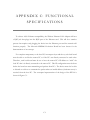
Appendix C: Functional Specifications.................................................................... C-1
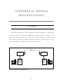
Appendix D: Design Specifications..........................................................................D-1
D.1
Overview..................................................................................................D-1
D.2
High-Level Design..................................................................................D-2
D.2.1 Design Approach ................................................................................. D-2
D.2.2 System Event Diagram ........................................................................ D-3
D.2.3 Transmission of Data from Ethernet to Serial Interface......................... D-6
D.2.4 Transmission of Data from Serial to Ethernet Interface......................... D-8
D.2.5 Block Diagram for the Copy Module .................................................... D-9
D.2.5.1 Flow Chart for the Disassemble Function .................................D-11
D.2.5.2 Flow Chart for the Assemble Function .....................................D-12
D.2.6 System Initiation ................................................................................D-13
D.2.7 Ethernet Interface...............................................................................D-13
D.2.8 Serial Interface ...................................................................................D-13
D.2.9 GetLocalIP Procedure ........................................................................D-13
D.3
Low-Level Design................................................................................ D-15
D.3.1 Global Structures ...............................................................................D-15
D.3.1.1 Description of Buffer Structure..................................................D-16
D.3.1.2 Addition data structure ............................................................D-17
D.3.2 System Initialization ..........................................................................D-19
D.3.3 Module Descriptions...........................................................................D-21
D.3.3.1 Local data Variables ...............................................................D-21
D.3.3.2 Module Pseudocode...................................................................D-21
Appendix E: Verification Plan .................................................................................. E-1
E.1
Performance measurements .................................................................. E-1
vi
E.2
Functionality Tests.................................................................................. E-1
E.2.1 Ethernet module ................................................................................... E-1
E.2.2 Serial module ....................................................................................... E-2
E.2.3 Assemble module.................................................................................. E-2
E.2.4 Disassemble module.............................................................................. E-2
E.2.5 Copy module......................................................................................... E-2
Appendix F: Test plan for the constructed design prototype .............................. F-1
F.1
Preliminary Verification Datasheet ...................................................... F-3
Appendix G: Verification PLan for the Paper Design ..........................................G-1
G.1
Overview..................................................................................................G-1
G.2
Ethernet and Serial Interface Delays ...................................................G-2
G.3
Communications Processor Module (CPM) Utilization ...................G-3
G.4
Software Delays.......................................................................................G-5
G.5
Transceiver...............................................................................................G-5
Appendix H: prototype test/measurement data.....................................................H-1
Appendix I: Design Audit Prototype Demo ………………………………..... I-1
vii
LIST OF FIGURES
Figure 1: Transmission of a Packet from Ethernet to Serial port...............................................18
Figure 2: Transmission of a Packet from Serial to Ethernet Port ..............................................20
Figure 3: Flow Chart for Copy Module ..........................................................................................23
Figure 4: Flow Chart for Disassemble Function ...........................................................................24
Figure 5: Flow Chart for Assemble Function ................................................................................26
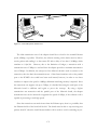
Figure C- 1: Overall System Architecture.....................................................................................C-2
Figure D- 1: Top Level System Diagram..................................................................................... D-1
Figure D- 2: Top Level Structure Diagram................................................................................. D-3
Figure D- 3: System Event Diagram ............................................................................................ D-5
Figure D- 4: Transmission of a Packet from Ethernet to Serial port...................................... D-6
Figure D- 5: Tranmission of a Packet from Serial port to Ethernet ....................................... D-8
Figure D- 6: Block Diagram for Copy Module ........................................................................D-10
Figure D- 7: Flow Chart for Disassemble Function ................................................................D-12
Figure D- 8: Data Flow Diagram for Assemble Function......................................................D-12
Figure D- 9: GetLocalIP Procedure Diagram ..........................................................................D-14
Figure D- 10: Buffer Structure....................................................................................................D-16
viii
LIST OF TABLES
Table 1: Definitions and acronyms in Design Specification Document.....................................iii
Table 2: Design Project Milestones.................................................................................................13
Table 3: Module descriptions ...........................................................................................................16
Table 4: Description of Local Variables used in Copy Module ..................................................28
Table 5: Description of Local Variables used in Assemble Function ........................................29
Table 6: Descriptions of Local Variables used in ser_send Function ........................................32
Table 7: Description of Local Variables used in ser_recv Function ..........................................32
Table 8: Description of Local Variables used in replyARP Function ........................................33
Table 9: Functional Test and Verification Results ........................................................................34
Table B- 1: Summary of Work Distribution ................................................................................B-1
Table B- 2: Design Project Milestones..........................................................................................B-3
Table B- 3: Expected or Known Requirements of the Project.................................................B-5
Table C- 1: Function Specifications of the WELA.....................................................................C-3
Table D- 1: Module Description................................................................................................... D-5
Table D- 2: Description of Global Variables............................................................................D-15
Table D- 3: Description of Constants used during System Initialization .............................D-19
Table D- 4: Description of Local Variables used during Copy Module ...............................D-21
ix
1.0 INTRODUCTION
This document describes the 4th year design project completion status at sign-off time.
In the first section of this document, it describes the milestones achieved and missed at signoff time. It also describes the modifications made to the original design and justification for
the changes. In the second section of the document, it presents a design audit. This design
audit contains the modified design specifications for the software design, which shows the
good software design principles that have been followed. It also contains the test and
verification data for the constructed prototype.
1
2.0 MILESTONES ACHIEVED
AND MISSED
2.1
REASON FOR MISSING MILESTONES
One of the major obstacles encountered is the lack of detailed documentation to the
Motorola board that used for the prototype design. On delivery of the board, there are three
booklets that come with it. All three of them do not contain any documentation as to how
to set up the different ports on the board. After performing some search on the Internet,
we were able to find some sample code for another Motorola board, ADS860. Our board is
MBX860, and the only similarity of the two boards is that both use the same processor,
PPC860, whereas everything else differs between the two boards. Of the sample code that
we downloaded, there is one file that contains the Ethernet port initialization steps. We
have tried to use those steps by executing in the same order with the values set as
appropriate for the MBX860 board. However, this proves to be unsuccessful. After which
we have search on the Internet again, this time, we found the user manual for PPC860, the
processing chip itself. The PPC860 documentation contains a section on Ethernet, and in it
there is a 35-step initialization sequence of the Ethernet port [1]. We have matched the 35
steps with the initialization sequence we got for the ADS860 board and we found some
differences between the two. Upon this discovery, we hope that the cause of our problem
lies in the differences and thus we tried to use the 35-step initialization sequence. However,
after the modifications have been made, we were still unable to perform normal
communication between the PC and the Ethernet port of the Motorola board. With
insufficient documentation, we do not see any clear path to establish communication
2
between the Ethernet port and the PC. This led us to consider the option of loading an
operating system onto the MBX860 board.
We found two alternatives, Embedded Red Hat Linux or Embedded Configurable
Operating System (ECOS). We tried to install both of them, however, the installation for
both OS is unsuccessful. We finally found the sample code of the ECOS driver for the
Ethernet port [2]. There is a different set of initialization sequence from ECOS and when
we modified our code to match that of ECOS, we are finally able to get Ethernet
transmission to work.
We have encountered the same if not higher level of difficulties for setting up the serial
communication. This is due to the fact that neither one of the two operating systems
supports the Serial Port 2 which we need for the transceivers. There is a similar initialisation
sequence in the user manual for PPC860, but like the Ethernet initialisation sequence, we
were unsuccessful at initialisation the serial port. Without a schematic diagram of the
MBX860 board, we have no idea how the different hardware components are related. It is
through testing the ISA before we stumbled upon the method to access the Serial Port 1.
Nevertheless, we are still unable to access the desired Serial Port 2.
We have contacted a Motorola representative about this lack of documentation problem.
The cause is that the MBX860 board we are using is actually a production board, which
Motorola sells to its customers, whom uses this board to develop products and sells to other
companies. As a result, Motorola does not provide any sample code for initializing the ports.
Whereas the ADS860 board is an evaluation board which Motorola uses as well, and thus
the reason there are sample codes for the ADS860 board on Motorola website.
Under limited resources and support, we are still able to meet most of the milestones.
The following section lists the milestones we have achieved and missed at sign-off time.
3
2.2
2.2.1
ETHERNET MODULE
MILESTONES ACHIEVED
For the Ethernet module, the Ethernet controller can be enabled to trigger interrupts
and make the sending and receiving process fully interrupt-driven.
Furthermore, the
prototype is able to receive incoming Ethernet packets and transmit Ethernet packets from
the Motorola board. To ensure 100% Ethernet compatibility with existing network, the
interface of the prototype must be able to update the host’s Address Resolution Protocol
(ARP) table with its IP address. The Ethernet module was able to respond to ARP requests
from the host and reply to PC with the updated hardware address.
2.2.2
MILESTONES MISSED
In the original design, the Ethernet adaptor was designed to update its own IP address
with the IP address of the remote PC’s IP address. This is necessary in order to achieve
truly plug and play installation of the Ethernet adaptor. However, since setting up the
interrupts and the Communication Processor Module (CPM) on the MBX860 turns out to
be much more complicated than imagined, implementing the automatic IP-update feature in
the design cannot be accomplished with insufficient time. For now, the remote PC’s address
is hard-coded in the software code. To change the IP, the software must be re-compile.
2.2.3
2.2.3.1
MODIFICATIONS AND JUSTIFICATIONS
BDS MODIFIED IN ETHERNET MODULE INSTEAD OF COPY MODULE
In the original design, the Ethernet Tx and Rx BDs are assumed to be directly accessible
in the Copy Module’s Assemble and Disassemble routines. With clear understanding of the
CPM, it turns out that there are some special procedures that must be followed before
gaining access to the BDs. Therefore, instead of modifying the BDs directly in the Copy
4
module, the BDs have been made internal of the Ethernet module. The eth_send() and
eth_recv() API functions have been implemented and perform the special procedures inside
these functions. This maintains the software design’s modularity and allows for easier
debugging.
2.2.3.2
GENERATING ARP REPLY
An ARP reply module was not included in the original design for Ethernet module, but
this turns out to be a very important feature in order to support 100% compatibility. If the
prototype does not reply to ARP messages, the host PC will not associate remote PC’s IP
with the Motorola board’s Ethernet hardware address. Therefore, the local PC will not send
outgoing packets with the Motorola board’s hardware address and the Motorola board will
not accept the packets. Therefore, a generate ARP reply function was added to the Ethernet
module in order to achieve Ethernet compatibility.
2.3
2.3.1
COPY MODULE
MILESTONES ACHIEVED
Assemble() was successfully called when serial data is received from the serial module.
In addition, Disassemble() was successfully called when received Ethernet data from the
Ethernet module.
2.3.2
MILESTONES MISSED
The requirements for the Copy module are satisfied at signoff time. However, additional
testing will always yield more reliable and robust code.
5
2.3.3
MODIFICATIONS AND JUSTIFICATIONS
In the original design, the Copy module simply calls Assemble() and Disassemble() in a
round-robin fashion and let the Assemble and Disassemble functions to determine whether
data is available.
In the current design, the Copy module will call the corresponding
interface’s API functions only when the data required by that function is available. This
change is made to make the design more modular. Since the BDs are now kept internal to
the interface modules and calling the corresponding API function will simply return a
pointer to the internal buffer, the Assemble and Disassemble functions now simply copy the
data from one buffer to the other buffer. The Copy module ensures the Assemble() and
Disassemble() will be called only when there are valid data in the buffers, i.e. when the API
functions does not return NULL.
2.3.4
2.3.4.1
DISASSEMBLE BLOCK OF THE COPY MODULE
MILESTONES ACHIEVED
The coding and the testing of the Disassemble block of the Copy module are completed.
The function can successfully take a “controlled” packet from the PC and redirect it to the
Console port (COM 1) of the Motorola Board. However, there are several modifications
made since after the interim report.
2.3.4.2
MODIFICATIONS AND JUSTIFICATIONS
The most significant change is that the serial BD structure no longer exists. The reason
for this is because a different method for the serial interface transmission was used. For
further details of the justifications for the required changes in the serial interface, please refer
to Section 2.4. Thus, instead of performing inspection of the ready data in the serial FIFO,
6
all the code for the validation was moved into the serial interface. The reason for that is to
keep the code as modular as possible, thus, the modification of the serial buffer should be
left to the serial interface. The above decision greatly simplified the Disassemble block. The
Copy module was made responsible to call functions in the Ethernet interface to check for
incoming Ethernet data. In another word, when the Disassemble function is called by the
Copy module, there must be data presents in the Ethernet receive buffer that is ready to be
disassembled. This further simplified the Disassemble block and increased the modularity of
the whole system.
It is decided upon to simplify the Disassemble Block due to the priority to have high
code modularity. The Disassemble Block should only take received Ethernet data and
transfer them into Serial transmit data. The accessing of the control bits, i.e. the empty flag,
for the buffer should be left to the Serial interface. Also, the Copy module should perform
the checking of the incoming Ethernet data and call Disassemble Block accordingly.
Therefore, the validation procedure in the Copy module and the accessing of the control bits
for the buffer are completely transparent to the Disassemble Block itself. This results in
high code modularity.
2.3.5
2.3.5.1
ASSEMBLE BLOCK OF THE COPY MODULE
MILESTONES ACHIEVED
The coding and the testing of the Assemble block of the Copy module are completed.
The function can successfully take a “controlled” packet from the COM 1 of the Motorola
Board and redirect it to the PC. However, there are several modifications made since the
interim report.
2.3.5.2
MODIFICATIONS AND JUSTIFICATIONS
In the original design, the Assemble function is responsible for keeping track of the
7
states in which the Ethernet TxBDs and Serial RxBDs are. The idea behind this original
design is so that the Copy Module is responsible for allocation of resources while the
Ethernet and Serial modules act according to the orders from the Copy Module.
The responsibilities that the Assemble function of the original design has are as follows:
1.
2.
3.
4.
The Assemble function keeps track of the index of the serial RxBD that is
currently being processed.
It checks which Ethernet RxBD is empty.
Responsible for finding free Ethernet Tx buffers by looping through the Ethernet
TxBDs and checking the Ready bit of each one until found one with the status of
Zero.
After data has been loaded into the Ethernet Tx Buffer, set the Ethernet’s Ready
bit to 1.
With the modified design, the above responsibilities are no longer performed by the
Assemble function. Instead, the Copy Module calls functions provided by the Ethernet and
Serial Modules that actually perform the above tasks. In addition, the original design uses
redirection of Ethernet Tx pointers to point to the Serial Rx pointers while the new design
performs actual copying of data from one buffer to another instead of using pointers. The
main goal of these modifications is to keep the three modules as modularized as possible.
With the realization that the CPM must be gracefully stopped when the Status and
Control bits of the BDs are to be changed, the responsible of modifying those bits and
checking those bits to allocate resources must be shifted to the Ethernet and Serial modules
as accordingly. For the Assemble function, this means it must relinquish the responsibility
of checking the availability of the Ethernet Tx Buffers and the presence of Serial packets in
the Serial Buffer. The advantage of shifting these responsibilities to the Copy Module is that
when either Ethernet or Serial resource is not available, the Assemble function will not be
performed. The new structure prevents the unnecessary idle time during looping inside the
Assemble function and can move onto the Disassemble function. When Assemble function
is called, it is ensured that the main task of assembling Serial packets into Ethernet packets is
performed.
8
2.4
2.4.1
SERIAL INTERFACE
MILESTONES ACHIEVED
Successful receive and transmit data through the console port (COM1) of the Motorola
Board was accomplished. When serial data is sent through the COM port of the PC to the
console port of the Motorola Board, the serial interface can receive the data and transfer it to
a designated buffer pool. Also, when data is put in the serial transmit buffer, the serial send
function can transmit the data to the console port of the Motorola Board. All data in the
serial transmit buffer is first converted into ASCII format before transmitting. Therefore,
the display on the screen in the console port is the actual HEX data in the serial transmit
buffer pool.
2.4.2
MODIFICATIONS AND JUSTIFICATIONS
Instead of having a chain of BDs pointing to a large buffer pool, it is decided upon to
use two buffer pools. There is a serial transmit and a serial receive buffer. The size of either
buffer is sufficient to hold an entire Ethernet packet of maximum size, which is 1520 byte.
With single buffer pool implementation, there is no need to provide a BD structure since the
same buffer pool can be reused due to the polling nature of the receive function.
Without the BD structure, there is no need to use the CPM. Therefore, CPM is only
enabled in the Ethernet interface. In the receive function, it will receive the data from the
serial FIFO by polling. The function will exit after it receives the entire EOS from the COM
port of the PC. Since a cable is used as the transmission channel, the error in the channel is
assumed to be zero. That is, the EOS will arrive to the receiver with no error.
As stated in the interim report, the intended method to access the COM2 of the
9
Motorola Board was to use the Serial Management Controller (SMC).
But in this
implementation, the serial output port has been switched to COM 1, which is the console
port of the Motorola Board. Since COM1 of the Motorola Board is used, the maximum
achievable transmission speed is 9600 baud. Accesses to the console port of the Motorola
Board are done by directly controlling the ISA bus where the COM1 is connected.
This
unique method is necessary since the CPM is not initialized and the only way to get access to
communication port is by direct access to the data bus that it is connected.
A single buffer pool is used for either transmit or receive is due to the fact that it is
adequate and sufficient for a polling receive algorithm. For example, when the Copy
Module decided to go into receive mode by waiting for incoming serial data, it blocks until
the entire packet with the EOS. Before the Copy Module perform any further receiving of
serial data, it will call the assemble function to transfer the incoming serial data to a ready to
send Ethernet transmit packet. After that the Copy Module will set the empty flag for the
serial receive buffer. As described, the buffer is used in a strictly sequential fashion and one
such buffer is adequate.
Accordingly, the same reason applies to why only one serial transmit buffer is enough.
The Copy Module copies all the data plus the EOS into the serial transmit buffer and call
serial send function. The function will send all the data out to the console port of the
Motorola Board before returning. After the data has been sent, the serial send function will
set the empty bit of the serial transmit buffer to indicate that it is free for next use.
It was decided upon to use polling algorithm for data access in the serial interface. This
is not the intended method for accessing data. Actually, data-polling algorithm is done
earlier in the project implementation phase and is used for testing in the system integration
phase. However, problems were encountered when tried to change the polling algorithm to
a fully interrupt driven implementation. Documentation and procedures were followed and
appropriate setups have been performed, however, it still failed. It is suspected that the
interrupt from the Ethernet source and the ISA source conflicts each other. One such
explanation might be due to the fact that the normal way of accessing the COM port was
10
omitted. The normal way to access the COM port is through the use of serial channel
provided in by the core processor. Due to the time limit of the project, it is decided upon to
use the polling algorithm that has been proven working. The polling algorithm limits the
performance of the system due to its block receive behaviour. The performance of the
system would be increased if the interrupt driven implementation is used.
In the Motorola Board, there are two COM ports available to use. COM1 is used
because it was discovered that that COM2 does not have a transceiver suitable for a RS-232
interface. Also, a better understanding of the functionality of the COM1 in the Motorola
Board since it is proven working by the debug program for the board can make using COM1
an easier task. However, it is known that when using the console port for data transmission,
connection to the only debug terminal has been lost.
This will make the process of
debugging the code a lot harder later on. Nevertheless, it was still decided to use COM1
because it seems to have a better chance of success using a working COM port instead of
trying to work with a COM port that no documentations are available. Careful measures
were taken to ensure the data is correct before preceded to remove the terminal that
connects to the COM 1 port. For the actual verification and testing, please refer to section
“Testing and Verification for Constructed Prototype” in this report.
Also, for the serial interface, the method to directly access the ISA bus that connects to
the COM 1 port of the Motorola board was chosen instead of the SMC implementation.
The SMC implementation is the safer and cleaner method for accessing the COM port in the
Motorola Board. This is because all the interrupts are grouped together by the Serial
Interface (SI) block before sending it to the core processor. This ensured that the interrupt
are handled properly by priority. However, the initialisation instructions for the SMC stated
in the user manual do not produce successful results, and proper configuration of the SMC
or which registers value to set is unknown. Therefore, it is decided to access the ISA bus
directly to get access to the COM 1 port.
11
2.5
2.5.1
WIRELESS TRANSCEIVERS
MILESTONES ACHIEVED
The wireless transceiver has been ordered and the test program provided along with the
transceiver was used to verify its functionality. It is necessary to verify that the transceiver
can only operate at simplex mode.
2.5.2
MILESTONES MISSED
The development of the wireless transceivers is one of the milestones that have been
missed. Since the wireless transceivers are not considered as the main component of the
project, the amount of time and manpower assigned to them are minimal. Also, when the
transceiver was purchased, it claims that it is very easy to use or simply plug and play.
However, in the testing of the transceivers, configuration procedures are needed in order to
get a minimal error transmission.
By running the test program that comes with the
transceiver, the functionality of a simplex transmission is verified. However, in order to
make it into half or full duplex, more components and development are needed [3]. This
was completely unexpected and time has not been allocated for this purpose. It is strongly
believed that making the transceivers functional will require a vase amount of time since care
must been taken to avoid noise and distortion of signals when inserting additional circuits.
Although getting the transceiver to work is important, many difficulties encountered during
the development phase when working with another more vital part of the design, the
Motorola Board, required the focus of the whole team and thus prevented putting more time
into the transceiver. Thus, at the end, testing of the transceivers cannot be completed.
2.5.3
MODIFICATIONS AND JUSTIFICATIONS
The wireless transceiver needs additional circuitry to make it half-duplex. However, this
modification has not been made yet. The transceiver can transmit data, but the bytes are
12
shifted by half a byte.
connection was used.
This behaviour does not occur when a NULL modem cable
Therefore, additional modifications to the code are required to
compensate for this shift.
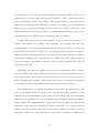
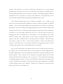
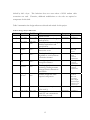
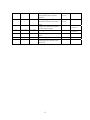
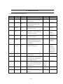
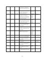
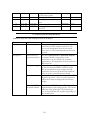
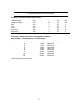
Table 2 summarizes the design milestones achieved and missed for this project.
Table 2: Design Project Milestones
Index
Start Date End Date
Milestones
Initial research
Submit proposal and budget,
find sponsors
Develop initial system design,
finalize requirements and
specifications
Decide on which FPGA and
transceiver to use
Group
Status
All members
All members
Completed
Completed
All members
Completed
All members
End of Jan
2001
Develop handshaking
algorithm to avoid collisions
on wireless channel
All members
Middle of Jan
2001
End of Jan
2001
Investigate possible
encryption schemes
All members
7
Beginning of
Feb 2001
End of Feb
2001
All members
8
Beginning of
Feb 2001
End of Feb
2001
Develop algorithm for
retrieving/sending contents
between wireless transceiver
and FPGA
Finalize design and order
required components
Decided to use
Motorola
board
No longer part
of the
customer
requirement
No longer in
customer
requirement
No longer in
customer
requirement
9
May 01, 2001
May 5, 2001
10
April 20, 2001
May 7, 2001
1
Oct 1, 2000
Oct 30, 2000
2
Nov1, 2000
Nov 31, 2000
3
Dec 1, 2000
End of Dec
2000
4
Beginning of
Jan 2001
End of Jan
2001
5
Middle of Jan
2001
6
All members
Revise customer requirements All members
(due week 2)
Power up Motorola board and All members
verify PC can communicate
with debug console
13
Ordered
Motorola
board and
some sample
National chips,
transceiver not
received yet.
Completed
Completed
11
May 7, 2001
May 14, 2001
12
May 01, 2001
May 11, 2001
13
May 7, 2001
May 11, 2001
14
May 14, 2001
May 18, 2001
15
May 21, 2001
May 31, 2001
16
May 21,2001
June 8, 2001
17
May 21, 2001
May 27, 2001
18
May 21, 2001
May 27, 2001
19
May 28, 2001
June 1, 2001
20
May 24, 2001
June 1, 2001
21
May 28, 2001
June 1, 2001
22
May 28, 2001
June 8, 2001
23
June 1, 2001
June 15, 2001
Verify PC can ping Ethernet
port of Motorola board and
investigate how to control the
Ethernet port
Obtain transceivers from
school lab
Revise project milestones (due
week 3)
Write Functional
specification, Verification
Plan and Test Plan (due week
4)
Investigate, test and verify
wireless communication
between transceivers
Investigate how to retrieve
contents received from
Ethernet port on Motorola
board and write algorithm to
retrieve the content.
Develop PC application to
send/receive packets between
PC and Ethernet controller;
Verify packet contents
Write Design Specification
and project interim report
(due week 5)
Investigate how to access
COM2 of the Motorola board
in order to read/write to the
transceiver
Request for the 2nd Motorola
MBX Evaluation Board
Order and receive a new
transceiver from RF Digital
Implement and test algorithm
for reading and sending to
transceiver
Test transceiver for
functionality
14
Embedded
PowerPC
Software –
Ethernet
module
Wireless
Transceiver
Completed
All members
Completed
All members
Completed
Wireless
Transceiver
50%
Completed
Embedded
PowerPC
Software –
Ethernet
module
Completed
Embedded
PowerPC
Software –
Ethernet
module
All members
Completed
Embedded
PowerPC
Software –
serial port
module
Embedded
PowerPC
Software –
Ethernet
module
Wireless
Decided to use
COM 1.
Completed.
Decided to
order our own
Completed
Completed
Completed
PC utility
software
To do
Wireless
50%
Completed
24
June 5, 2001
June 15, 2001
25
June 10, 2001
June 20, 2001
26
June 10, 2001
June 17, 2001
27
June 17, 2001
July 7, 2001
28
July 1, 2001
July 7, 2001
29
July 16, 2001
July 20, 2001
30
July 16, 2001
July 22, 2001
Write programs in PC to
disassemble and assemble
packets
Write programs in PC to send
and receive data in the serial
port
Merge the different modules
of the code together
Testing of the entire system
Target project completion
date
Project signoff (due week 12)
Design project abstract (due
week 13)
15
PC utility
software
Completed
PC utility
software
Completed
All members
70%
Completed
All members
70%
Completed
To do
All members
All members
To do
To do
3 . 0 D E S I G N AU D I T
3.1
HIGH LEVEL DESIGN
The overall high-level design remains the same as the original design in the interim
report with some minor modifications made to it. Please refer to Appendix D for the
original design specification. In the new design, the Ethernet module, copy module, and
serial module still act as the three main components of the design. To keep the modules
more self-contained, thus making them have higher cohesion and lower coupling, the
number of the buffers have been limited and various flags internal to the modules only are
used and other modules can only access those buffers through API function calls. For
example, the Tx and Rx BDs cannot be directly accessed by the Copy module; instead, the
Copy module must call functions to obtain access to the Tx buffer or to set the BD empty
bits.
Table 3 provides the modified module descriptions for the prototype design.
Table 3: Module descriptions
Module
Description
Serial_Interface
The Serial Block is used to transmit or receive data from the serial
port. It consists of receive and sending API function which other
modules can call. It also contains an internal Tx and Rx buffer pool
which is used to hold data to be transmitted or received from serial
port. To use these buffers, certain flags must be set, and API
functions are provided to modify the flags.
16
Ethernet_Interface
The Ethernet ISR Block is used to transmit or receive data from the
Ethernet interface. It contains buffers to hold data and it contains
an interrupt ISR to service interrupts generated by events related to
the Ethernet port. This module is also responsible for modifying
Ethernet BDs. When new data is received from the Ethernet port,
an interrupt will be generated after new data is copied to a buffer.
External modules can access the data by calling API send or receive
functions.
Copy_Block
The Copy Block is used to coordinate the data manipulation between
the Ethernet port and the serial port. It will call the interface’s
receive functions alternately. If data from the Ethernet interface is
ready, it will disassemble the packet into smaller serial port packet.
For data coming in from the serial port stored in serial buffer, it will
reassemble the packet into larger Ethernet port packet.
Initialization
The Initialization block is used to set up and initialize all global data
structures. This part remains the same as the design specification in
interim report.
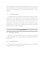
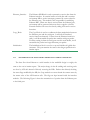
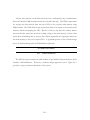
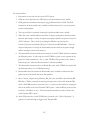
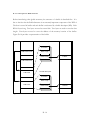
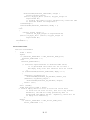
3.1.1
TRANSMISSION OF DATA FROM ETHERNET TO SERIAL INTERFACE
The data flow from Ethernet to serial interface in the modified design is roughly the
same as the one in interim report. The major change is that all sending and receiving tasks
are done by API calls instead of directly accessing the BDs. Rather than directly checking
the status flags modified by the ISR, the Copy module now must obtain the current status by
the return value of the API function calls. The flags are kept internal inside the interface
modules. The following Figure 1 shows the transmission of a packet from the Ethernet port
to the Serial port.
17
System Ethernet_Serial_System
(from Ethernet to Serial)
Initialization
Initialize
Initialize
Initialize
Status
(7)
Update
(13) Decrement
(8)Check
Ethernet Interface
Copy Block
(10) Pointer
Ethernet ISR
Assemble
(1)
Get Serial Buffer
(2)Return Ptr
Serial Interface
Serial ISR
(7) ISR
CPM
(3) & (9) Receive
(14) Tx_Data
(3) Receive
Ethernet
Cleanup
(11) Call
Rx_Data
(5) Rx
FIFO
(4) Waiting
FIFO
Tx Buffer Flag
Disassemble
(17) Empty
(15) set empty
(16) Done
(18) Call
(6) Copy
Data
Ethernet Packet
Buffer
(2)Check
Buffer
(12) Copy
Serial Data Buffer
Figure 1: Transmission of a Packet from Ethernet to Serial port
The following sequence is used to process the data packet until it is transmitted out of
the serial interface in the modified design:
1. Copy module gets a serial Tx buffer from serial module by calling ser_getTxBuffer.
2. In ser_getTxBuffer(), if the serial Tx buffer is not in use, it returns a pointer to Tx
buffer and sets a flag to indicate the Tx buffer is now in use.
3. Copy module calls eth_recv(). If no packets are ready, then it quits and call
ser_recv().
4. In the normal flow, the program will always be inside ser_recv(), waiting for a
complete packet from serial interface until EOS is detected.
5. Data packet is received into the Ethernet receive FIFO queue.
6. CPM moves the data from the FIFO queue into the Ethernet receive buffer.
18
7. CPM generates an Ethernet interrupt to trigger Ethernet Receive ISR. The ISR
increments the disassemble status variable to indicate that there is one more packet
ready for disassemble.
8. The ser_recv() is constantly checking for the disassemble status variable. If
disassemble variable is greater than zero, it immediately returns to copy module.
9. Copy module calls eth_recv() again.
10. eth_recv() detects the BD is not empty, so it returns a pointer to the contents of the
Rx buffer and increment it’s RxBD index to point to the next BD, which is the
buffer that CPM will use when the next packet arrives.
11. Copy module received the pointer to the Ethernet Rx buffer containing the new
packet. It calls the disassemble function.
12. The disassemble function copies the binary data to the serial Tx buffer, append “end
of sequence” pattern and calls ser_send().
13. ser_send() converts binary data to ASCII data, decrements disassemble status
variable to indicate the data packet stored in the buffer has been disassembled.
14. ser_send() sends data to serial port until the whole packet
15. ser_send() sets Tx buffer flag to be empty so that the Tx buffer can be re-used by
next call. Ser_send() returns.
16. disassemble() calls eth_setRxBufferEmpty() to indicate it has finish using the current
BD buffer.
17. eth_setRxBufferEmpty() sets the empty bit of the RxBD
18. disassemble() calls ser_getTxBuffer() again to get a pointer to the serial buffer to
prepare for next transmission.
19
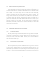
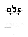
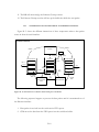
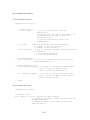
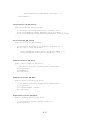
3.1.2
TRANSMISSION OF DATA FROM SERIAL TO ETHERNET INTERFACE
Figure 2 shows the different interactions of these components when a data packet comes
in from the serial interface.
System Serial_Ethernet_System
(from Serial to Ethernet)
Initialization
Initialize
Initialize
Initialize
Ethernet Interface
Serial Interface
Copy Block
(6) Return Ptr
Ethernet ISR
Assemble
Serial ISR
CPM
(5) & (14) Get Tx Buffer
Ethernet
Cleanup
(2) & (3)
Get Ready Serial Buffer
FIFO
(11) Call
Tx_Data
FIFO
(12) Tx
(1) Rx_Data
(4)Return Ptr
Disassemble
(13) Done
(10) Ready
(8) Call Send
(9) Link to
Packet
(11) Copy
Data
(3)Copy
(7) Copy
Ethernet Packet
Buffer
Serial Data Buffer
Figure 2: Transmission of a Packet from Serial to Ethernet Port
The following sequence happens to process the data packet until it is transmitted out of
the Ethernet interface:
1. Data packet is received into the serial receive FIFO queue.
2. Copy module will usually be inside ser_recv().
3. ser_recv() polls the status bit in serial interface and copies to serial Rx buffer until
20
EOS is detected. At this point ser_recv() returns to Copy module.
4. Copy module receives a non-NULL pointer to serial Rx buffer. Therefore it will
convert ASCII characters back to binary and calls Assemble function
5. Assemble function calls eth_getTxBuffer() to get a pointer to the next available
Ethernet Tx buffer
6. eth_getTxBuffer() returns the next free Tx buffer and increments its own Tx buffer
index. This is the buffer which CPM will be checking for ready bit.
7. Assemble function copies data from serial Rx buffer to Ethernet Tx buffer
8. The Assemble function calls eth_send() to send data.
9. The Assemble function will link the data in the serial RX BD into a packet.
10. eth_send() sets the ready bit of the Ethernet Tx BD to indicate to the CPM that the
packet is ready for transmission.
11. The CPM will move the ready Ethernet TX BD’s packet to the FIFO queue for
transmission. The ready bit of the Ethernet TX BD will be automatically cleared by
the CPM after the packet is moved to the FIFO queue.
12. The packet will get transmitted through the Ethernet interface.
13. eth_send() returns to Assemble() function. Assemble function now calls
set_serRxBufferEmpty() to indicate to serial module that it has finished using the
current Rx buffer.
14. eth_send calls eth_getTxBuffer() to get a new Ethernet Tx buffer to prepare for next
transmission.
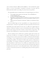
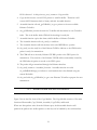
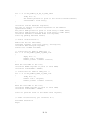
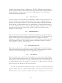
3.1.3
BLOCK DIAGRAM FOR THE COPY MODULE
Figure 3 shows the flow chart of the Copy Module. The Copy Module consists of five main
functions: Disassemble, CopyToSerial, Assemble, CopyToEth, and Search.
When new data packets arrive from the Ethernet port, the disassemble function will
partition the packets into smaller packets so that they can be handled by the serial interface.
21
After all the smaller partitions of an Ethernet packet are sent, it will call
eth_setRxBufferEmpty() to set the empty bit of the Ethernet receive buffer. When new data
arrive from the serial port, the assemble function will reassemble all the partitioned packets
that the serial port has received back into an Ethernet packet. The Search function searches
for the EOS pattern to indicate the end of an Ethernet packet. One serial receive may
contain more than one Ethernet packet fragments. The Search function is used to
distinguish between the last fragment of the current Ethernet packet and the first fragment
of the next Ethernet packet. After the Ethernet packet is sent to PC, the Copy module will
call ser_setRxBufferEmpty() to indicate to serial module that the current Rx buffer can be
re-used for next reception of serial data.
22
Start
No
Free Space in
Ethernet TxBD?
Yes
"Ethernet packet
waiting for
disassemble?"
Yes
No
No
"Is it ARP
packet?"
Yes
Check for Free Serial Tx
Buffers
"Free Serial Tx
Buffer?"
remove this packet from Ethernet
Rx Buffer by calling
eth_setRxBufferEmpty()
Yes
No
Disassemble()
Serial Rx
packet
waiting?"
Yes
twoByteToHex(tempbuf,
Eth_Rx_Length)
No
"Ethernet Tx Buffer
Available?"
Yes
Assemble()
remove this packet from
Serial Rx Buffer by calling
ser_setRxBufferEmpty()
Figure 3: Flow Chart for Copy Module
23
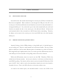
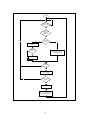
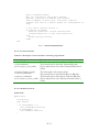
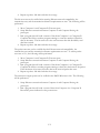
3.1.3.1
FLOW CHART FOR THE DISASSEMBLE FUNCTION
Figure 4 is the flow chart of the working Disassemble block of the Copy module.
Disassemble
Start
CopyToSer(Serial_Tx_
Ptr, Eth_Rx_Ptr,
Eth_Rx_Len)
ser_send(Eth_Rx_Len+4)
eth_setRxBufferEmpty()
End
Figure 4: Flow Chart for Disassemble Function
As shown in Figure 4, the new Disassemble block simply copy the data from the
Ethernet receive buffer to the serial transmit buffer. Then it will pad four byte of “End Of
Sequence” (EOS) to indicate to the serial receive (at the other end) that the end of the
Ethernet packet is reached. Therefore, the length passed into the function “ser_send” is
increased by four to let the send function not only send the entire Ethernet packet, but also
include the EOS bytes. After it finished sending the data, the Disassemble function will call
“eth_setRxBufferEmpty” to set the Empty bit of the Ethernet Receive BD.Flow Chart for
the Assemble Function.
24
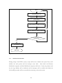
3.1.3.2
FLOW CHART FOR THE ASSEMBLE FUNCTION
As shown in the following Figure 5, the Assemble function has been greatly simplified.
The Assemble function no longer checks which Serial Rx Buffer contains data and which
Ethernet Tx Buffer is empty. In addition, it does not have to wait for notification from the
Ethernet Module that the Ethernet packet has actually been sent to the PC and that it is now
empty and can be reused.
The functionalities which the new Assemble function is
responsible for are: to search for the “End of Sequence” in the Serial buffer, remove it and
copy it over to the Ethernet buffer; if an Ethernet packet spans across more than one Serial
buffer, then the Assemble function ensures the correct data and length of the Ethernet
packet. After the whole packet has been copied to the Ethernet side, it will call the function,
“ser_setRxBufferEmpty()” to notify the Serial Module that the Serial Buffer has been
processed.
25
Start
Set Start, End = 0;
Search for "end of packet"
sequence, record the end position
of the packet
Add Previous_Length to Length
No
Copy data from Serial to Ethernet
Found "end of packet"
sequence?
Yes
eth_send(Length);
eth_setEthBuffEmpty()
;
State Idle
Figure 5: Flow Chart for Assemble Function
3.1.4
SYSTEM INITIATION
During startup of the WELA system, a script will be run to initialize the system. First, it will
initialize the stack pointer and the interrupt vector table.
After which the Ethernet
Initialization sequence and Serial Initialization sequence will be ran. Lastly, the pointers used
by the Copy Module will be initialized, the Rx interrupts will be enabled, and finally the
GetLocalIP procedure will be executed before returning to the main routine.
26
3.1.5
ETHERNET INTERFACE
The Ethernet Interface module contains of four API functions and one interrupt routine.
Eth_send() sends the data in the current Ethernet Tx buffer. Eth_recv() polls the empty bit
of the current RxBD and returns the current Rx buffer if a new packet has arrived.
Eth_setRxBufferEmpty() sets the current Rx BD’s empty flag. Eth_getTxBuffer() gets the
current Tx buffer if it is ready for use. The interrupt routine will be executed after a packet
has been received from the computer into the Ethernet Interface. During the execution of
this interrupt, the Copy Module will be notified that a new packet has been received and
increment a counter that keep tracks of total number of packets stored in the Receive Buffer.
3.1.6
SERIAL INTERFACE
The serial Interface module contains four API functions. Ser_send() sends the data in the
current serial Tx buffer. Ser_recv() polls the data ready bit of the current serial status
register, and copy the current byte to receive buffer in main memory. It keeps copying new
serial bytes to receive buffer until the EOS is detected. Eth_setRxBufferEmpty() sets the
current Rx BD’s empty flag. Eth_getTxBuffer() gets the current Tx buffer if it is ready for
use. The interrupt routine will be executed after a packet has been received from the
computer into the Ethernet Interface. During this interrupt routine, the Copy Module will
be notified about the data length of this new set of serial data for the reconstruction of
different sets of serial data into one complete packet.
3.1.7
GETLOCALIP PROCEDURE
This feature is not implemented yet at this point in time.
27
3.2
LOW LEVEL DESIGN
Table 4: Description of Local Variables used in Copy Module
Variable Name
int RxPtrFound
int FoundARP
Char *Eth_Tx_Ptr`
char *Eth_Rx_Ptr
int Eth_Rx_Len
Char *Serial_Tx_Ptr
Char *Serial_Rx_Ptr
Int End_Of_Sequence_Found
Int Previous_Length
3.2.1
Description
Indicate if a free Ethernet Buffer is found..
Indicate if the entry in Ethernet Buffer is ARP.
Pointer to the current Ethernet Tx Buffer.
Pointer to the current Ethernet Rx Buffer.
Length of the currently pointed to Ethernet Rx Buffer
Pointer to the current Serial Tx Buffer.
Pointer to the current Serial Rx Buffer.
End of sequence found for the current packet
Length of Ethernet Packet split into two Serial Buffers.
COPY MODULE
Module Main
{
eth_int();
loop until ( (Eth_Tx_Ptr = eth_getTxBuf()) != NULL )
loop forever
{
if (!RxPtrFound)
{
/*
Check to see if there is an Ethernet Packet waiting for
disassemble*/
if ((Eth_Rx_Ptr = eth_recv(&Eth_Rx_Len)) != NULL)
{
RxPtrFound = TRUE;
/* Search the current Ethernet Rx packet to see if it is an
ARP message or not*/
ARP_Init(&FoundARP, Eth_Rx_Ptr);
if (FoundARP != TRUE)
{
/* Check for a Free Serial Tx Buffer so that the
Ethernet Packet can be copied over*/
Serial_Tx_Ptr = ser_getTxBuf();
if (Serial_Tx_Ptr != NULL)
{
call Disassemble function;
RxPtrFound = FALSE;
}
}
else
{
28
/* It is an ARP message, which has been replied
when ARP_Init() function was called*/
call eth_setRxBufferEmpty();
FoundARP = FALSE;
RxPtrFound = FALSE;
}
}
}
/* Check to see if a Serial Packet is waiting for assemble*/
if ((Serial_Rx_Ptr = ser_recv(&Serial_Rx_Length)) != NULL)
{
/*Function twoByteToHex is used to convert ASCII into
HEX*/
call twoByteToHex(tempbuff, Serial_Rx_Ptr) function;
Serial_Rx_Ptr = tempbuff;
if (Eth_Tx_Ptr != NULL)
{
call Assemble() function;
ser_setRxBufferEmpty();
SerRxPtrFound = FALSE;
}
}
}
return 0;
}
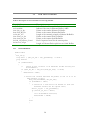
3.2.1.1
DISASSEMBLE BLOCK
Function Disassemble()
{
CopyToSer(Serial_Tx_Ptr, Eth_Rx_Ptr, Eth_Rx_Len);
//+4 for the four end of sequence bytes
ser_send(Eth_Rx_Len+4);
eth_setRxBufferEmpty();
}//End Disassemble
3.2.1.2
ASSEMBLE BLOCK
Table 5: Description of Local Variables used in Assemble Function
Variable Name
int End
int Start
int Length
Description
Indicate end position of the packet
Indicate start position of the packet
Indicate length of the packet
Function Assemble
29
{
loop until ( (Previous_Length == 0 || Start == 0) && (Start <
(Serial_Rx_Length -1)) )
{
Search(Start, End, End_Of_Sequence_Found, Serial_Rx_Length );
Length = End - Start + 1;
CopyToEth(Eth_Tx_Ptr+Previous_Length, Serial_Rx_Ptr + Start,
Length);
/*This condition is for the Ethernet Packet fits inside the
Serial Buffer*/
if (End_Of_Sequence_Found)
{
/* Notify Ethernet side that this packet is ready*/
eth_send(Length + Previous_Length);
Previous_Length = 0;
End_Of_Sequence_Found = 0;
Start = End + 5;
//End of sequence takes up 4 bytes
}
/* The Ethernet packet spans more than 1 Serial Buffer*/
else if (!End_Of_Sequence_Found)
{
Previous_Length += Serial_Rx_Length - Start;
ser_setRxBufferEmpty();
}
/* For cases when the Ethernet packet length is the same as the
Serial Buffer size*/
if (Start > (Serial_Rx_Length-1) )
{
ser_setRxBufferEmpty();
}
}
}
3.2.2
3.2.2.1
ETHERNET FUNCTIONS
ARP_INIT
void ARP_init
{
if received packet is ARP request packet
{
loop until get an Ethernet Tx Buffer
Fill the Buffer with the ARP header and destination address
call eth_send() to send out the packet
set the Ethernet Rx Buffer to empty
}
}
30
3.2.2.2
ETH_INIT
void eth_init
{
initialize BD
setup interrupt
initialize SCC1
}
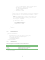
3.2.3
3.2.3.1
SERIAL FUNCTIONS
SER_SETRXBUFFEREMPTY FUNCTION
Function ser_setRxBufferEmpty
{
/* This function just set the flag (ser_RxBufferPoolEmpty) to TRUE,
if the flag (ser_RxBufferPoolEmpty) is FALSE*/
if (!ser_RxBufferPoolEmpty)
ser_RxBufferPoolEmpty = TRUE;
}
3.2.3.2
SER_GETTXBUF FUNCTION
Function ser_getTxBuf
{
/* If the flag (ser_TxBufferPoolEmpty) is not empty,
it means that the previous data has not been send yet.
The user should call ser_send(int len) to send out the data
At the end of that send function, the flag will be set to TRUE.*/
if (!ser_TxBufferPoolEmpty)
return NULL;
/* If the flag (ser_TxBufferPoolEmpty) is empty,
then return the address of the serial Tx Buffer Pool.
It also set the flag (ser_TxBufferPoolEmpty) to FALSE,
indicate that there will be data in the buffer that is not send.*/
ser_TxBufferPoolEmpty = FALSE;
return ser_TxBufferPool;
}
31
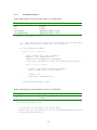
3.2.3.3
SER_SEND FUNCTION
Table 6: Descriptions of Local Variables used in ser_send Function
Variable Name
int I
int j
char tempChar
char tempByteStr[3]
Description
Counter
Counter
Temporary storage of a char
Temporary storage of a byte
Function ser_send(int len)
{
/*
This function will ONLY run if the Buffer Pool is NOT empty,
which means that there is some data in the buffer.*/
if (!ser_TxBufferPoolEmpty)
{
for (i = 0; i < len; i++)
{
while (!(COM1->LSR & LSR_TX_EMPTY));
tempChar = ser_TxBufferPool[i];
oneByteToAscii(tempByteStr, &tempChar);
// One Byte converted to 2 byte for sending ascii display.
for (j = 0; j < 2; j++)
{
//spin if Tx holding register not empty
while (!(COM1->LSR & LSR_TX_EMPTY));
//send it out
COM1->buf = tempByteStr[j];
}
}
ser_TxBufferPoolEmpty = TRUE;
}
}
Table 7: Description of Local Variables used in ser_recv Function
Variable Name
int pktFlag
int I
Description
Indicate if a packet has been found
Counter
Function ser_recv(int *len)
{
// If the pool is not empty, then return NULL)
// Means that the user forgot to call setSer_RxBufferEmpty() function
if (!ser_RxBufferPoolEmpty)
32
return NULL;
// The serial receive buffer pool is empty.
// This function will also receive the length of packet received thru
(len).
while (i < BUFFER_SIZE && pktFlag == FALSE)
{
while (!(COM1->LSR & LSR_DATA_READY));
ser_RxBufferPool[i] = COM1->buf;
i++;
}
*len = i;
ser_RxBufferPoolEmpty = FALSE;
return ser_RxBufferPool;
}
3.2.4
ARP REPLY FUNCTION
Table 8: Description of Local Variables used in replyARP Function
Variable Name
ARPPkt requestPkt
ARPPkt replyPkt
Description
The ARP request packet received
The ARP reply packet generated
Function replyARP(const ARPPkt_t* requestPkt, ARPPkt_t* replyPkt)
{
copy the local HW address to source field
copy the original sender's HW address into the dest field
set message type to ARP_REPLY
copy source HW address into source field inside ARP header
copy target HW address into dest field inside ARP header
copy target IP address into ARP header
}
33
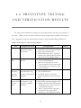
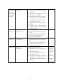
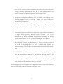
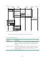
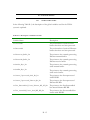
4.0 PROTOTYPE TESTING
A N D V E R I F I C AT I O N R E S U LT S
The testing results indicate the design can successfully transfer data from one interface to
the other. Table 9 shows the basic essential customer requirements satisfied at this stage in
time. Appendix I shows the demonstration results to faculty member Roger Sanderson.
Table 9: Functional Test and Verification Results
Test
ARP test
Components tested
Test procedure
ARP reply feature,
1. Verify PC’s ARP table does not
Ethernet transmit
contain the entry for the local board.
and receive
2. Ping local board from PC.
3. Check ARP table of PC. It should
contain entry which maps IP address
with the board’s hardware address.
Serial unit
Serial transmit and
1. Write a test program which echo
Test
receive
received serial character.
2. Run the test program on board.
Type characters to the console port.
You should see the characters echo
onto the screen.
Send
Ethernet receive,
1. Run our program on board.
Ethernet
serial transmit, copy
2. Ping board from PC.
packets
module’s disassemble 3. An ASCII version of the ping
from PC
function.
packets should show up on console
port.
Send ASCII Ethernet transmit,
1. Run program on board.
packet from serial receive, copy
2. Run packet monitor program on PC.
console
module’s assemble
3. Send pre-defined valid ASCII packet
port
function
which represents textual version of
a valid Ethernet packet
4. The PC’s packet monitor program
should show the same packet
appearing at the Ethernet interface.
34
Result
Pass
Pass
Pass
Pass
NULL
modem
connects
two board’s
serial port
together
All except
transceivers
Ethernet
Stress test
Ethernet receive,
serial transmit
Ethernet
Stress test
Ethernet receive,
serial transmit
Stress test
All except
transceivers
1. Connect one board’s Ethernet port
to PC A, one board Ethernet port
to PC B.
2. Download our program to the two
boards via console port.
3. Run program on the two boards,
unplug from PC and connect the
two board’s serial port together
using NULL modem.
4. Run network monitor program on
PC B.
5. Ping from PC A. Packet monitor
program on PC B should show PC
A’s ping packet.
1. Run program on board.
2. Run network monitor program on
PC.
3. Ping board from PC continuously.
4. Packet data should display on
console continuously.
1. Run program on board.
2. Run network monitor program on
PC.
3. Ping board from PC continuously.
4. Packet data should display on
console continuously.
1. Run program on board.
2. Run network monitor program on
PC.
3. Ping board from PC.
4. At the same time, send ASCII
packets to board.
5. Ping packet’s content should show
on console, while ASCII packets
should show on network monitor
program.
35
Pass
Pass
Pass
Fail. On
examining
the BD’s
content; it
was
shown
that there
are
numerous
collisions
occurring.
Transceiver
unit test
Transceiver
communication
1. Connect transceiver A to PC A’s
console and connect transceiver B to PC
B’s console.
2. Type characters on PC A. The same
characters should appear on PC B.
System
integrated
test.
All
1. Same setup as NULL modem test
except use transceivers to connect to
serial port instead of NULL modem
cable.
2. PC A’s ping packet content should
show on PC B.
Fail.
Some
packet
content
received
on PC B
are shifted
by half a
byte but
some
packets
are okay.
Fail.
Since the
transceiver
fails its
unit test.
As shown in the above Table 9, the basic functionality of the design is met. However, at
the present time, total optimisation for the prototype has not been completed and thus, with
the interest of the customers in mind, it is not wise to move onto full-scale manufacturing
level deployment as of now. Nevertheless, if given more time to fully optimise and to
perform extensive testing on the design, it can prove to be a successful product. The
following lists the areas that should be improved before full-scale deployment.
1. The performance of the design can be increased significantly if the serial
interface can be implemented to be fully interrupt-driven. The polling approach
is inherently slow and there is a possibility that if the program does not poll fast
enough, some serial bytes might be lost.
2. The current implementation makes use of COM1, the console port, instead of
COM2. This is not the ideal port to use since access to any debugging messages
is lost if a runtime error occurs. If any debug messages occur, the debug
message’s text will be treated as data embedded in the received serial data. This
36
will upset the operation of the program since the buffers will contain the debug
message embedded with the actual data. In the final implementation of the
project, COM2 should be used to transmit data instead of COM1.
3. The current implementation fails the stress test where many collisions occur.
Therefore, the design must be improved to better handle error conditions in
transmission and receptions.
4. The data are shifted by 4 bits when sending using transceiver. This may be due
to the problem that there is 1 byte preamble before transmission. More time is
needed to resolve this issue.
5. The transceiver pair received from the vendor only support simplex transmission.
To support duplex operations, additional circuitry is required. This was not
mentioned in the transceiver website when purchased was made and thus the
required additional time was not allocated for building the extra circuitry.
6. The GetLocalIP feature is not implemented yet. This is necessary in order for
the module to dynamically change its own IP address when plugging into
different machines. The IP address is currently hard-coded and fixed at compiletime.
7. 100% TCP/IP compatibility is not achieved yet since Netscape will stop working
when the network cable is removed and the prototype has been attached. The
packet can arrives the destination successfully, but there are not responses from
the other computer. It is suspected that there are some address fields in an IP
packet require modification that is causing this problem.
It is strongly believed that given more time, the problem areas as stated above would be
fixed before the final product demonstration in January 2002.
37
4.1
PLAN FOR IMPROVING THE NOT-YET PERFECT AREAS
A high priority should be given to make the serial transmission and reception fully
interrupt-driven. More time is needed to investigate how to make CPM accept interrupts
from the ISA bus controller. The priority assignments of the CPM interrupts must also be
investigated so that both Ethernet and serial interrupts can be handled correctly.
The current design fails the stress test where collisions occur. This must be resolved
before going for full-scale production. From the current knowledge of the CPM, it is known
that when CPM senses an error when receiving, it will skip the current BD and proceed to
next BD. Therefore, the current RxBD will contain the partially received packet and will
never be emptied again. Therefore, the Ethernet ISR must be notified such that it will reset
the empty bit when an error occurs.
It is also necessary to have the timer enabled in order to calculate the processing delay of
the software code. The timer must be running on the board in order to obtain accurate
measurement of the speed. More time is needed to enable the system timer on the Motorola
so that it trigger an interrupt every certain second. A counter will be incremented each time
the ISR is triggered. By reading the counter value change, the delay can be calculated from
receiving a packet to sending to the other interface.
Finally, the GetLocalIP procedure needs to be implemented so that it automatically
updates the local board’s IP address. This can be done by pinging the local PC and retrieve
the IP address of the local PC from the reply message. More research on IP protocol is
needed.
38
5.0 REFERENCES
[1]
Motorola Inc., “MPC8260 PowerQUICC II User’s Manual”. Motorola Inc., 1999.
[2]
Red Hat Inc., “ECOS CVS,” http://sources.redhat.com/ecos/ (current July 09,
1999)
[3]
Linx Technologies, “HP Series-II Receiver Module Design Guide”, Linx
Technologies, 2000.
39
APPENDIX A: CUSTOMER
REQUIREMENTS
The design of the WELA is fully based on the Customer Requirements. It is agreed with
the customer of the WELA that it is to be 100% compatible with the existing Ethernet
technology (IEEE 802.3).
This is the first priority according to the customer.
This
requirement is especially important as it allows users to turn an existing configured, wired
Ethernet network to a wireless Ethernet network without any additional capital spending
expect for this device. To verify that the device is 100% compatible with Ethernet standard,
the prototype will be attached to the Ethernet port and check for network functionality.
The second priority from the customer is cost. The customer only provides $400 for the
construction of this prototype. Therefore, the components of the prototype of the WELA
are mostly sponsored from other companies. However, the cost of the final product can be
reduced significantly in mass production.
Another critical requirement from the customer is the transmission rate, which is the
third priority. The ideal transmission rate should be as close to normal Ethernet speed,
10Mbps, as possible. However, due to the limited budget, a slower prototype is build to
demonstrate the concept of the device. To conserve budget, it is agreed that a transceiver
with a maximum transmission rate of 50kbps is used for this prototype. In addition, the
maximum transfer rate of the serial port on the Motorola board used is 2.4Mbps. The
logical processing of the code used also requires additional time. Upon completion of the
prototype, if there is an interest in the device from the customer, the transmission rate can
easily be improved by using faster transceiver, faster processor, and optimisation of codes.
A-1
The fourth, fifth, and sixth priorities from the customer are the transmission distance,
the packet error rate and the transceiver output power respectively. The customer requires
that the device can support a maximum distance of 25 meters under normal condition with a
packet error rate of less than 2%. The customer stated that normal condition is one in
which there are no obstacles between the two devices. As discussed with the customer, the
transmission distance and the packet error rate can be improved by selecting faster
transceiver that will have a stronger signal. For the transceiver output power, the customer
requires the RF output power of the transceiver to be less than 1mW. A longer transmission
distance can be achieved if the maximum output power requirement is relaxed. A 1W
output power is limited due to regulations from Industry Canada.
The last priority is scalability. The customer requires that the WELA can support a Class
C Ethernet network. Due to limitation of budget, it is agreed that a point-to-point prototype
is built for proof of concept. To accommodate more network nodes, we advised the
customer that a separate collision algorithm has to be implemented.
Table A-1: Summary of Customer Requirements
Priority
1
2
3
4
5
6
7
Requirement
Compatibility with
existing Ethernet network
Cost
Speed (baud rate)
Distance
Packet Error Rate
Maximum transceiver
output power
Scalability
Measurable
100% compatible (no reconfiguration at terminals
required)
Mostly sponsored
50kbps
25m
2%
1mW
Point to point
A-2
APPENDIX B: PROJECT PLAN
AND MILESTONES
B.1 PROJECT PLAN
Work distribution:
This project will be subdivided into several functional groups. Each group member will
be responsible for working on his own area.
Table B- 1: Summary of Work Distribution
Group Name
Wireless
transceiver group
Description of Responsibilities
Expected Design Challenges
This group will be responsible for ensuring
♦ Interface the transceiver
the pair of transceivers can communicate to
with the RS-232 port.
each other and meets all RF requirements.
♦ Making sure that the voltage
Tasks include choosing a proper antenna
logic level is the same for
and suitable ground plate, testing the wireless
the Motorola Board and the
communication between the transceivers, and
transceiver.
measuring the output power.
♦ Ensure transceivers can
operate in full-duplex mode;
Ricky and E’Kong will be responsible for
if not, handshaking
this component of the project.
algorithms needed for halfduplex operations.
B-1
PC utility
software group
This group will be responsible for writing all
the test programs on the PC side in order to
test sending and receiving packets to the
Ethernet port. These programs can be used
not only to test the functionality of the
prototype, but also for obtaining different
statistics about the performance of our
prototype. It can also provide useful
information when debugging our embedded
code running on the Motorola board. The
group also needs to write programs to send
pre-build packets to the serial port and to
receive and display packet received from the
serial port.
♦ Mastering Windows socket
functions.
♦ Develop algorithm to
calculating the speed of
transmission accurately.
♦ Develop software to
assemble and disassemble
packets for display and
transmission.
Tim and E’Kong will be responsible for
writing these Win32 based software.
Embedded
PowerPC
software group–
Ethernet module
This group will be responsible for getting
familiar with the use of the Ethernet port on
the Motorola board. Writing software code
to access packets with the Ethernet port and
a buffer residing on the Motorola board.
Main tasks include ensuring the PC and the
board can communicate to each other, and
write code to read and write packets from the
Ethernet port.
♦ Minimizing the delay
between receiving a packet
and sending to the other
interface.
♦ Partitioning packets into
smaller size for serial
transmission.
Tim and Henry will be responsible for
writing the code for this component.
Embedded
PowerPC
software
group – Serial
port module
This group will be responsible for getting
familiar with the use of the serial port on the
Motorola board and write software code to
access the serial port. The serial port is the
port to be connected to the data pins of the
transceiver. Main task including writing
code to read and write to the transceiver.
Ricky and Henry will be responsible for
this part of the project.
B-2
♦ Minimizing the delay
between reader a buffer and
send to transceiver.
♦ Improving the error rate
and implementing
handshaking algorithms
between transceivers.
♦ Assemble serial packets into
bigger Ethernet packet.
B.2 PROJECT MILESTONES
Table B- 2: Design Project Milestones
Index
Start Date End Date
Milestones
Initial research
Submit proposal and budget,
find sponsors
Develop initial system design,
finalize requirements and
specifications
Decide on which FPGA and
transceiver to use
Group
Status
All members
All members
Completed
Completed
All members
Completed
All members
End of Jan
2001
Develop handshaking
algorithm to avoid collisions
on wireless channel
All members
Middle of Jan
2001
End of Jan
2001
Investigate possible
encryption schemes
All members
7
Beginning of
Feb 2001
End of Feb
2001
All members
8
Beginning of
Feb 2001
End of Feb
2001
Develop algorithm for
retrieving/sending contents
between wireless transceiver
and FPGA
Finalize design and order
required components
Decided to use
Motorola
board
No longer part
of the
customer
requirement
No longer in
customer
requirement
No longer in
customer
requirement
9
May 01, 2001
May 5, 2001
All members
10
April 20, 2001
May 7, 2001
All members
Completed
11
May 7, 2001
May 14, 2001
May 01, 2001
May 11, 2001
Embedded
PowerPC
Software –
Ethernet
module
Wireless
Transceiver
Completed
12
13
May 7, 2001
May 11, 2001
Revise customer requirements
(due week 2)
Power up Motorola board and
verify PC can communicate
with debug console
Verify PC can ping Ethernet
port of Motorola board and
investigate how to control the
Ethernet port
Obtain transceivers from
school lab
Revise project milestones (due
week 3)
Ordered
Motorola
board and
some sample
National chips,
transceiver not
received yet.
Completed
All members
Completed
1
Oct 1, 2000
Oct 30, 2000
2
Nov1, 2000
Nov 31, 2000
3
Dec 1, 2000
End of Dec
2000
4
Beginning of
Jan 2001
End of Jan
2001
5
Middle of Jan
2001
6
B-3
All members
Decided to
order our own
14
May 14, 2001
May 18, 2001
15
May 21, 2001
May 31, 2001
16
May 21,2001
June 8, 2001
17
May 21, 2001
May 27, 2001
18
May 21, 2001
May 27, 2001
19
May 28, 2001
June 1, 2001
20
May 24, 2001
June 1, 2001
21
May 28, 2001
June 1, 2001
22
May 28, 2001
June 8, 2001
23
June 1, 2001
June 15, 2001
24
May 28, 2001
June 8, 2001
25
June 5, 2001
June 15, 2001
26
June 10, 2001
June 20, 2001
Write Functional
specification, Verification
Plan and Test Plan (due week
4)
Investigate, test and verify
wireless communication
between transceivers
Investigate how to retrieve
contents received from
Ethernet port on Motorola
board and write algorithm to
retrieve the content.
Develop PC application to
send/receive packets between
PC and Ethernet controller;
Verify packet contents
Write Design Specification
and project interim report
(due week 5)
Investigate how to access
COM2 of the Motorola board
in order to read/write to the
transceiver
Request for the 2nd Motorola
MBX Evaluation Board
Order and receive a new
transceiver from RF Digital
Implement and test algorithm
for reading and sending to
transceiver
Test transceiver for
functionality
Implement and test algorithm
for reading and sending to
transceiver
Write programs in PC to
disassemble and assemble
packets
Write programs in PC to send
and receive data in the serial
port
B-4
All members
Completed
Wireless
Transceiver
To do
Embedded
PowerPC
Software –
Ethernet
module
80%
Completed
Embedded
PowerPC
Software –
Ethernet
module
All members
To do
Embedded
PowerPC
Software –
serial port
module
Embedded
PowerPC
Software –
Ethernet
module
Wireless
To do
Completed
Pending
Completed
PC utility
software
To do
Wireless
50%
Completed
PC utility
software
To do
PC utility
software
To do
PC utility
software
To do
27
June 10, 2001
June 17, 2001
28
June 17, 2001
July 7, 2001
29
July 1, 2001
July 7, 2001
30
July 16, 2001
July 20, 2001
31
July 16, 2001
July 22, 2001
Merge the different modules
of the code together
Testing of the entire system
Target project completion
date
Project signoff (due week 12)
Design project abstract (due
week 13)
All members
To do
All members
To do
To do
All members
All members
To do
To do
B.3 EXPECTED/KNOWN REQUIREMENTS
Table B- 3: Expected or Known Requirements of the Project
Requirements
Lab Space
Needed
Microwave lab
Equipment
Power meter or
spectrum analyzer
DC power supply
Transceiver
Motorola MBX
Evaluation Board
Comments
We required using the Microwave lab to do
measurement of the wireless transceiver. We
have made arrangements with the associated
about the use of the lab and permission has been
granted.
We need a power meter or spectrum analyzer
to measure the RF output power of the
transceiver to see if it satisfies the customer
requirements. The equipment can be found in the
Microwave lab.
Also we need two DC power supplies to power
up the two Motorola MBX Evaluation board.
We have acquired one power supply and will
request the second one from the Lab technician
once we get the second Evaluation board.
We have ordered a pair of transceivers from RF
Digital Corporation. The cost of the transceiver
will be taken from the budget allocated for the
budget.
We need two MBX Evaluation Boards for the
implementation of the design project. The board
will serve as the prototypes. We currently got
one of the board and now urgently requesting for
the second board.
B-5
Software
Embedded
Development Kit
(EDK)
Budget
$600
Special needs
None
The EDK is needed because it is an essential
tools to compile and assemble the code that is
executed by the Motorola MBX Evaluation
Board. We have already download and installed
the development kit.
We got allocated $400 for this project. However,
due to the fact that we cannot get the transceiver
from the lab technician that have previously
promised us, we have to use budget to buy it
ourselves. This results in an over-budgeted
situation and we are currently trying to request
for addition funding to cover the extra cost.
None
B-6
APPENDIX C: FUNCTIONAL
SPECIFICATIONS
To achieve 100% Ethernet compatibility, the Wireless Ethernet LAN Adapter will have
a RJ45 jack that plugs into the RJ45 port of the Ethernet card. This will be a seamless
process that requires only plugging the device into the Ethernet port and the network will
function properly. The Motorola MBX860 Evaluation Board has been chosen for the
demonstration of our concept.
For complete transparency to the host PCs in transport layer and above, each local board
must be able to act like the remote PC as if the PCs are directly connected to each other.
Therefore, each local board must be set to have the remote PC’s IP address to “trick” the
local PC that it is directly connected to the remote PC. This IP configuration must be done
before the board can start transmitting real packets from PCs. The device must also be able
to discard or ask host to retransmit the packet when an invalid address (checksum error) is
received from the host PC. The conceptual representation of the design of the WELA is
shown in Figure C-1.
C-1
Wireless Link
Computer A
Computer B
Figure C- 1: Overall System Architecture
The ideal transmission rate of the adapter should be as closed to the normal Ethernet
speed, 10Mbps, as possible. Therefore, the software running on the device must be able to
receive packet and sending it to the remote PC with a delay of less than 1/10Mbps, which
translates to 0.1μs/bit. However, due to the limitation of budget, a transceiver with a
transmission rate of 50kbps is used and thus the adapter provides a maximum transmission
rate of 50kbps. In addition, the serial port of the Motorola board is used to connect to the
transceiver, thus also limit the transmission rate. Other faster interfaces such as the parallel
port or the PCMCIA slot could have been used instead; however, in order to use these
interfaces to improve the speed to 10Mbps, additional interfacing circuitry is required. Since
the transceiver can support only up to 50kbps, it is decided that using the serial port of the
Motorola board is sufficient and logical to prove the concept.
By using a higher
transmission rate transceiver and the parallel port of the Motorola board, the adapter
transmission rate can be increased to approach the speed of 1Mbps, if the software code is
capable of processing at such high speed.
Since the transceivers are much slower than the Ethernet port, there is a possibility that
the Ethernet buffer of the board will be full. The board must be able to stop receiving new
packets from PC when the local Ethernet buffer is full in order to avoid overwriting any un-
C-2
transmitted useful data. Also, the device should be able to split a large Ethernet packet into
smaller packets for serial transceiver transmission.
The WELA requires a supply power of 12V and the output power limit is set to 1mW.
The adapter supports a packet error rate of less than 2%.
The low output power
requirement of the adapter as well as the required packet error rate limits the transmission
distance to a maximum of 25m. If a greater output power limit is permitted, then the
distance can be increased. In addition, the adapter will support a point-to-point network
instead of a small network due to the limitation of the budget.
Table C- 1: Function Specifications of the WELA
Processor
Microprocessor
Clock Frequency
Performance
Power Requirements (board only)
Supply Power
Total Consumption:
+5V ±5%:
+3.3V ±10%:
Environmental
Temperature
Humidity
Vibration
Input/Output Ports
Transceiver
Rate
Distance
Supply Power
Output Power
Ethernet Network Compatibility
Transmission Rate
IP Address
Error Detection
MPC860EN
50MHz
52/62 MIPS estimated
3V, 5V, 12V
17 watts typical
2.6 amps typical
1.0 amps typical
Operating
0°C to +70°C
10% to 80%
Non-Operating
-40°C to + 85°C
10% to 90%
6 Gs RMS,
20-2000 Hz random
2 Gs RMS
20–2000 Hz random
RJ45 Ethernet input, Wireless medium
50kbps
25m
12V
1mW
50kbps
Automatically configured to remote PC’s
address
Header error detection
C-3
Busy Signals
Automatically generate collision signals when
local buffer is full
C-4
APPENDIX D: DESIGN
SPECIFICATIONS
D.1 OVERVIEW
The WELA system consists of both hardware and software components. Our hardware
components consist of the Motorola MBX860 Evaluation board and transceivers. The
Motorola board has an Ethernet port and a serial port. The main design of the project is to
write efficient software code to interface between the Ethernet port and serial port. A top
level system diagram of the WELA system is shown in Figure D- 1.
Wireless Link
Transceiver
Transceiver
RS232
RS232
Wireless
Ethernet
Adapter
A
Wireless
Ethernet
Adapter
B
Computer A
Computer B
Figure D- 1: Top Level System Diagram
D-1
All port data transfers on the Motorola board are coordinated by the Communication
Processor Module (CPM) hardware inside the PowerPC 860 chip. The CPM is responsible
for copying the data received from the port’s FIFO to the system’s main memory using
DMA transfer. The CPM allows newly received port data to be copied to the system’s main
memory without interrupting the CPU. Because of that, by the time the software detects
that new data has arrived, the new data is already sitting in the main memory. On the other
hand, when transmitting data to the port, the CPM is responsible for copying the data from
the main memory to the port’s output FIFO. A significant portion of the software design
has to do with interfacing with the CPM hardware efficiently.
D.2 HIGH-LEVEL DESIGN
D.2.1
DESIGN APPROACH
The WELA system contains four main modules: Copy Module, Ethernet Interface, Serial
Interface, and Initialization. Therefore, a modular design approach is used. Figure D- 2
provides a top-level structure illustration of the system.
D-2
Initialization
initialize
Ethernet_Interface
Control
Flags
Serial_Interface
Control
Flags
Copy_Block
Packet from PC
CPM
CPM
data from
Transceiver
Read
Read
Write
Write
Ethernet Packet
Buffer
Serial Data
Buffer
Figure D- 2: Top Level Structure Diagram
The Copy Module is subdivided into modules and the modules will be further divided
into functions and procedures. These are illustrated in the process structure charts in the
following sections. In designing the modules, a top-down approach is chosen. It is because
a top-down approach is suitable for group discussions and it gives a clear analysis of the
functionality of the whole WELA system. However, in the implementation of the WELA
system, a bottom up approach will be used because facilitates debugging and testing of the
programmed code separately. Also, it allows a better work division among the group
members. The modules should be able to be tested individually and then combined together
to form the whole WELA system.
D.2.2
SYSTEM EVENT DIAGRAM
D-3
Figure D- 3 is the system event diagram, which shows the logical sequence of events that
happens when Computer A wants to send a packet to Computer B. During a normal
transmission, the packet arrives the Ethernet interface of the adapter. The Ethernet packet
is partitioned into smaller data chunks and put into the serial transmit interface. The smaller
data chunk leaves the serial interface and is sent through the wireless transceiver. Then the
serial interface notifies the Ethernet interface that the serial interface is ready to transmit the
next data chunk. Adapter A keeps sending those partitioned data chunks until the entire
Ethernet packet has been transmitted. On the remote side, when Adapter B’s transceiver
receives the data from adapter A’s transceiver, the data is first put into a local buffer by the
CPM. It keeps receiving packets until the entire Ethernet packet has been received. Then,
the Ethernet interface of Adapter B checks if the header of the received Ethernet packet is
valid. If it is valid, the packet is sent to Computer B and this means the transmission is done.
In the event that the Ethernet buffer is full when computer A tries to send a packet to
Ethernet adapter, the Ethernet interface will send a busy signal to Computer A. Computer
A will then retry after a certain timeout.
In the event that the local serial buffer is full, the Ethernet interface will wait until the
serial buffer is ready again. Note that even if the serial buffer is full, the Ethernet interface
can still accept packets from local computer until the Ethernet buffer is full. The computer
will be notified when the Ethernet buffer can accept packets again and the normal sequence
will once again be executed.
D-4
Ethernet
Interface A
Computer A
Serial
Interface A
Serial
Interface B
Ethernet
Interface B
Computer B
Sends a packet
Normal
Transmission
Breakup packet and sent
to serial interface
Notify Ethernet Inferface
that data is sent and
ready for next data
transfer
Data send through
wireless link
Repeat until end
of packet
Link serial data into
packet
Forward packet if no
errors detected in header
Sends a packet
Ethernet Interface Busy
Receive
Buffer Full
Send Data
Serial Interface Busy
Serial FIFO
Full
Figure D- 3: System Event Diagram
Table D-1 provides a description for each of the modules of the system.
Table D- 1: Module Description
Module
Description
Serial_Interface
The Serial ISR Block is used to service interrupts generated by events
related to the serial port. Whenever new data is received from the
serial port, an interrupt will be generated after the new data is copied
to a buffer.
Ethernet_Interface
The Ethernet ISR Block is used to service interrupts generated by
events related to the Ethernet port. When new data is received from
the Ethernet port, an interrupt will be generated after new data is
copied to a buffer.
D-5
Copy_Block
The Copy Block is used to coordinate the data manipulation between
the Ethernet port and the serial port. For data coming in from the
Ethernet port stored in Ethernet BD, it will disassemble the packet
into smaller serial port packet. For data coming in from the serial
port stored in serial buffer, it will reassemble the packet into larger
Ethernet port packet.
Initialization
The Initialization block is used to set up and initialize all global data
structures.
D.2.3
TRANSMISSION OF DATA FROM ETHERNET TO SERIAL INTERFACE
Figure D- 4 shows the different interactions of the components listed in Table D-1 when
a data packet comes in from the Ethernet interface.
System Ethernet_Serial_System
(from Ethernet to Serial)
Initialize
Initialize
Initialization
Status
(3)
Update
(8)
Decrement
Ethernet Interface
Copy Block
FIFO
Serial Interface
Assemble
Ethernet ISR
Rx_Data
initialize
(4) Poll
(1) Rx
Serial ISR
(11) Ack
Ethernet
Cleanup
(10) Tx
Tx_Data
FIFO
Disassemble
CPM
CPM
Serial Cleanup
(12)
Clean
(2) CPM
Write
(5)
Read
(7)
Write
Ethernet Packet
Buffer
(9)
CPM
Read
Serial Data Buffer
(6)
Link
Figure D- 4: Transmission of a Packet from Ethernet to Serial port
The following sequence happens to process the data packet until it is transmitted out of
D-6
the serial interface:
1. Data packet is received into the receive FIFO queue.
2. CPM moves the data from the FIFO queue into the Ethernet receive buffer.
3. CPM generates an Ethernet interrupt to trigger Ethernet Receive ISR. The ISR
increments the disassemble status variable to indicate that there is one more packet
ready for disassemble.
4. The copy module is constantly checking for the disassemble status variable.
5. When the status variable indicates that there is unprocessed packet, the disassemble
function will attempt to locate the unprocessed packet (buffers are process based on
a FIFO scheme). This is done by checking the BD that is pointed by the
Current_Unprocessed_Ethernet_RX_Ptr of the Ethernet RX BD table. Once the
unprocessed packet is located, the disassemble function reads in the packet length
and the starting location in the memory.
6. The disassemble function calculates the amount of serial TX BDs needed to transmit
the Ethernet packet. It will setup the serial TX BDs to point to each segment in the
packet for serial transmission. Also, a serial TX BD will be pointed to the “End of
Packet Sequence” after the Ethernet buffer is fully disassembled.
7. The disassemble function will set the Ready Bit of the serial TX BDs associated with
the Ethernet packet to 1 for CPM processing.
8. Disassemble function decrements disassemble status variable to indicate the data
packet stored in the buffer has been disassembled.
9. Move Current_Unprocessed_Ethernet_RX_Ptr to the next BD in the Ethernet RX
BD table. CPM is constantly monitoring the empty bits of the serial Transmit BD,
when it finds BDs that have ready bits set to 1, it processes the buffer by copying the
data in the buffer to the serial Transmit FIFO queue. After the BD is processed, the
ready bit of the BD is set to 0. The serial interface hardware sends out data in the
serial Transmit FIFO queue.
10. After CPM processes a serial TX BD that is pointed to the “End of Sequence”, it
generates a serial interrupt to trigger serial Transmit ISR.
D-7
11. The ISR will acknowledge the Ethernet Cleanup routine.
12. The Ethernet Cleanup routine will free up the buffer that holds the sent packet.
D.2.4
TRANSMISSION OF DATA FROM SERIAL TO ETHERNET INTERFACE
Figure D- 5 shows the different interactions of these components when a data packet
comes in from the serial interface.
System Ethernet_Serial_System
(from Serial to Ethernet)
Initialize
Initialize
Initialization
Status
initialize
Ethernet Interface
(10) Tx
(3)
Update
(6)
Decrement
Copy Block
Ethernet ISR
Serial Interface
(4)
Queue
Assemble
Ethernet
Cleanup
Tx_Data
FIFO
CPM
(8)
Write
Serial ISR
FIFO
Disassemble
(11) Ack
Serial Cleanup
Rx_Data
(1) Rx
(5)
Read
CPM
(12)
Clean
(9) CPM
Read
(7)
Link
Ethernet Packet
Buffer
(2) CPM
Write
Serial Data Buffer
Figure D- 5: Tranmission of a Packet from Serial port to Ethernet
The following sequence happens to process the data packet until it is transmitted out of
the Ethernet interface:
1. Data packet is received into the serial receive FIFO queue.
2. CPM moves the data from the FIFO queue into the serial data buffer.
D-8
3. CPM generates a serial interrupt to trigger serial Receive ISR. The ISR increments
the assemble status variable to indicate that there is one more packet ready for
assemble.
4. The copy module is constantly checking for the assemble status variable.
5. When the status variable indicates that there is an unprocessed data, the assemble
function will attempt to locate the unprocessed data (buffers are process based on a
FIFO scheme). This is done by checking the BD that is pointed by the
Current_Unprocessed_Serial_RX_Ptr of the Serial RX BD table. The assemble
function reads in the data length and the starting location of the data.
6. The Assemble function decrements assemble status variable to indicate the data
packet stored in the buffer has been assembled.
7. The Assemble function will link the data in the serial RX BD into a packet.
8. After CPM processes a serial RX BD that contains the “End of Packet Sequence”, it
sets the Ready Bit of the Ethernet TX BD to indicate to the CPM that the packet is
ready for transmission.
9. The CPM will move the ready Ethernet TX BD’s packet to the FIFO queue for
transmission. The ready bit of the Ethernet TX BD will be automatically cleared by
the CPM after the packet is moved to the FIFO queue.
10. The packet will get transmitted through the Ethernet interface.
11. After the packet is transmitted, the TX ISR will run to acknowledge the Serial
Cleanup routine.
12. The serial Cleanup routine will free up the buffer that holds the sent packet.
D.2.5
BLOCK DIAGRAM FOR THE COPY MODULE
The following Figure D- 6 shows the modular diagram of the Copy Module. The Copy
Module consists of four functions: Disassemble, Assemble, Ethernet TxBD Cleanup, and
Serial TxBD Cleanup.
D-9
When new data packets arrive from the Ethernet port, the disassemble function will
partition the packets into smaller packets so that they can be handled by the serial interface.
After all the smaller partitions of an Ethernet packet are sent, an ISR will notify the Ethernet
RxBD Cleanup function to mark the Empty Status Bit of the BD for the Ethernet packet to
1. The value of 1 in the Empty Status Bits indicates that the BD is available for use. When
new data arrive from the serial port, the assemble function will reassemble all the partitioned
packets that the serial port has received back into an Ethernet packet. After the Ethernet
packet is sent to PC, an ISR will notify the Serial RxBD Cleanup function to mark the
Empty Status Bit of the Serial BDs that are used to reconstruct the Ethernet packet to 1.
Module
Copy_Block
Modify Serial
TxBD Ready Bit
Modify Ethernet
TxBD Ready Bit
Disassemble
Assemble
Ethernet Rx
ISR
Modify Ethernet
TxBD Empty Bit
Serial Rx
ISR
Modify Serial
RxBD Empty Bit
Ethernet RxBD
Cleanup
Serial RxBD
Cleanup
Serial Tx
ISR
Figure D- 6: Block Diagram for Copy Module
D-10
Ethernet Tx
ISR
D.2.5.1 Flow Chart for the Disassemble Function
Figure D- 7 shows the flow chart for the disassemble function that is part of the copy
module.
Disassemble
Start
Set (1st entry,
currentRxBD )
No
EmptyBit=0?
Yes
Check for Space in
Serial TxBD
Wait for space in the
Serial TxBD
No
Free Space?
Yes
Found free space in the
Serial TxBD
Give byte_Ptr &
byte_length to Serial
No
Enable Tx
Increment byte_Ptr
Finished the
whole buffer?
Yes
End
D-11
Figure D- 7: Flow Chart for Disassemble Function
D.2.5.2 Flow Chart for the Assemble Function
Figure D- 8 shows the flow chart for the assemble function in the copy routine.
State Idle
Find next unprocessed BD in BD table
Yes
Is BD is the first BD
for new packet?
Allocate Ethernet Tx Buffer
No
Set Current_Packet_Length = 0,
Set (Ethernet) Tx_Buffer_Ptr to
(Serial) Rx_Byte_Ptr
No
Increment (Serial) Rx_Byte_Ptr by
(Ethernet) Rx_Byte_Length of
Yes
unprocessed BD
Increment Current_Packet_Length by
(Serial) Rx_Byte_Length of
unprocessed BD
Does received data contain
"end of packet" sequence?
Yes
Set (Ethernet)
Tx_Buffer_Length to
Current_Packet_Length
No
Is Packet Sent by Ethernet
Port?
Figure D- 8: Data Flow Diagram for Assemble Function
D-12
D.2.6
SYSTEM INITIATION
During startup of the WELA system, a script will be run to initialize the system. First, it will
initialize the stack pointer and the interrupt vector table.
After which the Ethernet
Initialization sequence and Serial Initialization sequence will be ran. Lastly, the pointers used
by the Copy Module will be initialized, the Rx interrupts will be enabled, and finally the
GetLocalIP procedure will be executed before returning to the main routine.
D.2.7
ETHERNET INTERFACE
The Ethernet Interface module contains one interrupt routine that is executed under one
condition. The interrupt routine will be executed after a packet has been received from the
computer into the Ethernet Interface. During the execution of this interrupt, the Copy
Module will be notified that a new packet has been received and increment a counter that
keep tracks of total number of packets stored in the Receive Buffer.
D.2.8
SERIAL INTERFACE
For the Serial Interface module, there is one interrupt routine that will be executed under
one condition. For the interrupt routine, it is executed after a set of serial data has been
received from the serial interface. During this interrupt routine, the Copy Module will be
notified about the data length of this new set of serial data for the reconstruction of different
sets of serial data into one complete packet.
D.2.9
GETLOCALIP PROCEDURE
During the final stage of system initialization, the GetLocalIP procedure will be executed.
This procedure is executed for the exchange of IPs between the two wireless Ethernet
adapters. At this stage of system initialization, the two wireless Ethernet adapters have been
powered up and communication links can be established with their attached computer. The
wireless Ethernet adapters will first request the IP of their associated computer. The
D-13
associated computer broadcasts its IP through the reply message it sends to the wireless
Ethernet adapter. After both the wireless Ethernet adapter A and B have received the IP of
their associated computer, they will send each other a message to exchange this information.
After this exchange of information, the two Ethernet adapters will then configure their own
IP address to be that of the computer they are not attached to. This procedure is illustrated
in the following Figure D- 9.
3. Notify Adaptor B
with Computer A IP
address
1. Querying IP
Wireless
Ethernet
Adapter A
Computer A
2. Reply with IP
1. Querying IP
Wireless
Ethernet
Adapter B
3. Notify Adaptor A
with Computer B IP
address
Figure D- 9: GetLocalIP Procedure Diagram
D-14
Computer B
2. Reply with IP
D.3 LOW-LEVEL DESIGN
D.3.1
GLOBAL STRUCTURES
In the following Table D-2, the description of the global variables used for the WELA
system is explained.
Table D- 2: Description of Global Variables
Variable Name
Description
int Unassemble
The total number of received serial
buffers that have not been processed.
int Disassemble
The total number of received Ethernet
buffers that have not been processed.
int EthernetTx_Buffer_Ptr
The pointer to the currently processing
Ethernet transmit buffer.
int EthernetRx_Buffer_Ptr
The pointer to the currently processing
Ethernet receive buffer.
int SerialTx_Byte_Ptr
The pointer to the currently processing
serial transmit buffer.
int SerialRx_Byte_Ptr
The pointer to the currently processing
serial receive buffer.
int Current_Unprocessed_Serial_Rx_Ptr
The pointer to the first unprocessed
serial RX BD
int Current_Unprocessed_Ethernet_Rx_Ptr
The pointer to the first unprocessed
Ethernet RX BD.
int First_Disassembled_Unsent_Ethernet_RX_BD_Ptr
The pointer to the first disassembled
but unsent Ethernet RX BD.
int First_Assembled_Unsent_Serial_RX_BD_Ptr
The pointer to the first assembled but
unsent serial RX BD.
D-15
D.3.1.1 Description of Buffer Structure
Before introducing other global structures, the structure of a buffer is described first. It is
due to the fact that the Buffer Structure is an extremely important component of the WELA.
The data is stored in buffer and each buffer is referenced by a buffer descriptor (BD). Each
BD is 8 bytes long. Two bytes are used as control bits. Two bytes are used to store the data
length. Four bytes are used to store the address of the memory location of the buffer.
Figure D- 10 provides a representation of the buffer.
Tx Buffer Descriptors
Control Bits
RxBD Table Pointer
Buffer Length
Buffer Pointer
Tx Buffer
TxBD Table Pointer
TxBD Table
Rx Buffer Descriptors
Control Bits
Buffer Length
RxBD Table
Buffer Pointer
Figure D- 10: Buffer Structure
D-16
Rx Buffer
D.3.1.2 Addition data structure
Transmit Buffer Descriptor:
typedef struct Tx_BD_t
{
/* Control Bits */
bool ready;
/* flag to indicate
transmission.
0 = buffer does not
transmitted, can be
transmission data
1 = buffer contains
transmitted */
data ready for
contain data need to be
used to store new
data need to be
bool wrap;
/* flag to indicate last BD in Tx_BD table
0 = buffer is not the last BD
1 = buffer is the last BD */
bool interrupt;
/* flag to indicate interrupt generated after BD
is processed
0 = no interrupt generated
1 = interrupt generated */
/* Data Length Bits */
int data_length; /* 16 bits to indicate the length of data in
buffer pointed by BD */
/* Buffer Pointer Bits */
int Tx_buffer_high_ptr; /* 16 bits to indicate the higher order
bits of starting address of the
data in buffer pointed by BD */
int Tx_buffer_low_ptr;
}
/* 16 bits to indicate the lower order
bits of starting address of the data in
buffer pointed by BD*/
Tx_BD
Receive Buffer Descriptor:
typedef struct Rx_BD_t
{
/* Control Bits */
bool empty; /* flag to indicate new data received
0 = buffer is not empty, contain new data that has
not been processed
1 = buffer is empty, can be used to store new
received data */
D-17
bool wrap;
/* flag to indicate last BD in Rx_BD table
0 = buffer is not the last BD
1 = buffer is the last BD */
bool interrupt;
/* flag to indicate interrupt generated after BD
is processed
0 = no interrupt generated
1 = interrupt generated */
bool framing_error;
/* flag to indicate framing error has been
received
0 = no framing error current buffer
1 = framing error is received for one
character which is located in the last byte
of the buffer, a new Rx buffer is used to
store subsequent data.*/
bool parity_error;
bool overrun;
/* flag to indicate parity error has been
receive
0 = no parity error in current buffer
1 = parity error is received for one
character which is located in the last byte
of the buffer, a new Rx buffer is used to
store subsequent data. */
/* flag to indicate overrun
0 = no overrun occurred in current buffer
1 = receive overrun occurred in data reception */
bool carrier_detect_lost
/* flag to indicate carrier detect lost
0 = no carrier detect lost
1 = carrier detect signal is negated in
data reception */
/* Data Length Bits */
int data_length; /* 16 bits to indicate the length of data in
buffer pointed by BD */
/* Buffer Pointer Bits */
int Tx_buffer_high_ptr; /* 16 bits to indicate the higher order
bits of starting address of the
data in buffer pointed by BD */
int Tx_buffer_low_ptr;
}
/* 16 bits to indicate the lower order
bits of starting address of the data in
buffer pointed by BD*/
Rx_BD
D-18
D.3.2
SYSTEM INITIALIZATION
Constants are used during initialization. Table D-3 provides the description of these
constants.
Table D- 3: Description of Constants used during System Initialization
Constant
Description
TX_BD_TABLE_PTR
This is a value to indicate the starting memory location of the
transmit buffer descriptor.
MAX_TX_BD_SIZE
This is a value to indicate the number of transmit buffer
descriptors.
RX_BD_TABLE_PTR
This is a value to indicate the starting memory location of the
receive buffer descriptor.
MAX_RX_BD_SIZE
This is a value to indicate the number of receive buffer descriptors
for the Serial Interface.
The following is the system initialization code:
/* Begin System Initialization */
Initialization stack pointer;
Initialization interrupt vector table;
Execute Ethernet Initialization Routine;
Execute Serial Initialization Routine;
Initialize pointers used by main Copy Routine;
Enable Rx interrupts;
Execute GetLocalIP procedure;
/* End of System Initialization */
/* Ethernet Initialization */
Initialize the SCC to be used in Ethernet mode;
Initialize SDMA configuration register;
Initialize RxBD;
/* Initializes all BD in RxBD*/
for i = 0 to max_number_of_BD_in_RxBD_table
{
empty bit = 1;
Set buffer pointers to point to the correct receive buffer;
currentRxBD = first entry;
}
/* Initializes all BD in TxBD */
D-19
for i = 0 to max_number_of_BD_in_TxBD_table
{
ready bit = 0;
Set buffer pointers to point to the correct transmit buffer;
currentTxBD = first entry;
}
Initialize various Ethernet registers;
Set port to receive all packets regardless of the address
(promiscuous mode);
Set port’s RxBD pointer to point to first entry in RxBD table;
Set port’s TxBD pointer to point to first entry in TxBD table;
Initialize Ethernet’s maximum frame size register;
Clear any pending Ethernet events;
/* Serial Initialization */
Enable the SCC for UART mode;
Configure transmit clock rate, parity, and stop bit;
Initialize DMA configure register;
Create list of RxBD and TxBD;
/* Initializes all RxBD in RxBD_List */
for I = 0 to max_number_RxBD_in_RxBD_List
{
empty bit = 1;
buffer size = 16 bytes;
buffer pointer = buffer location;
}
Mark the last RxBD in the list;
Initialize RBASE register to point to first RxBD;
Initialize currentRxBD = RBASE;
/* Initializes all TxBD in TxBD_List */
for I = 0 to max_number_TxBD_in_TxBD_List
{
ready bit = 0;
buffer size = 16 bytes;
buffer pointer = buffer location;
}
Mark the last TxBD in the list;
Initialize TBASE register to point to first TxBD;
Initialize currentTxBD = TBASE;
Clear all previous event in the SCCE2 event register;
/* After Initialization, get localhost IP */
Procedure GetLocalIP
begin
D-20
Send a broadcast packet;
Wait for localhost to reply until timeout;
Retrieve localhost’s IP address from content;
Send IP address to serial port, along with a special
sequence that this is a special packet for configuration IP
only;
/* for serial retrieve routine */
If (special IP packet)
Retrieve remote PC’s IP from received data;
Program remote PC’s IP into local board’s IP;
else
Normal retrieve routine;
endif
end
D.3.3
MODULE DESCRIPTIONS
D.3.3.1 Local data Variables
Table D- 4: Description of Local Variables used during Copy Module
Variable Name
int SerialRxBDindex
int SerialTxBDindex
bool Found_free_serial_TxBD
int Current_Packet_Length
int Ethernet_RxBDindex
int Ethernet_TxBDindex
bool Found_free_ethernet_TxBD
Description
The pointed entry in the Serial Receive BD table.
The pointed entry in the Serial Transmit BD table.
Flag to indicate that a free Serial Transmit BD buffer is
found.
The data length of the current packet.
The pointed entry in the Ethernet Receive BD table.
The pointed entry in the Ethernet Transmit BD table.
Flag to indicate that a free Ethernet Transmit buffer is
found.
D.3.3.2 Module Pseudocode
Module Main
Module Main
{
Initialise();
Loop forever
{
if (Disassemble > 0)
call Disassemble function;
if (Unassemble > 0)
call Assemble function;
}
D-21
}
Function Assemble
Function Assemble
{
found = false;
repeat
if (SerialRxBDindex == Max_SerialRxBD_Size)
SerialRxBDindex = 0;
else
SerialRxBDindex++;
/* Find next unprocessed BD in Serial RxBD table;
It is guaranteed that there will be at least 1 not
Empty entry else this function won’t be called.
*/
if (SerialRxBD[SerialRxBDindex].Empty == 0)
{
Found_free_serial_RxBD = true;
(Serial) Rx_Byte_Ptr =
SerialRxBD[SerialRxBDindex].Buffer_Ptr;
(Serial) Rx_Byte_Length =
SerialRxBD[SerialRxBDindex].Length;
}
until (Found_free_serial_RxBD);
if (BD is the first BD for new packet)
{
/* find an empty Ethernet Tx slot to store the serial data
If there are not free Tx slot, this will loop forever.
Meanwhile, the CPM will keep processing data in
background and update the BD. Hopefully, there will be
an empty slot eventually.
*/
found_free_ethernet_TxDB = false;
Repeat
if (Ethernet_TxBDindex == Max_Ethernet_TxBD_Size)
Ethernet_TxBDindex = 0;
else
Ethernet_TxBDindex++;
If (EthernetTxBD[Ethernet_TxBDindex].Ready == 0)
Found_free_ethernet_TxDB = true;
Until (found_free_ethernet_TxDB);
Current_Packet_Length = 0;
(Ethernet) Tx_Buffer_Ptr = (Serial) Rx_Byte_Ptr;
}
else if (received data contain "end of packet" sequence)
{
D-22
EthernetTxBD[Ethernet_TxBDindex].Length =
Current_Packet_Length;
(Serial) Rx_Byte_Ptr+= (Serial) Rx_Byte_Length of
unprocessed BD;
/* setting the ready bit will automatically cause the CPM
to send the buffer in background */
PacketReady++;
EthernetTxBD[Ethernet_TxBDindex].Ready = 1;
}
else
{
Current_Packet_Length +=
(Serial) Rx_Byte_Length of unprocessed BD;
(Serial) Rx_Byte_Ptr+= (Serial) Rx_Byte_Length of
unprocessed BD;
}
Unassemble--;
}
Function Disassemble
Function Disassemble
{
found = false;
repeat
if (Ethernet_RxBDindex == Max_Ethernet_RxBD_Size)
Ethernet_RxBDindex = 0;
else
Ethernet_RxBDindex++;
/* Find next unprocessed BD in Ethernet RxBD table;
It is guaranteed that there will be at least 1
Non-empty entry else this function won’t be called.
*/
if (EthernetRxBD[Ethernet_RxBDindex].Empty == 0)
{
(Ethernet) Rx_Buffer_Ptr =
EthernetRxBD[Ethernet_Rx_BDindex].Buffer_Ptr;
(Ethernet) Rx_Buffer_Length =
EthernetRxBD[Ethernet_Rx_BDindex].Length;
found = true;
}
until (found);
found_free_serial_TxDB = false;
/* find an empty serial Tx slot to store the serial data
If there are not free Tx slot, this will loop forever.
Meanwhile, the CPM will keep processing data in
background and update the BD. Hopefully, there will be
an empty slot eventually.
*/
Repeat
if (Serial_TxBDindex == Max_Serial_RxBD_Size)
Serial_TxBDindex = 0;
D-23
else
Serial_TxBDindex++;
If (SerialTxBD[Serial_TxBDindex].Ready == 0)
Found_free_serial_TxDB = true;
Until (found_free_serial_TxDB);
Current_Tx_Byte_Length = (Ethernet) Rx_Buffer_Length;
SerialTxBD[Serial_TxBDindex].Tx_Byte_Ptr =
(Ethernet) Rx_Buffer_Ptr;
While (Current_Tx_Byte_Length > 0)
{
if (Current_Tx_Byte_Length > Max_Serial_BD_Data_Length)
{
SerialTxBD[Serial_TxBDindex].Tx_Byte_Length =
Max_Serial_BD_Data_Length;
Current_Tx_Byte_Length=- Max_Serial_BD_Data_Length;
(Ethernet) Rx_Buffer_Ptr =+ Max_Serial_BD_Data_Length;
SerialTxBD[Serial_TXBDindex].Ready = 1;
}
else
{
SerialTxBD[Serial_TxBDindex].Tx_Byte_Length =
Current_Tx_Byte_Length;
Current_Tx_Byte_Length = 0;
(Ethernet) Rx_Buffer_Ptr =+ Current_Tx_Byte_Length;
SerialTxBD[Serial_TXBDindex].Ready = 1;
// Getting another BD for the End of Sequence
// data packet
Repeat
if (Serial_TxBDindex == Max_Serial_RxBD_Size)
Serial_TxBDindex = 0;
else
Serial_TxBDindex++;
If (SerialTxBD[Serial_TxBDindex].Ready == 0)
Found_free_serial_TxDB = true;
Until (found_free_serial_TxDB);
SerialTxBD[Serial_TxBDindex].Tx_Byte_Length =
EndOfPacketSequenceLength;
SerialTxBD[Serial_TxBDindex].Tx_Byte_Ptr =
(Ethernet) Rx_Buffer_Ptr;
SerialTxBD[Serial_TXBDindex].Ready = 1;
// Increment the global variable indicating
// that 1 more data is ready for transmit
DataReady++;
// Enable the Serial interrupt so that
// when the CPM move the end of packet
// sequence, it will fire the Serial ISR.
D-24
SerialTxBD[Serial_TXBDindex].Interrupt = 1;
}
Disassemble--;
}
}
Function Ethernet_RX_BD_Cleanup
Function Ethernet_RX_BD_Cleanup
{
/* Run After interrupt from Serial Transmit ISR */
First_Disassembled_Unsent_Ethernet_RX_BD_Ptr.Empty = 1;
First_Disassembled_Unsent_Ethernet_RX_BD_Ptr += Size_of_BD;
}
Function Serial_RX_BD_Cleanup
Function Serial_RX_BD_Cleanup
{
/* Run after unterrupt from Ethernet Transmit ISR */
while (*ptr <> End_Of_Packet)
{
First_Assembled_Unsent_Serial_RX_BD_Ptr.Empty = 1;
First_Assembled_Unsent_Serial_Rx_BD_Ptr += 8;
}
}
Module Serial_Receive_ISR_Block
Module Serial_Receive_ISR_Block
{
/* Run After received a buffer from transceiver */
Save registers
Unassemble++;
Pop registers
}
Module Serial_Transmit_ISR_Block
Module Serial_Transmit_ISR_Block
{
/* Run After received a buffer from transceiver */
Save registers
Call EthernetRxBD cleanup;
Pop registers
}
Module Ethernet_Receive_ISR_Block
Module Ethernet_Receive_ISR_Block
{
/* Run After received a buffer from PC */
Save registers
D-25
Disassemble++;
Pop registers;
}
Module Ethernet_Transmit_ISR_Block
Module Ethernet_Transmit_ISR_Block
{
/* Run After send a buffer to PC */
Save registers
Call SerialRxBD cleanup;
Pop registers;
}
D-26
APPENDIX E: VERIFICATION
PLAN
E.1 PERFORMANCE MEASUREMENTS
Due to the unexpected delays in getting the various parts of the CPM controller timer
working, we are unable to use the Motorola board’s internal timers to record the time
between receiving the first piece data from one interface and the time just before the same
piece of data leave the other interface. For now, we can only assure that our device can at
least transmit and receive at 9600bps because we are able to send and receive at such rate
through the serial port without any problems. We can also assure that our software code can
support fully duplex operations of the Ethernet and serial interfaces.
If we had more time, we should be able to trigger the CPM timer to work correctly by
setting the correct bits and enable the corresponding interrupts. When Ethernet ISR is
triggered because of a receive interrupt, the timer is enabled. Then, when the data is just
about to be sent to serial port (by either setting the TxReady bit in polling mode or TxReady
bit in BD if using CPM), we can record the time and calculate the time elapsed. This will
give a more accurate measurement of the pure delay incurred due to the processing delay of
our software code.
E.2 FUNCTIONALITY TESTS
E.2.1
ETHERNET MODULE
The unit testing of the Ethernet module is accomplished by writing a PC packet monitor
program that monitor all traffic on the PC Ethernet interface. The monitor program puts
the PC’s Ethernet interface into promiscuous mode so that any valid packets that appears on
the Ethernet signal will be printed on screen. The outgoing packets from PC and incoming
packets to PC are printed on screen. The raw data content is verified.
To test the ARP reply feature of our design, Our PC will be sending valid ping packets to
the Motorola board. Initially, we verify that the PC does not contain an entry for the IP
address we are pinging. Then when the PC first pings the IP address, it will first sends a
E-1
broadcast packet which contains an ARP request. The PC’s ARP table is then checked to
ensure it contains an entry which associate the Motorola board’s hardware address with that
IP we’re pinging to. This procedure tests both the ARP reply feature and the Ethernet
sending and receiving components.
E.2.2
SERIAL MODULE
The unit testing of the serial module is accomplished by sending a string from the PC to the
Motorola board’s console interface. Either using the “cat” Linux command or directly
typing to the console port can do this. The test program, running on the Motorola board,
will call the ser_recv function and call the ser_send function to echo the characters back to
the screen. This procedure tests the serial sending and receiving components. Our design
passes this test when we use polling for the serial port COM1 but it fails when using
interrupts for the serial port.
E.2.3
ASSEMBLE MODULE
The unit testing of the copy module is accomplished by predefining some dummy buffers
which simulate the buffer pools of the Ethernet and serial interfaces. The dummy serial Rx
buffers are filled with some pre-defined patterns and the test program ensures that
fragments of serial data can be assembled back into a complete Ethernet packet and copied
into the Ethernet Tx buffer. The memory contents of the dummy Ethernet Tx buffer is
then examined to verify it contains valid data.
E.2.4
DISASSEMBLE MODULE
Disassemble can be tested in a similar way as the Assemble module. Pre-defined data are
loaded into the Ethernet Rx buffer and the dummy serial Tx buffer contents are verified to
contain correct disassembled fragments of the original Ethernet packet.
E.2.5
COPY MODULE
The testing of the copy module is in fact the integration test of our entire software design.
First, run the PC network monitor on the PC. Then, ping the Motorola board from the PC
and the packet content should show up on the serial console’s screen. At the same time, we
can send pre-defined packet data from the PC’s serial port to the Motorola board. The same
packet content should appear at the PC network monitor.
To verify the serial data are transferred correctly, we need to convert data input and
output to console screen to a human readable format. Our data packet received from the
Ethernet port are first converted to ASCII code before it actually got sent to screen.
E-2
Similarly, the code we downloaded to the console are in ASCII format for easier debugging.
E-3
APPENDIX F: TEST PLAN FOR
THE CONSTRUCTED DESIGN
PROTOTYPE
This section explains how the performance specifications can be measured.
To ensure 100% compatibility with existing Ethernet network, the following will be
performed.
1. Remove existing Ethernet cable on Computer A and Computer B, connect the
WELA to the Ethernet port on each computer.
2. Leave all networking settings unchanged.
3. Computer A pings Computer B.
4. Transfer a text file from Computer A to Computer B.
5. Connect Computer A to the Internet, Computer B access the Internet using Internet
connection provided by Computer A (assuming Computer A has been configured as
a proxy server).
If items 3 to 5 do not generate any errors, Ethernet network compatibility is met.
The verification of the transmission rate and the transmission distance can be performed
together after the prototype WELA is successfully verified to be compatible with Ethernet
network. To ensure a transmission speed of 50kbps and a distance of 25 meters can be
achieved, the following will be performed.
1. Move Computer A and Computer B 25 meters apart.
2. Setup Ethernet connection between Computer A and Computer B using the
prototypes.
3. Run a program that will send a stream of data from Computer A to Computer B. and
Computer B sends the same information back to the Computer A. The time for
WELA A to send the data from Computer A to WELA B and WELA B to send the
data back to WELA A will be measured. Two complete transfers are in this time
frame. The transmission rate can be found by dividing the number of bits in the
data by the time required for one transfer.
F-1
4. Repeat step three 100 trials and take the average.
The bit error rate can be verified after ensuring Ethernet network compatibility, the
transmission rate, and the transmission distance requirements are met. The following will be
performed.
1. Move Computer A and Computer B 25 meters apart.
2. Setup Ethernet connection between Computer A and Computer B using the
prototypes.
3. Run a program that will send a stream of data from Computer A to Computer B.
Computer B will have another program running to count the number of data bits
that are incorrect. The bit error rate is the total incorrect data bits divided by total
data bits received.
4. Repeat step three 100 trials and take the average.
The packet error rate can be verified after the Ethernet network compatibility, the
transmission rate and the transmission distance requirements are met. To ensure packet
error rate of 2%, the following will be performed.
1. Move Computer A and Computer B 25 meters apart.
2. Setup Ethernet connection between Computer A and Computer B using the
prototypes.
3. Run a program that will send a stream of data from Computer A to Computer B.
Computer B will have another program running to check the checksum of the packet.
If the checksum is incorrect, then the data in the received packet has error.
4. Repeat step three 100 trials and take the average.
The transceiver output power can be verified in the E&CE Microwave Lab. The following
will be performed.
1. Setup Ethernet connection between Computer A and Computer B using the
prototypes.
2. Run a program that will send a steam of data from Computer A to Computer B.
Record the power indicated on the power meter.
F-2
F.1 PRELIMINARY VERIFICATION DATASHEET
Preliminary Verification for Max Software Speed
Instruction type
%
load/store single
30%
load/store multiple
10%
add
16%
mult
4%
comp
20%
branch hit
10%
branch miss
10%
Total
ticks/instruction period (ns) delay (ns)
7
60
126
23
60
138
1
25
4
3
25
3
1
25
5
4
25
10
2
25
5
100%
291
Total delay = total # of Instructions * Average delay/ instruction
Max baud rate = Total delay/transfer * # of bits/transfer
# of Instructions
Total delay/transfer (ns)
20
30
40
50
60
70
100
200
Maximum baud rate* (kbps)
5820
5498.281787
8730
3665.521191
11640
2749.140893
14550
2199.312715
17460
1832.760596
20370
1570.937653
29100
1099.656357
58200
549.8281787
*Assuming 32-bit per data transfer
F-3
APPENDIX G: VERIFICATION
P L A N F O R T H E PA P E R
DESIGN
G.1 OVERVIEW
This section discusses how the design will be verified to satisfy all the performance
specifications before the prototype is created.
To verify that the module is 100% compatible and fully plug and play, it is necessary to
ensure that the PC does not have to change the packet’s destination IP address in order to
use our module to send the packet instead of using the original cable. Also, when receiving a
packet from the remote end, the source IP address should not change so that the local PC
will think that the packet comes from the remote PC directly. The modules should be
completely invisible to the host PCs.
The transmission rate of the transceiver and the processing speed of the processor on
the evaluation board limit the transmission rate of the design. Each constraint must be
verified independently. Both the evaluation board and the transceiver should be capable of
operating at 10Mps in order to achieve an overall transmission rate of 10Mps for the adapter.
However, as discussed in the functional requirement, the transceiver selected for this project
has a maximum transmission rate of 50kbps due to the limited budget. We first need to
verify that the evaluation board can operate at a rate of 10Mps, regardless of the transceiver
used. We also have to verify that the transceiver can operate at a rate of 50kbps.
G-1
The way to verify that the evaluation board can operate at a rate of 10Mps is by
estimating the delay between receiving a packet from PC and sending the packet to the
transceiver. From the user manuals, the overhead of the processing instructions can be
estimated. It is impossible to achieve 10Mbps if there is a high delay such as busy wait, in
the code. We can also verify the maximum rate of the port we have chosen to use by
reading the relevant documentation. If the port we have chosen to use has an upper bound
rate that is lower than 10Mbps, then there is no way we can achieve the desired 10Mbps.
There are two major delays in the system. The first delay is the delay in copying from
the interfaces to the system main memory. The Communication Processor Module (CPM)
hardware utilization also needs to be verified to be less than 100% to make sure that the
CPM has enough time to handle incoming data coming from the different ports. The
second delay is the delay introduced by the software running in the processor’s core.
G.2 ETHERNET AND SERIAL INTERFACE DELAYS
The CPM is a single shared resource used by all of the serial channels, including the
Ethernet and Serial interface. It handles low-level protocol processing tasks and manages
DMA for all of them.
Managing DMA for the Ethernet interface is a significant portion of the CPM
processing. The worst-case scenario transfer rates are given for each port from the user
manual. The maximum bit rate states the fastest rate that the Motorola board claims that it
can transfer data for each port in the worst case.
G-2
G.3 COMMUNICATIONS PROCESSOR MODULE (CPM) UTILIZATION
The Ethernet and serial interface delays gives the maximum transfer rate for each port
assuming all other ports are idle. However, when the CPM module itself needs to serve
multiple ports concurrently, the CPM will not be able to process data at the port’s maximum
speed, even if each port is capable of a faster transfer rate. Therefore, the maximum speed
an interface can operate at is also dependent on the CPM’s data processing speed. CPM
utilization represents the amount of time that the CPM is busy. It is an analysis of whether
the CPM hardware is able to transfer data at the specified rates. If the CPM utilization is
over 100%, that means that even the software running inside core introduces zero delays in
the data path, the stated transfer rate is still not possible since the hardware simply cannot
transfer data from the port to the memory using DMA at such high speed. In the following
formula, the Ethernet transfer rate is the desired bit transfer rate, which is 10Mbps as stated
in the customer requirement. The serial transfer rate is the transceiver baud rate, which is
50kbps. The maximum Ethernet and serial rates are the maximum rate at which the CPM
can transfer data between the port and the main memory via DMA transfers. Therefore, the
utilization of each port is given by the actual bit rate of the port divided by the theoretical
maximum rate, and the total CPM usage is given by the sum of the utilization of each port.
In our case, only the Ethernet and the serial port are used. The maximum rates are
constants that are defined in the MPC860 user manuals.
N
CPM utilization
=
Serial Rate i
∑ Maximum Serial Rate
i =1
=
i
Ethernet Rate
Serial Rate
+
Maximum Ethernet Rate Maximum Serial Rate
G-3
If the CPM utilization is higher than 100%, that means that the stated transfer rate is not
possible because the CPM would not have enough time to process the incoming data.
Therefore, we need to verify that the CPM utilization for our design is less than 100%.
G-4
G.4 SOFTWARE DELAYS
The software delay is the delay introduced in executing the code in the datapath from the
instance a packet is received from Ethernet port to the instance the packet is sent to the
remote PC. Each different type of instruction has a different latency and they are stated in
the MPC860 user manual. One can estimate the total delay in the datapath by estimating the
composition of each instruction type encountered in the datapath, multiplied by the
estimated total number of instructions in the datapath. The total delay is the estimated delay
in transferring one 32-bit word of data.
Total # ofInstructionsInDatapath ×
Total Delay/DataTransfer =
N
∑ LatencyforInstructionType
i =1
Maximum Transfer Rate
=
i
× % InstructionTypei
1
× 32bit / datatransfer
TotalDelay / DataTransfer
G.5 TRANSCEIVER
The only way to verify that the transceiver can operate at a rate of 50kbps is to check the
specification on the datasheet of the transceiver.
The transmission distance depends on the transceiver used in the design. The transceiver
must be verified that it is operational at a distance of 25 meters apart. The exact approach
used in the verification of the transmission rate of the transceiver can be used. That is,
G-5
check the specification of the datasheet of the transceiver.
G-6
APPENDIX H: PROTOTYPE
T E S T / M E A S U R E M E N T DATA
A continuous stream of packets is sent to Ethernet port. After processing, the packets are
outputted to the console port. The WELA is able to accept data at 0.1 second packets. This
equates to 10 packets per second. Every packet that was sent are 102 bytes long. Thus,
1020 bytes of information are sent per second, or 8160 bits per second. However, there is a
loss of about 1 packet for every 20 packets sent. This equates to an packet error rate of
about 5%.
The console port is capable of transmitting data at 9600 bits per second. The figure we got
is slight lower than this due to the internal processing.
H-1
A P P E N D I X I : D E S I G N AU D I T
PROTOTYPE DEMO
I-1
I-2
I-3