1
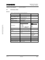
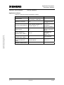
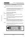
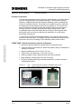
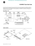
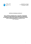
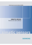
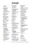
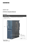
Application on Control Technology
SIMATIC S7 CPU 300/400
Application Description
Direction and Speed Detection of metallic Test Objects
in the S7-CPU Using inductive BEROs
Warranty, liability and support
Application inductive BEROs
Note
Entry ID: 22957673
The application examples are not binding and do not claim to be
complete regarding the circuits shown, equipping and any eventuality.
The application examples do not represent customer-specific solutions.
They are only intended to pro-vide support for typical applications. You
are responsible in ensuring that the de-scribed products are correctly
used. These application examples do not relieve you of the responsibility
in safely and professionally using, installing, operating and servicing
equipment. When using these application examples, you recognize that
Siemens cannot be made liable for any damage/claims beyond the
liability clause described. We reserve the right to make changes to these
application examples at any time without prior notice. If there are any
deviations between the recommendations provided in these application
examples and other Siemens publications - e.g. Catalogs - then the
contents of the other documents have priority.
Warranty, liability and support
Copyright © Siemens AG 2006 All rights reserved
22957673_Richtung_Geschwindigkeit_V20_e.doc
We do not accept any liability for the information contained in this
document.
Any claims against us - based on whatever legal reason - resulting from the
use of the examples, information, programs, engineering and performance
data etc., described in this application example shall be excluded. Such an
exclusion shall not apply in the case of mandatory liability, e.g. under the
German Product Liability Act (“Produkthaftungsgesetz”), in case of intent,
gross negligence, or injury of life, body or health, guarantee for the quality
of a product, fraudulent concealment of a deficiency or breach of a
condition which goes to the root of the contract (“wesentliche
Vertragspflichten”). However, claims arising from a breach of a condition
which goes to the root of the contract shall be limited to the foreseeable
damage which is intrinsic to the contract, unless caused by intent or gross
negligence or based on mandatory liability for injury of life, body or health
The above provisions does not imply a change in the burden of proof to
your detriment.
Copyright© 2006 Siemens A&D. It is not permissible to transfer or
copy these application examples or excerpts of them without first
having prior authorization from Siemens A&D in writing.
For questions about this document please use the following e-mail address:
mailto:[email protected]
V 1.0
01/27/06
2/55
Foreword
Application inductive BEROs
Entry ID: 22957673
Foreword
Objective of the application
This application was created to provide the user with the following:
•
•
A modifiable and expandable example of a detection of moving metallic
objects and
the illustration of a convenient option of operating and visualizing a
control using a touch panel.
This application shows how speed and conveying direction (forward /
reverse) of metallic objects or non-metallic objects with metal targets
(transport containers) are determined using a SIMATIC controller and three
inductive BEROs 1.
Copyright © Siemens AG 2006 All rights reserved
22957673_Richtung_Geschwindigkeit_V20_e.doc
•
This topic is particularly relevant in conveying and handling systems.
Main contents of this application
This application deals with the following key elements:
•
•
•
Design, principle of operation and application of inductive proximity
switches (BEROs)
STEP7 program of a speed and direction detection of material to be
conveyed or objects in a production process
Connection of a touch panel for operator control of the process and
plant monitoring using WinCC flexible
Delimitation
This application does not include a description of
•
•
the SIMATIC STEP 7 engineering tool
the WinCC flexible visualization software
Basic knowledge of these topics is required.
1
BERO = Sensor for the Contactless Recording of Objects
V 1.0
01/27/06
3/55
Foreword
Application inductive BEROs
Entry ID: 22957673
Structure of the document
The documentation of this application is divided into the following main
parts.
Copyright © Siemens AG 2006 All rights reserved
22957673_Richtung_Geschwindigkeit_V20_e.doc
Part
Description
Application Description
You are provided with a general overview of the
contents. You are informed on the used
components (standard hardware and software
components and the specially created user
software).
Principles of Operation
and Program Structures
This part describes the detailed functional
sequences of the involved hardware and software
components, the solution structures and – where
useful – the specific implementation of this
application. It is only required to read this part if you
want to familiarize with the interaction of the
solution components to use these components e.g.
as a basis for own developments.
Structure, Configuration
and Operation of the
Application
This part takes you step by step through structure,
important configuration steps, startup and operation
of the application.
Appendix
This part of the documentation includes further
information, e.g. bibliographic references,
glossaries, etc.
Reference to Automation and Drives Service & Support
This entry is from the internet application portal of Automation and Drives
Service & Support. The documentation has the entry ID 22957673. Click
the link below to directly display the download page of this document.
http://support.automation.siemens.com/WW/view/en/22957673
All entries referenced in this document are designated by their entry ID and
addressed via the above path.
V 1.0
01/27/06
4/55
Foreword
Application inductive BEROs
Entry ID: 22957673
Table of Contents
Application Description ............................................................................................... 6
1
1.1
1.2
Automation Problem ...................................................................................... 6
Overview........................................................................................................... 6
Requirements ................................................................................................... 8
2
2.1
2.2
2.2.1
2.2.2
2.3
2.4
Automation Solution .................................................................................... 10
Overview of the overall solution...................................................................... 10
Description of the core functionality................................................................ 11
Overview and description of the user interface............................................... 11
Sequence of the main functionality................................................................. 15
Required hardware and software components ............................................... 17
Performance data ........................................................................................... 20
Copyright © Siemens AG 2006 All rights reserved
22957673_Richtung_Geschwindigkeit_V20_e.doc
Principles of Operation and Program Structures .................................................... 22
3
3.1
General Function Mechanisms.................................................................... 22
Basics on “inductive sensors” ......................................................................... 22
4
4.1
4.2
4.2.1
4.2.2
4.2.3
4.2.4
Explanations on the Example Program ...................................................... 24
The structure of the STEP7 program .............................................................. 24
Detailed description of the individual software blocks .................................... 25
FB 1 (Direction and Speed Detection of Moving Objects) .............................. 26
FC 1 (Direction) .............................................................................................. 30
FC 2 (Speed) .................................................................................................. 31
DB 11 (DISPLAY&PARAM) ............................................................................ 32
5
5.1
5.1.1
5.1.2
5.2
5.3
5.3.1
5.3.2
5.4
Modifications to the Example Program (optional) ..................................... 33
Different BERO distances............................................................................... 33
Loading from sample project .......................................................................... 33
Modifying blocks yourself................................................................................ 34
Changing the flicker frequency ....................................................................... 36
Direction and speed detection with two BEROs ............................................. 38
Loading from sample project .......................................................................... 39
Modifying blocks yourself................................................................................ 40
Changing the runtime language (TP170A) ..................................................... 45
Structure, Configuration and Operation of the Application ................................... 46
6
6.1
6.2
6.3
Installation and Startup................................................................................ 46
Installation of hardware and software ............................................................. 46
Installation of the application software ............................................................ 47
Startup ............................................................................................................ 51
Appendix and Literature ............................................................................................ 54
7
V 1.0
Literature ....................................................................................................... 54
01/27/06
5/55
Application Description
Automation Problem
Application inductive BEROs
Entry ID: 22957673
Application Description
Content
You are provided with a general overview of the contents. You are informed
on the used components (standard hardware and software components
and the specially created user software).
The displayed performance data illustrate the performance capability of this
application.
1
Automation Problem
You are provided with information on…
Copyright © Siemens AG 2006 All rights reserved
22957673_Richtung_Geschwindigkeit_V20_e.doc
the specific automation problem described in this documentation.
1.1
Overview
Introduction
For the purpose of...
•
•
•
time coordination of sequential production steps of a production process
optimization of the conveying flow in a conveyor system (e.g. freight
center)
direction control of the material to be conveyed
it is required that speed and/or direction of motion of the material to be
conveyed are detected with contactless sensors. Using a PLC, this
information is used to control the conveying flow. An HMI (human machine
interface, e.g. a touch panel) enables to monitor the conveying flow and
direction decisions by operator inputs are possible.
Overview of the automation problem
The below figure shows an example of a possible field of application for this
application.
V 1.0
01/27/06
6/55
Application Description
Automation Problem
Application inductive BEROs
Entry ID: 22957673
Copyright © Siemens AG 2006 All rights reserved
22957673_Richtung_Geschwindigkeit_V20_e.doc
Figure 1-1: Field of application of sensors for process monitoring
Description of the automation problem
In a technical plant, a conveyor section is to be monitored, which can run in
both directions at different speeds. This is done to avoid disturbances of the
coordination in the interaction of different production steps. This requires
contactless detection of the containers transported on the conveyor
elements by sensors. Using the sensor signals, both the direction of motion
and the speed of the objects are to be determined and displayed on an
output device.
Figure 1-1 merely illustrates the rough topic of the application. The detail
problem of the speed and direction detection is illustrated in Figure 1-2. Not
reflex sensors as shown in the above figure but inductive BEROs are used
as sensors. Their robustness and insensitivity to dirt ensure reliable
operation also under harsh conditions and they are thus widely used in the
industrial field. However, this requires that the objects to be detected
consist of metal (at least partly) or that they have a metal target (special
transport containers) for the BERO detection.
To avoid misinterpretations during the object detection, not only two but
three sensors are to detect the passing objects. Direction and speed are
only determined after all three sensors have successively signaled the
object.
V 1.0
01/27/06
7/55
Application Description
Automation Problem
Application inductive BEROs
Entry ID: 22957673
Figure 1-2: Schematic view of the automation problem
BERO 1
BERO 2
BERO 3
s2 = s
reverse
forward
material to
be conveyed
s1 = s
conveyor section
s2 = s
tv
tR
Copyright © Siemens AG 2006 All rights reserved
22957673_Richtung_Geschwindigkeit_V20_e.doc
m = 2s
tBERO 1
1.2
tBERO 2
tBERO 3
s1 = s2 = s
tV
distance between BEROs
measured time with discharge direction "forward"
tR
m
measured time with discharge direction "reverse"
complete measuring distance
Requirements
This application is realized in a STEP7 project. It is to meet the
requirements listed below:
Sensor requirements
•
•
Metallic objects (material to be conveyed) which are to be conveyed
past the sensors are to be detected by them. If an object comes into the
detection range of a sensor, this causes a signal change from 0 to 1 at
the switching output of the sensor.
The sensors are to be designed as inductive proximity switches
(BEROs).
Controller requirements
•
•
•
V 1.0
Using the sensor signals, direction and speed of the material to be
conveyed are to be determined if the conveyor section is switched on.
Each object detection is to be provided with a time stamp.
Depending on the last determined current direction, a corresponding
digital output is to be controlled (flashing).
01/27/06
8/55
Application Description
Automation Problem
Application inductive BEROs
•
Entry ID: 22957673
If no further object passes all three sensors within a variable time after
an object detection, the displays on the HMI (direction display, speed)
and the respective digital output (flashing direction display) of the
controller are to be reset.
HMI requirements
•
Copyright © Siemens AG 2006 All rights reserved
22957673_Richtung_Geschwindigkeit_V20_e.doc
•
•
Note
V 1.0
The HMI is to be realized by a touch panel (screen diagonal 6 inches).
The following information is to be displayed:
– The direction of the material to be conveyed (forward/reverse)
–
The speed of the material to be conveyed (in m/s)
–
The time stamp of the last object detection
–
Mode of the conveyor section (ON/OFF)
–
Status of the direction detection (enabled/disabled)
–
Status of the speed detection (enabled/disabled)
The following operations are to be possible:
– Enabling/disabling the direction detection
–
Enabling/disabling the speed detection
–
Terminating the runtime
–
Entering the sensor distance
–
Entering the display duration
The above-mentioned requirements are met by the application software
without need for additional programming overhead or entering
parameters in data blocks.
01/27/06
9/55
Application Description
Automation Solution
Application inductive BEROs
2
Entry ID: 22957673
Automation Solution
You are provided with information on…
the solution selected for the automation problem.
2.1
Overview of the overall solution
Diagrammatic representation
The following figure schematically shows the most important components of
the solution:
Copyright © Siemens AG 2006 All rights reserved
22957673_Richtung_Geschwindigkeit_V20_e.doc
Figure 2-1: Hardware overview of the automation solution
Structure
A SIMATIC CPU 314C-2 DP is the key element of the application. This
central processing unit already includes the digital inputs and outputs
required by the application. The switching outputs of the three inductive
BEROs are directly connected to the three digital inputs integrated in the
V 1.0
01/27/06
10/55
Application Description
Automation Solution
Application inductive BEROs
Entry ID: 22957673
central processing unit. The TP170A touch panel is connected to the MPI of
the controller via a PROFIBUS cable. The controller and the BEROs as well
as the touch panel are supplied with 24V DC by the PS 307 power supply.
2.2
Description of the core functionality
2.2.1
Overview and description of the user interface
A TP 170A touch panel is primarily used as HMI. The display/HMI is
realized by three screens:
•
Start screen (main screen)
•
Releases screen
•
Parameters screen
Copyright © Siemens AG 2006 All rights reserved
22957673_Richtung_Geschwindigkeit_V20_e.doc
In addition, the passing of the BEROs is displayed by optional flickering of
two digital output bits (forward, reverse).
TP 170A – Start screen
Figure 2-2: Start screen
Provided that the touch panel has already been loaded with the HMI
software created in WinCC flexible, the above start screen – which at the
same time is to be considered as main screen – is displayed when applying
the supply voltage. The following data are displayed:
V 1.0
01/27/06
11/55
Application Description
Automation Solution
Application inductive BEROs
Entry ID: 22957673
1. Direction
A direction detection is only performed if it is enabled (see “Releases
screen”) and if the conveyor section is in operation. As soon as an
object has been detected by all three sensors, its conveying direction is
indicated by an “X” in the corresponding box. After a defined display
duration has elapsed (see “Parameters screen”), the “X” disappears.
For the definition of the terms “forward” and “reverse” see Figure 1-2. If
the connection to the PLC fails, the display is no longer updated and
keeps the last status (“ “ or “X”).
Copyright © Siemens AG 2006 All rights reserved
22957673_Richtung_Geschwindigkeit_V20_e.doc
2. Last Registration
If the conveyor section runs and if the direction detection is enabled
(see “Releases screen”), the last object passing the three BEROs is
provided with a direction-dependent time stamp. The time is from the
PLC clock. Another object with the same conveying direction overwrites
the time stamp. “###...“ is displayed if there is no connection to the
PLC. The time stamps of both conveying directions are updated during
the STOPÆRUN transition of the PLC.
3. conveyor section:
The mode is displayed (ON = conveyor is running / OFF = conveyor is
not running). If the connection to the PLC fails, the display is no longer
updated and keeps the last status (“ON“ or “OFF”)
4. actual speed [m/s]:
A speed detection is only performed if the conveyor section is in
operation. As soon as an object has passed all three sensors, the
determined speed is displayed. After a defined display duration has
elapsed (see “Parameters screen”), the speed display is reset to
“0.000”. If there is no connection to the PLC, “#####” is displayed.
5. Direction Detection
It is displayed whether the direction detection is “disabled” or “enabled”
(see “Releases screen”). The direction is only displayed according to
point 1 if the direction detection is enabled. If the connection to the PLC
fails, the display is no longer updated and keeps the last status
(“disabled” or “enabled”).
6. Speed Detection
It is displayed whether the speed detection is “disabled” or “enabled”
(see “Releases screen”). The speed is only displayed according to point
4 if the speed detection is enabled. If the connection to the PLC fails,
the display is no longer updated and keeps the last status (“disabled” or
“enabled”).
Three buttons to call additional screens are located at the bottom of the
display:
V 1.0
01/27/06
12/55
Application Description
Automation Solution
Application inductive BEROs
Entry ID: 22957673
1. releases
Use this button to branch to the “Releases screen” for the
enable/disable of the direction and speed display.
2. parameters
Use this button to branch to the “Parameters screen” for defining the
sensor distances and the display duration.
3. stop runtime
Use this button to terminate the application on the touch panel and to
call its start menu.
TP 170A – Releases screen
Copyright © Siemens AG 2006 All rights reserved
22957673_Richtung_Geschwindigkeit_V20_e.doc
Figure 2-3: Releases screen
Use the “releases” button in the “start screen” to display the “Releases
screen”.
1. Direction Detection
Use the “enable/disable” button to activate or deactivate the direction
detection. The box to the right of the button displays the selected mode
and is identical to the corresponding display in the start screen.
2. Speed Detection
Use the “enable/disable” button to activate or deactivate the speed
detection. The box to the right of the button displays the selected mode
and is identical to the corresponding display in the start screen.
V 1.0
01/27/06
13/55
Application Description
Automation Solution
Application inductive BEROs
Entry ID: 22957673
Use the back button located at the bottom of the display to return to the
start screen.
TP 170A – Parameters screen
Copyright © Siemens AG 2006 All rights reserved
22957673_Richtung_Geschwindigkeit_V20_e.doc
Figure 2-4: Parameters screen
Use the “parameters” button in the “start screen” to display the “Parameters
screen”. When selecting (touching) the respective I/O box, a numerical
keyboard is displayed on the screen with which you can enter the desired
value and apply it using the Enter key.
1. Sensor Distance
Enter the distance between the BEROs according to Figure 1-2. The
application can operate with values between 0.0 and +99.9. Negative
values are converted to positive values when entered. Values >99.9 are
limited to +99.9.
2. Display Period
You enter the time after which a direction and/or speed display is to be
reset on the display. The application can operate with values between 0
and +60. Negative values are converted to positive values when
entered. Values >60 are limited to +60.
Use the back button located at the bottom of the display to return to the
start screen.
V 1.0
01/27/06
14/55
Application Description
Automation Solution
Application inductive BEROs
Entry ID: 22957673
LED displays
Aside from the visualization on the TP170A, the last detected direction is
indicated by optional flickering (fast flashing) by two digital outputs.
•
Conveying direction forward:
A 4.0
•
Conveying direction reverse:
A 4.1
The duration of the flickering corresponds to the display duration. The
digital outputs could e.g. be used to control indicator lights.
2.2.2
Sequence of the main functionality
Copyright © Siemens AG 2006 All rights reserved
22957673_Richtung_Geschwindigkeit_V20_e.doc
The following flowchart illustrates the core functionality “detection of
direction and speed”. It refers to the time and path designations in
Figure 1-2. It is assumed that direction and speed detection are enabled.
V 1.0
01/27/06
15/55
Application Description
Automation Solution
Application inductive BEROs
Entry ID: 22957673
Figure 2-5: Flowchart of the core functionality
start
N
timer for display period elapsed?
Y
reset display for direction and speed
N
positive edge at BERO 2?
Y
save time stamp tBERO 2
Copyright © Siemens AG 2006 All rights reserved
22957673_Richtung_Geschwindigkeit_V20_e.doc
set detection flag of BERO 2
N
positive edge at BERO 1?
Y
detection flag of BERO 2 and BERO 3
already set?
Y
N
Y
display "reverse" with time stamp tBERO 1
calculate and display speed v = s/tR
detection flag of BERO 2 already set,
but not of BERO 3?
N
start / retrigger display period
set detection flag of BERO 1
reset detection flags of BERO 2 and BERO 3
N
positive edge at BERO 3?
Y
detection flag of BERO 2 and BERO 1
already set?
Y
N
Y
detection flag of BERO 2 already set,
but not of BERO 1?
N
display "forward" with time stamp tBERO 3
calculate and display speed v = s/tV
start / retrigger display period
set detection flag of BERO 3
reset detection flags of BERO 2 and BERO 1
events
end
V 1.0
01/27/06
16/55
Application Description
Automation Solution
Application inductive BEROs
2.3
Entry ID: 22957673
Required hardware and software components
The application was developed and tested with the following components.
Please consider that configuration changes in the sample project are
possibly required in case of deviations from the listed components and that
screen shots in this document can differ from your screen contents.
To realize the sample project, you additionally require:
•
PG or PC with corresponding communications processor (e.g. CP5512)
and Microsoft ® Windows 2000 Professional or Windows XP
Professional operating system.
•
An MPI cable.
Hardware components
Table 2-1: Hardware components
Copyright © Siemens AG 2006 All rights reserved
22957673_Richtung_Geschwindigkeit_V20_e.doc
Component
MLFB / Order number
Note
SIMATIC S7-300,
RAIL L=480MM
1
6ES7390-1AE80-0AA0
= minimum length
SIMATIC S7-300,
LOAD POWER SUPP.
PS 307, AC 120/230V,
DC 24V, 2A
1
6ES7307-1BA00-0AA0
Or similar power
supply
SIMATIC S7-300,
CPU 314C-2 DP
COMPACT
1
6ES7314-6CF02-0AB0
The compact
version was only
used because of
the integrated
DO/DI.
SIMATIC S7,
MICRO MEMORY CARD
F. S7-300/C7/ET 200S
IM151 CPU, 3,3 V
NFLASH, 64 KBYTE
6ES7953-8LF11-0AA0
Or larger
SIMATIC S7-300,
FRONT CONNECTOR
392 WITH SCREW
CONTACTS, 40-PIN
6ES7392-1AM00-0AA0
Also available with
spring contacts
6AV6545-0BA15-2AX0
Configurable with
ProTool/Lite from
version V5.2, SP1
and WinCC flexible
Compact from
version 2004
SIMATIC TOUCHPANEL
TP170A BLUE MODE
STN-DISPLAY
MPI/PROFIBUS-DP INTERFACE
V 1.0
No.
1
01/27/06
17/55
Application Description
Automation Solution
Application inductive BEROs
Entry ID: 22957673
Copyright © Siemens AG 2006 All rights reserved
22957673_Richtung_Geschwindigkeit_V20_e.doc
Component
No.
MLFB / Order number
Note
SIMATIC NET, CONN.
CABLE 830-2 F.
PROFIBUS,
PREASSEMBLED
CABLE WITH 2 SUB-DCONNECTORS 9-POLE,
SWITCHABLE
TERMINATING
RESISTORS, 3 M
1
6XV1830-2AH30
2-wire shielded
cable with
PROFIBUS
connectors for
connecting the TP
170A to the CPU.
For alternatives see
/6/.
PROXIMITY SWITCH
BERO CUBIC 40 MM X
40 MM INDUCTIVE,
15...34 V DC, SN=15
MM, FLUSH, NO+NC,
200 MA, PNP, 4-WIRE,
MOLD. PLASTIC,
SHORTY, SENSOR
ADJUSTABLE IN 5 DIR.,
WITH M12 CONN.
ROTATABLE, IP67
3
3RG4038-3CD00
Or equivalent
inductive proximity
switch
M12 ANGLED CABLE
PLUG, 4-POL. WITH 5M
CABLE PUR BLACK, 4 X
0.34MM2
3
3RX8000-0CE42-1AF0
Or equivalent
component
Standard software components
Table 2-2: Standard software components
Component
V 1.0
No.
MLFB / Order number
Note
SIMATIC S7, STEP7
V5.3, FLOATING
LICENSE FOR 1 USER,
E-SW, SW AND DOCU.
ON CD, LICENSE KEY
ON FD, CLASS A,
5 LANGUAGES
(G,E,F,I,S),
EXECUTABLE UNDER
WIN2000PROF/XPPROF
REFERENCE-HW: S7300/400, C7
1
6ES7810-4CC07-0YA5
For sources for
Service Pack 3 see
/7/.
WINCC FLEXIBLE 2005
COMPACT
ENGINEERING-SW,
FLOATING LICENSE
LICENSE KEY ON FD
SW AND
DOCUMENTATION ON
CD IN
GER/EN/IT/FR/SP,
EXEC. UNDER
WIN2000/XPPROF FOR
CONFIGURATION OF
SIMATIC PANELS UPTO
SERIES 170
1
6AV6611-0AA01-1CA5
TP170A requires at
least WinCC flexible
Compact.
01/27/06
18/55
Application Description
Automation Solution
Application inductive BEROs
Entry ID: 22957673
Example files and projects
The following list contains all files and projects used in this example.
Table 2-3: Example files and projects
Component
BIDxyz_Richtg_Geschw_V20_e.zip
This zip file contains the
STEP 7 project.
The visualization with the aid of a touch panel is integrated in the STEP7
project. The “direction and speed detection” functionality is also complied
with without visualization.
Copyright © Siemens AG 2006 All rights reserved
22957673_Richtung_Geschwindigkeit_V20_e.doc
Note
Note
V 1.0
01/27/06
19/55
Application Description
Automation Solution
Application inductive BEROs
2.4
Entry ID: 22957673
Performance data
Sensors
Table 2-4: Data of the proximity switch 3RG4038-3CD00
Feature
Data/notes
Operating voltage
15...34 V DC
No-load supply current Io
Max. 30 mA (24 V)
Max. 40 mA (34 V)
Rated operational
current Ie
200 mA ( ≤ 50°C)
150 mA (≤ 85°C)
Enclosure material
Molded plastic
Design
Cubic 40 mm x 40 mm
4 lines (connector M12):
Copyright © Siemens AG 2006 All rights reserved
22957673_Richtung_Geschwindigkeit_V20_e.doc
Connections
V 1.0
1 Æ Plus
3 Æ Mass
4 Æ Signal (make contact
element)
Comment
Colors
(connection lines):
Brown
Blue
Black
Switching type
PNP
Display
LED green ÆPower supply
LED yellowÆSwitching status
Rated operating distance
sn
15 mm
+/- 10 %
Buttability
75 mm (center to center)
Otherwise mutual
disturbance
possible
Switching frequency f
50 Hz
Repeat accuracy R
0.75 mm
Power-up delay tv
100 ms
Degree of protection
IP 67
Operating temperature
-25°C to 85°C
01/27/06
20/55
Application Description
Automation Solution
Application inductive BEROs
Entry ID: 22957673
Application software
Copyright © Siemens AG 2006 All rights reserved
22957673_Richtung_Geschwindigkeit_V20_e.doc
Table 2-5: Performance data of the application software
V 1.0
Criterion
Performance data
Program size
MMC:
6086 bytes
Main memory: 4200 bytes
Maximum cycle time
3 ms
For CPU according
to Table 2-1
Minimum object distance
Entire measuring distance “m”
(compare Figure 1-2)
Only one object
permitted in
measuring distance
Object length
Any
Object must be
securely detected by
BERO.
Sensor distance “s”
(default value in DB11)
25.0 cm
User parameter
(compare
Figure 1-2)
Display duration
(default value in DB11)
5s
User parameter
Resolution of the speed
display on the touch
panel
3 decimal places
Unit: m / s
Number of HMI screens
3
01/27/06
Additional note
21/55
Principles of Operation and Program Structures
General Function Mechanisms
Application inductive BEROs
Entry ID: 22957673
Principles of Operation and Program Structures
Content
This part describes the detailed functions and functional sequences of the
involved hardware and software components, the solution structures and –
where useful – the specific implementation of this application.
It is only required to read this part if you are interested in details on the
solution components and their interaction.
3
General Function Mechanisms
You are provided with information on…
Copyright © Siemens AG 2006 All rights reserved
22957673_Richtung_Geschwindigkeit_V20_e.doc
the general function mechanisms which apply with regard to BEROs.
3.1
Basics on “inductive sensors”
To provide also readers with little or no experience in sensor technology
with an introduction to the topic, some basic information on “inductive
sensors” will be listed in the following.
Brief description
Inductive proximity switches are used to detect positions of metallic parts
and to convert them into electrical signals. These signals are further
processed in controlling and signaling equipment (PLC). The output signals
from the PLC can then trigger actions such as switching a contactor.
Design
An inductive proximity switch basically consists of a coil, a ferrite core and
connected electronics (figure 1-1). These elements are enclosed densely
and immune to vibrations in a housing.
Figure 3-1: Schematic representation of an inductive proximity switch
V 1.0
01/27/06
22/55
Principles of Operation and Program Structures
General Function Mechanisms
Application inductive BEROs
Entry ID: 22957673
Principle of operation
The electronics generate a high-frequency signal which is converted by the
coil into a magnetic field of the same frequency. The electronic setup is
based on a dampened electrical oscillator switching circuit containing the
coil as an oscillator element. The ferrite core is shaped in such a way that
the largest part of the magnetic field lines is guided in it. The core is only
open in measuring direction so that the magnetic field lines can exit the
housing and form a measuring field before the proximity switch. With
increasing distance from the switch the flux density of the magnetic field
decreases more and more so that also the sensitivity for a test object
decreases continuously.
If a test object is within the switching distance, the magnetic field induces
currents in the test object. The effects of these currents are detected by the
electronics and cause a change of the switching status of the sensor.
“BERO 3RG4” inductive proximity switches by Siemens
Copyright © Siemens AG 2006 All rights reserved
22957673_Richtung_Geschwindigkeit_V20_e.doc
• Inductive proximity switches operate without mechanical wear.
• Types for damp environments or with IP 68 plastic casing if resistance to
welding is required.
• Switching distances from 0.6 mm to 75 mm
• Types from 3 mm diameter to 100 x 80 x 40 mm
• Casing of plastic, brass, stainless steel and other materials
• High reliability, maintenance-free over a long life
• Pin-point switching with high operating speed also in case of extreme
switching frequency
Figure 3-2:
V 1.0
Left:
right:
Inductive proximity switches of the BERO 3RG4 series
BERO 3RG4038-3CD00 (used in this application)
01/27/06
23/55
Principles of Operation and Program Structures
Explanations on the Example Program
Application inductive BEROs
4
Entry ID: 22957673
Explanations on the Example Program
You are provided with information on…
4.1
•
the structure of the STEP7 program
•
the functions of the individual blocks and networks
The structure of the STEP7 program
Figure 4-1: Structure of the STEP7 program
OB 100
SFC 20
FC 1
Copyright © Siemens AG 2006 All rights reserved
22957673_Richtung_Geschwindigkeit_V20_e.doc
operating system
SFC 20
DB 1
OB 1
FB 1
DB 11
SFC 1
FC 2
FC 34
organisation blocks
data blocks
function blocks
instance data blocks
user functions
library functions
system functions
The block architecture of the STEP7 operating system ensures the
structuredness of the program.
V 1.0
01/27/06
24/55
Principles of Operation and Program Structures
Explanations on the Example Program
Application inductive BEROs
Entry ID: 22957673
Table 4-1: Used software blocks
Copyright © Siemens AG 2006 All rights reserved
22957673_Richtung_Geschwindigkeit_V20_e.doc
Block
4.2
Explanation
OB 1
Organization block (called by the operating system) for the cyclic
program processing. It calls the user function block FB1.
OB 100
Organization block (called by the operating system) which is
processed when restarting the CPU. The block ensures that the
“Last Registration” boxes of the HMI start screen are preset with the
time stamp of the restart during the restart. The time stamp is
transferred from the OB100 local data (start information of the block,
see OB100 online help) to DB11 by means of the SFC20 BLKMOV
system function.
FB 1
This user function block is the main program of the application. It
includes the logic for…
• the direction and speed detection with call of the functions FC1
and FC2.
• the display duration.
• the calls of SFC1 READ_CLK for the event-controlled reading of
the CPU clock.
• the direction display via the digital outputs.
DB 1
Instance DB for FB 1. The block is used as buffer for edge, pulse,
status flags and for the buffering of the time stamps.
FC 1
This user function realizes the direction display with time stamp.
FC 2
This user function realizes the speed calculation. The FC34 library
function is called, which creates a time stamp difference.
FC34
The library function (from standard library / IEC function blocks)
subtracts two time stamps and a period as a result. See FC34
online help.
DB 11
Interface DB to the touch panel for the data to be displayed or the
user parameters to be entered.
SFC 1
System function (implemented in the CPU) for reading the CPU
clock. See SFC1 online help.
SFC 20
System function (implemented in the CPU) for copying a memory
area. In this application, SFC20 is used to transfer the time stamps.
See SFC20 online help.
Detailed description of the individual software blocks
The detailed description refers to the STEP7 project of which all symbols
and comments were created in English. To provide a clear reference to the
program code, headings, variable names, etc. were not translated in the
following sections.
The blocks not described in the following are self-explanatory when viewing
their program code. The brief information in the above table provides an
adequate explanation.
V 1.0
01/27/06
25/55
Principles of Operation and Program Structures
Explanations on the Example Program
Application inductive BEROs
4.2.1
Entry ID: 22957673
FB 1 (Direction and Speed Detection of Moving Objects)
The block has 9 networks.
Table 4-2: Detailed description of FB 1
NW
1
Explanation
Parameter Check
•
•
The value for the display duration
(“DISPLAY&PARAM”.display_period) to be entered in the
“Parameters” HMI screen is checked for plausibility. If the value is
negative, the sign is truncated (by two’s complement generation). If
the value >60 (sec), the value is limited to 60.
The value for the BERO distance
(“DISPLAY&PARAM”.BERO_distance) to be entered in the
“Parameters” HMI screen is checked for plausibility. If the value is
negative, the sign is truncated (ABS command). If the value >99.9
(cm), the value is limited to 99.9.
Copyright © Siemens AG 2006 All rights reserved
22957673_Richtung_Geschwindigkeit_V20_e.doc
The values possibly changed as described above are written to the
respective same variable and thus displayed on the touch panel.
2
Timer for Display Period
When calling FB 1 for the first time, a timer is started with the display
duration (“DISPLAY&PARAM”.display_period) defined by the user in the
“Parameters” HMI screen. A timer restart is subsequently only possible by
an explicit enable. In the further course of the program this enable is given
whenever one of the BEROs signals an object in the monitored space (see
networks 4 and 5). If this is not the case and if the timer elapses, the
update IDs (“IDB”.DIR_update, .SPEED_update) causing a call of the
functions FC1 and FC2 are set. The object ID also set at this location
(“IDB”.no_object) ensures that FC1/FC2 reset the direction displays and
the speed value in DB11
(“DISPLAY&PARAM”.forward, .reverse, .speed).
3
Positive Edge at BERO 2
If BERO 2 detects a positive edge,
• the time stamp used as starting point for the speed measurement
(“IDB”.timestamp_start) is written into the instance DB.
• an event ID (“IDB”.BERO2_object_detected) is set.
• the object ID (“IDB”.no_object) is reset.
V 1.0
01/27/06
26/55
Principles of Operation and Program Structures
Explanations on the Example Program
Application inductive BEROs
Entry ID: 22957673
NW
4
Explanation
Positive Edge at BERO 1
Copyright © Siemens AG 2006 All rights reserved
22957673_Richtung_Geschwindigkeit_V20_e.doc
If BERO 1 detects a positive edge, the object ID (“IDB”.no_object) is reset
and the following procedure takes place. If no edge is detected, a jump to
the next network occurs.
If the object has already passed BERO 3 and BERO 2
(“IDB”.BERO3_object_detected, .BERO2_object_detected),
• the timer for the display duration is started.
• the update ID for the direction (“IDB”.DIR_update) is set.
• the update ID for the speed is set (“IDB”.SPEED_update) provided
that the conveyor was not switched off or disturbed
(“IDB”.conv_temp_off) while the object was moving from BERO 2 to
BERO 1. If the conveyor was interrupted, the running ID
("IDB".conv_temp_off) is reset.
• the time stamp used as target for the speed measurement (“IDB”.timestamp_stop) is written into the instance DB.
• the detection ID for BERO 1 (“IDB”.BERO1_object_detected) is set.
• the detection IDs for BERO 3 and BERO 2
(“IDB”.BERO3_object_detected, .BERO2_object_detected) are reset.
If the object has passed BERO 2 but not BERO 3,
• the detection IDs for BERO 2
(“IDB”.BERO2_object_detected) are reset.
If the object has passed BERO 3 but not BERO 2,
• the detection IDs for BERO 3
(“IDB”.BERO3_object_detected) are reset.
• the detection ID for BERO 1 (“IDB”.BERO1_object_detected) is set.
V 1.0
01/27/06
27/55
Principles of Operation and Program Structures
Explanations on the Example Program
Application inductive BEROs
Entry ID: 22957673
NW
5
Explanation
Positive Edge at BERO 3
If BERO 3 detects a positive edge, the object ID (“IDB”.no_object) is reset
and the following procedure takes place. If no edge is detected, a jump to
the next network occurs.
Copyright © Siemens AG 2006 All rights reserved
22957673_Richtung_Geschwindigkeit_V20_e.doc
If the object has already passed BERO 1 and BERO 2
(“IDB”.BERO1_object_detected, .BERO2_object_detected),
• the timer for the display duration is started.
• the update ID for the direction (“IDB”.DIR_update) is set.
• the update ID for the speed is set (“IDB”.SPEED_update) provided that
the conveyor was not switched off or disturbed (“IDB”.conv_temp_off)
while the object was moving from BERO 2 to BERO 3. If the conveyor
was interrupted, the running ID ("IDB".conv_temp_off) is reset.
• the time stamp used as target for the speed measurement (“IDB”.timestamp_stop) is written into the instance DB.
• the detection ID for BERO 3 (“IDB”.BERO3_object_detected) is set.
• the detection IDs for BERO 1 and BERO 2
(“IDB”.BERO1_object_detected, .BERO2_object_detected)
are reset.
If the object has passed BERO 2 but not BERO 1,
• the detection ID for BERO 2 (“IDB”.BERO2_object_detected)
is reset.
If the object has passed BERO 1 but not BERO 2,
• the detection ID for BERO 1 (“IDB”.BERO1_object_detected) is reset.
• the detection ID for BERO 3 (“IDB”.BERO3_object_detected) is set.
6
Call FC1 (Detecting Direction)
The block for the direction detection is called if the user has given the
respective enable (“DISPLAY&PARAM”.release_direction) in the
“Releases” HMI screen and if the corresponding update ID
(“IDB”.DIR_update) was set in network 4 or 5. When removing the enable,
the direction displays
(“DISPLAY&PARAM”.forward, .reverse) on the “Information” HMI screen
are reset immediately.
V 1.0
01/27/06
28/55
Principles of Operation and Program Structures
Explanations on the Example Program
Application inductive BEROs
Entry ID: 22957673
NW
7
Explanation
Call FC2 (Calculating Speed)
The block for the speed detection is called if the user has given the
respective enable (“DISPLAY&PARAM”.release_speed) in the “Releases”
HMI screen and if the corresponding update ID (“IDB”.SPEED_update)
was set in network 4 or 5. When removing the enable, the speed display
(“DISPLAY&PARAM”.speed) on the “Information” HMI screen is
immediately overwritten with 0.000.
8
No Speed Detecting with Conveyor Stop
If the conveyor is switched off or disturbed (conveyor_on = E0.5 = 0) while
the object is located between two BEROs of the measuring device, thus if
the detection IDs BERO 1 / BERO 2 or the detection IDs BERO 2 / BERO
3 are both set, the running ID (“IDB”.conv_temp_off) is set.
Copyright © Siemens AG 2006 All rights reserved
22957673_Richtung_Geschwindigkeit_V20_e.doc
9
Flickering Outputs
While the “display_timer” is active, the direction of an object is indicated by
a flickering (5Hz) of the digital outputs “flickering_fwd” or “flickering_rev”.
This flickering is achieved by the logic operation (AND) of the direction ID
(“DISPLAY&PARAM”.forward, .reverse) and M 0.1 (clock_memory_bit).
V 1.0
01/27/06
29/55
Principles of Operation and Program Structures
Explanations on the Example Program
Application inductive BEROs
4.2.2
Entry ID: 22957673
FC 1 (Direction)
Table 4-3: Detailed description of FC 1
NW
1
Explanation
Detect Direction
The update ID (“IDB”.DIR_update) which caused the call of the FC is
unconditionally reset.
If no object is located in the range of the measuring device (“ID”.no_object)
or if the conveyor is not running (conveyor_on = E0.5 = 0), the direction
displays (“DISPLAY&PARAM”.forward, .reverse) and the update ID
(“IDB”.DIR_update) are reset and the block is exited.
Copyright © Siemens AG 2006 All rights reserved
22957673_Richtung_Geschwindigkeit_V20_e.doc
If the detection ID for BERO 1 is set (“IDB”.BERO1_object_detected),
which means that an object has just passed BERO 1 in reverse direction,
the time stamp read out in NW4 of FC1 (“IDB”.timestamp_stop) is
transferred to DB11 (“DISPLAY&PARAM”.timestamp_rev) by means of the
BLKMOV function and provided to the HMI for the “Last Registration /
reverse” display. The direction display for “forward”
(“DISPLAY&PARAM”.forward) is reset, the display for “reverse”
(“DISPLAY&PARAM”.reverse) is set.
If the detection ID for BERO 3 is set (“IDB”.BERO3_object_detected),
which means that an object has just passed BERO 3 in forward direction,
the time stamp read out in NW5 of FC1 (“IDB”.timestamp_stop) is
transferred to DB11 (“DISPLAY&PARAM”.timestamp_fwd) by means of
the BLKMOV function and provided to the HMI for the “Last Registration /
forward” display. The direction display for “reverse”
(“DISPLAY&PARAM”.reverse) is reset, the display for “forward”
(“DISPLAY&PARAM”.forward) is set.
V 1.0
01/27/06
30/55
Principles of Operation and Program Structures
Explanations on the Example Program
Application inductive BEROs
4.2.3
Entry ID: 22957673
FC 2 (Speed)
Table 4-4: Detailed description of FC 2
NW
1
Explanation
Calculate Speed
The update ID (“IDB”.SPEED_update) which caused the call of the FC is
unconditionally reset.
If no object is located in the range of the measuring device (“ID”.no_object)
or if the conveyor is not running (conveyor_on = E0.5 = 0), the displayed
speed value
(“DISPLAY&PARAM”.speed) is overwritten with 0.000 and the block is
exited.
Copyright © Siemens AG 2006 All rights reserved
22957673_Richtung_Geschwindigkeit_V20_e.doc
If the above condition is not complied with, which means that an object has
just passed either BERO 1 in reverse or BERO 3 in forward direction,
FC34 is used to determine the time difference from the time stamps of the
two last passed BEROs (“IDB”.timestamp_stop, .timestamp_start). This
time difference is in the “TIME” format and it is subsequently converted to
seconds. The speed displayed on the “Information” HMI screen is the
quotient of the – converted from cm to m – BERO distance
(“DISPLAY&PARAM”.BERO_distance) which can be entered by the user
in the “Parameters” HMI screen and the above time difference.
V 1.0
01/27/06
31/55
Principles of Operation and Program Structures
Explanations on the Example Program
Application inductive BEROs
4.2.4
Entry ID: 22957673
DB 11 (DISPLAY&PARAM)
The figure below shows the correlation between the data in DB 11 and the
HMI screens.
Copyright © Siemens AG 2006 All rights reserved
22957673_Richtung_Geschwindigkeit_V20_e.doc
Figure 4-2: Data of DB11 (DISPLAY&PARAM) in the HMI screens
V 1.0
01/27/06
32/55
Principles of Operation and Program Structures
Modifications to the Example Program (optional)
Application inductive BEROs
5
Entry ID: 22957673
Modifications to the Example Program (optional)
You are provided with information on…
what you have to do if…
5.1
•
the BERO distances cannot be kept equal.
•
you want a different flicker frequency.
•
you prefer a solution with two BEROS.
•
you want to change the runtime language on the TP170A.
Different BERO distances
Copyright © Siemens AG 2006 All rights reserved
22957673_Richtung_Geschwindigkeit_V20_e.doc
Solution principle
If the objects move in forward direction, the speed is measured between
BEROs 2 and 3; if the objects move in reverse direction, the measurement
takes place between 2 and 1. For the definition of the direction, see Figure
1-2. As the direction detection in FC1, the speed detection in FC2 also has
to be performed direction-dependently.
Changes
The modified functionality requires that the blocks FC2, FB1 and DB11 are
changed. Since now two BERO distances have to entered on the touch
panel, the HMI configuration also changes.
We offer you two types of program change:
1. Loading from sample project
2. Modifying blocks yourself
5.1.1
Loading from sample project
The program with the modified blocks is located in the “Diff_Dist” program
folder of the STEP7 project.
1. Copy the entire content of “Diff_Dist” to the “S7 program” program
folder in the SIMATIC station.
2. Load the entire station to the CPU
(to avoid inconsistencies, we recommend loading the complete station
or at least all user blocks and not only the modified blocks.)
3. Load the WinCC flexible project which is also named
“Diff_Dist” to the touch panel.
V 1.0
01/27/06
33/55
Principles of Operation and Program Structures
Modifications to the Example Program (optional)
Application inductive BEROs
5.1.2
Entry ID: 22957673
Modifying blocks yourself
Alternatively, you can also use the instructions below to modify the blocks
step by step (starting from the program and the “Equ_Dist” HMI
configuration). Proceed as follows:
4. Enter a second BERO distance for DB11.
Figure 5-1: Change in DB11 (DISPLAY&PARAM)
Copyright © Siemens AG 2006 All rights reserved
22957673_Richtung_Geschwindigkeit_V20_e.doc
5. Insert IN parameters for the BERO detection IDs of the two directions in
FC2 and change the FC2 program code.
Figure 5-2: Changes in FC2 (SPEED)
V 1.0
01/27/06
34/55
Principles of Operation and Program Structures
Modifications to the Example Program (optional)
Application inductive BEROs
Entry ID: 22957673
6. Make the following changes in FB1:
Network 1:
The check of the entry value has to be entered for the second BERO
distance.
Copyright © Siemens AG 2006 All rights reserved
22957673_Richtung_Geschwindigkeit_V20_e.doc
Figure 5-3: Check of the entry value for the second BERO distance
Network 6:
Update the FC2 call.
Figure 5-4: FC2 call update in FB1
7. Use WinCC flexible to enter the second BERO distance in the
“Parameters” HMI screen. The variables to be connected for the BERO
distances are “DISPLAY&PARAM.BERO_distance_12” and
“DISPLAY&PARAM.BERO_distance_23”.
V 1.0
01/27/06
35/55
Principles of Operation and Program Structures
Modifications to the Example Program (optional)
Application inductive BEROs
Entry ID: 22957673
Copyright © Siemens AG 2006 All rights reserved
22957673_Richtung_Geschwindigkeit_V20_e.doc
Figure 5-5: Parameters screen with option to enter different BERO distances
8. Load the modified blocks to the CPU and the changed HMI
configuration to the touch panel.
5.2
Changing the flicker frequency
Solution principle
The CPU provides a clock memory byte with eight bits of which the signal
status changes periodically with a pulse-pause ratio of 1:1. The bits
represent eight different frequencies.
V 1.0
01/27/06
36/55
Principles of Operation and Program Structures
Modifications to the Example Program (optional)
Application inductive BEROs
Entry ID: 22957673
Figure 5-6: Clock memory byte
7
6
5
4
3
2
1
0
10 Hz
5 Hz (flickering)
2,5 Hz (fast blinking)
2 Hz
1,25 Hz (blinking)
Copyright © Siemens AG 2006 All rights reserved
22957673_Richtung_Geschwindigkeit_V20_e.doc
1 Hz
0,625 Hz (slow blinking)
0,5 Hz
One of these bits (M 0.1, clock_memory_bit) is used by the user program to
generate the flicker frequency of the digital outputs flickering_fwd or
flickering_rev. You can change the frequency by using one of the other
eight clock memory bits.
Note
The clock memory byte is activated and assigned in HW Config in the
object properties of the CPU under “Cycle/Clock Memory”.
Changes
In the following the flicker frequency is to be reduced from 5 Hz to 2.5 Hz.
1. Open the symbol table
Figure 5-7: Opening the symbol table
2. Assign the address M 0.2 (previously M 0.1) to the clock_memory_bit
symbol and save the symbol table.
V 1.0
01/27/06
37/55
Principles of Operation and Program Structures
Modifications to the Example Program (optional)
Application inductive BEROs
Entry ID: 22957673
Figure 5-8: Changing the symbol table
Copyright © Siemens AG 2006 All rights reserved
22957673_Richtung_Geschwindigkeit_V20_e.doc
3. In NW9 of FB1, replace M 0.1 by M 0.2. Immediately after the change,
the Editor replaces the absolute address by the clock_memory_bit
symbol. Save the block.
Figure 5-9: Change in network 9 of FB1
4. Load the modified block to the CPU
5.3
Direction and speed detection with two BEROs
Differences in comparison with the core solution
In the following BERO 2 will be removed from the measuring device.
Direction and speed detection is also possible with only two BEROs.
However, this influences the reliability since the object only has to be
detected by two sensors. Furthermore, the following case has to be
handled by additional software:
•
V 1.0
3 BEROs
The object moves in direction A and has already passed two BEROs
(e.g. BERO 1 and BERO 2). Then the object disappears (is removed
from the belt). An object now passes the three BEROs in direction B.
The BERO first passed by this object (e.g. BERO 3) is interpreted as
third passed BERO of direction A. As a result, direction and speed are
01/27/06
38/55
Principles of Operation and Program Structures
Modifications to the Example Program (optional)
Application inductive BEROs
Entry ID: 22957673
once displayed incorrectly (tolerable!). After passing the second and
third BERO, there is no display and the initial status for further correct
measurements is restored.
•
2 BEROs
The object moves in direction A and has passed the first BERO (e.g.
BERO 1). Then the object disappears (is removed from the belt). An
object now passes the measuring device in direction B. The BERO first
passed by this object (e.g. BERO 3) is interpreted as second passed
BERO of direction A. As a result, direction and speed – as above – are
displayed incorrectly. However, since there is no medium BERO for
resetting the measuring device, the passing of the second BERO
(BERO1) is already interpreted as start event for the next
measurement, etc. The measuring device falls out of step. A correction
would only be possible by correctly passing an object in direction A at
least once.
Copyright © Siemens AG 2006 All rights reserved
22957673_Richtung_Geschwindigkeit_V20_e.doc
Solution principle
The problem can be decisively improved by defining a maximum time
required by the object for moving from the first to the second BERO. If the
object does not arrive at the second BERO within this time, the program
resets the detection ID of the first BERO. The measuring device is again in
its initial status. However, the time rundown has to be interrupted if the
conveyor stops and it has to be restarted with the remaining time if the
conveyor continues to run.
Changes
The modified functionality requires that the blocks FB1, DB1 and DB11 are
changed. Since the user has to specify a maximum time (reset time), the
HMI configuration also changes.
We offer you two types of program change:
1. Loading from sample project
2. Modifying blocks yourself
5.3.1
Loading from sample project
The program with the modified blocks is located in the “2BEROs” program
folder of the STEP7 project.
1. Copy the entire content of “2BEROs” to the “S7 program” program
folder in the SIMATIC station.
2. Load the entire station to the CPU
(to avoid inconsistencies, we recommend loading the complete station
or at least all user blocks and not only the modified blocks.)
3. Load the WinCC flexible project which is also named
“2BEROs” to the touch panel.
V 1.0
01/27/06
39/55
Principles of Operation and Program Structures
Modifications to the Example Program (optional)
Application inductive BEROs
5.3.2
Entry ID: 22957673
Modifying blocks yourself
Alternatively, you can also use the instructions below to modify the blocks
step by step (starting from the program and the “Equ_Dist” HMI
configuration). Proceed as follows:
1. Enter the “reset_time” for DB11.
Figure 5-10: Change in DB11 (DISPLAY&PARAM)
2. Make the following extensions/changes in FB1:
Copyright © Siemens AG 2006 All rights reserved
22957673_Richtung_Geschwindigkeit_V20_e.doc
Declaration table:
Delete the static variable “BERO2_object_detected”.
Define the temporary variable “object_detected”.
Figure 5-11: Changes in the FB1 declaration table
V 1.0
01/27/06
40/55
Principles of Operation and Program Structures
Modifications to the Example Program (optional)
Application inductive BEROs
Entry ID: 22957673
Network 1:
The check of the entry value has to be entered for the reset time. The
same restrictions as for the display duration apply.
Copyright © Siemens AG 2006 All rights reserved
22957673_Richtung_Geschwindigkeit_V20_e.doc
Figure 5-12: Check of the entry value of the reset time
Network 3:
Delete the complete network “Positive Edge at BERO 2” and insert the
“Reset Detection Tags” network instead.
V 1.0
01/27/06
41/55
Principles of Operation and Program Structures
Modifications to the Example Program (optional)
Application inductive BEROs
Entry ID: 22957673
Copyright © Siemens AG 2006 All rights reserved
22957673_Richtung_Geschwindigkeit_V20_e.doc
Figure 5-13: Network 3 – Reset Detection Tags
If one of the BEROs has detected an object, the “reset_timer” is started
as latching ON delay with the reset time parameterized on the touch
panel (“DISPLAY&PARAM.reset_time”). After the timer has elapsed, it
is no longer assumed that the object arrives at the second BERO and
the detection IDs of both BEROs are reset. The measuring device is
again in its initial status. If the conveyor stops while an object is located
between the BEROs (= a detection ID BEROx-object_detected, x=1,2 is
set), the “reset_timer” is also interrupted and enabled with the saved
value
“IDB.reset_time_saved” when the conveyor starts moving.
Network 4:
Change the “Positive Edge at BERO 1” network as shown in the figure
below.
V 1.0
01/27/06
42/55
Principles of Operation and Program Structures
Modifications to the Example Program (optional)
Application inductive BEROs
Entry ID: 22957673
Copyright © Siemens AG 2006 All rights reserved
22957673_Richtung_Geschwindigkeit_V20_e.doc
Figure 5-14: Modification network 4 “Positive Edge at BERO 1”
Basically, BERO 2 is not polled here. The time stamp for the start of the
speed measurement which has previously been picked up from the
positive edge at BERO 2 in network 3 is now from the positive edge at
BERO 1.
Network 5:
This network is identical with network 4, the difference being that the
detection IDs of the two BEROS change their roles. Merely the
variables BERO1_object_detected and BERO3_object_detected have
to be exchanged. Place the return values (RET_VAL) of the
READ_CLK calls on MW250 and MW246.
Network 8
Change the “No Speed Detecting with Conveyor Stop” network as
shown in the figure below.
V 1.0
01/27/06
43/55
Principles of Operation and Program Structures
Modifications to the Example Program (optional)
Application inductive BEROs
Entry ID: 22957673
Figure 5-15: Modification network 8 “No Speed Detecting with Conveyor Stop”
BERO 2 is also not polled here.
Copyright © Siemens AG 2006 All rights reserved
22957673_Richtung_Geschwindigkeit_V20_e.doc
3. Save the changes in FB1and update the FB1 call in OB1. You are
informed on the time stamp conflict between FB1 and DB1. Answer the
question regarding a regeneration of the instance DB DB1 with “Yes”.
4. Use WinCC flexible to complete the reset time in the “Parameters” HMI
screen. The variable to be connected is “DISPLAY&PARAM.reset_time”
Figure 5-16: Parameters screen with option to enter the reset time
5. Load the modified blocks to the CPU and the changed HMI
configuration to the touch panel.
V 1.0
01/27/06
44/55
Principles of Operation and Program Structures
Modifications to the Example Program (optional)
Application inductive BEROs
5.4
Entry ID: 22957673
Changing the runtime language (TP170A)
The texts for the TP170A are configured in German and in English. Without
change in the WinCC flexible project the texts are displayed in English. To
change the language, proceed as follows:
1. Open WinCC flexible (see point 3 of Table 6-3)
2. Open the “Languages and Fonts” Editor
3. Deactivate the checkbox for “English” and activate the checkbox for
“German”. As a result, the languages exchange their lines. The selected
language is always displayed at the top.
Copyright © Siemens AG 2006 All rights reserved
22957673_Richtung_Geschwindigkeit_V20_e.doc
Figure 5-17: WinCC flexible – “Languages and Fonts” Editor
4. Click to save the project and load it to the touch panel (see
Table 6-3).
V 1.0
01/27/06
45/55
Structure, Configuration and Operation of the Application
Installation and Startup
Application inductive BEROs
Entry ID: 22957673
Structure, Configuration and Operation of the
Application
Content
This part takes you step by step through structure, important configuration
steps, startup and operation of the application.
6
Installation and Startup
You are provided with information on…
the hardware and software you have to install and the steps necessary to
start up the example.
Copyright © Siemens AG 2006 All rights reserved
22957673_Richtung_Geschwindigkeit_V20_e.doc
6.1
Installation of hardware and software
This chapter describes which hardware and software components have to
be installed. The descriptions and manuals as well as delivery information
included in the delivery of the respective products should be observed in
any case.
Installation of the hardware
For the hardware components, please refer to Table 2-1 in chapter 2.3. All
components can be supplied with 24V DC via the PS307 load power
supply. For the hardware configuration, follow the instructions listed in the
table below:
Table 6-1: Configuration of the hardware
No.
Instruction
Note
1.
On the rail arrange the following hardware
components from the left to the right and
screw them down:
Power supply (PS), CPU 314C-2 DP;
2.
Screw the front connectors into the two
slots.
3.
Establish the 24V supply of the CPU by the
power supply.
4.
Wire the power supply for the used DI/DO
part of the CPU.
V 1.0
01/27/06
The application uses the bytes of the
right front connector designated with
“DI+0” and “DO+0” on the housing. The
pin assignment is printed on the inside
of the cover.
46/55
Structure, Configuration and Operation of the Application
Installation and Startup
Application inductive BEROs
Copyright © Siemens AG 2006 All rights reserved
22957673_Richtung_Geschwindigkeit_V20_e.doc
No.
Entry ID: 22957673
Instruction
Note
5.
Connect the signal cables of the BEROs to
byte “DI+0” of the controller.
• BERO 1: Bit 2 (= terminal 4)
• BERO 2: Bit 3 (= terminal 5)
• BERO 3: Bit 4 (= terminal 6)
For the connections of the BEROs, see
Table 2-4 in chapter 2.4.
6.
Install the BEROs at the conveyor section to
be monitored at an equal distance from
each other and screw the connection
cables.
If an equidistant mounting of the BEROs is
not possible for constructional reasons, the
solution described in 5.1 "Different BERO
distances” comes into consideration.
Observe the minimum distance
between the BEROs to avoid
interference (compare Table 2-4 in
chapter 2.4 or corresponding BERO
data sheet).
7.
Connect a 24V “ON” signal to byte “DI+0”,
bit 5 (= terminal 7) to the controller
The signal must correspond to the
actual mode of the conveyor, not its
starting command.
8.
Wire the power supply of the TP170A.
9.
Use the Profibus cable to connect the MPI
of the S7-CPU to the IF1B interface of the
TP170A.
10.
Set the DIP switches on the rear of the
TP170A to DP/MPI mode.
11.
Connect the MPI of the CPU to the MPI of
your PG/PC.
Note
On the CPU use a connector with PG
socket to enable the additional
connection of your development
system (PG, PC). The cable from Table
2-1 meets this requirement.
Plug the MPI cable on the CPU leading
to the PG/PC in the PG socket of the
PROFIBUS connector.
Further information on setting up an S7-300 automation system is
available in /3/.
Installation of the standard software
It is assumed that the software specified in chapter 2.3, Table 2-1 is
installed on your PG/PC. If you use a PC or notebook as development
system, it is required that it is equipped with a communications processor
(e.g. CP5512 PC card for notebooks).
6.2
Installation of the application software
Requirement:
1. The hardware installation is completed.
2. All components are supplied with voltage.
3. The CPU is switched to STOP with the mode switch.
V 1.0
01/27/06
47/55
Structure, Configuration and Operation of the Application
Installation and Startup
Application inductive BEROs
Entry ID: 22957673
Loading the application software to the CPU
Table 6-2: Loading the application software to the CPU
No.
1.
Instruction
Note
Set the PG/PC interface.
In the control panel of your
development system, open the “Set
PG/PC Interface” dialog box.
If the interface has already been set, continue
with point 5.
Copyright © Siemens AG 2006 All rights reserved
22957673_Richtung_Geschwindigkeit_V20_e.doc
2.
Select the following settings:
• Access Point of the Application:
S7ONLINE (STEP7) Æ
CPxxxx(MPI)
• Interface Parameter Assignment
Used:
CPxxxx(MPI)
The CP type depends on the
development system used.
If the above access point is not
included in the list box, create it via
the <Add/Delete> entry
(also in the “ Access Point of the
Application ” list box).
Then click the “Properties…” button.
3.
V 1.0
Enter the MPI address of the
development system (in this
application the address “0”) and the
other bus parameters as shown in
the figure on the right.
Quit the dialog box with “OK”.
01/27/06
48/55
Structure, Configuration and Operation of the Application
Installation and Startup
Application inductive BEROs
No.
Entry ID: 22957673
Instruction
Note
Click “OK” to close the “ Set PG/PC
Interface ” window and exit the
control panel.
5.
Open the SIMATIC Manager.
6.
Extract the project:
1. Select the project
“BIDxyz_Richtung_Geschwindigkeit_V20_e.zip” via the File >
Retrieve... menu
2. Select a target directory for the
extracted project folder of the
same name.
3. After extracting, you are asked in
the SIMATIC Manager whether
you want to open the project.
Answer with
“Yes”.
The figure on the right shows the
extracted project.
Copyright © Siemens AG 2006 All rights reserved
22957673_Richtung_Geschwindigkeit_V20_e.doc
4.
7.
V 1.0
The project includes the examples…
• Basic application "Equ_Dist" with three
BEROs and equal BERO distances.
• Modification “Diff_Dist” with different BERO
distances
• Modification “2BEROS” with two BEROs
instead of three
Each example consists of the respective
program folder and the corresponding WinCC
flexible project.
The HW Config is identical for all three
examples.
By default, the basic application “Equ_Dist” is
located under the CPU.
Select the SIMATIC station and load
the project to the S7-CPU via the
“PLC -> Download” menu or the
corresponding button.
01/27/06
49/55
Structure, Configuration and Operation of the Application
Installation and Startup
Application inductive BEROs
Entry ID: 22957673
Loading the application software to the panel
Table 6-3: Loading the application software to the panel
Copyright © Siemens AG 2006 All rights reserved
22957673_Richtung_Geschwindigkeit_V20_e.doc
No.
Instruction
Note
1.
Make sure that the transfer settings
on the TP170A are correct. Click the
“Config” button in its start menu to
display the “Transfer Settings”
screen form. Make the settings as
shown in the screen shot on the right
and close the dialog box with “OK”.
2.
In the start menu of the panel – to
which you have now returned – click
the “Transfer” button.
3.
In the development system, open the
WinCC flexible project “Equ_Dist” via
the context menu (right mouse
button) as shown on the right.
4.
Select Project > Transfer > Transfer
Settings or click the corresponding
button.
V 1.0
You go to the transfer mode of the panel.
01/27/06
50/55
Structure, Configuration and Operation of the Application
Installation and Startup
Application inductive BEROs
No.
Instruction
Note
Make the settings as shown in the screen shot below.
5.
Copyright © Siemens AG 2006 All rights reserved
22957673_Richtung_Geschwindigkeit_V20_e.doc
Entry ID: 22957673
Click “Transfer” to start the data transfer.
Answer the question “Do you want to overwrite the existing password list on the
device?” (at least) when transferring your configuration for the first time with “Yes”.
After the end of the transfer, the touch panel switches to the start screen defined in
WinCC flexible (Figure 2-2).
Note
6.3
The above table of steps describes the loading of the TP170A via MPI.
However, the configuration can also be transferred to the panel serially.
For more information please refer to /4/ and /5/.
Startup
Requirement:
1. The hardware and software installation as described in chapters 6.1
and 6.2 is completed.
2. No object is in the range of the measuring device.
3. The conveyor section is not running (“conveyor_on” = 0).
The core functionality of the application is verified if all statements and
reactions to operations listed in the following table are true.
V 1.0
01/27/06
51/55
Structure, Configuration and Operation of the Application
Installation and Startup
Application inductive BEROs
Entry ID: 22957673
Table 6-4: Proof of serviceability of the application
Copyright © Siemens AG 2006 All rights reserved
22957673_Richtung_Geschwindigkeit_V20_e.doc
No.
Instruction
Reaction
1.
The HMI start screen shows the
entries on the right.
2.
Set the CPU to RUN.
The two time stamps show the current date
(=date of the CPU clock)
3.
Switch on the conveyor section.
On the HMI screen, conveyor section “ON” is
displayed.
4.
1. In the start screen, press the
releases button to display the
Releases screen.
2. Enable direction and speed
detection by pressing the
corresponding buttons. The
respective displays then change
to “enabled”
3. Press the “back” button
4. In the start screen, “enabled”
also has to be displayed for
direction and speed.
5.
1. In the start screen, press the
“parameters” button to display
the Parameters screen. The
values shown on the right are
displayed.
2. Touch the “Sensor Distance”
input field to go to a keyboard.
3. Enter the actual BERO distance
and complete the input with
.
4. Press the “back” button
V 1.0
01/27/06
52/55
Structure, Configuration and Operation of the Application
Installation and Startup
Application inductive BEROs
No.
6.
Entry ID: 22957673
Instruction
Reaction
Let an object pass the BEROs in
forward direction
(BERO1→BERO2→BERO3).
Check the speed using other means.
After 5 seconds, direction ID and
speed have to be reset. The time
stamp stops.
Copyright © Siemens AG 2006 All rights reserved
22957673_Richtung_Geschwindigkeit_V20_e.doc
Immediately after passing BERO 3, direction ID
and current time stamp for “forward” and the
object speed have to be displayed.
7.
V 1.0
Repeat point 6 with opposite object
direction.
Corresponding to point 6
01/27/06
53/55
Appendix and Literature
Literature
Application inductive BEROs
Entry ID: 22957673
Appendix and Literature
7
Literature
7.1
References on hardware and software of this application
This list includes documents/entries referred to in this application.
Table 7-1: References on hardware and software of this application
Copyright © Siemens AG 2006 All rights reserved
22957673_Richtung_Geschwindigkeit_V20_e.doc
Title
V 1.0
/1/
Siemens A&D Customer Support
http://www.ad.siemens.de/support
/2/
Reference to this entry
http://support.automation.siemens.com/WW/view/en/22957673
/3/
Operating Instructions
S7-300, CPU 31xC and CPU 31x: Installation
http://support.automation.siemens.com/WW/view/en/13008499
/4/
Operating Instructions
TP 170micro, TP 170A, TP 170B, OP 170B (WinCC flexible)
http://support.automation.siemens.com/WW/view/en/19082123
/5/
User’s manual
WinCC flexible 2005 Compact / Standard / Advanced
http://support.automation.siemens.com/WW/view/en/18796010
/6/
FAQ 1070096
Which connectors and cables do I need to connect an OP/PG to an
S7-controller? Is there a standard cable?
http://support.automation.siemens.com/WW/view/en/1070096
/7/
FAQ 21953245
Service Pack 3 for STEP 7 V5.3 and STEP 7 Professional Edition 2004
http://support.automation.siemens.com/WW/view/en/21953245
01/27/06
54/55
Appendix and Literature
Literature
Application inductive BEROs
7.2
Entry ID: 22957673
Further literature
This list is by no means complete and only provides a selection of
appropriate sources.
Table 7-2: Further literature
Title
/8/
Hans Berger
Automating with STEP7 in STL and SCL
Publicis Corporate Publishing ISBN 3-89578-242-4
Copyright © Siemens AG 2006 All rights reserved
22957673_Richtung_Geschwindigkeit_V20_e.doc
/9/
Book presentation:
http://books.publiciserlangen.de/en/produkte/techinhan/auto/index.cfm?bookid=5816
Prof. Dr.-Ing. G. Goch
Dipl.-Ing. W. Behrendt
Dipl.-Phys. S. Patzelt
Dipl.-Phys. H. Prekel
Dipl.-Phys. D. Stöbener
Dipl.-Phys. A. Tausendfreund
Universität Bremen
Fachbereich 4, Produktionstechnik [University of Bremen, Department 4,
Manufacturing Engineering]
Lab manuscript on the lecture “Messtechnik und Sensorik” [Measurement
and Sensors], 6th edition, October 2005
http://www.msr.uni-bremen.de/download/MSGrundlagenInduktiv.pdf
/10/
Frank Ebel
Siegfried Nestel
Festo Didactic GmbH & Co. KG
Sensors for handling and processing technology
Proximity sensors, Textbook FP 1110
As at 09/2003
http://www.festodidactic.com/didactic/media/mm/download/093045_web.pdf
V 1.0
01/27/06
55/55