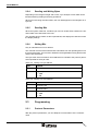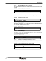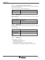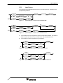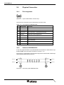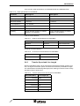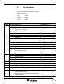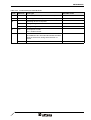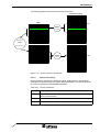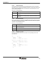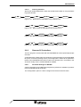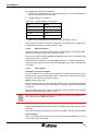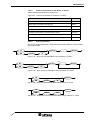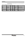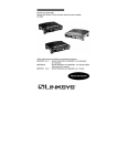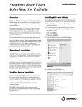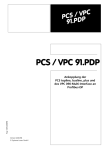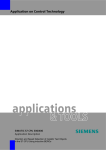
1
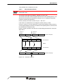
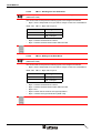
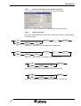
User Manual
Connection to PROFIBUS-DP
Part Number:
80 860.655
Version:
2
Date:
22.11.2005
Valid for:
TSwin .net 4.0x
TSwin .net 4.1x
Version
1
2
Date
25.07.2005
22.11.2005
Modifications
First edition
Validation extended, chapter "Important Notes" added
This manual, including all illustrations contained herein, is copyright protected. Use of this manual by any third
party in departure from the copyright provision is forbidden. No part of this manual may be reproduced, translated or electronically or photographically archived or altered without the express written consent from Sütron
electronic GmbH. Violations shall be cause for damage liability.
Sütron electronic reserves the right to make any changes that contribute to technical improvement.
Overall Table of Contents
Overall Table of Contents
1
2
Important Notes ....................................................................................................... 1-1
1.1
Symbols .................................................................................................... 1-1
1.2
Safety Notes ............................................................................................. 1-1
1.3
Intended Use............................................................................................. 1-1
1.4
Target Group............................................................................................. 1-2
PROFIBUS-DP ........................................................................................................ 2-1
2.1
2.1.1
2.2
Specification for PROFIBUS-DP............................................................... 2-1
Diagnosis ............................................................................................. 2-1
Data Profile ............................................................................................... 2-2
2.2.1
Request telegram ................................................................................ 2-2
2.2.2
Response Telegram ............................................................................ 2-3
2.2.3
User Data............................................................................................. 2-3
2.2.4
Reading and Writing Bytes .................................................................. 2-4
2.2.5
Reading Bits ........................................................................................ 2-4
2.2.6
Writing Bits........................................................................................... 2-4
2.3
Programming ............................................................................................ 2-4
2.3.1
Protocol Parameters ............................................................................ 2-4
2.3.1.1
Maximum Waiting Time For Response.......................................................................2-5
2.3.1.2
Delay until Connection Set-Up....................................................................................2-5
2.3.1.3
Station Number...........................................................................................................2-5
2.3.1.4
Telegram Length.........................................................................................................2-5
2.3.1.5
Floating Point Numbers in the Siemens Format .........................................................2-5
2.3.1.6
Timer and Counter in the Siemens Format.................................................................2-6
2.3.1.7
Byte Order ..................................................................................................................2-6
2.3.1.8
Address Width ............................................................................................................2-6
2.3.2
Polling Area ......................................................................................... 2-6
2.3.3
Input Syntax ......................................................................................... 2-7
2.4
Physical Connection ................................................................................. 2-8
2.4.1
Pin Assignment .................................................................................... 2-8
2.4.2
Cable for PROFIBUS-DP..................................................................... 2-8
2.4.3
Transfer Speed and Line Length ......................................................... 2-9
2.5
Error Messages....................................................................................... 2-10
2.6
Applications............................................................................................. 2-12
2.6.1
Siemens S7 Controllers ..................................................................... 2-12
2.6.1.1
Hardware Configurator .............................................................................................2-12
2.6.1.2
PROFIBUS Function Blocks .....................................................................................2-15
2.6.1.3
Importing the STL Source Files ................................................................................2-15
2.6.1.4
General Functioning .................................................................................................2-16
2.6.1.5
SFC14 Functioning ...................................................................................................2-17
2.6.1.6
FC80 Functioning .....................................................................................................2-18
2.6.1.7
SFC15 Functioning ...................................................................................................2-18
2.6.1.8
Example for an OB1 .................................................................................................2-18
i
Overall Table of Contents
A
ii
2.6.1.9
Defining Variables .................................................................................................... 2-19
2.6.2
Siemens S5 Controllers ..................................................................... 2-19
2.6.2.1
Parameter Settings for IM308B ................................................................................ 2-19
2.6.2.2
Data Consistency ..................................................................................................... 2-20
2.6.2.3
PLC Program............................................................................................................ 2-20
2.6.2.4
FB110 Evaluation Block ........................................................................................... 2-21
2.6.2.5
FB111 - Reading from the Data Block...................................................................... 2-22
2.6.2.6
FB112 - Writing to the Data Block ............................................................................ 2-22
2.6.2.7
Protocol Parameters for the Siemens S5 Series ...................................................... 2-23
2.6.2.8
Defining Variables .................................................................................................... 2-23
2.6.3
Rexroth Controllers ............................................................................ 2-24
2.6.3.1
Configuration in WINSPS ......................................................................................... 2-24
2.6.3.2
Configuration in PROFI ............................................................................................ 2-26
2.6.3.3
Protocol Parameters for BM DP12 ........................................................................... 2-28
2.6.3.4
Protocol Parameters for the Bosch CL Series.......................................................... 2-29
2.6.3.5
Defining Variables .................................................................................................... 2-29
Index ....................................................................................................................... A-1
Important Notes
1
Important Notes
1.1
Symbols
The symbols in this manual are used to draw your attention on notes and dangers.
Danger
This symbol is used to refer to instructions wich, if ignored or not carfully followed
could result in personal injury.
Note
This symbol indicates application tips or supplementary notes.
Reference to source of information
This symbol refers to detailed sources of information on the current topic.
1.2
Safety Notes
–
Read this manual carefully before using the operating device. Keep this manual
in a place where it is always accessible to all users.
–
Proper transportation, handling and storage, placement and installation of this
product are prerequisites for its subsequent flawless and safe operation.
–
This user manual contains the most important information for the safe operation
of the device.
–
The user manual, in particular the safety notes, must be observed by all personnel working with the device.
–
Observe the accident prevention rules and regulations that apply to the operating
site.
–
Installation and operation must only be carried out by qualified and trained personnel.
1.3
Intended Use
–
The device is designed for use in the industry.
–
The device is state-of-the art and has been built to the latest standard safety requirements. However, dangerous situations or damage to the machine itself or
other property can arise from the use of this device.
–
The device fulfills the requirements of the EMC directives and harmonized European standards. Any modifications to the system can influence the EMC behavior.
1-1
Important Notes
1.4
Target Group
All configuration and programming work in connection with the automation system
must be performed by trained personnel only (e.g. qualified electricians, electrical engineers).
The configuration and programming personnel must be familiar with the safety concepts of automation technology.
1-2
PROFIBUS-DP
2
PROFIBUS-DP
Profibus DP provides a manufacturer- and controller-independent data transmission
protocol. The Profibus DP is a speed-optimized Profibus variant that is specially tailored to communication between programmable controllers and decentralized peripheral devices.
Profibus DP is implemented in the operating device and meets the requirements of
parts 1 and 3 of the German standard DIN 19245. It also corresponds to the European field bus standard EN 50170.
As the operating device fulfills standardization requirements, it can be successfully
integrated as a slave into the Profibus DP.
All operating devices can be linked using an integrated Profibus DP additional module. You can also link several operating devices to one master controller.
The entire PROFIBUS DP protocol is handled by the protocol chip SPC3. Transfer
speeds of up to 12 MBaud are possible.
The operating device is used in the bus as a decentralized module that occupies up
to 256 inputs and outputs. The size can be programmed from between 8- and 32byte IN data, and between 8- and 32-byte OUT data. Data transfer is carried out via
the peripheral area.
The input/output image is exchanged cyclically between the master and operating
device via the bus. In this context, the operating device uses the cyclical input/output
image for data exchange between the master and the slave. The data content to be
interpreted is defined for both partners in a data profile.
All services required for running the operating device originate in the operating device. The operating device has client functions.
The controller reacts to the requests of the operating device. It has server functions.
The master module must interpret the incoming data according to the profile and also
respond according to the profile. This is carried out using a function block in the controller that is able to interpret the requests in the IN data, and write a response to the
OUT data.
2.1
Specification for PROFIBUS-DP
The specification of the operating device in PROFIBUS DP is defined using the device data base (GSD) file SE03081A.GSD.
2.1.1
Diagnosis
The operating device implements the station-related diagnosis.
5-byte user diagnosis data is transferred
–
1st byte = error number (1 = communication error in the operating device)
–
2nd and 3rd byte communication error code
–
4th and 5th byte communication error subcode
The communication-error code and subcode are the values that are also displayed
on the operating device.
2-1
PROFIBUS-DP
2.2
Data Profile
To allow direct data access to the different data areas in a controller, a data profile
must be agreed between the master and the slave.
The first four bytes of the telegram length set are used as follows:
–
Telegram sequential number and length
–
Definition of the access
–
Definition of the data area
2.2.1
Table 2-1
Request telegram
Request telegram
Byte
Content
1
Number of user data, sequential number of telegram
2
Access
3
Offset (Depends on Byte Order Setting)
4
High (Low)
5
User Data 1st Byte
6
User Data 2nd Byte
n
User Data nth Byte
Low (High)
Byte 1: Number of User Data
Table 2-2
Number of User Data
Bit
Content
0
Number of User Data in Bytes.
Specifies the number of bytes for the user data transfer.
1
2
3
4
5
6
7
2-2
Sequential Number of the Telegram.
Identification number for each communication process.
(0 = initialization cycle, 1 - 7 = normal sequential number)
PROFIBUS-DP
Byte 2: Access
Table 2-3
Access
Bit
Content
0
Byte Number
For Word Access 0 = First Byte, 1 = Second Byte
1
Reserved
2
3
4
5
6
7
Access:
00 = Bit
01 = Byte
02 = Word
03 = Double word
Data Direction:
0 = Read
1 = Write
Byte 3 and 4: Offset
These bytes contain the address for accessing a data area.
Byte 5 ff: User Data
The user data are located from byte 5 onwards to the end of the telegram.
2.2.2
Table 2-4
Response Telegram
Response telegram
Byte
Content
1
Number of User Data
2
Access
3
Return Code
4
0x00
5
User Data 1st Byte
6
User Data 2nd Byte
n
User Data nth Byte
2.2.3
Error
User Data
The user data are located from byte 5 onwards to end of the telegram.
2-3
PROFIBUS-DP
2.2.4
Reading and Writing Bytes
Depending on the telegram length and access, up to 28 bytes of user data can be
transferred during reading and writing operations.
When bytes are being read and written, the user data appears in the telegram as of
byte five.
2.2.5
Reading Bits
When the system reads bits, it reads a byte, word or double word, based on the address width of the data area to be read.
The operating device masks out the requested bits, and displays the data in line with
the display settings.
2.2.6
Writing Bits
Only an individual bit is set or deleted.
The controller receives a bit mask and link information from the operating device via
the request telegram. The bit is set or deleted in the target address using the bit mask
and the link information.
The byte order of the bit mask for word addresses is oriented to the protocol parameters specified for the byte order.
Table 2-5
Writing to a byte address
Byte
Content
5
Bit Mask
6
Logical Operation
0 = AND
1 = OR
Table 2-6
Writing to a word address
Byte
Content
5
Bit Mask LOW
6
Bit Mask HIGH
7
Logical Operation
0 = AND
1 = OR
2.3
Programming
2.3.1
Protocol Parameters
With the protocol parameters, you can adapt the communication of the controller
used.
2-4
PROFIBUS-DP
2.3.1.1
Maximum Waiting Time For Response
This parameter specifies how long the operating device waits for a response from the
controller.
Table 2-7
Maximum waiting time for response
Configurable Values
Default Value
1 ms to 65535 ms
1000 ms
2.3.1.2
Delay until Connection Set-Up
This parameter specifies the waiting time after which the operating device starts the
communication.
Table 2-8
Delay until connection set-up
Configurable Values
Default Value
1000 ms to 65535 ms
5000 ms
2.3.1.3
Station Number
Specifies the station number of the operating device within the PROFIBUS-DP structure. The station numbers 0 to 2 are reserved.
Table 2-9
Station number
Configurable Values
Default Value
3 to 124
3
2.3.1.4
Telegram Length
The telegram length is set to the PROFIBUS configuration. Specigy the same value
in the PROFIBUS programming software.
Table 2-10
Telegram length
Configurable Values
Default Value
8 Byte to 32 Byte
20 Byte
2.3.1.5
Floating Point Numbers in the Siemens Format
This parameter specifies whether floating point numbers are exchanged in the Siemens-specific format or IEEE format.
Table 2-11
Floating point numbers in the Siemens format
Configurable Values
Default Value
OFF
X
ON
2-5
PROFIBUS-DP
2.3.1.6
Timer and Counter in the Siemens Format
This parameter specifies wether timer and counter are exchanged in the Siemensspecific format or IEEE format.
Table 2-12
Timer and counter in the Siemens format
Configurable Values
Default Value
OFF
X
ON
2.3.1.7
Byte Order
Specify the byte order for word and double-word addresses. (Siemens = High-Low,
Bosch = Low-High)
Table 2-13
Byte order
Configurable Values
Default Value
Low-High
X
High-Low
2.3.1.8
Address Width
Specify the address width you want the operating device to use when accessing controller addresses.
Table 2-14
Adress width
Configurable Values
Default Value
1 = Byte Address
2 = Word Address
X
4 = Doppel-Word Address
2.3.2
Polling Area
Limits applying to the poll area:
2-6
–
The variable must be word-oriented.
–
The area must be contiguous.
–
The controller must be able to access this area in bit-mode.
–
The operating device must be able to access this area in word-mode.
PROFIBUS-DP
2.3.3
Input Syntax
The following figure illustrates the structure of the input syntax for variables in the
programming software.
B
S7
Number
DB
Number
B
DB
Number
DBX
Figure 2-1
.
Number
Syntax diagram for bit access, PROFIBUS-DP.
(1)
BY
S7
Number
DB
Number
BY
DB
Number
DBB
Figure 2-2
.
Number
(2)
Number
Syntax diagram for byte access, PROFIBUS-DP.
1
The number in front of the point is a word or double-word address. The number
after the point specifies the byte number within the word/double word.
2
The number in front of the point is a byte address.
W
S7
Figure 2-3
Number
DB
Number
W
DB
Number
DBW
Syntax diagram for word access, PROFIBUS-DP.
DW
S7
Figure 2-4
Number
DB
Number
DW
DB
Number
DBD
Syntax diagram for double-word access, PROFIBUS-DP
2-7
PROFIBUS-DP
2.4
Physical Connection
2.4.1
Pin Assignment
Figure 2-5
9 pin D-SUB female connector strip
Connector in the terminal: 9 pin D-SUB female connector strip.
Table 2-15
Pin assignment PROFIBUS DP
Pin
Designation
Function
1
nc
Not Connected
2
nc
Not Connected
3
RxD/TxD-P
Received Data / Transmitted Data Plus
4
CNTR-P
Repeater Control Signal Plus
5
DGND
Data Transmission Potential
6
VP
Supply Voltage of Terminators Plus
7
nc
Not Connected
8
RxD/TxD-N
Received Data / Transmitted Data Minus
9
CNTR-N
Repeater Control Signal Minus
2.4.2
Cable for PROFIBUS-DP
In the wiring depicted below, the potential difference between the data reference potentials DGND of all connections are NOT to exceed +/- 7 V.
Ensure that no compensating current flow through the bus cable shield. Install a separate equipotential bonding conductor.
RxD/TxD-P
RxD/TxD-N
3
WH
WH
3
8
BN
BN
8
Figure 2-6
2-8
Connecting cable PROFIBUS-DP
RxD/TxD-P
RxD/TxD-N
PROFIBUS-DP
There are two cable specifications for PROFIBUS-FMS and PROFIBUS-DP:
Table 2-16
Cable specification for PROFIBUS
Parameter
Cable type A
Cable type B
Wave Impedance
135 to 165 Ohm (for f = 3 to 20 MHz)
100 to 135 Ohm (for f > 100 MHz
Cable capacity
< 30 pF/m
< 60 pF/m
Wire cross-section
> 0.34 mm2
> 0.22 mm2
Loop Impedance
< 110 Ohm/km
---
Signal attentuation
max. 9 dB
max. 9 dB
Cable type
twisted-pair 1 x 2 / 2 x 2 / 1 x 4 wires
twisted-pair1x 2 / 2 x 2 / 1 x 4 wires
Shielding
Copper braided shielding or braided
shielding + foil shielding
Copper braided shielding or braided
shielding + foil shielding
Cable recommendations:
Table 2-17
Cable recommendations for PROFIBUS
Field of Application
Manufacturer
Order Number
Standard
Siemens
6XV1 830-0AH10
Trailing cable
Siemens
6XV1 830-3BH10
Connector recommendations:
Table 2-18
Connector recommendations for PROFIBUS
Manufacturer
Order Number
Siemens
6ES79 0BA20-0XA0
2.4.3
Transfer Speed and Line Length
With the PROFIBUS, data can be transferred using different transfer speeds. However, the higher the transfer speed, the shorter the maximum permitted line length.
The values listed in the following table apply to the cable type A which is more closely
specified in DIN E 19245 part 3.
Table 2-19
Transfer speed versus line length for PROFIBUS
Baud Rate (Bit/s)
Line Length (m)
187 500
1000
500 000
400
1 500 000
200
3 000 000
100
6 000 000
100
12 000 000
100
2-9
PROFIBUS-DP
2.5
Error Messages
Error messages are displayed on the operating device along with a code and subcode. Error messages are composed as follows:
Communication Error
Table 2-20
Code
Code
XXXXX
Subcode
XXXXX
Retries
XXXXX
Fehlermeldungen PROFIBUS-DP
Subcode
Error Type
1
Slave is currently not ready
2
Packets out of sequence
3
Protocol framing error
4
Timeout
5
CRC error
6
Parity error
7
Send process aborted
8
Receive process aborted
9
Buffer too small for cyclic data
10
No cyclic data defined
12
Cyclic data already defined
15
The selected protocol is not supported
16
Receive buffer overrun
40
Undefined system variable
1
50
Error initializing the SPC3
1
Buffer too large
2
No initialization of SPC3
4
No memory for telegram buffer
60
No configuration from master
61
Wrong input length
62
Wrong output length
63
Error in configuration data, reparameterization required
64
Protocol chip requires configuration update, reparameterization required.
65
No communication via protocol chip, reparameterization required.
2-10
Possible Cause
PROFIBUS-DP
Table 2-20
Code
Fehlermeldungen PROFIBUS-DP
Subcode
Error Type
66
Protocol chip reset, reparameterization required.
67
Watchdog time error, reparameterization required.
70
Operating device is not polled
71
0
Distinguishing feature for manufacturer
1
Distinguishing feature for manufacturer
xxx
No response to order.
xxx = variable number
100
Possible Cause
Base no. for error from PLC function block. PLC error is added to 100. The subcode indicates the offset
value for the access, during which the error occurred.
i.e. 102
Access to DB via FB111 / FB112 DB does not exist
2-11
PROFIBUS-DP
2.6
Applications
The controller program, which is usually a function block, must handle the requests
of the operating device in line with the data profile.
The details depend on the controller. The following sections explain the controllerspecific applications that have been developed to date.
The device data base (GSD) file SE03081A.GSD can be used to set the parameters
of the operating devices in the PLC software. This file is available in a subdirectory
of the programming software and in our Internet download area.
2.6.1
Siemens S7 Controllers
The following dialog boxes and the way in which they are used may vary in the different versions of Step7 software. The procedure for defining a PROFIBUS DP slave
is the same in all versions, but is not described in this documentation. The dialog
boxes depicted here were developed for version 5.1 of an S7-300 controller.
2.6.1.1
Hardware Configurator
To integrate the operating device into the PROFIBUS DP structure, you must firstly
introduce the operating devices into the system.
Proceed as follows:
1. Start the Hardware Configurator in S7.
2. From the Options menu, select the menu item Install New GSD.
The following dialog opens.
Figure 2-7
Dialog 'Install New GSD'
3. From your main TSwin directory navigate to the subdirectory ..\FBs\Profibus\TYP_GSD.
4. Select the file SE03081A.GSD.
5. Click 'Open' to confirm your selection.
2-12
PROFIBUS-DP
In the hardware catalog, the operating device is then listed as follows:
Figure 2-8
Hardware catalog
To integrate the operating device into PROFIBUS-DP, do the following:
1. Click on the TesiMod BT item and, keeping the mouse button pressed, drag and
drop this item to the icon for the PROFIBUS DP master system.
The pointer becomes a cross.
2. Release the mouse button.
The following dialog opens.
Figure 2-9
Dialog 'Properties - PROFIBUS interface TesiMod BT
3. Specify an address for the operating device (3).
4. Click OK to confirm your actions.
2-13
PROFIBUS-DP
The hardware configurator now looks as shown below:
Figure 2-10
Hardware configuration
You must also set the parameters for the operating device as a DP slave. Proceed
as follows:
1. Click on the element Universal Module and, keeping the mouse button pressed,
drag and drop the element to the top line in the table.
The pointer becomes a cross.
Release the mouse button.
The item is entered into the table.
2. Select the menu item Object Properties from the Edit menu.
3. Specify the properties as shown below.
2-14
PROFIBUS-DP
Figure 2-11
Dialog Properties - DP Slave
You can select your entries for address, length, and unit as needed. The settings depicted below generate the value 191 in the ID byte.
2.6.1.2
PROFIBUS Function Blocks
You need Sütron function blocks to interpret and evaluate the data. The cyclical call
sequence of the function blocks must be adhered to.
2.6.1.3
Importing the STL Source Files
Import the STL (AWL) files supplied with the product in the Simatic Manager.
Proceed as follows:
1. Select the Sources folder in the Simatic Manager.
2. From the Insert menu, select the menu item External Source.
The following dialog opens.
Figure 2-12
Dialog Insert External Source
3. From your main TSwin directory navigate to the subdirectory ..\FBs\PROFIBUS\SIEMENS\S7\300_400.
4. Select the STL file FC70.AWL and select Open to confirm.
The name is now entered in the Sources folder in the S7 Manager.
5. Open the STL file, and compile and convert it into the S7 function block format.
2-15
PROFIBUS-DP
2.6.1.4
General Functioning
The peripheral data is processed using the functions SFC14 and SFC15 of the S7
CPU. SFC14 reads the peripheral data, and SFC15 writes the data to the periphery.
FC80 takes on the data provided by SFC14 and calls the read or write function, and
transfers the data read to SFC15. The local data stack of FC80, FC81, and FC82 is
used to process protocol data.
SFC14, FC70 (FC80) and SFC15 must be called cyclically in the program.
The following cyclical call sequence must be adhered to:
1
SFC14
2
FC70 (FC80)
3
SFC15
The functions FC80, FC81, and FC82 use the register-indirect, cross-area address
form. If interrupt-controlled program calls are permitted in the program cycle, the contents of the address registers 1 and 2, and possibly also the local data stack, may
need to be saved, in addition to the contents of both accumulators.
The operating device can access the controller data on a bit, byte, word, or doubleword basis. Bit access is possible to a byte address. As the protocol profile itself does
not transfer data type code, these are transferred using the variable numbers. Each
variable is uniquely identified using a variable number. This number is defined during
programming.
2-16
PROFIBUS-DP
The following graphic shows how the function blocks work.
Peripherie-Eingänge
DB80
W#16#50
P#DB80.DBX 4.0 BYTE 16
PEB80
SFC14
[LADDR]
[RECORD_IN]
Peripherie-Ausgänge
DB81
FC80
[RECORD_OUT]
P#DB81.DBX 32.0 BYTE 16
SFC15
W#16#50
PAB80
[LADDR]
Figure 2-13
2.6.1.5
How the function blocks work
SFC14 Functioning
SFC14 reads the data from the peripheral inputs, starting with the start address
(LADDR) and copies the data to a specific target (RECORD). The amount of data to
be copied is contained in the RECORD parameter.
Table 2-21
SFC14 parameters
Name
Meaning
LADDR
Specifies the start address for the peripheral inputs of the operating
device (hexadecimal)
RET_VAL
Return value of the SFC14 in case of an error
RECORD
Copy target for the read peripheral data
2-17
PROFIBUS-DP
2.6.1.6
FC80 Functioning
FC80 reads the data transferred from the operating device from the copy target
RECORD of SFC14. Based on the telegram transferred, it carries out a read or write
access. It then transfers the data to be transferred to the operating device to the
source data area of SFC15.
Table 2-22
FC80 parameters
Name
Meaning
Record_In
Start address for the input data (= parameter RECORD of the
SFC14)
Record_Out
Start address for the output data (= parameter RECORD of the
SFC15)
2.6.1.7
SFC15 Functioning
SFC15 reads the data from the source RECORD and copies the data to the peripheral outputs, starting with the address LADDR. The amount of data to be copied is
contained in the RECORD parameter.
Table 2-23
SFC15 parameters
Name
Meaning
LADDR
Specifies the start address for the peripheral outputs of the operating
device (hexadecimal)
RET_VAL
Return value of the SFC15 in case of an error
RECORD
Copy source for the data to be transferred
2.6.1.8
Example for an OB1
The following example refers to the connection of one operating device to the
PROFIBUS-DP.
...
//
Call
SFC
[LADDR]
:=
[RET_VAL]
:=
[RECORD]
:=
//
Call
FC
[RECORD_IN] :=
[RECORD_OUT] :=
//
Call
SFC
[LADDR]
:=
[RECORD]
:=
[RET_VAL]
:=
...
BE
2-18
14
W#16#50
MW62
P#DB80.DBX 4.0 BYTE 16
80
P#DB80.DBX 4.0 BYTE 16
P#DB81.DBX 32.0 BYTE 16
15
W#16#50
P#DB81.DBX 32.0 BYTE 16
MW64
PROFIBUS-DP
2.6.1.9
Defining Variables
Specify the variable addresses in either the hexadecimal notation or using the following syntax formats:
DB
DBX
Number
Figure 2-14
2.6.2
DBB
Number
Zahl
Number
DBW
Number
Word access for PROFIBUS using a Siemens S7
DB
Figure 2-17
Number
Zahl
Byte access for PROFIBUS using a Siemens S7
DB
Figure 2-16
Number
Bit access for PROFIBUS using a Siemens S7
DB
Figure 2-15
.
Number
Number
DBD
Number
Double-word access for PROFIBUS using a Siemens S7
Siemens S5 Controllers
The PLC program communicates with the PROFIBUS DP via the input/output peripheral area.
A separate IN/OUT data channel is assigned to each participant on the PROFIBUS
DP (each connected operating device). The assignment is made via the parameterization of the PROFIBUS-DP master module in the Siemens PLC. Controllers in the
S5 series usually use the module IM308B or IM308C.
2.6.2.1
Parameter Settings for IM308B
A device type file for the COMET200 programming software is available to parameterize the IM308B.(BT081ATD.200)
The 'Configuration' option is used to configure the terminal of the DP slave.
2-19
PROFIBUS-DP
The following parameters are specified:
1. Position of the operating device in the peripheral area, i.e. the I/O addresses on
which the operating device is located.
2. The DP identifier via module 0
Table 2-24
The DP identifier via module 0
Item
Value
I/O
X
Length
4, 6, 8, 14, 16
Format
Word
Consistency
0 Word Consistency
3. Data for the parameterization telegram are not applicable, no entry.
Using a program module, this module configuration is loaded into the module with
the parameter settings of the entire master module.
2.6.2.2
Data Consistency
A data consistency over the entire length set must be applied for exchanging data
between the operating device and the master module.
However, the master modules IM308B and IM308C only ensure a consistency with
a data width of up to one word.
Program-specific measures in the PROFIBUS DP driver of TesiMod operating devices ensure consistency up to the maximum data length which can be specified, that
is 32 bytes.
2.6.2.3
PLC Program
Evaluation of the Control Bytes:
The PLC program must cyclically poll the peripheral area that is assigned to the operating device. Using the sequential number, it must check whether a new request
has been received from the operating device.
FB110 carries out this task.
FB110 is parameterized with the peripheral address of the corresponding operating
device, to ensure that only one function block is required to connect several operating devices.
FB110 must also copy bytes 1 and 2, unchanged, from the request to the response
telegram, and 0x00 must be written to byte 3.
Take note of the consistency settings when reading and writing to the peripheral
area. (Also see the COMET200 manual.)
Processing user data:
Separate read and write function blocks that are called by FB110 are used to process
user data.
The read and write function blocks process the user data in line with the data profile.
Error Handling:
Errors can be entered in the return code, byte 4 of the response telegram. If no error
occurs, byte 4 must be deleted.
2-20
PROFIBUS-DP
One possible error is: DB does not exist.
2.6.2.4
FB110 Evaluation Block
The description for this function block is for version 2.0 and higher
(PROF02ST.S5D).
The function block (FB) uses MW246 - MW254 as scratch flag.
The function block also needs a separate data word for each operating device. The
data word is transferred as a parameter during the call. The telegram sequential
number is saved in this data word.
FB110 cyclically checks the contents of byte 1 - bits 5 to 7.
If the value 0 is contained here, the telegram number memory is reset.
If in byte 1, bits 5 to 7 are not equal to the content of the telegram number memory,
a new request telegram has been received from the operating device, and this must
be evaluated and a response sent.
FB110 is called cyclically in OB1 with the corresponding parameters for each operating device.
Terminal 1
Terminal 2
PW128
PW136
Byte 1 bis 4
P-Bereich Eingänge
MB250
MB251
MB252
MB253
0x00
MB250
MB251
MB252
Byte 1 bis 4
PW128
Figure 2-18
Schmiermerker
FB110
MB253
Schmiermerker
P-Bereich Ausgänge
PW136
Structure of FB110
2-21
PROFIBUS-DP
2.6.2.5
FB111 - Reading from the Data Block
The description for this function block is for version 2.0 and higher
(PROF02ST.S5D).
The function block interprets the following bytes in the telegram as follows:
–
Byte 2, bit 0 is interpreted as a byte code for a byte access to a word address.
Table 2-25
FB111 - Byte code in byte 2
Value
Meaning
0
DL - High Byte
1
DR - Low Byte
–
Byte 3 contains the data block number.
–
Byte 4 contains the data word number within the DB.
Siehe Kapitel „Data Profile“ auf Seite 2-2.
2.6.2.6
FB112 - Writing to the Data Block
The description for this function block is for version 2.0 and higher
(PROF02ST.S5D).
The function block interprets the following bytes in the telegram as follows:
–
Byte 2, bit 0 is interpreted as a byte code for a byte access to a word address.
Table 2-26
–
FB111 - Byte code in byte 2
Value
Meaning
0
DL - High Byte
1
DR - Low Byte
Byte 3 contains the data block number.
–
Byte 4 contains the data word number within the DB.
–
Byte 5 and
–
Byte 6 contain the bit mask for the logical operation.
–
Byte 7 contains the logical instruction (AND / OR).
Siehe Kapitel „Data Profile“ auf Seite 2-2.
2-22
PROFIBUS-DP
2.6.2.7
Protocol Parameters for the Siemens S5 Series
For the protocol, specify the parameters shown in the figure below.
Figure 2-19
2.6.2.8
Protocol parameters for PROFIBUS using a Siemens S5
Defining Variables
Specify the variable addresses in either the hexadecimal notation or using the following syntax formats:
B
DB
.
Number
Number
B
Number
Figure 2-20
Bit access for PROFIBUS using a Siemens S5
(1)
BY
DB
.
Number
(2)
BY
Number
Figure 2-21
Byte access for PROFIBUS using a Siemens S5
W
Number
DB
Figure 2-22
Number
W
Word access for PROFIBUS using a Siemens S5
DW
DB
Figure 2-23
Number
Number
Number
DW
Double-word access for PROFIBUS using a Siemens S5
2-23
PROFIBUS-DP
2.6.3
Rexroth Controllers
The PLC program communicates with the PROFIBUS DP via the input/output peripheral area.
Each participant, including each operating device in the PROFIBUS DP, is assigned
an IN and OUT data channel.
The channel is assigned using the parameterization of the Bosch controller’s PROFIBUS DP master module. The module MP-DP12 is used in Bosch controllers.
2.6.3.1
Configuration in WINSPS
Evaluation of the control bytes in the PLC Program:
The PLC program must cyclically poll the peripheral area that is assigned to the operating device. Using the sequential number, it must check whether a new request
has been received from the operating device. In addition, bytes 1 and 2 must be copied, unchanged, from the request telegram to the response telegram, and 0x00 must
be written to byte 3.
You require the following modules for this task. They are contained in a subfolder of
the programming software’s installation folder.
Table 2-27
Function blocks for the programming software WINSPS
Controller
Function Block
CL200
..\FBs\Profibus\BOSCH\WINSPS\CL200\BT_PB2.pxl
CL300
..\FBs\Profibus\BOSCH\WINSPS\CL345\BT_PB345.pxl
CL400
..\FBs\Profibus\BOSCH\WINSPS\CL345\BT_PB345.pxl
CL500
..\FBs\Profibus\BOSCH\WINSPS\CL345\BT_PB345.pxl
SoftSPS
..\FBs\Profibus\BOSCH\WINSPS\PLC\BT_PBPLC.pxl
Error Handling in the PLC Program:
Errors can be entered in the return code, byte 4 of the response telegram. If no error
occurs, byte 4 must be deleted. Possible errors are:
–
DB does not exist.
Function Blocks Supplied:
You must configure the operating device as the slave using 'n Byte kons. Daten E/A'
(n byte cons. data I/O) in the DP master module.
If you are using interrupts, you must save the scratch flags and the four registers
used in the interrupt OB.
Inserting the Library Files in WINSPS
1. Start WinSPS.
2. Copy the corresponding pxl file to the ZSO directory of the PLC project.
You can only copy the file to the appropriate project directory as modules of the incorrect controller type are not recognized!
3. Assign the library in the toolbar.
Example:
FC10, R BT_PB345
4. Open the editor in the PLC software.
2-24
PROFIBUS-DP
Example:
OB1
Select the PROFIBUS block from the 'Edit/Parameter list' menu.
Parameterizing the call-up function:
Example:
For two operating devices:
...
;DEF für Gerät 1
DEF
DEF
DEF
DEF
DEF
;DEF für Gerät 2
DEF
DEF
DEF
DEF
DEF
;Aufruf Gerät 1
BA
P0
P1
P2
P3
P4
;Aufruf Gerät 1
BA
P0
P1
P2
P3
P4
...
10,-EZ_Basisn
10,-AZ_Basisn
DB50,-DBNR
0,-WDNR
20,-TLNG
10,-EZ_Basisn2
10,-AZ_Basisn2
DB50,-DBNR2
0,-WDNR2
20,-TLNG2
W
W
W
W
W
W
W
W
-BT_345,5FC10
-EZ_Basisn
-AZ_Basisn
-DBNR
-WDNR
-TLNG
-BT_345,5FC10
-EZ_Basisn2
-AZ_Basisn2
-DBNR2
-WDNR2
-TLNG2
Function Block BT_PB345:
The function block BT_DP345 is used to decode the transfer protocol of the operating devices. It ensures consistent data transfer.
When you program the controller, note that a total of 64 bytes as of the address
DB[P2] W[P3] are reserved for processing the protocol. Other program components
cannot use this area!
The function block BT_PB345 uses the following parameters:
Table 2-28
Parameters for function block BT_PB345
Parameter
Function
P0
EZ Base Address
P1
AZ Base Address
P2
Data block for storing the EZ/AZ data
P3
Base Address in Data Block [P2]
P4
Telegram Length
corresponds to the number of EZ/AZ data of the slave configuration (8, 12, 16, 20, 28, or 32 bytes)
2-25
PROFIBUS-DP
2.6.3.2
Configuration in PROFI
Table 2-29
Function blocks for the programming software PROFI
Controller
Function Block
CL200
..\FBs\Profibus\BOSCH\PROFI\CL200\BT_MAIN.PBO
..\FBs\Profibus\BOSCH\PROFI\CL200\BT_READ.PBO
..\FBs\Profibus\BOSCH\PROFI\CL200\BT_WRITE.PBO
..\FBs\Profibus\BOSCH\PROFI\CL200\OB1.PBO
CL300
..\FBs\Profibus\BOSCH\PROFI\CL350400/BT_MAIN.PCO
..\FBs\Profibus\BOSCH\PROFI\CL350400\BT_READ.PCO
..\FBs\Profibus\BOSCH\PROFI\CL350400\BT_WRITE.PCO
..\FBs\Profibus\BOSCH\PROFI\CL350400\OB1.PCO
CL400
..\FBs\Profibus\BOSCH\PROFI\CL350400/BT_MAIN.PCO
..\FBs\Profibus\BOSCH\PROFI\CL350400\BT_READ.PCO
..\FBs\Profibus\BOSCH\PROFI\CL350400\BT_WRITE.PCO
..\FBs\Profibus\BOSCH\PROFI\CL350400\OB1.PCO
CL500
..\FBs\Profibus\BOSCH\PROFI\CL500/BT_MAIN.P5O
..\FBs\Profibus\BOSCH\PROFI\CL350400\BT_READ.P5O
..\FBs\Profibus\BOSCH\PROFI\CL350400\BT_WRITE.P5O
..\FBs\Profibus\BOSCH\PROFI\CL350400\OB1.P5O
Function Block BT_MAIN
Structure of the block:
Terminal 1
Terminal 2
EZ10
EZ20
Byte 1 to 4
MB250
EZ-Area Inputs
MB251
MB252
MB253
0x00
MB250
MB251
MB252
Byte 1 to 4
2-26
Scatch Flags
BT_MAIN
MB253
Scatch Flags
AZ-Area Outputs
AZ10
AZ20
Figure 2-24
Structure of the BT_MAIN
PROFIBUS-DP
Function Block BT_MAIN Call-Up
Example:
Call-up in OB1
;OB1 Organisationsbaustein
;*****************************************
;Profibus-DP-Koomunikation mit Bediengerät
;Beispiel zur Einbindung im OB1
;*****************************************
;Befehle notwendig für Profibus
L W
EZ2,A ;Adresse muss mit Koppeladresse übereinstimmen
T W
A,AZ2 ;nur für CL400
;Einmal pro Bediengerät aufrufen
BA -BT_MAIN,4
;Aufruf für das erste Bediengerät
;
+---+
P0 W
K10 ; < ! Adresse des Eingangsbereichs
P1 W
K10 ; < ! Adresse des Ausgangsbereichs
P2 W
DB0 ; < ! Nummer des Datenbausteins
P3 W
D0 ; < ! Datenwortnummer
;
+---+
PE
Function Block BT_READ
The function block BT_READ interprets the subsequent bytes in the telegram as follows:
–
Byte 2, bit 0 is interpreted as a byte code for a byte access to a word address.
Table 2-30
Byte code in byte 2
Value
Meaning
0
Odd Address - Low Byte
1
Even Address - High Byte
–
Byte 3 contains the data block number.
–
Byte 4 contains the data word number within the DB.
The program module doubles the data word number for the even-numbered byte
number in the DB.
Function Block BT_WRITE
The function block BT_WRITE interprets the subsequent bytes in the telegram as follows:
–
Byte 2, bit 0 is interpreted as a byte code for a byte access to a word address.
Table 2-31
Byte code in byte 2
Value
Meaning
0
Odd Address - Low Byte
1
Even Address - High Byte
–
Byte 3 contains the data block number within the DB.
–
Byte 4 contains the data word number within the DB (0 to 255).
–
Byte 5 and
–
Byte 6 contain the bit mask for the logical operation.
–
Byte 7 contains the logical instruction (AND / OR).
2-27
PROFIBUS-DP
Parameterization of the BM-DP12 Module
Set the parameters for the module using the Bosch DP software.
The device data base (GSD) file SE03081A.GSD which is supplied is directly read in
by the DP software. This means that the data required to set the parameters of the
operating devices are automatically available.
Select the operating device with the required data width.
The function block copies bytes 1 and 2, unchanged, from the request telegram to
the response telegram, and writes 0x00 to byte 3.
The function block uses MW248 to MW254 as scratch flags.
For each operating device, the program block also requires any data word of a data
block. The data word is transferred as a parameter during the call. The telegram sequential number is saved in this data word.
The function block cyclically checks the content of byte 1 – bits 5 to 7.
If the value 0 is contained here, the telegram number memory is reset.
If in byte 1, bits 5 to 7 are not equal to the content of the telegram number memory,
a new request telegram has been received from the operating device, and this must
be evaluated and a response sent.
The function block is called cyclically in OB1 with the corresponding parameters for
each operating device.
2.6.3.3
Protocol Parameters for BM DP12
Set the following parameters for the protocol:
Table 2-32
Protocol parameters for the Bosch CL series
Parameter
Value
Maximum Waiting Time for Response [ms]
1000
Delay Until Connection Set-Up [ms]
5000
Station Number
3
Telegram Length
16
Floating Point Number in the Siemens Format
Inactive
Byte Order is High-Low
Inactive
Address Width
2
Set the parameters using the Bosch DP software. The supplied device data base file
SE03081A.GSD is directly imported by the DP software. Therefore, the data required
to set the parameters of the operating devices are available in the DP software. You
can specify 8, 12, or 16 bytes for the telegram length.
2-28
PROFIBUS-DP
2.6.3.4
Protocol Parameters for the Bosch CL Series
Set the following parameters for the protocol:
Table 2-33
Protocol parameters for the Bosch CL series
Parameter
Value
Maximum Waiting Time for Response [ms]
1000
Delay Until Connection Set-Up [ms]
5000
Station Number
3
Telegram Length
20
Floating Point Number in the Siemens Format
Inactive
Byte Order is High-Low
Inactive
Address Width
2
2.6.3.5
Defining Variables
Specify the variable addresses in either the hexadecimal notation or using the following syntax formats:
B
DB
.
Number
Number
B
Number
Figure 2-25
Bit access for PROFIBUS using the Bosch CL series
(1)
BY
DB
.
Number
(2)
BY
Number
Figure 2-26
Byte access for PROFIBUS using the Bosch CL series
W
Number
DB
Figure 2-27
Number
W
Word access for PROFIBUS with the Bosch CL series
DW
DB
Figure 2-28
Number
Number
Number
DW
Double-word access for PROFIBUS using the Bosch CL series
2-29
PROFIBUS-DP
In the variable list of the programming software, you can also enter the addresses in
hexadecimal notation:
Table 2-34
Hexadecimal notation for addresses
Variable Name
Address (hex)
Var1
PLC Access
PLC Address
DW H124B
Double Word
DB18 D150 to D153
Var2
W H124B
Word
DB18 D150 and D151
Var3
BY H124B
Byte
DB18 D151
Var4
BY H124B
1
1
Bit
DB18 D150 Bit 5
Var5
B H124B
13
13
Bit
DB18 D151 Bit 5
2-30
LowBit
HighBit
Index
A Index
C
Cable
PROFIBUS-DP ......................................... 2-8
I
Important notes ................................................. 1-1
Intended use ..................................................... 1-1
P
PROFIBUS-DP ................................................. 2-1
Data profile ............................................... 2-2
Request telegram ..................................... 2-2
Response telegram................................... 2-3
Protocol parameters
PROFIBUS-DP ......................................... 2-4
S
Safety notes ...................................................... 1-1
Symbols ............................................................ 1-1
T
Target group ..................................................... 1-2
A-1
Index
A-2
Sütron electronic GmbH
Kurze Straße 29
D-70794 Filderstadt
Phone: 0049 711 / 77098-0
Fax:
0049 711 / 77098-60
E-mail: [email protected]
Internet: www.suetron.com