1
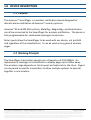
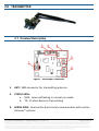
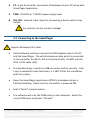
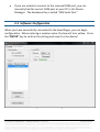
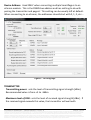
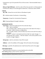
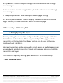
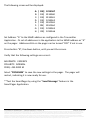
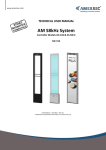
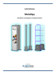
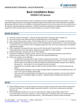
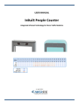
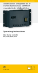
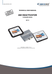
www.amersec.com TECHNICAL USER MANUAL SmartPager digital security wireless system v1.0 TECHNICAL MANUAL – SMARTPAGER – REV 1.0 Confidential and proprietary information, for internal use only Contents 1.0 DEVICE DESCRIPTION............................................................................................................. 3 1.1 Purpose ................................................................................................................................ 3 1.2 Working Principle ................................................................................................................. 3 2.0 TRANSMITTER........................................................................................................................ 4 2.1 Terminal Description ............................................................................................................ 4 2.2 Connecting to the SmartPager.............................................................................................. 5 2.3 Software Configuration ........................................................................................................ 6 3.0 SMARTPAGER ........................................................................................................................ 9 3.1 Description ........................................................................................................................... 9 3.2 Configuring the Pager ......................................................................................................... 10 4.0 DECLARATION...................................................................................................................... 12 5.0 NOTES...................................................................................... Error! Bookmark not defined. TECHNICAL MANUAL – SMARTPAGER – REV 1.0 PAGE 2 of 12 This document was created to provide the intended recipient documentation for technician purposes only. Any other usage of this document is an illegal and unlawful act. This document is a confidential and proprietary document of American Security spol. s r.o. and consists of information that is protected by copyrights or intellectual property protection of other subjects. All other information, which is not generally known, is intellectual property of American Security spol. s r.o. This document including any and all attachments hereto is intended solely to be used by individuals or entities to which it is addressed. If the reader of this document is not the intended recipient, or an employee or agent responsible for delivering this document to its intended recipient, you are herewith notified that any dissemination, distribution, copying or retention of this document or the information contained herein is strictly prohibited. If you have received this document in error, please notify us at [email protected] immediately and permanently delete and/or destroy the original and any copy or printout thereof. 1.0 DEVICE DESCRIPTION 1.1 Purpose The Amersec® SmartPager is a wireless notification device designed for discrete alarm notification of Amersec® security systems. Amersec® RF and AM EAS systems, MetalSpy, MagnetSpy, and deactivators can all be connected to the SmartPager for wireless notification. The device is fully programmable for customized message transmission. Relay inputs allow the SmartPager to be used with any device, not just EAS and regardless of the manufacturer. It can be used as any general wireless pager. 1.2 Working Principle The SmartPager transmitter operates on a frequency of 433.92MHz. An alphanumeric message is transmitted to a display pager up to 100m away. The wireless range depends on store layout and materials in the store. Pagers can be paired to specific transmitters to allow multiple systems to operate together in one location. TECHNICAL MANUAL – SMARTPAGER – REV 1.0 PAGE 3 of 12 This document was created to provide the intended recipient documentation for technician purposes only. Any other usage of this document is an illegal and unlawful act. This document is a confidential and proprietary document of American Security spol. s r.o. and consists of information that is protected by copyrights or intellectual property protection of other subjects. All other information, which is not generally known, is intellectual property of American Security spol. s r.o. This document including any and all attachments hereto is intended solely to be used by individuals or entities to which it is addressed. If the reader of this document is not the intended recipient, or an employee or agent responsible for delivering this document to its intended recipient, you are herewith notified that any dissemination, distribution, copying or retention of this document or the information contained herein is strictly prohibited. If you have received this document in error, please notify us at [email protected] immediately and permanently delete and/or destroy the original and any copy or printout thereof. 2.0 TRANSMITTER 2.1 Terminal Description Figure 1 - SmartPager Transmitter 1. ANT: SMA connector for transmitting antenna 2. STATUS LEDs: a. RUN: slow red flashing in normal run mode b. TX: lit when device is transmitting 3. SERIAL PINS: terminal for direct serial communication with certain Amersec® systems TECHNICAL MANUAL – SMARTPAGER – REV 1.0 PAGE 4 of 12 This document was created to provide the intended recipient documentation for technician purposes only. Any other usage of this document is an illegal and unlawful act. This document is a confidential and proprietary document of American Security spol. s r.o. and consists of information that is protected by copyrights or intellectual property protection of other subjects. All other information, which is not generally known, is intellectual property of American Security spol. s r.o. This document including any and all attachments hereto is intended solely to be used by individuals or entities to which it is addressed. If the reader of this document is not the intended recipient, or an employee or agent responsible for delivering this document to its intended recipient, you are herewith notified that any dissemination, distribution, copying or retention of this document or the information contained herein is strictly prohibited. If you have received this document in error, please notify us at [email protected] immediately and permanently delete and/or destroy the original and any copy or printout thereof. 4. PC: 6-pin terminal for connection of Hardware Key for PC setup with SmartPager Application 5. PWR: 9-24VDC or 7-15VAC power supply input 6. IN1, IN2: external input relays for connecting a device switch relay output Dry contacts, do not connect voltage! 2.2 Connecting to the SmartPager Requires Windows XP or later Install software and then connect the USB Hardware Key to the PC and the SmartPager. The white telephone cable which is connected to the controller has RJ14 + RJ12 connectors (4/6). Do NOT use the RJ12 + RJ12 cable (4/4). The Hardware Key is used as a USB converter, and for security. Only 1 key is needed for each technician, it is NOT left at the installation with the system. Open the SmartPager Application AFTER the hardware driver is finished installing. Make sure the transmitter is powered ON. Select “Serial” communication. The software will scan the COM ports on the computer. Select the correct COM port and press “Connect” TECHNICAL MANUAL – SMARTPAGER – REV 1.0 PAGE 5 of 12 This document was created to provide the intended recipient documentation for technician purposes only. Any other usage of this document is an illegal and unlawful act. This document is a confidential and proprietary document of American Security spol. s r.o. and consists of information that is protected by copyrights or intellectual property protection of other subjects. All other information, which is not generally known, is intellectual property of American Security spol. s r.o. This document including any and all attachments hereto is intended solely to be used by individuals or entities to which it is addressed. If the reader of this document is not the intended recipient, or an employee or agent responsible for delivering this document to its intended recipient, you are herewith notified that any dissemination, distribution, copying or retention of this document or the information contained herein is strictly prohibited. If you have received this document in error, please notify us at [email protected] immediately and permanently delete and/or destroy the original and any copy or printout thereof. If you are unable to connect to the scanned COM port, you can manually find the correct COM port on your PC in the Device Manager. The Hardware Key is called “USB Serial Port.” 2.3 Software Configuration When you have successfully connected to the SmartPager, you can begin configuration. When entering a number value, the box will turn yellow. Press the “ENTER” key to confirm the setting and save it to the device! Figure 2 - Communication Page TECHNICAL MANUAL – SMARTPAGER – REV 1.0 PAGE 6 of 12 This document was created to provide the intended recipient documentation for technician purposes only. Any other usage of this document is an illegal and unlawful act. This document is a confidential and proprietary document of American Security spol. s r.o. and consists of information that is protected by copyrights or intellectual property protection of other subjects. All other information, which is not generally known, is intellectual property of American Security spol. s r.o. This document including any and all attachments hereto is intended solely to be used by individuals or entities to which it is addressed. If the reader of this document is not the intended recipient, or an employee or agent responsible for delivering this document to its intended recipient, you are herewith notified that any dissemination, distribution, copying or retention of this document or the information contained herein is strictly prohibited. If you have received this document in error, please notify us at [email protected] immediately and permanently delete and/or destroy the original and any copy or printout thereof. Device Address: Used ONLY when connecting multiple SmartPagers to an eComm module. This is the RS485 bus address and has nothing to do with pairing the transmitter and pagers! This setting can be usually left at default. When connecting to an eComm, the addresses should start with 0, 1, 2, etc…. Figure 3 - TX Config Page TRANSMITTER Transmitting power: sets the level of transmitting signal strength [dBm]. Recommended value is from +3 to -3dBm Maximum level of RSSI: sets the level of received signal strength [dBm]. If the received signal exceeds this value, the transmitter will wait with TECHNICAL MANUAL – SMARTPAGER – REV 1.0 PAGE 7 of 12 This document was created to provide the intended recipient documentation for technician purposes only. Any other usage of this document is an illegal and unlawful act. This document is a confidential and proprietary document of American Security spol. s r.o. and consists of information that is protected by copyrights or intellectual property protection of other subjects. All other information, which is not generally known, is intellectual property of American Security spol. s r.o. This document including any and all attachments hereto is intended solely to be used by individuals or entities to which it is addressed. If the reader of this document is not the intended recipient, or an employee or agent responsible for delivering this document to its intended recipient, you are herewith notified that any dissemination, distribution, copying or retention of this document or the information contained herein is strictly prohibited. If you have received this document in error, please notify us at [email protected] immediately and permanently delete and/or destroy the original and any copy or printout thereof. transmission up to the period of the set time value. Recommended value is -75dBm Delay at high RSSI (ms): sets the value of the time period in milliseconds for transmission delay if received signal exceeds the "maximum level of RSSI" STATUS IN1, IN2: shows the current status of hardware inputs TX: indicates when the device is transmitting Frequency: shows the transmission frequency RSSI: Received Signal Strength Indication HARDWARE INPUTS Input Type: select the input type for the external relays: OFF: input is disabled NO: normally-open; contacts connect the circuit when the relay is activated. Most common configuration NC: normally-closed; contacts disconnect the circuit with the relay is activated TOGGLE: contact is activated each time that the input changes. It will operate like a switch – and will remain in the same position until another change happens Delay (ms): sets the activation time of the inputs Address: enter the address of the pager that will receive the message Message: specifies the alphanumeric text that will be sent to the pager SOFTWARE INPUTS Used only when the device is connected directly to the NG Metal&MagnetSpy system via the serial pins. TECHNICAL MANUAL – SMARTPAGER – REV 1.0 PAGE 8 of 12 This document was created to provide the intended recipient documentation for technician purposes only. Any other usage of this document is an illegal and unlawful act. This document is a confidential and proprietary document of American Security spol. s r.o. and consists of information that is protected by copyrights or intellectual property protection of other subjects. All other information, which is not generally known, is intellectual property of American Security spol. s r.o. This document including any and all attachments hereto is intended solely to be used by individuals or entities to which it is addressed. If the reader of this document is not the intended recipient, or an employee or agent responsible for delivering this document to its intended recipient, you are herewith notified that any dissemination, distribution, copying or retention of this document or the information contained herein is strictly prohibited. If you have received this document in error, please notify us at [email protected] immediately and permanently delete and/or destroy the original and any copy or printout thereof. Address: enter the address of the pager that will receive the message Message: specifies the alphanumeric text that will be sent to the pager when that specific alarm is activated on the NG MMS system It is important to enable the Wireless Alarm feature on the NG MMS system when this functionality will be used. The wireless alarms can be enabled on the Alarms page of the DMM Application. SEND MESSAGE Send an alphanumeric message to any pager by specifying the address and message text 3.0 SMARTPAGER 3.1 Description Figure 4 - SmartPager TECHNICAL MANUAL – SMARTPAGER – REV 1.0 PAGE 9 of 12 This document was created to provide the intended recipient documentation for technician purposes only. Any other usage of this document is an illegal and unlawful act. This document is a confidential and proprietary document of American Security spol. s r.o. and consists of information that is protected by copyrights or intellectual property protection of other subjects. All other information, which is not generally known, is intellectual property of American Security spol. s r.o. This document including any and all attachments hereto is intended solely to be used by individuals or entities to which it is addressed. If the reader of this document is not the intended recipient, or an employee or agent responsible for delivering this document to its intended recipient, you are herewith notified that any dissemination, distribution, copying or retention of this document or the information contained herein is strictly prohibited. If you have received this document in error, please notify us at [email protected] immediately and permanently delete and/or destroy the original and any copy or printout thereof. A: Up Button: Used to navigate through the Function menu and through your messages B: Down Button: Used to navigate through the Function menu and through your messages C: Read/Escape Button: Read messages and Exit pager settings D: Function/Select Button: Used to display the Function menu, to select a pager function, to make a selection, and to turn on the pager ***Powered by 1 AAA battery*** 3.2 Configuring the Pager The only setting that needs to be configured on the pocket pager at the time of installation is the address. This is required to “pair” the pager with the transmitter so that multiple SmartPager systems can be used in the same vicinity without interfering. Multiple transmitters can be paired with a single pager, or multiple pagers can be paired with a single transmitter. Simply set the same address on both the transmitter and pager. To access the Frequency Settings press buttons A & D simultaneously. **Enter Password: 9897** TECHNICAL MANUAL – SMARTPAGER – REV 1.0 PAGE 10 of 12 This document was created to provide the intended recipient documentation for technician purposes only. Any other usage of this document is an illegal and unlawful act. This document is a confidential and proprietary document of American Security spol. s r.o. and consists of information that is protected by copyrights or intellectual property protection of other subjects. All other information, which is not generally known, is intellectual property of American Security spol. s r.o. This document including any and all attachments hereto is intended solely to be used by individuals or entities to which it is addressed. If the reader of this document is not the intended recipient, or an employee or agent responsible for delivering this document to its intended recipient, you are herewith notified that any dissemination, distribution, copying or retention of this document or the information contained herein is strictly prohibited. If you have received this document in error, please notify us at [email protected] immediately and permanently delete and/or destroy the original and any copy or printout thereof. The following screen will be displayed: A: B: C: D: E: F: G: H: [ [ [ [ [ [ [ [ ON] ON] ON] ON] ON] ON] ON] ON] 1234567 1234560 1234561 1234562 1234563 1234564 1234565 1234566 Set Address “A” to the SAME address as configured in the Transmitter Application. Or set all addresses in the application to the SAME address as “A” on the pager. Addresses B-H on the pager can be turned “OFF” if not in use. Press button “B”, the down button, until you exit the screen. Verify that the following settings are correct: BAUDRATE: 2400 BPS POLARITY: NORMAL FREQ: 433.9200 M Select “PROGRAM” to save the new settings to the pager. The pager will restart, indicating it is now ready for use. **Test the SmartPager by using the “Send Message” feature in the SmartPager Application. TECHNICAL MANUAL – SMARTPAGER – REV 1.0 PAGE 11 of 12 This document was created to provide the intended recipient documentation for technician purposes only. Any other usage of this document is an illegal and unlawful act. This document is a confidential and proprietary document of American Security spol. s r.o. and consists of information that is protected by copyrights or intellectual property protection of other subjects. All other information, which is not generally known, is intellectual property of American Security spol. s r.o. This document including any and all attachments hereto is intended solely to be used by individuals or entities to which it is addressed. If the reader of this document is not the intended recipient, or an employee or agent responsible for delivering this document to its intended recipient, you are herewith notified that any dissemination, distribution, copying or retention of this document or the information contained herein is strictly prohibited. If you have received this document in error, please notify us at [email protected] immediately and permanently delete and/or destroy the original and any copy or printout thereof. 4.0 DECLARATION Equipment changes or modifications not expressly approved by manufacturer, the party responsible for FCC &/or CE compilance, could void the user’s authority to operate the equipment and could create a hazardous condition. © June 2013 American Security spol. s r.o. K Vilkam 1633 107 0 00 Prague 10 Czech Republic Tel: +420 271 960 054 Technical Support: [email protected] Skype: amersecsupport TECHNICAL MANUAL – SMARTPAGER – REV 1.0 PAGE 12 of 12 This document was created to provide the intended recipient documentation for technician purposes only. Any other usage of this document is an illegal and unlawful act. This document is a confidential and proprietary document of American Security spol. s r.o. and consists of information that is protected by copyrights or intellectual property protection of other subjects. All other information, which is not generally known, is intellectual property of American Security spol. s r.o. This document including any and all attachments hereto is intended solely to be used by individuals or entities to which it is addressed. If the reader of this document is not the intended recipient, or an employee or agent responsible for delivering this document to its intended recipient, you are herewith notified that any dissemination, distribution, copying or retention of this document or the information contained herein is strictly prohibited. If you have received this document in error, please notify us at [email protected] immediately and permanently delete and/or destroy the original and any copy or printout thereof.