1
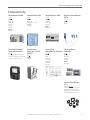
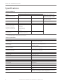
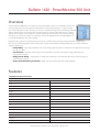
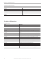
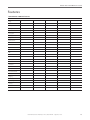
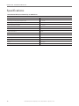
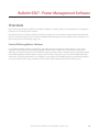
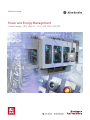
Selection Guide
Power and Energy Management
Catalog Numbers 1407, 1408, 1411, 1413, 1420, 1425, 1426, 9307

What’s Inside
Topic
Contents
Page
Bulletin 1426 - PowerMonitor 5000 Unit
Provides functions and specifications for the PowerMonitor™ 5000 unit
6
Bulletin 1420 - PowerMonitor 500 Unit
Provides functions and specifications for the PowerMonitor 500 unit
9
Bulletin 1408 - PowerMonitor 1000 Unit
Provides functions and specifications for the PowerMonitor 1000 unit
12
Bulletin 1425 - PowerMonitor W250
Provides functions and specifications for the PowerMonitor W250 unit
16
Bulletin 1412 - PowerPad Portable Power Monitor
Provides functions and specifications for the PowerPad™ Portable Power Monitor unit
19
Bulletin 1407 - Combination Generator Control
Module
Provides functions and specifications for the CGCM unit
22
Bulletin 9307 - Power Management Software
Provides functions and specifications of the available software
26
Bulletin 1413 Capacitor Bank Controller
Provides functions and specifications for the Capacitor Bank Controller
30
Additional Resources
Resource
Description
PowerMonitor 5000 Unit User Manual, publication 1426-UM001
Provides installation instructions, wiring diagrams, configuration, and specifications for
PowerMonitor 5000 units.
PowerMonitor 5000 Optional Communication Modules Installation Instructions, publication
1426-IN002
Provides instructions for installing and removing optional communication modules.
PowerMonitor 1000 Unit Installation Instructions, publication 1408-IN001
Provides installation instructions and wiring diagrams for PowerMonitor 1000 units.
PowerMonitor 1000 Unit User Manual, publication 1408-UM001
Provides configuration and specifications for PowerMonitor 1000 units.
PowerMonitor 500 Unit User Manual, publication 1420-UM001
Provides installation instructions, wiring diagrams, configuration, and specifications for
PowerMonitor 500 units.
PowerMonitor W250 Unit User Manual, publication 1425-UM001
Provides installation instructions, wiring diagrams, configuration, and specifications for
PowerMonitor W250 units.
PowerPad Portable Power Monitor User Manual, publication 1412-UM001
Provides the features, operation, and specifications for the PowerPad Portable power monitor.
Combination Generator Control Module User Manual, publication 1407-UM001
Provides installation, configuration, start-up, and operation instructions for the CGCM unit.
FactoryTalk® EnergyMetrix™ Software User manual, publication FTALK-UM001
Provides installation, configuration, and usage information for the software.
Capacitor Bank Controller User Manual, publication 1413-UM001
Provides installation, configuration, and operation information for the Capacitor Bank Controller.
Current Transformers Selection Matrix, publication 1411-SG001
Provides selection information for choosing your current transformers.
Current Transformers Technical Data, publication 1411-TD001
Provides dimension and accuracy information for the current transformers.
2
Rockwell Automation Publication 1400-SG001B-EN-P - September 2013
Power and Energy Management Overview
Which PowerMonitor product suits your application?
Are you interested in power and energy management, power quality management, or both?
Power Management
• Do you have an energy savings initiative within your company?
• Do your utility bills currently exceed $100,000 a month?
• Is energy more than 15% of your operating costs?
• Do you plan to buy electricity in the competitive market?
• Do you want to understand where your energy is consumed?
Power Quality Management
• Do you have unplanned downtime?
• How much are you spending on downtime?
• Are you able to identify the cause of downtime?
• Are there electronics failing in your facility with no known cause?
• Do you have a good understanding of the power quality in your plant?
If you answered yes to any of these questions, we can provide a solution.
Power Management Metering
The PowerMonitor 500 unit and the PowerMonitor 1000 unit provide a power management metering option. These meter
options provide a solution for customers who are in these situations:
• You are beginning an energy savings initiative.
• You notice a spike in utility bills.
• You need demand and consumption measured.
• You have meters implemented currently and are looking for a sub-metering option.
• You want to monitor individual processes and subprocesses.
• You want to communicate this metered data back to your network via optional communication (Ethernet/IP or Serial).
Wireless Power Management Metering
Does a basic metering option suit your needs; however, a wireless option would be more useful due to ease of installation and
eliminated networking costs?
The PowerMonitor W250 unit provides consumption and demand data with wireless communication (with FactoryTalk
EnergyMetrix software).
Power Quality and Power Management Metering
Do you need a more advanced metering option with power quality features?
Do you require Class 0.2 Revenue Grade Accuracy?
Do you have compliance initiatives within your organization?
Do you require waveform capture or advanced PQ measurements?
Choose the PowerMonitor 5000 unit if you are in one or more of these areas:
• Systems integrators focusing on a power quality and/or total system energy projects
• Semi-conductor industry
• Customers with power quality issues
• Lighting industry
• Monitoring main incoming power to the facility
Rockwell Automation Publication 1400-SG001B-EN-P - September 2013
3
Power and Energy Management Overview
Metering and Accuracy Levels
PowerMonitor 5000 Unit
PowerMonitor 1000 Unit
PowerPad Portable
Power Monitor
PowerMonitor 500 Unit
PowerMonitor W250 Unit
Metering Levels
PowerMonitor W250
PowerMonitor 500
PowerMonitor 1000
PowerPad
PowerMonitor 5000
Consumption
X
X
X
X
X
Demand
X
X
X
X
X
X
X
X
X
Power quality (sag/swell,
harmonics, transients)
X
X
Waveform capture
X
X
Power factor
Accuracy levels (per standard EN62053-22)
Class 1, 1% energy accuracy
Class 0.5, 0.5% energy
accuracy
X
X
X
X
Class 0.2, 0.2% energy
accuracy
4
X
Rockwell Automation Publication 1400-SG001B-EN-P - September 2013
Power and Energy Management Overview
Connectivity
PowerMonitor 5000
PowerMonitor 500
PowerMonitor 1000
(page 6)
OUTPUTS:
Digital signal
EtherNet/IP
DeviceNet
ControlNet
KYZ signal
INPUTS:
Digital signal
(page 9)
OUTPUTS:
Digital signal
Analog signal (0…20 mA)
Modbus RTU
EtherNet/IP
(page 12)
OUTPUTS:
Modbus RTU
EtherNet/IP
KYZ signal
INPUTS:
Digital signal
PowerPad Portable
PowerMonitor Unit
Combination
Generator Control
Module
FactoryTalk
Capacitor Bank
EnergyMetrix Software Controller
(page 19)
A lightweight portable unit allowing you to
monitor power anywhere in your facility with
superior functionality and accuracy.
(page 22)
OUTPUTS:
ControlNet
(page 26)
INPUTS:
Wireless
Digital signal
Analog signal
Modbus RTU
EtherNet/IP
KYZ signal
Wireless PowerMonitor
W250
(page 16)
OUTPUTS:
Wireless
(page 30)
OUTPUTS:
Modbus RTU
EtherNet/IP
KYZ signal
INPUTS:
Digital signal
Current Transformers
(CTs)
(publication 1411-SG001)
Low voltage transformers for various power
measurement devices and applications,
including protective relays, analog devices,
transducers, and PowerMonitor products.
Rockwell Automation Publication 1400-SG001B-EN-P - September 2013
5
Bulletin 1426 - PowerMonitor 5000 Unit
Overview
Do you need a more advanced metering option with power quality features?
Do you have compliance initiatives within your organization?
The PowerMonitor 5000 unit is the next generation of high-end electric metering
products from Rockwell Automation. This new family of meters provides advanced
technology, new functionality, faster response, and superior accuracy. The M5 model
is the base version and provides an extensive range of metering functionality. The
PowerMonitor 5000 unit communicates power and energy parameters to controllers, HMI
software, and applications such as FactoryTalk EnergyMetrix software over the Ethernet
network or other optional networks. The PowerMonitor 5000 unit works with controllers
or software applications to address key customer applications including the following:
• Load profiling
• Cost allocation
• Billing and sub-billing
• Power system monitoring and control
• Demand management
• Demand response
Features
PoweMonitor 5000 Unit Features
Feature
1426-M5
1426-M6
1426-M8
Voltage inputs
X
X
X
Current inputs
X
X
X
Frequency
X
X
X
Power
X
X
X
Energy
X
X
X
Demand
X
X
X
Unbalance measurements
X
X
X
Crest factor
X
X
X
K-Factor
X
X
X
THD
X
X
X
Logs
X
X
X
Setpoints
X
X
X
Time Sync
X
X
X
Ethernet/IP
X
X
X
Rockwell Automation Publication 1400-SG001B-EN-P - September 2013
6
Bulletin 1426 - PowerMonitor 5000 Unit
PoweMonitor 5000 Unit Features
Feature
1426-M5
1426-M6
1426-M8
DeviceNet
X
X
X
ControlNet
X
X
X
Revenue Accuracy
X
X
X
USB data Export
X
X
X
Virtual wiring correction
X
X
X
Alarming
X
X
X
Configurable via webpage
X
X
X
Harmonics
X
X
Oscillography
X
X
Event Sync
X
X
Flicker
X
Interharmonics
X
Transient Detect
X
Product Selection
Cat. No.
Description
1426-M5E-A
PowerMonitor 5000 M5 unit with native Ethernet communication network
1426-M5E-CNT-A
PowerMonitor 5000 M5 unit with native Ethernet and optional ControlNet network communication
1426-M5E-DNT-A
PowerMonitor 5000 M5 unit with native Ethernet and optional DeviceNet network communication
1426-M6E-A
PowerMonitor 5000 M6 unit with native Ethernet communication network
1426-M6E-CNT-A
PowerMonitor 5000 M6 unit with native Ethernet and optional ControlNet network communication
1426-M6E-DNT-A
PowerMonitor 5000 M6 unit with native Ethernet and optional DeviceNet network communication
1426-M8E-A
PowerMonitor 5000 M8 unit with native Ethernet communication network
1426-M8E-CNT-A
PowerMonitor 5000 M8 unit with native Ethernet and optional ControlNet network communication
1426-M8E-DNT-A
PowerMonitor 5000 M8 unit with native Ethernet and optional DeviceNet network communication
Accessories
Cat. No.
Description
1426-COMM-DNT
DeviceNet optional communication module
1426-COMM-CNT
ControlNet optional communication module
1426-UPGR-56
M5 to M6 firmware upgrade
1426-UPGR-58
M5 to M8 firmware upgrade
1426-UPGR-68
M6 to M8 firmware upgrade
1426-DM
PanelView™ Component C400 terminal with factory-installed applications
Rockwell Automation Publication 1400-SG001B-EN-P - September 2013
7
Bulletin 1426 - PowerMonitor 5000 Unit
Specifications
Accuracy and Range
Accuracy in % of Reading at 25 °C (77 °F) 50/60 Hz Unity Power Factor
Attribute
Voltage sense inputs: V1, V2, V3, VN
±0.1%
VG
Applies to 1426-M5
Rating, nom/Metering Range, max
X
Line-neutral rms: 398V AC/15…660V AC
Line-line rms: 690V AC /26…1144V AC
X
Connect to power system earth ground only.
This is a functional ground.
Current sense input: I1, I2, I3, I4
±0.1%
X
5 A / 0.05 - 15.6 A rms
Frequency
±0.05 Hz
X
50 or 60 Hz / 40…75 Hz
Power functions: kW, kVA, kVAR
Demand functions: kW, kVA, kVAR
Energy functions: kWh, kVAh, kVARh
• ANSI C12.20 -2010
Class 0.2 (1)
Clause 5.5.4
• EN 62053-22 -2003
Class 0.2 (1) Accuracy
Clause 8
X
Metering update rates
One update per line cycle;
1024 samples per cycle per channel
X
(1) For catalog number 1426-M5E (PN-54351) units manufactured from July 2012…January 2013, the accuracy is Class 0.5 not Class 0.2. All other characteristics and products are not impacted. The impacted units are
those with manufacturing date codes of 0712, 0812, 0912, 1012, 1112, 1212, 0113.
General Specifications
Attribute
Maximum Rating
Voltage terminal blocks
18…14 AWG (0.75…2.5 mm2), 75 °C (167 °F) min copper wire only
Recommended torque 1.5 N•m (13.3 lb•in)
Current sensing input
12 AWG (4 mm2), 75 °C (167 °F) min copper wire only
Recommended torque N/A
Control power terminal block
22…14 AWG (0.25…2.5 mm2), 75 °C (167 °F) min copper wire only
Recommended torque 0.63 N•m (5.6 lb•in)
Input/output (I/O) terminal block
20…14 AWG (0.5…2.5 mm2), 75 °C (167 °F) min copper wire only
Recommended torque 0.63 N•m (5.6 lb•in)
Temperature, operating
-20…70 °C (4…158 °F)
Temperature, storage
-40…85 °C (-40…185 °F)
Humidity, noncondensing
5…95%
Vibration
2g
Shock, operating
30 g
Shock, nonoperating
50 g
Dielectric withstand
UL61010, EN61010
Installation location
Indoor use only
Altitude
2000 m (6560 ft) max
UL/CUL
UL 61010 listed, File E345550, for Measuring, Testing and Signal-generation Equipment and CUL
Certified.
CE Certification
If this product bears the CE marking, it is approved for installation within the European Union
and EEA regions. It has been designed to meet the following directives.
8
Rockwell Automation Publication 1400-SG001B-EN-P - September 2013
Bulletin 1420 - PowerMonitor 500 Unit
Overview
The PowerMonitor 500 unit is an AC power monitor with a built-in advanced configuration system and
LCD data display. The unit is designed for measurement of electrical parameters in a variety of threephase and single-phase circuits. The unit is enclosed in a modular housing for panel mounting, with IP65
degree of protection in front of the panel. The power monitor can be provided with analog or digital
outputs. These outputs can be selected to output a pulse proportional to the real and reactive energy
measured, or to annunciate alarms. The instrument can also be equipped with a serial RS-485/RS-232
port, an EtherNet/IP port, and analog outputs.
Equipped with an optional communication port, the unit communicates power and energy parameters to applications,
such as FactoryTalk EnergyMetrix software. The power monitor works with these software applications to address these key
customer applications:
• Load profiling - log power parameters, such as real energy, apparent power, and demand, for analysis of power usage
by loads over time
• Cost allocation - reporting actual energy cost by department or process to integrate energy information into
management decisions
• Billing and sub-billing - charging users of energy the actual usage cost rather than allocating by square footage or
other arbitrary methods
• Power system monitoring and control - display and control power flow and energy utilization
Features
PowerMonitor 500 Unit Features
Feature
Availability
Voltage
X
Current
X
Frequency
X
Consumption
X
Demand
X
Voltage unbalance
X
Current unbalance
X
kW
X
kVAR
X
kVA
X
True Power Factor
X
kWh
X
kVARh
X
kVAh
X
kW Demand
X
kVAR Demand
X
Rockwell Automation Publication 1400-SG001B-EN-P - September 2013
9
Bulletin 1420 - PowerMonitor 500 Unit
PowerMonitor 500 Unit Features
Feature
Availability
kVA Demand
X
Demand Power Factor
X
Analog Output (0…20 mA)
X (1)
Pulse (digital) Output
X (1)
RS-485
X (1)
EtherNet/IP
X (1)
(1) These features are optional.
Product Selection
Available Product
Cat. No.
Description
1420-V1
PowerMonitor 500 power meter indicator, 240V AC V-LL 120V AC V-LN/240V AC V-LL
1420-V1P
PowerMonitor 500 power meter, 240V AC V-LL 120V AC V-LN/240V AC V-LL, pulse (digital) output
1420-V1A
PowerMonitor 500 power meter, 240V AC V-LL 120V AC V-LN/240V AC V-LL, analog output
1420-V1-ENT
PowerMonitor 500 EtherNet/IP power meter, 240V AC V-LL 120V AC V-LN/240V AC V-LL
1420-V1P-485
PowerMonitor 500 serial power meter, 240V AC V-LL 120V AC V-LN/240V AC V-LL, pulse (digital) output
1420-V1P-ENT
PowerMonitor 500 EtherNet/IP power meter, 240V AC V-LL 120V AC V-LN/240V AC V-LL, pulse (digital)
output
1420-V1P-485
PowerMonitor 500 serial power meter, 240V AC V-LL 120V AC V-LN/240V AC V-LL, pulse (digital) output
1420-V1A-ENT
PowerMonitor 500 EtherNet/IP power meter, 240V AC V-LL 120V AC V-LN/240V AC V-LL, analog output
1420-V1A-485
PowerMonitor 500 serial power meter, 240V AC V-LL 120V AC V-LN/240V AC V-LL, analog output
1420-V2
PowerMonitor 500 power meter indicator, 400V AC V-LN and 600V AC V-LL
1420-V2P
PowerMonitor 500 power meter , 400V AC V-LN and 600V AC V-LL, pulse (digital) output
1420-V2A
PowerMonitor 500 power meter, 400V AC V-LN and 600V AC V-LL, analog output
1420-V2-ENT
PowerMonitor 500 EtherNet/IP power meter, 400V AC V-LN and 600V AC V-LL
1420-V2-485
PowerMonitor 500 serial power meter, 400V AC V-LN and 600V AC V-LL
1420-V2P-ENT
PowerMonitor 500 EtherNet/IP power meter, 400V AC V-LN and 600V AC V-LL, pulse (digital) output
1420-V2P-485
PowerMonitor 500 Serial power meter, 400V AC V-LN and 600V AC V-LL, pulse (digital) output
1420-V2A-ENT
PowerMonitor 500 EtherNet/IP power meter, 400V AC V-LN and 600V AC V-LL, analog output
1420-V2A-485
PowerMonitor 500 serial power meter, 400V AC V-LN and 600V AC V-LL, analog output
10
Rockwell Automation Publication 1400-SG001B-EN-P - September 2013
Bulletin 1420 - PowerMonitor 500 Unit
Specifications
General Specifications
Attribute
Value
Temperature, operating
-25…55 °C (-13…131 °F) (R.H. from 0…90% noncondensing @ 40 °C) according to
EN62053-21, EN50470-1 and EN62053- 23
Temperature, storage
-30…70 °C (-22…158 °F) (R.H. < 90% noncondensing @ 40 °C) according to EN62053-21,
EN50470-1 and EN62053- 23
Installation category
Cat. III (IEC60664, EN60664)
Dielectric strength
4 kV AC rms for 1 minute
Noise rejection CMRR
100 dB, 48…62 Hz
EMC
According to EN62052-11
Electrostatic discharge
15 kV air discharge
Immunity to radiated electromagnetic fields
Test with current: 10V/m from 80…2000 MHz
Test without any current: 30V/m from 80…2000 MHz
Burst
On current and voltage measuring inputs circuit: 4 kV
Immunity to conducted disturbances
10V/m from 150 KHz…80 MHz
Surge
On current and voltage measuring inputs circuit: 4 kV; on ‘L’ auxiliary power supply input: 1 kV
Radio frequency suppression
According to CISPR 22
Standard Compliance
Safety
IEC60664, IEC61010-1 EN60664, EN61010-1
Metrology
EN62052-11, EN62053-21, EN62053-23, EN50470-3. MID ‘annex MI-003’
Pulse output
DIN43864, IEC62053-31
Approvals
CE, cULus (E56639)
Connections
Screw-type
Cable cross-section area
2.5 mm2 (14 AWG) max
Screw tightening torque: 0.4 N•m min/0.8 N•m max
Suggested screw tightening torque: 0.5 N•m
Housing DIN
Dimensions (WxHxD), approx
Module holder: 96 x 96 x 50 mm
‘A’ and ‘B’ type modules: 89.5 x 63 x 16 mm
‘C’ type module: 89.5 x 63 x 20 mm
Depth behind panel, max
81.7 mm (3.2 in.)
Material
ABS, self-extinguishing: UL 94 V-0
Mounting
Panel mounting
Pollution degree
2
Front
IP65, NEMA4x, NEMA12
Screw terminals
IP20
Weight, approx
400 g (0.88 lb) (packing included)
Rockwell Automation Publication 1400-SG001B-EN-P - September 2013
11
Bulletin 1408 - PowerMonitor 1000 Unit
Overview
The PowerMonitor 1000 unit is a compact, cost-effective, electric power and energy metering
device intended for use in industrial control applications, such as distribution centers, industrial
control panels, and motor control centers. The power monitor measures voltage and current in an
electrical circuit, meeting revenue accuracy standards. The power monitor communicates power
and energy parameters to applications, such as FactoryTalk EnergyMetrix, over Ethernet or serial
networks. The power monitor works with these software applications to address the following key
customer applications:
• Load profiling – log power parameters, such as real power, apparent power, and demand, for analysis of power usage
by loads over time
• Cost allocation – reporting actual energy cost by department or process to integrate energy information into
management decisions
• Billing and sub-billing – charging users of energy the actual usage cost rather than allocating by square footage or
other arbitrary methods
• Power system monitoring and control – display and control power flow and energy utilization
Rockwell Automation Publication 1400-SG001B-EN-P - September 2013
12
Bulletin 1408 - PowerMonitor 1000 Unit
Features
PowerMonitor 1000 Unit Features
Features
TR1
TR2
EM1
EM2
Voltage
X
X
X
Current
X
X
X
Frequency
X
X
X
Consumption
X
Demand
X
Analog output
X
Pulse (digital) output
X
Voltage unbalance
X
X
X
Current unbalance
X
X
X
kW
X
X
kVAR
X
X
kVA
X
X
True Power Factor
X
kWh
X
X
kVARh
X
X
kVAh
X
X
kW demand
X
X
kVAR demand
X
X
kVA demand
X
X
Projected kW demand
X
X
Projected kVAR demand
X
X
Projected kVA demand
X
X
Demand power factor
X
X
X
Energy log
Min/Max log
X
X
X
Load factor log
EM3
X
X
X
X
X
X
Status log
X
X
X
X
X
RS-485
X
X
X
X
X
Ethernet
X
X
X
X
X
Rockwell Automation Publication 1400-SG001B-EN-P - September 2013
13
Bulletin 1408 - PowerMonitor 1000 Unit
Product Selection
Available Product
Cat. No.
Description
1408-TR1A-485
PowerMonitor 1000 voltage and current transducer with serial network communication
1408-TR1A-ENT
PowerMonitor 1000 voltage and current transducer with Ethernet network communication
1408-TR2A-485
PowerMonitor 1000 voltage, current, and power transducer with serial network communication
1408-TR2A-ENT
PowerMonitor 1000 voltage, current, and power transducer with Ethernet network
communication
1408-EM1A-485
PowerMonitor 1000 KWh submeter with serial network communication
1408-EM1A-ENT
PowerMonitor 1000 KWh submeter with Ethernet network communication
1408-EM2A-485
PowerMonitor 1000 energy and demand monitor with serial network communication
1408-EM2A-ENT
PowerMonitor 1000 energy and demand monitor with Ethernet network communication
1408-EM3A-485
PowerMonitor 1000 energy, demand, and power monitor with serial network communication
1408-EM3A-ENT
PowerMonitor 1000 energy, demand, and power monitor with Ethernet network
communication
Specifications
Technical Specifications
Accuracy in % of Reading at 25 °C (77 °F) 50/60 Hz Unity Power Factor
Applies to
Attribute
TR1
TR2
EM1
EM2
EM3
Nominal / Range
Voltage sense inputs:
V1, V2, V3
±0.5%
X
X
X
Line-neutral rms:
347V / 15…399V
Line-line rms:
600V / 26…691V
Current sense input:
I1, I2, I3
±0.5%
X
X
X
5A / 0.05…10.0 A rms
Frequency
±0.05 Hz
X
X
X
50 or 60 Hz /
40…75 Hz
X
X
Power functions: kW,
kVA, kVAR
Demand functions:
kW, kVA
EN6205321:2003 Accuracy
Requirement Class 1
Energy functions:
kWH, kVAH
Metering update
rates
14
100 ms V, I, Hz
200 ms Power
X
X
X
X
kWh only
X
X
X
X
X
Rockwell Automation Publication 1400-SG001B-EN-P - September 2013
Bulletin 1408 - PowerMonitor 1000 Unit
Input and Output Specifications
Attribute
Value
Control power
85…264V AC 47…63 Hz
125…250V DC
4VA max
Voltage sense inputs: V1, V2, V3
Input impedance: 5 M Ω min
Input current: 2 mA max
Current sense inputs: I1, I2, I3
Overload withstand:
15 A continuous, 200 A for 1/2 s
Burden: 0.05V A
Impedance: 0.002 W
Max crest factor at 5 A is 3.0
Starting current: 5 mA
Status inputs
Contact closure (internal 24V DC)
KYZ output
80 mA at 240V AC / 300V DC
Environmental Specifications
Attribute
Dielectric withstand
Value
Control power
2500V
Voltage inputs
2500V
Current inputs
2500V
Status inputs
2500V
KYZ output
2500V
Terminal blocks
0.34…2.5 mm (22…14 AWG), 75 °C (167 °F) min copper wire only
Recommended torque 0.8 N•m (7 lb•in)
Temperature, operating
-10…60 °C (14…140 °F)
Temperature, storage
-40…85 °C (-40…185 °F)
Humidity , noncondensing
5…95%
Vibration
2.0 g 10…500 Hz
Shock, operating
30 g peak each axis
Shock, nonoperating
50 g peak each axis
2
Rockwell Automation Publication 1400-SG001B-EN-P - September 2013
15
Bulletin 1425 - PowerMonitor W250 Unit
Overview
The PowerMonitor W250 family includes a selection of power monitors, receivers, and
routers that communicate wirelessly in a mesh arrangement designed for robust, reliable
energy data collection.
The PowerMonitor W250 unit consists of three main parts:
• Wireless power monitor - The PowerMonitor W250 unit is a sub-meter that
measures and calculates several electrical parameters. The unit is equipped with
pre-wired split core current transformers or Rogowski coils and embedded wireless
data transmission capabilities.
• Wireless PC receiver - The receiver is a standalone gateway that manages the wireless network and collects data
periodically sent by PowerMonitor W250 units. The receiver transmits data through its serial port to the data logging
system for analysis. An optional, user-provided serial to Ethernet converter connects the receiver to your local area
network.
• Wireless router - The router is a repeater that extends the distance of the wireless transmission range and can provide
multiple signal paths between the PowerMonitor W250 unit and the receiver when needed.
Features
Does a basic metering option suit your needs; however, a wireless option would be more useful due to ease of installation and
eliminated networking costs?
PowerMonitor W250 Unit Features
Feature
Availability
Accuracy
X
Demand (requires RSEnergyMetrix® software version 1.8 software or later; or FactoryTalk
EnergyMetrix software version 2.0 or later)
X
Consumption
X
Voltage in interval, min
X
Current in interval, max
X
Frequency
X
DIN rail mountable
X
Time stamp
X
Wireless
X
Ethernet connection
X
Serial connection
X
Integrated CTs
X
Rockwell Automation Publication 1400-SG001B-EN-P - September 2013
16
Bulletin 1425 - PowerMonitor W250 Unit
Product Selection
Unlike other power monitor offerings, the PowerMonitor W250 unit comes with integrated current transformers, wiring mode,
and voltage ratings. Be sure to select the appropriate meter for the electrical system being metered.
Available Product
Cat. No.
Description
1425-D1002-MOD
PowerMonitor wireless, 100A, 300V delta
1425-D1002-MOD-480
PowerMonitor wireless, 100A, 480V delta
1425-W1003-MOD
PowerMonitor wireless, 100A, 300V wye
1425-D2002-MOD
PowerMonitor wireless, 200A, 300V delta
1425-W2003-MOD
PowerMonitor wireless, 200A, 300V wye
1425-D5002-MOD
PowerMonitor wireless, 500A, 300V delta
1425-D5002-MOD-480
PowerMonitor wireless, 500A, 480V delta
1425-W5003-MOD
PowerMonitor wireless, 500A, 300V wye
1425-D10002-MOD
PowerMonitor wireless, 1000A, 300V delta
1425-W10003-MOD
PowerMonitor wireless, 1000A, 300V wye
1425-D20002-MOD
PowerMonitor wireless, 2000A, 300V delta
1425-D20002-MOD-480
PowerMonitor wireless, 2000A, 480V delta
1425-GAT10
PowerMonitor wireless PC receiver, 10 nodes
1425-GAT100
PowerMonitor wireless PC receiver, 100 nodes
1425-GAT200
PowerMonitor wireless PC receiver, 200 nodes
1425-ADR1
PowerMonitor adapter, US
1425-ADR2
PowerMonitor adapter, EMEA
1425-ADR3
PowerMonitor adapter, UK
1425-W20003-MOD
PowerMonitor wireless, 2000A, 300V wye
1425-NOD
Wireless power monitor router
1425-ADR1
PowerMonitor router adapter, US
1425-ADR2
PowerMonitor router adapter, EMEA
1425-ADR3
PowerMonitor router adapter, UK
Rockwell Automation Publication 1400-SG001B-EN-P - September 2013
17
Bulletin 1425 - PowerMonitor W250 Unit
Specifications
PowerMonitor W250, Line Powered up to 300V AC rms
Attribute
Value
Primary nom current
20…2000 A (depending on the model)
Primary voltage, measuring range (neutral/phase) (VPN)
90…300V rms
Primary voltage, nom range (N/L) (VPN)
100…272V rms
Absolute min/max input voltage (N/L)
90 …300V rms
Frequency
50/60 Hz
Power consumption, max
2W
Supply current, max (N-L1)
0.2 A rms
Temperature, ambient operating (90% rH) (TA)
-10 …55 °C (14…131 °F)
Altitude
Up to 2000 m (6562 ft)
Protection degree
IP2X (for indoor use only)
Pollution degree
PD2
Isolation
Isolation class II
IEC 61010-1 CAT III
300V rms
18
Rockwell Automation Publication 1400-SG001B-EN-P - September 2013
Bulletin 1412 - PowerPad Portable Power Monitor
Overview
The PowerPad power monitor is a three-phase power quality analyzer that is easy-to-use, compact, and
shock-resistant. It is intended for technicians and engineers to measure and carry out diagnostic work on
one-, two-, or three-phase low voltage networks.
You can obtain instant waveforms of an electrical network’s principal characteristics, and also monitor
their variation over a period of time. The multi-tasking measurement system simultaneously handles all of the measurement
functions of the various magnitudes, detection, continuous recordings, and their display without any constraints.
Features
The PowerPad power monitor has the following features:
• Measurement of rms voltages up to 480V (phase-to-neutral) or 830V (phase-to-phase) for two, three, or four-wire
systems
• Measurement of rms currents up to 6500 A rms
• Frequency measurement (10…70 Hz systems)
• Calculation of neutral current for wye configurations
• Calculation of Crest Factors for current and voltage
• Calculation of the K Factor for transformers
• Calculation of short-term flicker for voltage
• Calculation of the phase unbalance for voltage and current (3 phase systems only)
• Measurement of harmonic angles and rates (referenced to the fundamental or rms value) for voltage, current or power,
up to 50th harmonic
• Calculation of overall harmonic distortion factors
• Monitoring of the average value of any parameter, calculated over a period running from 5 seconds to 2 hrs
• Measurement of active, reactive, and apparent power per phase and their respective sum total
• Calculation of the power factor, displacement power factor, and tangent factor
• Total power from a point in time, chosen by the operator
• Recording, time stamping, and characterization of disturbance (swells, sags, and interruptions, exceeding power and
harmonic thresholds)
• Detection of transients and recording of associated waveforms
Rockwell Automation Publication 1400-SG001B-EN-P - September 2013
19
Bulletin 1412 - PowerPad Portable Power Monitor
Product Selection
Cat. No.
Description
1412-PP2127-48
PowerPad portable power monitor with MN93 240 A current probes
1412-PP2127-49
PowerPad portable power monitor with SR193 1200 A current probes
1412-PP2127-50
PowerPad portable power monitor with 24 in. AmpFlex 193-24 6500 A current probes
1412-PP2127-51
PowerPad portable power monitor with 36 in. AmpFlex 193-36 6500 A current probes
Specifications
General Specifications
Attribute
Reference Conditions
Temperature, ambient
23 °C ±3 °C (73 °F ±5 °F)
Humidity
45%
Atmospheric pressure
25.4…31.3 in. Hg (860…1060 hPa)
Phase voltage
230V rms and 110V rms ±2% without DC
Clamp current circuit input voltage
0.03…1V rms without DC (<0.5%)
AmpFlex current circuit input voltage
11.8…118 mV rms without DC (<0.5%)
Frequency of electricity network
50 and 60 Hz ±0.1 Hz
V/I phase shift
0° active power / 90° reactive power
Harmonics
<0.1%
Mechanical Specifications
Attribute
Value
Dimensions, approx
240 x 180 x 55 mm (9.5 x 7.0 x 2.0 in.)
Weight, approx
2.1 kg (4.6 lb)
Altitude, operating
0…2000 m (6560 ft)
Altitude, nonoperating
0…10,000 m (32,800 ft)
Voltage Inputs
Attribute
Value
Operating range
Phase-Phase - 960V rms AC/DC Phase-Neutral 480V rms AC/DC
Input impedance
340 k: between phase and neutral
Overload
1.2Vn permanently; 2Vn for 1 s (Vn = nom voltage)
Current Inputs
Attribute
Value
Operating range
0 …1V
Input impedance
100 k: for current probe circuit and 12.4 k: for AmpFlex circuit
Overload
1.7V
20
Rockwell Automation Publication 1400-SG001B-EN-P - September 2013
Bulletin 1412 - PowerPad Portable Power Monitor
Safety Compatibility
Specifi ation
Value
Electrical safety (per EN 61010-1)
Double insulation 600V rms, Category III, Pollution Degree 2
Electromagnetic Compatibility
Immunity and emission
EN 61236-1 amendment 1
Electrostatic discharges
IEC 1000-4-2
Radiation field resistance
IEC 1000-4-3
Fast transients resistance
IEC 1000-4-4
Electric shock resistance
IEC 1000-4-5
Conducted RF interference
IEC 1000-4-6
Mechanical Protection
Shock and vibration
EN 61010-1
IP 50
EN 60529 (electrical IP2X for the terminals)
Rockwell Automation Publication 1400-SG001B-EN-P - September 2013
21
Bulletin 1407 - Combination Generator Control
Module
Overview
The Combination Generator Control Module (catalog number 1407-CGCM) is a
programmable automatic generator controller that maintains the generator output
voltage within specific limits by controlling the current applied to the exciter field
of the generator. The controller consists of a single design to regulate brush-less
permanent magnet excited generators and brush-less self excited generators.
The CGCM performs voltage regulation via control of exciter field current provided to
the generator stator.
Product Selection
The Combination Generator Control Module is a product specifically designed to protect and synchronize generators in
control applications. This includes generator protection, excitation control, synchronization control, and full-function metering.
Cat. No.
Description
1407-CGCM
Combination Generator Control Module
Features
The CGCM has the following features.
Generator Regulation and Control Functions
•
•
•
•
•
•
•
•
•
•
•
•
•
•
Four excitation control modes
Automatic voltage regulation (AVR)
Manual or field current regulation (FCR)
Power factor (PF)
Reactive power (VAR)
Soft start voltage buildup with an adjustable ramp in AVR and FCR control modes
Overexcitation (OEL) and underexcitation (UEL) limiting in AVR, VAR, and PF control modes
Underfrequency compensation (Volts/Hertz)
Line Drop Compensation
Auto-tracking between operating modes and between redundant CGCM units
Automatic transfer to a backup CGCM unit in redundant systems
Generator paralleling with reactive droop compensation or crosscurrent (reactive differential) compensation
Generator paralleling with real power load sharing
Synchronizing for 1 or 2 circuit breakers
Rockwell Automation Publication 1400-SG001B-EN-P - September 2013
22
Bulletin 1407 - Combination Generator Control Module
Generator Protection Functions
•
•
•
•
•
•
•
•
•
•
•
•
•
Loss of excitation current (40)
Overexcitation voltage (59F)
Generator overvoltage (59)
Generator undervoltage (27)
Loss of sensing (60FL)
Loss of permanent magnet generator (PMG/Excitation power) (27)
Reverse VAR (40Q)
Overfrequency (81O)
Underfrequency (81U)
Reverse power (32R)
Rotating diode monitor
Phase rotation error (47)
Generator overcurrent (51)
Metering Functions
•
•
•
•
•
•
•
•
•
•
•
•
•
•
Voltage
Current
Frequency
Real power
Apparent power
Reactive power
Power factor
Real energy (kWh)
Apparent energy (kVAh)
Reactive energy (kVARh)
Controller excitation current and voltage
Diode monitor ripple level
Load share error
Synchronization parameters
Inputs and Outputs
Inputs
•
•
•
•
•
•
Single-phase or three-phase true rms generator voltage sensing
Single-phase dual bus or three-phase single bus voltage sensing
Three-phase generator current sensing (1 or 5 A nominal)
Single-phase cross current loop 1 or 5 A current transformer (CT)input
Auxiliary ±10V DC input providing remote control of the setpoints
DC power input
Outputs
•
•
•
•
Pulse-width modulated output power stage rated at 15 A
Discrete redundancy relay output
Discrete fault output driver
Load sharing connection for use with Allen-Bradley® 1402-LSM Line Synchronization Module or compatible hardware
Rockwell Automation Publication 1400-SG001B-EN-P - September 2013
23
Bulletin 1407 - Combination Generator Control Module
Communication Interfaces
The CGCM has three communication ports:
• Redundant ControlNet connector
• RS-232 port for dedicated communication with a redundant CGCM
• RS-232 port for factory configuration and test (not for customer use)
Specifications
Control Power
Supply
Burden
18…32V DC (24V DC nom)
30 W
AC ripple, max
50%, 50…120 Hz
Operating Power Requirements
Source
Phases
Wiring Configu ation
Voltage
Frequency
VA (max)
PMG (1)
1-phase
PMG-A and PMG-C
79V rms, min
300V rms, max
50 Hz, min
240 Hz, max
3070
PMG
3-phase
Floating wye
137V rms L-L, min
300V rms L-L, max
50 Hz, min
240 Hz, max
3070
SE (2)
1-phase
PMG-A and PMG-C
79V rms, min
300V rms, max
50 Hz, min
240 Hz, max
3070
SE
3-phase
Floating wye
137V rms L-L , min
300V rms L-L, max
50 Hz, min
240 Hz, max
3070
SE
3-phase
Grounded wye
(Grounded neutral)
137V rms L-L, min
300V rms L-L, max
50 Hz, min
240 Hz, max
3070
SE
3-phase
Floating delta
137V rms L-L, min
300V rms L-L, max
50 Hz, min
240 Hz, max
3070
SE
3-phase
Open delta, floating
137V rms L-L, min
300V rms L-L, max
50 Hz, min
240 Hz, max
3070
(1) PMG = Permanent Magnet Generator
(2) SE = Separately Excited
Generator Voltage Sensing Values
Phase
Wiring Configu ation
Grounded Connection Available Voltage
1-phase
V Gen A and V Gen C
No
57V rms, min
150V rms, max
20 Hz, min
90 Hz, max
3-phase
Floating wye
No
99V rms L-L , min
208V rms L-L, max
20 Hz, min
90 Hz, max
3-phase
Grounded wye
(grounded neutral)
Yes
99V rms L-L , min
208V rms L-L, max
20 Hz, min
90 Hz, max
3-phase
Open delta, grounded ‘B’
phase
Yes
99V rms L-L , min
150V rms L-L, max
20 Hz, min
90 Hz, max
24
Rockwell Automation Publication 1400-SG001B-EN-P - September 2013
Frequency
Bulletin 1407 - Combination Generator Control Module
Generator Current Sensing
Attribute
Value
Type
3-phase plus cross current compensation input
Frequency
50/60 Hz
Range
1 A or 5 A max continuous
Burden
<0.1VA per phase for metering CTs
<2.5VA per phase for cross current inputs
Bus Voltage Sensing Values
Phase
Wiring Configu ations
Grounded Connection Available Voltage
Frequency
1-phase
V Bus A and V Bus C
No
57V rms, min
150V rms, max
20 Hz, min
90 Hz, max
3-phase
Floating wye
No
99V rms L-L, min
208V rms L-L, max
20 Hz, min
90 Hz, max
3-phase
Grounded wye (Grounded neutral)
Yes
99V rms L-L, min
208V rms L-L, max
20 Hz, min
90 Hz, max
3-phase
Open delta, grounded ‘B’ phase
Yes
99V rms L-L, min
150V rms L-L, max
20 Hz, min
90 Hz, max
Voltage Input
Attribute
Value
Range
-10…10V DC
Input impedance
20k Ω
Rockwell Automation Publication 1400-SG001B-EN-P - September 2013
25
Bulletin 9307 - Power Management Software
Overview
Power and Energy Management software is available for simple and complex systems. This software helps you configure our
products and access energy data in real time.
Our software also lets you capture, analyze, store, and share energy data across your entire enterprise through standard web
browsers. This makes it easy for you to acquire and distribute the knowledge you need to optimize energy consumption and
improve productivity while lowering energy costs.
FactoryTalk EnergyMetrix Software
FactoryTalk EnergyMetrix software is sophisticated, web-enabled energy management software that puts critical energy
information at your desktop. The FactoryTalk EnergyMetrix software suite combines data communication, client-server
applications, and the Microsoft advanced .Net web technology to provide you with a complete energy management solution.
FactoryTalk EnergyMetrix software captures, analyzes, stores, and shares energy data across your entire enterprise. By using a
web browser, your energy information is now available on your company’s LAN or WAN, presenting you with the knowledge
necessary to optimize your energy consumption. The net result is improved productivity and lower energy costs.
Rockwell Automation Publication 1400-SG001B-EN-P - September 2013
26
Bulletin 9307 - Power Management Software
Selection Comparison
Application
FactoryTalk EnergyMetrix
RSView®
Load profiling
X
Cost allocation
X
X
Power quality monitoring
X
X
Distribution system monitoring
X
X
Demand management
X
X
Energy load shedding
X
X
Power system control
X
X
Product Selection
FactoryTalk EnergyMetrix
Description
Cat. No.
FactoryTalk EnergyMetrix Manager with standard reports and charting capability. Includes 10 meters that can be used in any
combination of Allen-Bradley meters and OPC. No SQL license.
9307-FTEMMENE
FactoryTalk EnergyMetrix Manager with standard reports and charting capability. Includes 10 meters that can be used in any
combination of Allen-Bradley meters and OPC. Single Client SQL license.
9307-FTEMMDBCENE
FactoryTalk EnergyMetrix Manager with standard reports and charting capability. Includes 10 meters that can be used in any
combination of Allen-Bradley meters and OPC. Unlimited Client SQL license.
9307-FTEMMDBPENE
FactoryTalk EnergyMetrix OPC license. Allows for use of OPC with manager above 10 meters. OPC meters are unlimited with this
license but require purchase of additional meter bundles.
9307-FTEMOPC
FactoryTalk EnergyMetrix Real Time
9307-FTEMRT
FactoryTalk EnergyMetrix Charts Plus
9307-FTEMCHT
FactoryTalk EnergyMetrix Reports Plus
9307-FTEMRPT
FactoryTalk EnergyMetrix Bundle of 10 meters, requires Manager
9307-FTEM10
FactoryTalk EnergyMetrix Bundle of 50 meters, requires Manager
9307-FTEM50
FactoryTalk EnergyMetrix Bundle of 100 meters, requires Manager
9307-FTEM100
FactoryTalk EnergyMetrix Bundle of 500 meters, requires Manager
9307-FTEM500
Rockwell Automation Publication 1400-SG001B-EN-P - September 2013
27
Bulletin 9307 - Power Management Software
Features
FactoryTalk EnergyMetrix Software
Base Package: FactoryTalk EnergyMetrix Manager
• Base package
• Set up groups, domains, roles, users, devices, meters
• Log data from Allen-Bradley devices
• Basic reports and charts
• Rate schedules and billing reports
• 10, 50, 100, or 500 meter licensing
Offered with or without Microsoft SQL Server 2005 Runtime license
Optional Packages
FactoryTalk EnergyMetrix ReportsPlus
FactoryTalk EnergyMetrix ChartsPlus
FactoryTalk EnergyMetrix OPC Client
FactoryTalk EnergyMetrix RT
Optional package
Optional package
Optional package
Optional package
Enhanced reports
Enhanced charts
Enables OPC Client in Manager
Configure Allen-Bradley power monitors
Flexible formatting tools for customizing
Requires customer provided OPC server
View real-time data from Allen-Bradley power
monitors
Scalability
FactoryTalk EnergyMetrix software interfaces to your existing systems through standard protocols and has the scalability to add
additional components while maintaining your original investments:
• FactoryTalk EnergyMetrix Manager: The core data logging, reporting, charting, and billing package. Manager is a
server-based, web-enabled application that runs on a Windows 2008 server or workstation. Microsoft Internet Explorer
accesses and configures Manager. FactoryTalk EnergyMetrix Manager is available with 10, 50, 100, or 500 meters licenses.
• FactoryTalk EnergyMetrix RT: The real-time communication, configuration, and data display package of FactoryTalk
EnergyMetrix software. RT is available with FactoryTalk EnergyMetrix Manager or as a standalone package.
• FactoryTalk EnergyMetrix OPC Client: Provides connectivity to meters other than Allen-Bradley power monitors. Like
Manager, the 3PX package is offered in 10, 50, 100, and 500 meter licenses.
• FactoryTalk EnergyMetrix ReportsPlus: Creates custom reports beyond the standard reports included with Manager.
• FactoryTalk EnergyMetrix ChartsPlus: Creates custom charting capabilities above the standard charts included with
Manager.
Connectivity
Connect to metering points right from your desktop PC:
• Connectivity through RSLinx software: RS-232, RS-485, Ethernet, DeviceNet, remote I/O pass-thru, optical, and modem
(RSLinx Lite software is included with the Manager package)
• Third-party connectivity - OPC
28
Rockwell Automation Publication 1400-SG001B-EN-P - September 2013
Bulletin 9307 - Power Management Software
Configuration
FactoryTalk EnergyMetrix software provides easy and flexible configuration:
• Configure electricity, gas, water, and steam meters or any energy or production related inputs
• Configure manual meters as placeholders in the database for manual data entry
• Configure user-defined data sources, such as standard PLC-5® or SLC™ hardware types or Generic OPC
• Flexible configuration lets you do the following:
-- Name your devices
-- Name your groups
-- Create sub-groups
-- Put meters in multiple groupings for cost allocation
• Set and change meter configuration values remotely
• Multi-level password protection and privileges
Monitoring and Analysis
FactoryTalk EnergyMetrix software is a powerful load profiling, cost allocation, and billing analysis tool
• Log usage, cost, and power quality data
• View any parameter in real time
• Create historical trend reports and charts
• View historical trending of individual meters and groups and save tabular data for further processing and analysis
• Establish consumption baseline and user-defined time of use periods
• Create custom rate plans by using the rate plan menu and line item scripting
• Assign rate plans to meters or groups of meters
• Import and export rate schedules in XML format
• Create and print daily or monthly cost and billing reports by the following:
-- Meter
-- Business group
-- Department
-- Site
• Create energy budgets and forecasts
• Compare and contrast alternative utility rates; do ‘what-if’ for other rate structures
• Print and store all reports and charts
Guidelines for Server
• Windows 2003 Server or Windows 2008 Server, Application Server role. For 64-bit operating systems, RSLinx Classic
software, version 2.57 CPR9 SR3 or later, must be installed. Windows 2000 Server is not supported.
• Microsoft SQL Server 2005 or 2008, installed with mixed-mode authentication (Windows and SQL). TCP/IP access must
be enabled. A system administrator SQL login must be used for the FactoryTalk EnergyMetrix software installation.
• You must have machine administrator privileges to install FactoryTalk EnergyMetrix software.
Rockwell Automation Publication 1400-SG001B-EN-P - September 2013
29
Bulletin 1413 - Capacitor Bank Controller
Overview
Designed for various capacitor bank control applications, the Allen-Bradley Bulletin 1413 Capacitor Bank Controller is a preengineered, PLC-based solution. It combines standard, off-the-shelf, Allen-Bradley hardware with application programming
necessary to perform power factor correction in one single package. The Capacitor Bank Controller is unique in its flexibility
and adaptability compared with other standard, fixed-function capacitor control products available in the market today. Start
using this powerful, affordable, and easy to use solution to help reduce power factor penalties, kW demand charges, and
release kVA loading.
The Capacitor Bank Control system consists of a MicroLogix™ 1400 controller, one or more PowerMonitor 1000 units, a
standard that is built-in the MicroLogix 1400 controller, and an optional Human-Machine Interface (HMI). Pre-engineered
programming in the controller gathers real and reactive power data from up to four power feeds including utility feeds and/
or generators. The logic operates on the data in standard engineering units of kVAR and kW and acts to minimize imported
and exported reactive power by switching up to 10 individually-switched capacitor groups. This strategy controls power factor
within specified limits while providing the flexibility to modify the system to meet the specific requirements of the application.
Product Selection
Cat. No.
MicroLogix 1400
PowerMonitor 1000
PanelView Component C600
1413-CAP-ME
Ethernet
Ethernet
None
1413-CAP-ME-PE
Ethernet
Ethernet
Benefit
•
•
•
•
•
•
•
•
•
Basic and advanced control of capacitor banks to help reduce power factor penalties and kVA demand charges
Ability to monitor and control VARs to multiple feeders
Advanced VAR control modes for precise power factor control
Simple addition of I/O for additional steps and functionality (for example, alarming)
Local and remote communication capabilities for programming, viewing, sending information, and alarming for real
time electrical system status
Easy to configure and view through an optional display module
Full functioning real time power and energy monitoring (hundreds of parameters captured, logged, and available within
the PowerMonitor unit for taking action and/or passing to other systems displayed locally and/or remotely)
Open system architectures using the familiarity with PLCs and standard off-the-shelf hardware
Seamless integration into Rockwell Automation and third- party HMI and SCADA systems
Rockwell Automation Publication 1400-SG001B-EN-P - September 2013
30
Bulletin 1413 - Capacitor Bank Controller
Features
• Auto and/or manual step size configuration
• Discharge timer on each step
• Selectable operating modes
-- Manual operation
-- First-in, Last-out (FILO)
-- Balanced – Distribute usage of capacitor steps
-- Best Fit – Finds best match of capacitor step size to system kVA needs
• Alarms
-- Bad step, indicates blown fuse, capacitor failure
-- Target power factor not achieved
-- High/Low voltage
• Power monitor data concentrated into the MicroLogix controller an displayed with an optional HMI
• Metering phase current, line voltage, frequency, real and reactive power, and power factor
Options
• Up to three additional power monitors to aggregate up to four total feeds
• PanelView Component HMI terminal with Ethernet communication
:
Rockwell Automation Publication 1400-SG001B-EN-P - September 2013
31
Allen-Bradley, Rockwell Software, Rockwell Automation, PowerMonitor, PowerPad, PanelView, MicroLogix, PLC-5, SLC, RSView, RSLinx, RSEnergyMetrix, FactoryTalk EnergyMetrix, and LISTEN. THINK. SOLVE are
trademarks of Rockwell Automation, Inc.
Trademarks not belonging to Rockwell Automation are property of their respective companies.
Publication 1400-SG001B-EN-P - September 2013
Supersedes 1400-SG001A-EN-P - May 2005
Copyright © 2013 Rockwell Automation, Inc. All rights reserved. Printed in the U.S.A.