
1
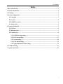
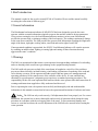
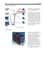
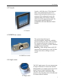
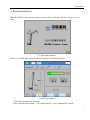
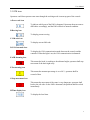
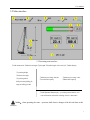
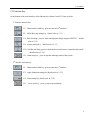
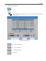
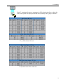
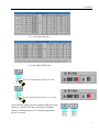
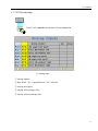
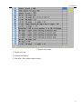
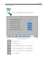
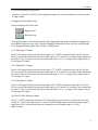
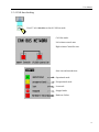
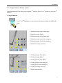
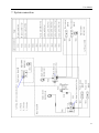
ZOOMLION
Mobile Crane Branch Company
QUY260 Load Moment Indicator
User Manual
Hirschmann Electronics (Shanghai)Co.,Ltd
Apr. 2009
User Manual
2009 by Hirschmann Electronics Co.,Ltd.
Copyright
Any reproduction, modification and translation, without official authorization in writing of Hirschmann
Electronics (Shanghai) Co.,Ltd, shall be prohibited. For reproduction of this manual please refer to
Copyright Law.
1st edition on Apr. 2009
Guarantee
The information in this document is subject to change without notice. Hirschmann makes no warranty
of any kind with regard to this material, including, but not limited to the implied warranties of
merchantability and fitness for a particular purpose. Hirschmann shall not be liable for errors contained
herein or for incidental or consequential damages in connection with the furnishing, performance, or
use of this manual.
Hirschmann Electronics(Shanghai)Co.,Ltd
Suite 10K, Huamin Empire Plaza, No.728, West Yan An Road, Shanghai, P.R.China
Tel:021-51082780
Fax:021-52375899
Zipcode:200050
Website:http://www.hirschmann-ac.com
User Manual
Index
1.Breif introduction ................................................................................................................................. 2
2.General information ............................................................................................................................. 2
3.Warnings ............................................................................................................................................... 2
4.System configuration............................................................................................................................ 3
4.1Controller ...................................................................................................................................... 3
4.2 Console ......................................................................................................................................... 4
4.3 KMD Force sensor ...................................................................................................................... 4
4.4 Angle sensor ................................................................................................................................. 4
5. System introduction ............................................................................................................................ 5
5.1 OM icon ........................................................................................................................................ 6
5.2 Main interface .............................................................................................................................. 7
5.3 Function key................................................................................................................................. 8
5.3.1 OM & Reeving setting........................................................................................................ 9
5.3.2 I/O Port checking ............................................................................................................. 12
5.3.3 System setting ................................................................................................................... 14
5.3.4 CAN-bus checking ............................................................................................................ 16
5.3.5 Angle limitation & Time setting ...................................................................................... 17
6. Trouble shooting ................................................................................................................................ 19
7. System connection ............................................................................................................................. 25
1
User Manual
1.Breif introduction
This manual is made for the crawler cranesQUY260 of Zoomlion. Please read the manual carefully
according the collocation of different types.
2.General information
The Hirschmann load moment indicator (LMI) iFLEX5 has been designed to provide the crane
operator with the essential information required to operate the machine within its design parameters.
Using various sensing devices, the Load Moment Indicator monitors various crane function and
provide the operator with a continuous reading of the load capacity. The readings continuously change
as the crane moves and lifts. The LMI provides the operator with information regarding the length and
angle of the boom, tip height, working radius, rated load and total weight of actual lift.
If non-permitted condition is approached, the iFLEX5 Load Moment Indicator will warn the operator
by sounding an audible alarm, lighting a warning light and cutting off those functions that may
aggravate the crane’s condition.
3.Warnings
The LMI is an operational aid that warns a crane operator from approaching conditions of overloading
and over-hoisting which would cause great damage to the equipment and personnel.
The LMI could only prevent overload of the crane boom in lengthwise vertical level but could not
prevent accidents caused by inclined hoisting, wind loading, inclination or foundering of the road and
rail or driving oversteps. So the operators and other people shall not ignore safe management and
operating procedures of the crane because of the existence of the device. It is not, and shall not,
substitute for a good operator’s judgment, great experience or standard operating procedures. The
responsibility for the safe crane operation shall remain with the crane operator who shall ensure that all
warnings and instructions supplied are fully understood and observed.
Prior to operating the crane, the operator must carefully and thoroughly read and understand the
information in this manual to ensure that he knows the operation and limitations of indicator and crane.
Notice:The LMI can only work correctly, if all adjustments have been properly set. For correct
adjustment, the operator has to answer thoroughly and correctly all questions asked during the setup
procedure in accordance with the real rigging state of the crane. To prevent material damage and
serious or even fatal accidents, the correct adjustment of the LMI has to be ensured before starting the
crane operation.
2
User Manual
4.System configuration
The system is composed of Expert
console, iFLEX5 controller, KMD
force sensor, angle sensor, etc.
When operator sets current OM and
reeving according to the key of the
display, the signal is transmitted to
controller and display by pull sensor.
The display shows the actual weight
and rated weight. The actual weight
and rated weight is compared in the
controller. Once the rated weight is
reached, the controller will indicate
the overloading warning signal and
send warning sound. At this moment,
operator is forbidden to operate to
dangerous direction.
4.1 System configuration
4.1 Controller
4.2 Controller
Controller: 32 digit industrial control
PLC system and high-powered
processor qualify the requirements of
bad environment for all kinds of
industrial system. IFLEX5 module is
composed of base board or base
board add expansion board.
Customers could choose different
IFLEX5 module according to their
own needs. Each module can be
connected by CANBUS. Due to the
building block mode, the IFLEX5 is
not only applicable to medium and
small control systems, but also to big
and complicated control systems.
3
User Manual
4.2 Console
Console: a 640*480 color LCD of industrial
lattice screen graph liquid crystal. It can
display all the operational data that you are
concerned. The combination between the
Graphical display and Genersys software
achieve the on-line program for graph. The
strong graph compiled capability is
incomparable with other Industrial Control
displays.
4.3 Console
4.3 KMD Force sensor
The system adopts shock-proof,
anti-electromagnetic interference, and high
precision and low zero drift. As the sensor has
the compensated function of temperature, it
can retain its own quality even with continuous
and high-intensive operation.
Remarks:all the analog sensor for iFLEX5
system must be current type or with CAN-bus.
Voltage sensor have to change to current
sensor.
4.4 KMD force sensor
4.4 Angle sensor
4.5 Angle sensor
The WGC angle sensor is for exact measurement
for angle of all kinds of construction machines.
Distinguished by its compact exterior, the sensor
has the feature of simple installation, high
efficiency and accuracy, no hysteresis, high
protective class, long time service life and suited
to extreme ambient condition.
4
User Manual
5. System introduction
When the iFLEX5 control system is power on, the console will display QUY260 crawler crane as
below:
5.1 Welcoming interface
After 4~5 seconds, main interface—the LMI interface will present as below:
5.2 LMI main interface
At 5.2, from the top to the bottom is:
Part 1: Operate State column; Part 2:main interface:
Part 3: function key column
5
User Manual
5.1 OM icon
Operators could learn present crane state through the working mode icon on top part of the console.
A.Error code icon
To indicate which part of the LMI is abnormal. Operators then can remove
difficulties accordingly, and the LMI will back to normal condition.
B.Reeving icon
To display present reeving.
C.OM code icon
To display current OM code.
D.CAN-bus mode icon
To display the CAN communication mode between the console and the
controller. When the light is on, the CAN communication is abnormal.
E.A2B alarming icon
This means the hook is reaching to the ultimate height, operators shall stop
movement of the hook right away.
F.Pre-warning icon
This means the moment percentage is over 90%, operators shall be
awared of that.
G.Stop movement icon
This means the movement of the crane is very dangerous, operators shall
back to the safe side. Or the LMI is abnormal, the problem shall be solved
immediately.
H.Time display icon
To display the local time.
6
User Manual
5.2 Main interface
5.3 Presenting main interface
①OM introduction ②Main boom length ③jib length ④Installed angle of the fixed jib ⑤Mode display
①operating height
②main boom angle
③operating radius
Still presenting luffing jib
①Moment percentage barcode
③Actual load capacity
②Moment percentage value
④Rated load capacity
angle at luffing jib OM
①LMI Operate State display(presenting normal OM or error
code information and trouble shooting when it is abnormal)
Notice:when operating the crane,operators shall observe changes of the aboved datas at this
interface
7
User Manual
5.3 Function key
At the bottom of the main interface is the function key column, from F1-F8 are as below:
1st interface function key:
F1:Main interface shift key, press to enter into 2nd interface;
F2:OM & Reeving setting key(details refer to 5.3.1);
F3:Data checking,press to check analog input & digit output of iFLEX5 (details
refer to 5.3.2)
F4:System setting key,(details refer to 5.3.3)
F5:CAN-Bus checking,press to check the bus mode between controller and console
(details refer to 5.3.4)
F8:Alarm stop key,press to stop the alarming sound of the system
2nd interface function key:
F1:Main interface shift key, press to enter into 1st interface;
F3:Angle limitation setting key (details refer to 5.3.5)
F4:Time setting key (details refer to 5.3.5)
F8: Alarm stop key,press to stop system alarming
8
User Manual
5.3.1 OM & Reeving setting
Press F2 OM & Reeving setting key at 1st interface to enter into OM & Reeving
setting interface
5.4 OM & Reeving setting
F1:OM code checking key
F4:OM code setting key
F6:Reeving setting key
F8:Enter key
9
User Manual
Press F1 (continuously press to turn pages) at OM selecting interface to check the
OM code. System will display main OM code separately into 4 pages as follows:
5.5 (a) Main boom OM code
5.5 (b) Main boom runner OM code
10
User Manual
5.5 (c) Fixed jib OM code
5.5 (d) Luffing jib OM code
Press F4 at OM selecting interface to set OM:
Press F6 at OM selecting interface to set reeving:
After finish the setting, press F8 backing to OM & Reeving
interface,press F8 once again will come out dialogue
frame of confirmation, press F7 to safe this operation or
press F1 to cancel.
11
User Manual
5.3.2 I/O Port checking
Press F3 at 1st interface to check the I/O port information
5.6 Analog input
① Analog channel
② Base board(X1)expanded board(X2)stitch No.
③ Analog description
④ Analog A/D exchange value
⑤ Analog actual measuring value
12
User Manual
5.7 Digital value output
① Digital value No.
② Function description
③ Port mode(Blue means output existing)
13
User Manual
5.3.3 System setting
Press F4 at 1st interface to enter into system setting interface
5.8 System setting interface
F1:Rigging mode key
F2:Working mode key
F3:Choose main boom angle 65° key(at Luffing jib OM)
F4:Choose main boom angle 75° key(at Luffing jib OM)
F5:Choose main boom angle 85° key(at Luffing jib OM)
F6:Cancel setting key
14
User Manual
(1) Selected Rigging/Working Mode:
Operators can press F1 and F2 to select rigging/working mode, the related mode icon will be present
at right column.
(2) Rigging/Working Mode State:
Present working mode of the crane
Rigging mode
Working mode
After rigging mode is selected, the controller will judge whether the mode could shift to rigging mode
according to the present crane OM, if it could, Rigging/Working Mode State will show rigging mode;
if not, Rigging/Working Mode State will show working mode.
(3) LJ OM angle 65°output:
Press F3 will appear that present main boom angle is 65°. If SET icon present at the top of F3 means
F3 key is pressed down and when the main boom angle is 65±1°means one switching value channel put
out. If the F3 key is not pressed, when the main boom angle is 65±1°, no output exist. Output mode is:
LJ OM angle 65°output.
(4) LJ OM angle 75°output:
Press F4 will appear that present main boom angle is 75°. If SET icon present at the top of F4 means
F4 key is pressed down and when the main boom angle is 75±1°means one switching value channel put
out. If the F4 key is not pressed, when the main boom angle is 75±1°, no output exist. Output mode is:
LJ OM angle 75°output.
(5) LJ OM angle 85°output:
Press F5 will appear that present main boom angle is 85°. If SET icon present at the top of F5 means
F5 key is pressed down and when the main boom angle is 85±1°means one switching value channel put
out. If the F5 key is not pressed, when the main boom angle is 85±1°, no output exist. Output mode is:
LJ OM angle 85°output.
(6) Cancel LJ OM MB angle output:
Press F6 , if SET icon present at the top of F6 means F6 key is pressed down. At that time cancel the
setting of 3,4 and 5, the output mode is: Cancel LJ OM MB angle output, and the main boom angle is
approved as 85±1°with one switching value channel put out, the output mode is: LJ OM
angle85°output.
15
User Manual
5.3.4 CAN-bus checking
Press F5 at 1st interface to check CAN-bus mode:
CAN-bus mode:
Left column console state
Right column Controller state
State icon and introduction:
Operational mode
Preoperational mode
Lost mode
Stopped mode
Hardware failure
16
User Manual
5.3.5 Angle limitation & Time setting
Angle limitation and Time setting is processed at 2nd interface. Press F1 at 1st interface to enter into 2nd
interface:
(1) Angle limitation
Press F3 at 2nd interface to set the limitation of main boom angle and Luffing jib
angle:
① Main boom angle upper limit display
② Main boom angle display
③ Main boom angle lower limit display
④ Main boom angle upper limit setting key
⑤ Main boom angle lower limit setting key
⑥ Main boom setting cancel key
① Luffing jib upper limit display
② Luffing jib angle display
③ Luffing jib lower limit display
④ Luffing jib upper limit setting key
Luffing jib lower limit setting key
⑥ Luffing jib setting cancel key
⑦ Back to main interface
17
User Manual
At this interface, operators can set angle limitation of main boom and luffing jib. When the crane boom
approached the limitation, press the related key, it will present SET icon on top of the key which means
the key is already pressed down. At that time, the ultimate angle will be recorded and when the boom
reach to this angle next time, system will alarm.
For example, when the main boom angle is not allowed to exceed 78° due to the operating environment,
lift the main boom to 78° and press angle limitation setting key to set the upper limit. After finish the
setting, when main boom angle exceed 78°, system will alarm operators to stop any dangerous
movement. Press F3 the setting will be canceled.
(2) Time setting
Operators can adjust time when the time displayed is not local time .Press F4 at 2nd interface to set
time:
F4:Turn left key
F5:Turn right key
F6:Value add key
F7:Value reduce key
F8:Confirm and back to main interface key
After finish the related setting, press F8 to confirm and back to main interface.
18
User Manual
6. Trouble shooting
In case of any improper operation or LMI malfunction during the crane’s operation it will display some
certain code (error code) for the user’s information. Some errors are caused by illegal operation, some
by people’s cause ad some are caused by other factors.
The following codes can be an aid and help for how to use and maintenance the LMI system:
Notice
If you cannot solve the problem according to the following contents,
please contact us as soon as possible at
Tel:021-51082780
Error
code
Malfunction
Fax:021-52375899
Cause
Solution
E01
Fallen below the radius
range or angle range
exceeded
Due to the too much hoist up of
the boom which result in lower
than the min. radius or exceed the
max. angle in the capacity chart.
Boom down to a permitted radius
or angle in the load chart.
E02
Exceed the max. radius or
lower than the min. angle.
Due to the too much hoist down
which result in exceed the max.
radius or lower than he min.
angle.
Boom up to a permitted radius or
angle in the load chart.
E04
OM not exist or exceed the
motion of rotary range
Improper OM setting or enter into
prohibited slewing area
Properly choose the OM according
to actual operation and slew back
to a permitted range.
E05
Prohibited length range
Choose a main boom length that
is not exist.
Choose a proper main boom
length.
E06
Fallen below the Minimum
angle range when luffing
down or luffing up
The jib luffing down too much
result in the actual angle is lower
than the permitted value in the
capacity chart.
Luffing up the jib to a permitted
radius or angle in the capacity
chart
Over load relay act and controller
switching value NO.20 input
channel open
Check the over load relay and
cable of the controller switching
value NO.20 input channel
Over load relay not act and
controller switching value NO.20
input channel close
Check the over load relay
E07
Over load relay checking
Check the controller switching
value NO.20 input channel
19
User Manual
Error
code
Malfunction
Cause
Solution
Sensor cable defective or plug
water inside
Change cable or plugs
KMD fault
Change KMD of main boom
Channel measuring parts broken
Change KMD parts
Sensor cable defective or plug
water inside
Change cable or plugs
KMD fault
Change KMD of jib
Channel measuring parts broken
Change KMD parts
Sensor cable defective or plug
water inside
Change cable or plugs
KMD fault
Change KMD of main boom
Channel measuring parts broken
Change KMD parts
KMD of luffing jib defective
Change KMD of luffing jib
Cable of the checking channel
defective
Change cable of the channel
Sensor cable defective or plug
water inside
Change cable or plugs
KMD fault
Change luffing jib KMD
Channel measuring parts broken
Change KMD parts
E16
“Luffing jib foot angle
sensor channel” voltage is
lower than the min.
limitation.
Refer to E15
Refer to E15
E17
“Left KMD of Luffing jib”
voltage is lower than the
min. limitation.
Refer to E14
Refer to E14
E18
“Main boom backstop
pressure sensor channel”
voltage is lower than the
min. limitation.
Refer to E14
Refer to E14
E1B
“Luffing jib top angle sensor
channel” voltage is lower
than the min. limitation.
Refer to E15
Refer to E15
E12
E13
E14
E14
E15
“Main boom right KMD
channel” voltage is lower
than the min. limitation
“Jib right KMD channel”
voltage is lower than the
min. limitation
“Main boom left KMD
channel” voltage is lower
than the min. limitation
“Right KMD of luffing jib”
voltage is lower than the
min. limitation.
“Main boom foot angle
sensor channel” voltage is
lower than the min.
limitation。
20
User Manual
Error
code
Malfunction
E1C
“Top angle sensor of main
boom” voltage is lower than
the min. limitation.
E1D
E1E
E1F
E22
E23
E24
E25
“Super lift mast angle (if
support) channel” voltage is
lower than the min.
limitation.
“KMD channel of luffing
system” voltage is lower
than the min. limitation.
“Super lift mast angle sensor
channel” voltage is lower
than the min. limitation.
“Main boom right KMD
channel” voltage exceed the
limitation.
“Jib right KMD channel”
voltage exceed the
limitation.
“Main boom KMD channel”
voltage exceed the
limitation.
“Main boom foot angle
sensor channel” voltage
exceed the limitation.
Cause
Solution
Top angle sensor of main boom
defective.
Change head angle sensor of main
boom
Cable of the checking channel
defective or unconnected
Connect or change Cable of the
checking channel
Refer to E15
Refer to E15
Refer to E14
Refer to E14
Refer to E15
Refer to E15
Refer to E12
Refer to E12
Refer to E14
Refer to E14
Refer to E14
Refer to E14
Refer to E15
Refer to E15
E26
“Luffing jib foot angle
sensor channel” voltage
exceed the limitation.
Refer to E15
Refer to E15
E27
“Angle sensor channel of
Luffing jib” voltage exceed
the limitation.
Refer to E14
Refer to E14
E28
“Main boom Main boom
backstop pressure sensor
channel” voltage exceed the
limitation.
Refer to E14
Refer to E14
E2B
“Luffing jib Top angle
sensor channel” voltage
exceed the limitation.
Refer to E15
Refer to E15
E2C
“Top angle sensor of main
boom” voltage exceed the
limitation.
Refer to E15
Refer to E15
E2D
“Super lift mast angle ( if
support ) channel” voltage
exceed the limitation.
Refer to E15
Refer to E15
21
User Manual
Error
code
E2E
E2F
E37
Malfunction
“Luffing jib system force
channel” voltage exceed the
limitation.
“Super lift mast angle sensor
checking channel” voltage
exceed the limitation.
Logical programming fault
Cause
Solution
Refer to E14
Refer to E14
Refer to E14
Refer to 14
Flash-EPROM fault
Update effective software of the
system
Change controller
Programming file fault
E38
System program does not
comply with crane data file
The LMI system program is
different from crane data file
Update effective system software
or crane data file
E39
System program does not
comply with performance
table
The LMI system program is
different from performance table
Update effective system program
or performance table
E3A
Crane data file does not
comply with performance
table
Crane data file is different from
performance table
Change data file or performance
table
E43
RAM fault
RAM or controller fault
Change controller
E51
Crane data file fault
No readable crane data file
Up date crane data file
Flash-EPROM defective
Change Flash-EPROM
No readable crane performance
table
Update crane performance table
E52
Crane performance file fault
Flash-EPROM fault
E56
E57
E60
E61
Crane data file fault
Crane serial data file fault
None-identified base file
NO. and programming value
CAN-bus data
communication fault
Change Flash-EPROM
No effective data file during
adjustment
Resume and update effective crane
data file
Flash-EPROM fault
Change controller
No effective data file in the
adjusting data file
Update effective data file
Flash-EPROM fault
Change controller
No effective data in performance
file
Update effective performance file
Unprogrammed Base file NO.
Program correct base file NO( 1 is
base1, 2 is base 2)
Performance table programming
fault
CAN-bus cable between
controller and sensor defective or
unconnected
Controller CAN-bus port fault
Checking the performance file of
program base file
CAN-bus cable short circuit
Change Can-bus cable
Check the connecting cable
between controller and sensor
Change controller
22
User Manual
Error
code
Malfunction
E80
Luffing jib system force too
big
E81
Top angle and foot angle of
main boom differ too much
Cause
Solution
Exceed the limitation of
destructive force
Reduce force of luffing system
Top or foot angle sensor of main
boom defective
Change top or foot angle sensor of
main boom
Top or foot angle sensor cable of
main boom defective
Change top or foot angle sensor
cable of main boom
Top or foot angle sensor of
Luffing jib defective
Change top or foot angle sensor of
Luffing jib
Top or foot angle sensor cable of
Luffing jib defective
Change top or foot angle sensor
cable of Luffing jib
Reduce main boom force
E82
Top angle and foot angle of
Luffing jib differ too much
E83
Main boom force value
exceed limitation of rope
destructive force
Main boom force too big
Cable of checking channel
defective
E84
Wrong rigging condition.
The selected rigging condition is
not contained in the crane data
file.
E85
Wrong setting of range
Setting range of computer is too
small (negative deviation)
Check program of crane data file
E88
Main boom position
abnormal at Luffing jib OM
Main boom angle abnormal
Main boom angle luff to allowed
range
E89
Luffing jib angle abnormal
at fixed or Luffing jib OM
E94
No data transfer from
controller to console
cable of main boom angle channel
defective
Luffing jib angle exceed allowed
range when jib luffing
Change channel cable
Select another rigging condition
Check the programming in the
crane data file.
Change channel cable
Luffing jibto allowed range
Wrong measurement of Luffing
jib angle
Check measurement of Luffing jib
angle
CAN-bus abnormal
System data communication
abnormal
Re-start the system
Check CAN-bus cable
Re-start the system
E98
EAB
EAC
LMI watch dog open
A2B switch short circuit
LMI operated overtime
Connect computer ports and
observe wrong information
A2B switch short circuit
Change A2B switch
A2B switch cable short circuit
Change A2B switch cable
A2B switch disconnect
Change or connect A2B switch
A2B switch disconnect
A2B switch cable disconnect
EAD
A2B switch inefficacy
Change or connect A2B switch
cable
Sensor function fault
Change A2B switch
CAN-bus delay
Change A2B switch cable
23
User Manual
Error
code
Malfunction
“Length checking channel
EB1
of the hoist steel wire”
Cause
No steel wire on hoist
Adjust length of steel wire
No measurable sensor exist for
Install sensor and revise this
hoisting
function at program data
Steel wire length no adjust well
voltage is lower than the
Wrong steel wire/hoist parameter
min limitation
at program data
No counter input defined at
configuration
Counter input fault
EB2
“Length checking channel
Steel wire completely twining
of steel wire on hoist”
hoist ( only possible at EB2)
voltage exceed the
limitation
EB3
Solution
Refer to EB1
“Checking channel of hook
No steel wire between hook and
height” voltage exceed the
forward oriented wheel
limitation
Refer to EB1
Adjust steel wire length and
surface
Check parameter of program data
Change I/O configuration
Change Iflex
Adjust length of steel wire
Refer to EB1
Refer to EB1
Setting RTC and change battery
EDD
Battery empty
Check out low voltage of the two
Temporary measurement:press
ports of battery
alarm stop key when
Operation without data loader
EFD
LMB watch dog overtime
This function shall be started over
5 min. like writing flash PROM
After finish programming,
information is not automatically
started
24
User Manual
7. System connection
25


![[ user manual ]](http://vs1.manualzilla.com/store/data/006917286_1-ab1d9edbe86470fcfa5481380fd001da-150x150.png)


![[ user manual ] - Electro Optical Components, Inc.](http://vs1.manualzilla.com/store/data/005883576_1-0c36e07c3044c4bd3e113418af6fccd7-150x150.png)


![[ user manual ]](http://vs1.manualzilla.com/store/data/006920003_1-d680b577f9aafbf5352b2591a509e95d-150x150.png)