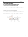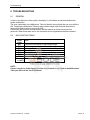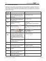
1
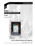
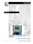
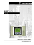
HIRSCHMANN LOAD MOMENT INDICATOR iFLEX5 vertical/horizontal console OPERATOR’S MANUAL P/N 031-300-190-147 REV E- 11/12/2008 NOTICE PAT America, Inc. makes no warranty of any kind with regard to this material, including, but not limited to, the implied warranties of merchantability and/or its fitness for a particular purpose. PAT America, Inc. will not be liable for errors contained in this manual or for incidental or consequential damages in connection with the furnishing, performance, or use of this manual. This document contains proprietary information, which is protected by copyright, and all rights are reserved. No part of this document may be photocopied, reproduced, or translated to another language without the prior written consent of PAT America, Inc. PAT America, Inc. reserves proprietary rights to all drawings, photos and the data contained therein. The drawings, photos and data are confidential and cannot be used or reproduced without the written consent of PAT America, Inc. The drawings and/or photos are subject to technical modification without prior notice. All information in this document is subject to change without notice. MANUAL REVISIONS REV A B C D E DATE 2/22/02 11/11/02 05/19/03 02/22/05 01/06/06 11/12/08 NAME MO CH SB MS SB WG DESCRIPTION ECN 02-64 ECN 02-278 ECN 03-065 ECN 05-041 ECN 05-217 ECN 08-179 © 2006 Hirschmann, Chambersburg, PA 17201, USA © Hirschmann Rev. E 11/12/08 190147_E Operator's Manual iFLEX5 TABLE OF CONTENTS 1 GENERAL INFORMATION............................................................................................................. 1 2 WARNINGS..................................................................................................................................... 1 3 SYSTEM DESCRIPTION ................................................................................................................ 2 3.1 SYSTEM FUNCTION ........................................................................................................................4 3.2 OPERATING CONSOLE ...................................................................................................................5 3.3 CONTROL IDENTIFICATION ..............................................................................................................5 4 CONFIGURATION SETUP ........................................................................................................... 11 4.1 LMI SETUP PROCEDURE ..............................................................................................................11 4.2 QUICK SETTING OF THE REEVING .................................................................................................15 4.3 QUICK HOIST LINE SELECTION .....................................................................................................16 5 OPERATION ................................................................................................................................. 17 5.1 LIMIT SETTING .............................................................................................................................20 5.1.1 Slewing Angle Limitation / Work Area Definition...........................................................21 5.1.2 Tip Height Limitation ........................................................................................................26 5.1.3 Boom Angle Limitation.....................................................................................................27 5.1.4 Radius Limitation..............................................................................................................29 5.1.5 Wind Speed .......................................................................................................................30 5.2 INFO CRANE CONFIGURATION ......................................................................................................31 5.3 DISPLAY CONTRAST CONTROL .....................................................................................................32 6 PRE-OPERATION INSPECTION AND CALIBRATION VERIFICATION ..................................... 33 6.1 6.2 6.3 6.4 6.5 MACHINES WITH ONLY A MAIN HOIST ............................................................................................33 MACHINES WITH MAIN AND AUXILIARY HOISTS .............................................................................33 INSTALLATION OF ANTI TWO-BLOCK RETAINER IN LOCKING POSITION ..........................................34 REMOVAL AND STORAGE OF THE ANTI TWO-BLOCK RETAINER .....................................................34 PRE-OPERATION INSPECTION AND CALIBRATION VERIFICATION ....................................................35 7 SERVICE AND MAINTENANCE................................................................................................... 36 8 TROUBLESHOOTING .................................................................................................................. 37 8.1 GENERAL ....................................................................................................................................37 8.2 MALFUNCTION TABLE ..................................................................................................................37 8.3 OPERATING ERRORS ...................................................................................................................38 9 10 APPENDIX A: DETAILED SYMBOL EXPLANATION OF BOOM EXTENSIONS ....................... 40 APPENDIX B:DETAILED SYMBOL EXPLANATION OF COUNTERWEIGHT OPTIONS....... 41 © Hirschmann Rev. E 11/12/08 190147_E General Information 1 1 GENERAL INFORMATION The PAT Load Moment Indicator1 (LMI) has been designed to provide the crane operator with the essential information required to operate the machine within its design parameters. Using different sensing devices, the Load Moment Indicator monitors various crane functions and provides the operator with a continuous reading of the crane’s capacity. The readings continuously change as the crane moves through the motions needed to make the lift. The LMI provides the operator with information regarding the length and angle of the boom, working radius, rated load and the total calculated weight being lifted by the crane. If non permitted conditions are approached, the Load Moment Indicator will warn the operator by sounding an audible alarm, lighting a warning light and locking out those functions that may aggravate the crane’s condition. 2 WARNINGS The LMI is an operational aid that warns a crane operator of approaching overload conditions and of overhoist conditions that could cause damage to equipment and personnel. The device is not, and shall not, be a substitute for good operator judgment, experience and use of accepted safe crane operating procedures. The responsibility for the safe crane operation shall remain with the crane operator who shall ensure that all warnings and instructions supplied are fully understood and observed. Prior to operating the crane, the operator must carefully and thoroughly read and understand the information in this manual to ensure that he knows the operation and limitations of indicator and crane. Proper functioning depends upon proper daily inspection and observance of the operating instructions set forth in this manual. Refer to Section 6. Pre-Operation Inspection and Calibration Verification of this handbook. The LMI can only work correctly, if all adjustments have been properly set. For correct adjustment, the operator has to answer thoroughly and correctly all questions asked during the setup procedure in accordance with the real rigging state of the crane. To prevent material damage and serious or even fatal accidents, the correct adjustment of the LMI has to be ensured before starting the crane operation. 1 LOAD MOMENT: generally the product of a force and its moment arm; specifically, the product of the load and the load-radius. Used in the determination of the lifting capacity of a crane © Hirschmann Rev. E 11/12/08 190147_E 2 Operator's Manual iFLEX5 3 SYSTEM DESCRIPTION The PAT Load Moment Indicator consists of a central micro processor unit, operating console, length/angle sensor, pressure transducers, and anti-two block switches. The system operates on the principle of reference/real comparison. The real value, resulting from the pressure measurement is compared with the reference data, stored in the central processor memory and evaluated in the micro processor. When limits are reached, an overload warning signal is generated at the operator’s console. At the same time, the aggravating crane movements, such as hoist up, telescope out and boom down, will be stopped. The fixed data regarding the crane, such as capacity charts, boom weights, centers of gravity and dimensions are stored in memory chips in the central processor unit. This data is the reference information used to calculate the operating conditions. Boom length and boom angle are registered by the length/angle sensor, mounted inside the cable reel which is mounted on the boom. The boom length is measured by the cable reel cable which also serves as an electrical conductor for the anti two-block switches. The crane load is measured by pressure transducers attached to the piston and rod side of the hoist cylinders. The interactive user guidance considerably simplifies the input of operating modes as well as the setting of geometry limit values. © Hirschmann Rev. E 11/12/08 190147_E System Description 3 Fig. 1: Components of the LMI system PAT iFLEX5 PAT POWER LOCKOUT OTHER 1 Central-Micro-Processor Unit 2 Operating Console 3 Pressure Transducers 4 Length/Angle Sensor 5 Anti Two-Block Switch(es) © Hirschmann Rev. E 11/12/08 190147_E 4 3.1 Operator's Manual iFLEX5 SYSTEM FUNCTION Upon switching on, the system starts with an automatic test of the LMI system, of lamps and audible alarm. During the test, the LC display shows the initial logo. If the system was turned off for more than two hours, the setup configuration has to be entered after the system test. ( chapter 4) First, the operating mode is determined by an interactive step-by-step interrogation of the rigging states. Next is the interactive input of the reeving. Now the LC display shows in symbols all inputs and awaits acknowledgment or canceling. Upon acknowledgment of the inputs the system is ready for operation. © Hirschmann Rev. E 11/12/08 190147_E System Description 3.2 5 OPERATING CONSOLE The console has 3 functions: x inputs by the crane operator (operating mode, reeving) x input of geometry limit values and signalization of exceeded limit values x display of important data and information The operator’s console is mounted in the crane’s cab in the operator’s field of vision. For a better identification of displays and operating elements, they are continuously backlit during operation. 3.3 CONTROL IDENTIFICATION This unit contains a display and different controls which are described as follows: Legend to Fig 2: 1 2 3 4 5 LC Display Area Load Moment Limit Light Load Moment Prewarning Light Alarm Light “Anti-Two-Block” Override Key Warning Light 10 11 12 13 14 6 7 8 9 Button “Alarm Stop” Button and Control Light “TARE” Button and Control Light “LIMITS” Button and Control Light “SELECT OPERATING MODE” 15 F1 F2 F3 F4 F5 © Hirschmann Rev. E 11/12/08 Button and Control Light "INFO" Button and Control Light "CONTROL" By-Pass Key Switch Button and Control Light "By-Pass Anti-Two-Block" Button and Control Light "By-Pass LMI shut-off function" Contrast Control Button "Function 1" Button "Function 2" Button "Function 3" Button "Function 4" Button "Function 5" 190147_E 6 Operator's Manual iFLEX5 Fig. 2a: Operating Console (vertical) 5 2 3 4 1 15 14 13 F5 F4 F3 F1 F2 6 12 11 © Hirschmann Rev. E 11/12/08 10 9 8 7 190147_E System Description 7 Fig. 2b: Operating Console (horizontal) 1 2 3 4 5 LC Display Area Load Moment Limit Light Load Moment Prewarning Light Alarm Light “Anti-Two-Block” Override Key Warning Light 10 11 12 13 14 6 7 8 9 Button “Alarm Stop” Button and Control Light “TARE” Button and Control Light “LIMITS” Button and Control Light “SELECT OPERATING MODE” 15 F1 F2 F3 F4 F5 Button and Control Light "INFO" Button and Control Light "CONTROL" By-Pass Key Switch Button and Control Light "By-Pass Anti-Two-Block" Button and Control Light "By-Pass LMI shut-off function" Contrast Control Button "Function 1" Button "Function 2" Button "Function 3" Button "Function 4" Button "Function 5" F1 2 F2 3 4 F3 1 F4 5 12 15 F5 13 14 © Hirschmann Rev. E 11/12/08 11 10 9 8 7 6 190147_E 8 Operator's Manual iFLEX5 LC-Display The LC display visualizes graphical symbols, texts and numerical values. Depending on the selected operating mode (setup, limit mode or LMI representation), the corresponding information is indicated on the display. Please refer to the description of the different operating modes for the signification of the individual elements. Load Moment Limit Light The red LOAD MOMENT LIMIT LIGHT (2) warns the operator that a rated load condition has been reached. It lights up when the load on the crane reaches the crane load capacity. The audible alarm also sounds when this condition has been reached. The following crane movements will be stopped concurrently: hoist up telescope out boom down Load Moment Prewarning Light The yellow LOAD MOMENT PRE-WARNING LIGHT (3) will light up when the load on the crane reaches the defined prewarning area, thus indicating that an overload condition is approaching. This means for the operator to continue his crane operation with extreme caution. Alarm Light “Anti-2-Block” The red “Anti Two-Block Alarm Light” (4) lights up when the anti-twoblock limit switch contacts open, indicating that a two-blocking condition is approaching. At the same time the audible alarm will sound. The following crane movements will be stopped subsequently: hoist up, telescope out, boom down. Override Key Warning Light The red OVERRIDE KEY WARNING LIGHT (5) flashes to indicate that the cut-off function of the A2B / LMI system is deactivated. Button and Control Light “Alarm Stop” This ALARM STOP BUTTON (6) allows the audible alarm to be silenced for approximately 15 seconds by pressing this button. Reference “Audible Alarm” (12). © Hirschmann Rev. E 11/12/08 190147_E System Description 9 Button and Control Light “TARE” The button “TARE” (7) is used to indicate the “Net load” on the LC Display (1). Net load is the present load, less lifting tackle and hook block. The Tare Button (7) has to be activated before lifting. After pushing the “Tare Button” (7) the load display is set to zero (taring) and the control light lights up. After lifting a load the display shows the net load (pay load). The net load display will change to the actual load display when the boom radius is changed (either by angle or length). Button "LIMITS" Button to start the function "program limit values". For the proceeding please refer to chapter 5.1. Button "SELECT" Button to start the function "set operating mode". For the proceeding please refer to chapter 4.1. The correct setting is of utmost importance for the proper function of the system and the crane. Therefore only operators who are thoroughly familiar with use and operation of the system shall set this button. Button "INFO" Button to start the function "information crane configuration" Please refer to chapter 5.2. Button "CONTROL" Button to start additional functions. Please refer to chapter 5.3. © Hirschmann Rev. E 11/12/08 190147_E 10 Operator's Manual iFLEX5 Key Switch The anti-two-block switch cut-off function is deactivated when the KEY SWITCH (12) is turned to position "B" and the “By-pass A2B” button (13) is pushed. OR The LMI cut-off function is deactivated when the KEY SWITCH (12) is turned to position "B" and the “By-pass LMI” button (14) is pushed. KEY SWITCH (12) can be operated only by using the matching key. Button "By-pass A2B" This button can be operated only if key switch (12) is turned to position B. After pushing this button, the cut-off function of the anti-two-block switch is deactivated. The Override Key Warning Light (5) flashes to indicate that the cut-off function is deactivated. Since button (14) and (15) deactivate the cut-off function of the LMI system / the anti twoblock system, the following instructions must be obeyed: x The by-pass function shall be used with discretion, as unwarranted use of it to override the control lever lockout system can result in harm to the crane and danger to property and persons. x Never use the by-pass function to either overload or operate the crane in a nonpermissible range. Button "By-pass LMI" This button can be operated only if the key switch (12) is turned to position B. After pushing this button, the control lever lockout function of the LMI is deactivated. The Override Key Warning Light (5) flashes to indicate that the cut-off function is deactivated. Contrast Control This function serves for the contrast adjustment of the LC display. The last adjustment is stored and does not have to be repeated at every system start. During normal LMI operation the display contrast can be adjusted by pressing the “+” or “-“ button. © Hirschmann Rev. E 11/12/08 190147_E Configuration Setup 11 4 CONFIGURATION SETUP The LMI setup procedure allows the operator to input the crane configuration using interactive displays. The operator must complete the setup procedure for the Load Moment Indicator system if the system has been turned off for more than two hours or the crane operation configuration has been changed. 4.1 LMI SETUP PROCEDURE ...starts: automatically, if the system was turned off for more than two hours. manually at each modification of the crane configuration by pressing key (9) "SEL" 9 ...is operated: by answering the different questions using functional keys F1...F5 in accordance with the actual configuration of the crane. ...is cancelled: any time by pressing again key (9) "SEL". The system, however, is only ready for operation, if the procedure has been completed and the inputs have been confirmed. If the system is turned off, for example during short breaks (less than 2 hours), all adjustments remain stored. When turning on again the system these adjustments can be acknowledged by merely pressing one key (provided that the crane configuration has not been modified!). During the programming procedure the Load Moment Prewarning Light (3) and the Load Moment Limit Light (2) will light up and the aggravating crane movements will be interrupted. Note: If a configuration is selected which is not available, the display will indicate error code E04. In this case, the procedure has to be repeated with valid values! The correct setting is of utmost importance for the proper functioning of the system and the crane. Therefore, only operators who are thoroughly familiar with the crane and the operation of the system should execute the setting of the system according the operating configuration of the crane. © Hirschmann Rev. E 11/12/08 190147_E 12 Operator's Manual iFLEX5 The LMI programming procedure consists of the following steps: x x x x x x setting the boom configuration setting the counterweight configuration (where applicable) setting the hoist configuration setting the outrigger configuration setting the reevings confirmation of the programming procedure For easy operation, the computer guides the operator through the procedure step by step (interactive operation.) Definition of the Displayed Symbols: The following illustrations define the symbols appearing on the display during the setup procedure. Not all symbols will be shown, depending on the crane type and the answers to the questions. x Select interactive configuration setup / special mode setup interactive configuration setup special mode setup Note: Refer to manufacturer load chart for special LMI operating code x (if selected special mode setup only) increase selected numeral decrease selected numeral select next numeral confirm selected operating code x Setting the boom configuration main boom / aux. boom nose operation operation with boom extensions, includes luffing jib operation rigging mode operation* * for cranes with rigging mode for outrigger box installation only or main boom operation with boom extensions © Hirschmann Rev. E 11/12/08 190147_E Configuration Setup 13 x Setting the luffer configuration extension retracted extension extended main boom aux. boom nose Aframe boom ext. fixed ext. fixed, offsettable extension tele-offsettable extension fixed jib Luffing jib For detailed symbol explanation of extensions, please refer to Appendix A in this manual. x Setting the counterweight configuration If your crane is equipped with counterweight options, please refer to Appendix B in this manual for detailed symbol explanation of counterweight. x Setting the hoist configuration Front Hoist Rear Hoist x Setting the outrigger configuration (If no outrigger configuration is skipped, configuration can only be used with 100% outrigger position). on rubber outrigger position 0% outrigger position 50% outrigger position 100% © Hirschmann Rev. E 11/12/08 190147_E 14 Operator's Manual iFLEX5 x (if selected on rubber mode only) static pick & carry x Setting the reeving (parts of line) increase reeving decrease reeving confirm reeving x Confirmation of the programming procedure counterweight configuration boom configuration reeving (parts of line) (optional) hoist selection outrigger configuration At the end of the procedure all selections are shown once again in symbolic forms. If selections have been made, the corresponding symbols are filled black. quick setting the reeving ( chapter 4.3) cancel procedure quick hoist line selection ( chapter 4.2) confirm inputs © Hirschmann Rev. E 11/12/08 190147_E Configuration Setup 4.2 15 QUICK SETTING OF THE REEVING If, during the crane operation, the number of reeving is modified, the LMI system has to be adjusted to this modification. The input of the reeving can be carried out directly without having to go through the whole LMI programming procedure again: 9 Call LMI Programming Procedure. Directly call function "Quick Setting of the Reevings". Note: The direct call is impossible, if the system has been turned off for more than 2 hours. input of reeving: increase reeving decrease reeving confirm reeving Confirm modification. (select again the function upon faulty input) Note: If a configuration is selected which is not available on the present crane, the system will not accept the selection and the display will indicate the error code E04. © Hirschmann Rev. E 11/12/08 190147_E 16 4.3 Operator's Manual iFLEX5 QUICK HOIST LINE SELECTION If, during the crane operation, the crane is switched over from front to rear hoist, the LMI system has to be adjusted to this modification. This modification can be entered without having to go through the whole LMI setup procedure again: 9 Call LMI setup procedure. Directly call function "Hoist Line Selection". Note: The direct call is not possible, if the system has been turned off for more than 2 hours. Select hoist: Front Hoist Rear Hoist Confirm modification. (call up the function again if you have selected the wrong whinch by mistake) Note: If a configuration is selected which is not available on the crane, the system will not accept the selection and the display will indicate the error code E04. © Hirschmann Rev. E 11/12/08 190147_E Operation 17 5 OPERATION Upon correct inspection the LMI is operational (see chapter 6. Pre-Operation Inspection and Calibration Verification.) The operator shall be thoroughly familiar with all controls of the LMI before operating the crane. The proper function of the system shall be checked by lifting a load of known weight and comparing the load to the information displayed on the LMI. Rated loads include the weight of the hook block, slings, and auxiliary load handling devices. Their combined weights shall be subtracted from the listed load capacities as stated on the load capacity chart to obtain the net load to be lifted. If any of the displays reflects a deviation between displayed and actual values, an authorized PAT service representative shall be called for repair of the system or reverification of the crane’s LMI calibration. Any structural modifications or changes to the crane shall require reverification of the crane’s LMI calibration. © Hirschmann Rev. E 11/12/08 190147_E 18 Operator's Manual iFLEX5 After having set the LMI to the actual crane configuration, the system is ready for operation. The display shows the LMI screen (example for value representation). utilization bargraph operation code number tip height boom length boom angle radius reeving (parts of line) max. load actual load only for cranes with boom control system (The elements are the same on the horizontal display – but in a different order.) © Hirschmann Rev. E 11/12/08 190147_E Operation 19 Upon request, further symbols can be shown on the display: Symbol Anti-Two-Block Alarm x visible when the anti-two-block limit switch contacts open, indicating that a two-blocking condition is approaching. Symbol slewing angle limitation: x continuously visible: slewing angle limitation active x blinking: slewing angle limits exceeded ( see chapter 5.1.1.a) Symbol work area definition: x continuously visible: work area definition active x blinking: work area limits exceeded ( see chapter 5.1.1.b) Symbol height limitation: x continuously visible: height limitation active x blinking: height limit exceeded ( see chapter 5.1.2) Symbol boom angle limitation: x continuously visible: boom angle limitation active x blinking: angle limits exceeded ( see chapter 5.1.3) Symbol radius limitation: x continuously visible: radius limitation active x blinking: range limits exceeded ( see chapter 5.1.4) Symbol wind speed: x Continuously visible: Wind speed value ( see chapter 5.1.5 E#### © Hirschmann Rev. E 11/12/08 Error code No. #### ( see chapter 8 "Troubleshooting") 190147_E 20 5.1 Operator's Manual iFLEX5 LIMIT SETTING The LMI system has been equipped with programmable limits for the crane's operation range. x x x x Easy programming due to interactive, step-by-step user guidance Functions can be used individually or in combinations. Exceeding a programmed limit triggers an audible and visual alarm. Depending on the crane type not all functions listed below are available. Overview limits: Slewing Angle Limitation / Work Area Definition ( chapter 5.1.1) Tip Height Limitation ( chapter 5.1.2) Boom Angle Limitation ( chapter 5.1.3) Radius Limitation ( chapter 5.1.4) © Hirschmann Rev. E 11/12/08 190147_E Operation 21 5.1.1 Slewing Angle Limitation / Work Area Definition Programmable function for the limitation of the left and/or right slewing angle or working area definition. x Call function: Call LIMIT Setting. 8 Enter the corresponding figure to call the function: Slewing angle limitation (maximum/minimum slewing angle) ( chapter 5.1.1.A) Work Area Definition (Virtual wall setup. A wall is defined by a straight line between two set points.) ( chapter 5.1.1.B) 5.1.1.A x Slewing Angle Limitation set / delete left slewing angle: Select limit: Select left limit set: Position boom to required left limit value. delete: delete left angle limit program present slewing angle as left limit quit function © Hirschmann Rev. E 11/12/08 190147_E 22 Operator's Manual iFLEX5 x set / delete right slewing angle Select limit: select right limit set: delete: Position boom to delete right the required right angle limit limit value. set present slewing angle as right limit Display shows symbols and angle values of the programmed slewing angle limit Display shows symbols without angle values quit function © Hirschmann Rev. E 11/12/08 190147_E Operation 5.1.1.B 23 Work Area Definition The work area definition system helps the operator to define the crane’s working area. This is done by creating vertical wall(s) that can represent obstacles (i.e. buildings, towers, poles, etc.) in the crane’s working range. The wall(s) are set by defining points with the boom tip along the outer limits of the operator’s work area, see setup procedure below. Because these walls are defined by the operator and are not “actual real” walls, we refer to them as “virtual” walls. When setting the walls, always keep a safe working distance to any obstacles. Never work outside a safe working area as outlined by common practice, standards, and manuals. A virtual wall is set by defining two points. To prevent inaccuracies when defining the two points for the virtual wall, use the following to rules: 1. The two points should be the same distance form the obstacle. 2. Set the two points at the maximum distance apart, which can be safely reached by the boom tip. The operator can setup up to 5 virtual walls, the first wall is defined by a straight line between two set points. The second through fifth walls are created by one new point and the previously selected point. After the walls have been set, the system alerts the operator when the boom approaches them. This is done both visual and audible. The console will warn the operator by an audible, beeping alarm which increases in frequency as the boom approaches the wall. At the same times, the control light “Alarm Stop” (refer to no. 6, chapter 3.3 of the operator’s manual) will come on and the button “LIM” (refer to no. 8, chapter 3.3 of the operator’s manual) will be lit. Similarly, the “virtual wall” symbol in the main screen blinks. If the boom crosses the wall the audible alarm becomes continuous. See the Pre-warning System Section for information on how the pre-warning system is defined. THERE ARE NO CUTOUTS ASSOCIATED WITH THE WORK AREA DEFINITION FEATURE. x set / delete work area: On entering the work area definition function, the crane working area is displayed. A blinking X indicates that a point may be set to define a wall. Move the boom tip to one end of the virtual wall you want to set. Sets a point in the working area to start a wall Exits the screen © Hirschmann Rev. E 11/12/08 190147_E 24 Operator's Manual iFLEX5 Having pressed SET, the X is displayed (without blinking) at this point. A blinking X at the boom tip indicates that the second point may be set to define the wall. Move the boom tip to other end of the virtual wall you want to set. Sets the second point to create a wall Exits the screen and deletes all virtual wall settings After pressing SET, an infinite virtual wall is defined. Now, three soft keys are available: Accepts the defined wall and exits Allows for further walls to be added Exits the screen and deletes all virtual wall settings After pressing SET, an X appears where the last point had been set, and a new wall may thus be added. Move the boom tip to the other end of the additional virtual wall you want to set. Sets the third point to create a second wall Exits the screen and deletes all virtual wall settings © Hirschmann Rev. E 11/12/08 190147_E Operation 25 Upon pressing SET, the second wall is created. Accepts the defined walls and exits Allows for further walls to be added Exits the screen and deletes all virtual wall settings © Hirschmann Rev. E 11/12/08 190147_E 26 Operator's Manual iFLEX5 5.1.2 Tip Height Limitation Programmable function for the limitation of the tip height x Set tip height / delete height limitation: 8 Call LIMIT Setting. Press the corresponding figure to select function "tip height limitation". Press key set: Move the tip to the required upper limit. delete: delete tip height limitation set present tip height as upper limit Display shows symbol and value of the programmed height limit Display shows symbol without values quit function © Hirschmann Rev. E 11/12/08 190147_E Operation 27 5.1.3 Boom Angle Limitation Programmable function for the limitation of the upper and/or lower boom angle. x Call function: 8 Call LIMIT Setting. Enter the corresponding figure to call function "boom angle limitation". x set / delete upper limit value: Select limit: selection upper boom angle limit set: Luff up the boom the requested limit value. delete: delete upper angle limit set present boom angle as upper limit Display shows symbol with value of the upper angle limit Display shows symbol without value of the upper angle limit quit function © Hirschmann Rev. E 11/12/08 190147_E 28 x Operator's Manual iFLEX5 set / delete lower limit angle Select limit: selection lower boom angle limit set: Luff down boom to the required limit value. delete: delete lower angle limit set present boom angle as lower limit Display shows symbol with lower angle limit Display shows symbol without value of lower limit angle quit function © Hirschmann Rev. E 11/12/08 190147_E Operation 29 5.1.4 Radius Limitation Programmable function for the limitation of the minimum and/or maximum working radius. x Call function: 8 Call LIMIT Setting Select the corresponding figure to call the function "radius limitation". x set / delete minimum radius: Select limits: select minimum radius limit set: position boom at the required minimum radius value. delete: delete minimum radius limit set present boom radius as minimum radius display shows symbol with radius value of minimum limit display shows symbol without value of minimum radius quit function © Hirschmann Rev. E 11/12/08 190147_E 30 x Operator's Manual iFLEX5 set / delete maximum radius Select limit: selection maximum radius limit set: position boom to the required maximum radius value. delete: delete maximum radius limit set present boom radius as maximum radius display shows symbol with radius value of max. limit display shows symbol without value of max. radius quit function 5.1.5 Wind Speed This function serves to display the current wind speed. x Battery replacement Please use TRS05 manual 031-300-190-176 for battery replacement. © Hirschmann Rev. E 11/12/08 190147_E Operation 5.2 31 INFO CRANE CONFIGURATION With the system being ready for operation, this function serves to display the system configuration x Call function Press key "INFO". 10 The display shows the crane symbol representing the adjusted configuration (marked black), the extended operating code number and the reeving number (parts of line). x End function Press again key "INFO". 10 © Hirschmann Rev. E 11/12/08 190147_E 32 5.3 Operator's Manual iFLEX5 DISPLAY CONTRAST CONTROL This function serves for the contrast adjustment of the LC display. The last adjustment is stored and does not have to be repeated at every system start. x Contrast adjustment Press "CTRL". 11 A pattern is shown by means of which the display can be adjusted to the optimum contrast. Use the functional keys to modify the contrast upon request: darken display brighten display confirm setting Press key "OK" to store the momentarily adjusted contrast value and to quit the function. During normal LMI operation the display contrast can be adjusted too by pressing the “+” or “-“ button. © Hirschmann Rev. E 11/12/08 190147_E Pre-Operation Inspection and Calibration Verification 33 6 PRE-OPERATION INSPECTION AND CALIBRATION VERIFICATION Before operating the crane, the following electrical connections must be checked to ensure that the system is properly connected for the crane configuration. 6.1 MACHINES WITH ONLY A MAIN HOIST If the crane works only with the boom and without boom extension, no additional connections are necessary. However, be sure the weight of the anti two-block switch is properly installed on the main hoist load line. With even parts of hoisting line, the weight shall be attached to the dead-end line. With odd parts of hoisting line, the weight shall be attached to the line of lowest speed. If the crane works with boom extension, the connecting cable shall be installed between the junction box on the boom extension and the boom junction box. The weight attached to the main hoist anti two-block switch shall be removed. In that case the anti two-block switch has to be locked with the red Anti Two-Block Retainer, which is fixed with a red lanyard at the anti twoblock switch (described in the following pages). Then the weight shall be reattached to the boom extension anti two-block switch. Failure to re-position the anti two-block switch weight will prevent the overhoist system from functioning properly. No weight shall be on the main hoist anti two-block switch when the boom extension is being used. 6.2 MACHINES WITH MAIN AND AUXILIARY HOISTS If the boom extension is not in the operating position, the by-pass plug shall be installed in the main boom junction box. The weight of the main hoist anti two-block switch shall be installed. If the boom extension is in the operating position, the connecting cable shall be installed between the junction boxes on the boom extension and the main boom. Weights shall also be attached to the anti two-block switches on both the main boom and boom extension. If the boom extension is in the operating position and no load line is being used on main boom, to prevent injury or damage to equipment, the weight shall be removed from main boom switch. In that case the anti two-block switch has to be locked with the red Anti Two-Block Retainer, which is fixed with a red lanyard (not shown) at the anti two-block switch. © Hirschmann Rev. E 11/12/08 190147_E 34 6.3 Operator's Manual iFLEX5 INSTALLATION OF ANTI TWO-BLOCK RETAINER IN LOCKING POSITION Procedure (see Fig. 1 and 2): 1. Pull the cable out of the switch and bend back parallel to the boom and hold (1). 2. Slide the retainer from left side with its slot over the cable between the crimped stop and the switch (2). Push it firmly straight onto the cable guide of the Anti Two-Block switch (3). Fig. 1: Setting of Anti Two-Block Retainer in Locking Position Fig. 2: Retainer in Locking Position 3. Straighten the cable completely into the slot and release the cable (4). 4. Turn the flag of the retainer for best visibility for the operator (5). 6.4 REMOVAL AND STORAGE OF THE ANTI TWO-BLOCK RETAINER Procedure (see Fig. 3 and 4): 1. Pull the cable out of the switch (1) and bend back parallel to the boom and hold (2). 2. Move the retainer down (3) and then left (4) to remove it from the Anti Two-Block switch. Release the cable. 3. For storage slide the retainer from right side (5) over the Anti Two-Block switch until the clips (A) lock into the holes (B). Fig. 3: Removal of the Anti TwoBlock Retainer © Hirschmann Rev. E 11/12/08 Fig. 4: Retainer in Storage Position 190147_E Pre-Operation Inspection and Calibration Verification 6.5 35 PRE-OPERATION INSPECTION AND CALIBRATION VERIFICATION After the electrical connections have been checked to insure that the system is properly connected for the crane configuration, the following checks shall be made: 1. Check the electrical wiring connecting the various parts of the system for physical damage. 2. Check the anti two-block switches and weights for free movement. 3. Check the spring-loaded cable reel to be sure it is free to rotate, has tension and the cable is reeled properly. The following tests shall be performed with care to prevent damage to the machine or injury to personnel. Proper functioning of the system requires successful completion of these tests before operating the machine. If the light and audible alarm do not function as described and the crane movements are not stopped, the system is not working properly. The malfunction shall be corrected before operating the crane. If the operator cannot see the load handling device approaching the boom nose, he shall have an assistant (signal person) watch the load handling device. The operator shall be prepared to stop the machine immediately should the LMI system not function properly as indicated by lighting the red warning light (4), sounding the audible alarm and locking the crane movements, hoist up, telescope out and boom down. 1. Check the anti two-block alarm light (4) and the audible alarm by performing one of the following tests: a) By manually lifting the weight attached to the anti two-block switches. When the weight is lifted, the audible alarm should sound, the anti two-block alarm light (4) should light. b) Slowly raise the main boom load handling device to create a potential two-block condition. When the load handling device lifts the weight, the audible alarm should sound, the anti two- block alarm light (4) should light and the motion of the load handling device should be stopped. Lower the load handling device slightly to eliminate this condition. c) Slowly lower the boom to create a potential two-block condition. When the load handling device lifts the weight, the audible alarm should sound, the anti two-block alarm light (4) should light and the boom lowering function should be stopped. Lower the load handling device slightly to eliminate this condition. d) Slowly extend (telescope) the boom to create a potential two-block condition. When the load handling device lifts the weight, the audible alarm should sound, the anti two-block alarm light (4) should light and the boom telescope out function should be stopped. Lower the load handling device slightly to eliminate this condition. 2. If the crane is equipped with a boom extension, repeat the test procedure for the boom extension anti two-block switch. Check that the display of the main boom length agrees with the actual boom length. 3. Check that the display of the main boom angle agrees with the actual boom angles. 4. Check that the display of the operating radius of the crane agrees with the actual radius. 5. Check the load display by lifting a load of known weight. © Hirschmann Rev. E 11/12/08 190147_E 36 Operator's Manual iFLEX5 7 SERVICE AND MAINTENANCE Daily maintenance of the load moment indicator consists of inspecting: 1. The electrical wiring connecting the various parts of the system. If electrical wiring is damaged, it shall be replaced immediately. 2. If the insulation is worn on the length sensor cable or cable guides are damaged, these parts shall be replaced. 3. Check the anti two-block limit switches for freedom of movement. 4. The cable reel shall be under tension to operate properly. 5. Check the pressure transducers at the hoist cylinder(s) and the connecting hoses for oil leakage. Other than correcting the problems identified in the Malfunctions Table and replacing faulty mechanical parts and cables, no other repairs shall be performed by non expert personnel. © Hirschmann Rev. E 11/12/08 190147_E Troubleshooting 37 8 TROUBLESHOOTING 8.1 GENERAL In case of a malfunction of the system, the display (1) will indicate a code that identifies the system malfunction. The error codes listed in the Malfunction Table will identify various faults that can occur with the LMI. Following the Malfunction Table are pages which explain each fault and describe the action which shall be taken to correct the fault. Faults within the electronic microprocessor shall be repaired by factory trained service personnel. When these faults occur, the competent service organization shall be contacted. 8.2 MALFUNCTION TABLE Error Code E01 E02 E03 E04 E05 E18 E83 flashing % (tele.) Error Fallen below the radius or above angle range Radius range exceeded or fallen below angle range Boom position is out of the permissible working area Operating mode not existing Prohibited length range Front outrigger overloaded Center Mid not fully extended Telescope out of permissible sequence NOTE: If there is any Error Code displayed on the console which is not listed in the Malfunctions Table you shall call the Local Distributor. © Hirschmann Rev. E 11/12/08 190147_E 38 8.3 Operator's Manual iFLEX5 OPERATING ERRORS Malfunctions in the system which are caused by range exceeding or operating errors by the crane operator himself are indicated on the display together with an explanation. These error codes are E01, E02, E03, E04, E05, E18 and E83 and they can normally be eliminated by the crane operator himself. Error Code E01 E02 E03 E04 E05 E18 Cause Elimination Fallen below the minimum radius or above the angle given in the load capacity chart due to luffing up the boom too far. The maximum radius or minimum angle given in the load capacity chart was exceeded due to luffing down the boom too far. Boom position is out of the permissible working area (over front). Boom down to a radius or angle given in the load capacity chart. Operating mode switch in the console incorrectly set. Operating mode is not permissible with the actual crane configuration, boom position or area definition. Boom was telescoped too far or not far enough, you may only operate up to a certain maximum or minimum boom length or with load curves for boom extension where you have to telescope the main boom to a certain length. Length sensor adjustment changed i.e. length sensor cable slid off the length sensor drum. Front outrigger overloaded The Center Mid is not on its fully extended position while the OM/Fly is not completely retracted. flashing Telescope is out of the permissible % (tele.) sequence. E83 ECO EC1 Prohibited area Boom is about to collide with the engine hood, switch off Approaching prohibited area Boom is about to collide with the engine hood, prewarning © Hirschmann Rev. E 11/12/08 Boom up to a radius or angle given in the load capacity chart. Move boom back to the permissible working area. See lifting diagram in the load capacity charts. Correctly set operating mode switch to the code assigned to the operating mode of the crane. Be sure crane is set up according to proper operating configurations. Telescope boom to correct length, given in the load capacity chart. For elimination refer to service manual. Refer to load capacity charts. Extend the Center Mid Retract the OM/Fly Check the OM/Fly switch (dig. input 4) Fully retract telescope Move boom to permitted area Move boom to permitted area 190147_E Appendix A: Detailed symbol explanation of boom extensions 39 9 APPENDIX A: DETAILED SYMBOL EXPLANATION OF BOOM EXTENSIONS Main boom auxiliary boom nose A-frame boom extension offsetable A-frame Fixed extension teleoffsettable extension Fixed, offsettable extension fixed jib Swingaway/ bifold with fly stowed on main boom swingaway with fly/tele Swingaway/ bifold without fly stowed on main boom swingaway/ bifold without fly fly stowed on main boom © Hirschmann Rev. E 11/12/08 bifold with fly stowed on main boom 190147_E 40 Operator's Manual iFLEX5 10 APPENDIX B:DETAILED SYMBOL EXPLANATION OF COUNTERWEIGHT OPTIONS without auxiliary hoist structure with mounted structure auxiliary hoist with counterweight A with counterweight B only for cranes with auxiliary counterweight: without auxiliary counterweight with auxiliary counterweight without counterweight with counterweight A with counterweight B with counterweight A + B only for cranes with auxiliary counterweight: without auxiliary counterweight with auxiliary counterweight for cranes with pre-programmed counterweight: scroll up to the next pre-programmed counterweight configuration scroll down to the next pre-programmed counterweight configuration press the O.K. button to confirm and to proceed with console programming only for cranes with superstructure counterweight and front bumper counterweight configuration: scroll up to the next pre-programmed counterweight configuration scroll down to the next pre-programmedcounterweight configuration press the O.K. button to confirm and to proceed with console programming © Hirschmann Rev. E 11/12/08 190147_E