1
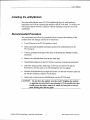
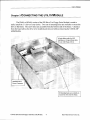
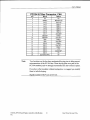
CMIO}.ZIP
IDE and FloppyController
utilitvModule
U
User'sManual
HardwareRevision1.0
M*o
RealTime DevicesUSA,Inc.
'Accessing
the Analog World$
Publicafion No. CMl 02-ZIP | 1.7.2001
ISO9001 and AS9100 Certified
CMlO2-ZIP
IDE and Floppy utilityModule
User'sManual
REAL TIME DBVICESUSA,INC.
PO Box 906
StateCollege,PA 16804-0906
USA
(814)234-8087
Phone:
FAX: (814)234-5218
E-Mail
[email protected]
techsupport@rtdusa.
com
Website
www.rtdusa.com
Notice: We have attemptedto verify all information in this manual is correct as
of the publication date. Information in this manual may changewithout prior
notice from Real Time DevicesUSA.
Published by
Real Time Devices USA. Inc.
P.O.Box 906
StateCollege,PA 16804-0906USA
Copynght 1999 by Real Time Devices USA, Inc.
All rights reserved
Printed in U.S.A.
PCD(T, PC/AT are registeredtrademarksof IBM Corporation.
PCllO is a registeredtrademark of PC/104 Consortium.
The Real Time Devices Logo is a registeredtrademark of Real Time Devices.
utilityModule is a trademark of Real Time Devices.
All other trademarksappearingin this document are the property of their respectiveowners.
Tableof Gontents
CHAPTER I
CHAPTER
2
rNrRoDUCrroN..........
...................1
CoNFIGURINGTHE UTILITYI\{ODULE
INSTALLTNG
CHAPTER 3
coNNEcrrNGTrrEurrLrryMoDULE......
.........................e
FTNDINGPIN I oF
PC/104Bus ColrNEcrons,
CNI eNoCN4
CHAPTER 4
.......................12
usrNc rHE urrLrryMoDULE..................
..........................18
por,rcy ANDwARR8Nry............
RETTJRN
......................21
PowBnPnor
CHAPTER 5
User's Manual
Ghapter1 INTRODUGTION
This manual gives information on the CM102-ZW IDE Hard Drive and Floppy
Controller utilityModule. This module allows you to connectstandardIDE hard
drives, ZIP-DrivesrM,CD-ROM's and floppy drives to your PCllO4 system. This
manual was written primarily for use of the CML}2-ZW with the RTD family of
IDAN or HiDAN systems. A power connectoris availableto connectto the IDE
drive or floppy drive.
CM.lOz-ZlP IDE and Floppy Controller utilityModule
The CMl02-ZW utilityModule was designedto provide an IDE drive and floppy
drive controller in thePCll}4 stack to supportthe Real Time Devices family of
IDAN / HiDAN svstems.
CMI}Z-ZIP IDE and Floppy controller utilifyModulel
RealTime DevicesUSA. Inc.
Features
The following aremajor featuresof the CM|}T-ZE utilityModule.
IDE Controller and Drive
o JumperEnablelDisable
mode-- Allows disablingthe controller
whennot connected
to IDE drives.
o Jumperselectionof primaryor secondary
IDE interfacein bus
mode
o Primary-- IDE Interfaceat 1F0-1F7h,
3F6-3F7h,
Intemrpt14
-- IDE Interfaceat 170-I77h,376-377h.
o Secondary
Intemrpt15
FloppyController
o Supports
two 360KB, 1.2MB,7201<8
or 1.44MBdrives
o
JumperEnableiDisablemode -- Allows disabling the controller
when not connectedto floppy drives.
o
Jumper selectionto configure the Floppy interface as primary
or secondarymode.
CMl02-ZlP IDE and Floppy conholler utilityModule
Real Time Devices USA, Inc.
User'sManual
Connecfors
providedare:
Connectors
. CNl PCllO4Bus(XT)
. CN2:Reserved
. CN3:IDE cableconnector
. CN4:PCll}4 Bus(AT)
. CN5: Floppycableconnector
. TBI'. +5, rT2 Vdc, andgroundVO terminalblock
CMIO2-ZIP IDE and Floppy controller utilityModule
Real Time Devices USA. Inc.
General Specifications
.
.
.
.
.
.
.
.
Dimensions:
3.575x3.775x 0.6" (90.2x95.9x15mm)
(mass):
3.0 ounces(85 grams)
Weight
6-layerPCB
Operatingconditions:(not includingdrive)
-40 - +85 degreesC
temperature:
non-condensing
relativehumidity:0 - 95o/o,
-55
+85 degreesC
temperature:
to
Storage
PowerRequirements:
I25 mA @ 5 Vdc (typical)
CMl02-ZlP IDE and Floppy controller utilityModule
4
Real Time DevicesUSA, Inc.
User'sManual
2 coNFIGURINGTHEUTILITYMOOUIe
Ghapter
The following sectionscontain information on configuring the utilityModule.
CMI0Z-ZIP IDE and Floppy controller utilityModule
5
Real Time Devices USA, Inc.
JumpersJPl
The utilityModule is configured by positioning jumpers. Jumpersare labeled on the board as r?JPrr
followed by a number.
The figure below showsjumper locations.
JPI
IDE Enable
?+<-Roppy
IDEMode
FloppyDrive Enable
Mode
JPl Seffings
l-2 IDE enable(default)
3-4IDEdisable
5-6 IDE primarycontroller
7-8 IDE secondary
controller (default)
9-10Floppyenable
II-12 Floppydisable
13-14Floppyprimary (default)
15-16Floppysecondary
CMl02-ZlP IDE and Floppy controller utilityModule
Real Time DevicesUSA. Inc.
User's Manual
lnstalli ng the utilityModule
Since the utilityModule usesa PC|I}4 stackthroughbus, the only hardware
installationyou will do is placing the module to the PCll}4 stack.To do this, you
will connect the PC/l04 bus connectorwith the matchins connectorof a RTD
cpuModule.
RecommendedProcedure
We recommendyou follow the procedurebelow to ensurethat stacking of the
modules does not damageconnectorsor electronics.
o
Turn off power to the PC/104 systemor stack.
o
Select and install standoffsto properly position the utilityModule on the
PCll04 stack.
o
Touch a groundedmetal part of the stack to dischargeany buildup of static
electricity.
o
Remove the utilityModule from its anti-static bag.
o
Check that keying pins in the PC/104 bus connectorare properly positioned.
o
Check the stacking order: make sure an XT bus card will not be placed
between two AT bus cards,or it will intemrpt the AT bus signals.
o
Hold the utilityModule by its edgesand orient it so the bus connectorpins line
up with the matching connectoron the stack.
o
Gently and evenlypressthe utilityModule onto the PC/104stack.
CAUTION: Do not force the module onto the stack! Wiggting the module
or applying too much force may damage it.If the module does not
readily press into place, remove it, check for bent pins or out-ofplace keying pins, and try again.
CMl}2-ZlP IDE and Floppy controller utilityModule
Real Time Devices USA. Inc.
CMI02-ZIP IDE and Floppy controller utilityModule
RealTime DevicesUSA, Inc.
User'sManual
THEUTILITYMOOUIE
Ghapter
3 GoNNECTING
The IDAN or HiDAN version of the ZIP-DriverMor Floppy Drive Module is madeto
easily install the 3 % drive of your choice. Two setsof mounting holes are available to securethe
drive to the frame. The screw holes are accessiblefrom the bottom side of the frame. Clearance
from the board allows the drive to be installed and removed without removins the CM102-ZIP
utilitvModule.
40-pinribboncablefor IDE
interfacesor 34-pinribboncable
for usewith FloppyDrives
!&i ,
,:
t
tr
*i:
tr'E{.)
8 Mounting holes are available to
securethe drive into the frame.
CM|D2-ZLPIDE andFloppycontrollerutilityModule
RealTimeDevicesUSA,Inc.
Connecting the utility cables
The following sectionsdescribeconnectorsof the utilityModule.
The figure below showsconnectorlocations.
/Ms,, Fg
nar I
alool
glool
I r_rl
f"-rr-r--E
*r.r-o. *'0r.,*rr ilFl LLj4lS\
CIE-rl
gL-
#1331
cr5Rrn
lool
133l
133l
CN3 - IDE Drive
Connector
TB1 - Power
TerminalBlock
f*l
rl o
ql
!
CN4 - AT Bus
CN2 - Reserved
tI t st
|
tl
Cl!|---'l
JPl - Jumper
Settings
*
iT
Ul
EIz!u,, o
r r l--'l
ls_r#
*LsJ{f;j"
Tf
CNI - XT Bus
r_-----il
nRlo
*t
$abbourfltltu sofll3
cE
nzEll-lol,c
Rzrr
E |lgl
"i"-rilm
CN5 - Floppy
Drive Connector
FZ--
nsElltl
n
l"
3l----l3
.'rr
I o{1
crf
nffi
rE
O
o
c2sn
*$
ConnectorDescriptions
Connectors
Function
Connector
CNI
PC/104XT Bus
PCllO4AT Bus
Factorvuseonlv
CN4
CN2
CN3
CN5
TBI & TB2
Size
64pn
40 pin
IDE
Floppy
40 oins
+5.+12Vdc.& Gnd
3 terminals
CMI02-ZIP IDE and Floppy controller utilityModule
l0
34 oins
Real Time DevicesUSA, Inc.
User'sManual
Finding Pin 1 of Connecfors
A white areasilk-screenedon the PC board indicatesthe pin 1 end of connectors.
A squaresolder pad visible on the bottom of the PC board also indicates it.
Pleasemake certain you have correctly identified pin 1 of a connectorbefore you
connectto it and attempt to use the utilityModule.
PIN ASSIGNMENT
4
CMLI2-ZIP IDE andFloppycontrollerutilityModule
Inc.
ll
RealTimeDevicesUSA.
PC/104Bus Connectors,CNl and CN4
CN1 carriesXT bus
Connectors
CNI andCN2providePC/104busconnections.
signals,andCN2 carriesadditionalsignalsfor the AT bus.The signalson CNl
andCN2 conformto theIEEE P966standardfor the PC/104bus.
pinouts:
Thefollowingtableslist theconnector
PCl104XT Bus Gonnector.GN1
Pin
I
Row A
Row B
IOCHCHK*
OV
RESETDRV
+5V
IRO9
-5V
DRO2
2
3
4
5
6
SD7
SD6
SD5
SD4
SD3
SD2
7
8
9
0
I
2
J
4
5
6
1
8
9
20
21
22
23
24
25
26
27
28
29
30
SDI
SDO
IOCHRDY
AEN
SA 9
SA 8
SA 7
SA 6
SA 5
SA 4
SA
SA 2
SA
SA 0
SA9
SA8
SA7
SA6
SA5
SA4
SA3
SA2
3t
32
a
J
SAl
SAO
OV
-t2v
ENDXFR*
+l2Y
(KEYINGPIN)
SMEMW*
SMEMR*
low*
IOR*
DACK3
DRO3
DACKI*
DROl
REFRESH
SYSCLK
IRQT
IRQ6
IRO5
IRQ4
IRQ3
DACK2*
TC
BALE
+5V
OSC
OV
OV
Note: Signalsmarked with (*) are active low
CMI02-ZIP IDE andFloppycontrollerutilityModule
t2
Real Time DevicesUSA, Inc.
IJser's Manual
PCl104AT Bus Gonnector,CN4
Pin
Row C
0
OV
SBHE*
LA23
LA22
I
2
a
J
4
LAzI
5
6
7
8
9
l0
LA2O
LAI9
LAl8
LAIT
MEMR*
MEMW*
SD8
SD9
SDIO
SDIl
SDI2
SD13
SD14
SD15
KEYING PIN)
ll
t2
l3
l4
l5
t6
t7
l8
t9
Note:
Row D
OV
MEMCSI6*
TOCSl6*
IROIO
IRO11
TRO12
IROI5
IROI4
DACKO*
DROO
DACK5*
DRO5
DACK6,I.
DRO6
DACKT*
DROT
+5V
MASTER*
OV
OV
Two locations on the bus have mechanicalkeying pins to help prevent
misconnectionof the PCll}4 bus. Thesekeying pins are a part of the
PC/104 standard,and we stronglyrecommend you leave them in place.
If you have other modules without keying pins, we suggestyou modiff
them to include keying.
Signalsmarked with (*) are active low.
CM|02-ZIP IDE and Floppy controller utilityModule
Inc.
l3
Real Time Devices USA.
IDE Drive, CN3
CN3 is a 40-pin DIL connectorused for connectingthe IDE drive. The pinout of
this connectoris shown below.
IDE Drive Connector.CN3
Pin
I
2
-)
4
5
6
7
8
9
l0
l1
t2
13
t4
l5
16
17
18
19
20
2l
22
23
24
25
26
27
28
29
30
31
32
33
34
35
36
)t
38
39
40
Sienal
Function
in/out
RESET*
out
GND
ResetHD
Ground sienal
HD data 7
HD data 8
HD data 6
HD data 9
HD data 5
HD data 10
HD data 4
HD data I I
HD data 3
HD data 12
HD data2
HD data 13
HD data I
HD data 14
HD data 0
HD data 15
Ground sisanl
Not Connected
Address Enable
Grotrnd sisanl
IOW*
GND
IOR*
VO Write
Groundsisanl
VO Read
GND
Ground sisnal
VO Channel Ready
Bus Address Latch Enable
Not Connected
Ground sisnal
Interrupt Request
GND
HD7
HD8
HD6
HD9
HD5
HDlO
HD4
HDI 1
HD3
HD12
HDz
HD13
HDI
HDI4
HDO
HDI5
GND
N/C
AEN
IOCHRDY
BALE
N/C
GND
IRO
IOCS16*
AI
GND
16bit transfer
Address1
inlout
inlout
inlout
inlout
inlout
ir/out
itt/out
inlout
inlout
inlout
inlout
in/out
in/out
inlout
in/out
irlout
out
out
out
m
out
ln
ln
out
Ground sisnal
Address0
Address2
AO
A2
HCSO*
HCSI*
HD Select0
HD Select 1
HDD activifv LED (Ground sisnal
LED
GND
out
out
out
0uI
in
Note:Signalsmarkedwith (*) areactivelow
CM|}2-ZIP IDE and Floppy controller utilityModule
14
Real Time Devices USA. Inc.
lJser'sManual
Floppy Drive, CN5
CN5 is a34-pinDIL connectorthat provides the standardsignalsto connect one
or two floppy disk drives. The pinout of this connectoris shown below.
FlonnvDrive Connector.CN5
Pin
Sienal
2
RWC*
N/C
4
6
8
10
t2
t4
16
l8
20
22
24
26
28
30
32
34
ODD
PINS
N/C
INDEX*
MOTEN1*
DRVSELI*
DRVSEL2*
MOTEN2*
Function
write orecornoensation
Not Connected
Not Connected
index pulse
In/out
out
motor I enable
drive select 1
drive select I
motor 2 enable
steo direction
out
out
out
out
steonulse
out
out
out
m
DIRECTION*
STEP*
WRDATA*
WREN*
TRACKO*
WRPROT*
RDDATA*
HEADSEL*
DSKCHG*
GND
write data
write enable
track 0 sisnal
write nrotect
read data
head select
disk chanse
Groundsignal
ln
our
ln
m
out
m
Note: Signalsmarked with (*) are active low
CMI}Z-ZIP IDE and Floppy controller utilityModule
Inc.
15
Real Time DevicesUSA.
Auxiliary Power TBl
WARNING! If you improperly connectpower, the module will almost certainlybe destroyed.
Pleaseverify power connectionsto the module before applyng power.
Thepowersupplyis conveyedto theutilityModulethroughthe PC/l04 bus(CNl andCN4).
TheutilityModuleonly uses+5 VDC andground. +12 VDC maybe requiredfor the Drive..
NOTE
-5 VDC, +12VDC and-12VDC voltagesarenot usedby themodule,but
arecomectedto thePC/104busconnectors.
CNl andCN4.
TBI is a power connectorand is usedto connectpower to the drive. The terminals are
marked clearly with the appropriatesignal for easypower connections. Use a flat blade
screwdriverto tighten the screw againstthe insertedwire.
Terminalblock ConnectorTB1
Pin
TB1-1
TB1-2
TBI-3
Sisnal
Function
+12VoltsDC
Ground
+5 Volts DC
+t2v
GND
+5V
CMI02-ZIP IDE andFloppycontrollerutilityModule
t6
Real Time Devices USA, Inc.
User's Manual
CMI02-ZIP IDE and Floppy controller utilityModule
Inc.
l7
Real Time DevicesUSA,
4 Uslttc THEUTILITYMoDULE
chapter
IDE Drive
The CMl02-ZW provides an IDE interface standardIDE Drive. This drive canbe
set up as the primary or the secondarydrive (you must be sure that your CPU
BIOS supportsboth primary and secondarydrives).
Since the CMl02-ZIP provides the IDE decodingon-boardyou must be sureto
disable any other IDE controllers that might be presentin your systemor set one
of the controllers to Secondary to prevent controller chip interface conflicts.
You mayneed to run the bios setupprogram for your cpuModule or computer to
configure the correct hard drive t1pe.
Floppy Drive
The CMl02-ZW provides a Floppy Drive interface.This drive can be set up as the
primary or the secondary(you must be sure that your CPU BIOS supportsboth
primary and secondarydrives).
Since the CM102-ZIP provides the Floppy decodingon-board you must be sure to
disable any other Floppy controllers that might be in your systemor set one of the
controllers to Seconda4yto prevent controller chip interface conflicts.
You may needto run the bios setupprogram for your cpuModule or computer to
configure the correct Floppy drive type.
CMl02-ZlP IDE and Floppy controller utilityModule
l8
Real Time Devices USA, Inc.
lJser's Manual
PowerP rotectionCircuitry
To reducethe risk of damagedue to power-supplyproblems, the utilityModule
includes severalprotective components.
Module Power-Supply Protection
TheutilityModuleincludescomponents
to helppreventdamagedueto problems
+5
power
with the VDC
supplyfrom thePC|I}4 busor power-supplyconnector.
Protectionis providedfor:
. Over-current
. Reversedpolarity
. Excessive
voltage
This protectionis only for the utilityModule,andwill not protectotherdevicesin
aPCl104stack.
Theprotectivefuseis replaceable
andis availablefrom electronicssuppliers.Its
descriptionandpartnumberare:
LittelfuseNano2SMF 1.0amp,R451-001
Caution: Replacefuses only with parts of identical current and voltage rating.
CMI0}-ZIP IDE andFloppycontrollerutilityModule
Inc.
l9
RealTimeDevicesUSA,
CMI02-ZIP IDE and Floppy controller utilityModule
Real Time Devices USA, Inc.
User's Manual
Ghapter
s RETURNPOLICYANDWARRENTY
ReturnPolicy
If the utilityModulerequiresrepair,you mayreturnit to us by following the
procedure
listedbelow:
Caution:
Failure to follow this return procedure will almost always delay repair!
Pleasehelp us expediteyour repair by following this procedure.
1) Read the limited warranty which follows.
2) Contact the factory and requesta ReturnedMerchandiseAuthorization (RMA)
number.
3) On a sheetof paper,write the name,phone number, and fax number of a
technically-competentpersonwho can answerquestionsaboutthe problem.
4) On the paper,write a detaileddescription of the problem with the product.
Answer the following questions:
.
.
.
.
.
.
Did the product ever work in your application?
What other deviceswere connectedto the product?
How was power suppliedto the product?
What featuresdid and did not work?
What was being donewhen the product failed?
What were environmentalconditions when the product failed?
5) Indicate the method we should use to ship the product back to you.
.
.
.
We will return warranty repairsby UPS Ground at our expense.
Warranty repairs may be returnedby a faster serviceat your expense.
Non-warranty repairswill be returnedby UPS Ground or the method you
select,and will be billed to you.
6) Clearly specify the addressto which we should retum the product when
repaired.
7) Enclosethe paper with the product being returned.
8) Carefully packagethe product to be returned using anti-static packaging! We
will not be responsiblefor productsdamagedin transit for repair.
7) Write the RMA number on the outside of the package.
CMI02-ZIP IDE and Floppy controller utilityModule
Inc.
2l
Real Time Devices USA,
Limited Warranty
RealTime DevicesUSA, Inc. warrantsthe hardwareandsoftwareproductsit
manufactures
andproducesto be freefrom defectsin materialsandworkmanshipfor one
yearfollowing the dateof shipmentfrom REAL TIME DEVICESUSA. This warrantyis
limited to the originalpurchaserof productandis not transferable.
Duringthe one-yearwarrantyperiod,REAL TIME DEVICESUSA will repairor replace,
at its option,anydefectiveproductsor partsat no additionalcharge,providedthat the
productis retumed,shippingprepaid,to REAL TIME DEVICESUSA. All replacedparts
andproductsbecomethe propertyof REAL TIME DEVICESUSA. Beforereturningany
productfor repair,customersarerequiredto contactthe factoryfor anRMA number.
THIS LIMITED WARRANTY DOESNOT EXTEND TO ANY PRODUCTSWHICH
HAVE BEEN DAMAGED AS A RESULTOF ACCIDENT,MISUSE,ABUSE (suchas:
useof incorrectinput voltages,improperor insufficientventilation,failureto follow the
operatinginstructionsthat areprovidedby REAL TIME DEVICES,"actsof God" or
othercontingencies
beyondthe controlof REAL TIME DEVICES),OR AS A RESULT
OF SERVICEOR MODIFICATIONBY ANYONE OTHERTHAN REAL TIME
DEVICES.EXCEPTAS EXPRESSLYSETFORTHABOVE,NO OTHER
WARRANTIESARE EXPRESSEDOR IMPLIED, INCLUDING,BUT NOT LIMITED
TO, ANY IMPLIED WARRANTIESOF MERCHANTABILITY AND FITNESSFOR
A PARTICULARPURPOSE,AND REAL TIME DEVICESEXPRESSLYDISCLAIMS
ALL WARRANTIESNOT STATEDHEREIN.ALL IMPLIED WARRANTIES,
INCLUDING IMPLIED WARRANTIESFORMECHANTABILITY AND FITNESS
FORA PARTICIILAR PURPOSE,ARE LIMITED TO THE DURATION OF THIS
WARRANTY. IN THE EVENT THE PRODUCTIS NOT FREEFROM DEFECTSAS
WARRANTEDABOVE, THE PURCHASER'SSOLEREMEDY SHALL BE REPAIR
OR REPLACEMENTAS PROVIDEDABOVE. TINDERNO CIRCUMSTANCES
WILL REAL TIME DEVICESBE LIABLE TO THE PURCHASEROR ANY USER
FORANY DAMAGES,INCLUDING ANY INCIDENTAL OR CONSEQUENTIAL
DAMAGES,EXPENSES,LOST PROFITS,LOST SAVINGS,OR OTHERDAMAGES
ARISING OUT OF THE USE OR INABILITY TO USE THE PRODUCT.
SOMESTATESDO NOT ALLOW THE EXCLUSIONOR LIMITATION OF
INCIDENTAL OR CONSEQUENTIALDAMAGES FOR CONSUMERPRODUCTS,
AND SOMESTATESDO NOT ALLOW LIMITATIONS ON HOW LONG AN
IMPLIED WARRANTY LASTS, SO THE ABOVE LIMITATIONS OR EXCLUSIONS
MAY NOT APPLY TO YOU.
THIS WARRANTY GIVESYOU SPECIFICLEGAL RIGHTS,AND YOU MAY
ALSO HAVE OTHERRIGHTSWHICH VARY FROM STATETO STATE.
CMII2-ZIP IDE and Floppy controller utilityModule
Real Time DevicesUSA. Inc.