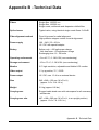
1
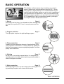
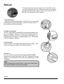
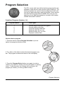
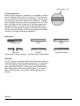
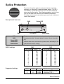
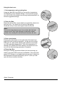
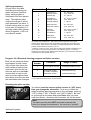
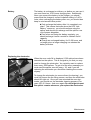
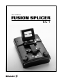
User´s Manual
FUSION SPLICER
63TB011
EC 1
1
Table of Contents
Safety Information ............................................................. 3
Description of EC1 ............................................................ 4
BASIC OPERATION ......................................................... 5
Set-up ....................................................................... 6
Program Selection .................................................... 7
Fiber Preparation ...................................................... 8
Splicing ................................................................... 10
Splice Protection ..................................................... 13
ADVANCED FUNCTIONS .............................................. 15
Splicing Programs ................................................... 15
Editing Splicing Programs ....................................... 17
User Options ........................................................... 18
Setting User Options............................................... 19
Maintenance .................................................................... 20
Accessories and Ordering ............................................... 22
Appendices
A - Error Codes ....................................................... 24
B - Technical Data ................................................... 25
Index................................................................................ 26
Service Locations ............................................................ 27
Table of Contents
2
Safety Information
The EC1 Fusion Splicer is part of the Ericsson family of
compact fusion splicers designed to meet all the needs
associated with repairs and installations of fiber optic cable in
trunk, local, data or cable-TV networks. It is distinguished by
its simplicity of operation and portability, offering efficient
splicing at low-cost.
In line with its user-friendliness, the EC1 comes with six predefined splicing programs that handle the most common
types of single fiber splicing. In the section on Basic Operation you can read about these programs, as well as follow
step-by-step through the use of the splicer. In addition, the
EC1 allows you to design your own splicer programs. These
are discussed as part of the section on Advanced Functions,
along with details about user options.
In spite of EC1’s ease of use, though, you should always keep
in mind several pieces of safety and maintenance information.
Operational
Precautions
Maintenance
Precautions
Transport and Storage
Precautions
lDo not use the splicer in
locations where there is a risk
of explosion.
lNever touch the electrodes
when the splicer is on.
lNever open the splicer or
the power supply during
operation.
lNever loosen any screws
except those mentioned in
this manual, since you
may harm important adjustments.
lNever use hard objects to
clean the V-grooves or electrodes. Use the supplied
brush, or in the case of the Vgrooves, isopropyl alcohol
and cotton swabs.
lNever use acetone for
cleaning any part of the
splicer.
lKeep the splicer clean and
dry.
lNever leave your splicer in
direct sunlight or in places
where it might be exposed to
excessive heat (such as in
vehicles parked in the sun).
lAlways transport the splicer
in its carrying case to avoid
damage to its precision parts.
lKeep the humidity to a
minimum where the splicer is
stored. The humidity must
not exceed 98%.
lClose the safety shield
during transport.
!
Safety Information
3
Description of EC1
EC1 is delivered with:
lFiber holders (for single fibers, 125/250 µm)
lSpare pair of electrodes
lCleaning tools (two brushes and one pair of tweezers)
lUser’s manual
lCarrying case
Monitor
Adjustable high resolution
LCD monitor.
Reference line switch
Turns reference lines on
and off.
Power connection
(backside)
Connection for
external power
supply or battery.
Video output
(beneath screen)
Attachment for an external
monitor.
Heat oven
Plug-in unit for standard
heat-shrink sleeves.
Plug
(beneath screen)
Plug for attaching
external 12 V DC
devices.
Safety shield
For protection during the
splicing sequence.
Screen contrast
adjustor
Adjusts the light
intensity of the
background.
Electrodes
Replaceable electrodes are
located underneath safety
shield.
Fiber holder clamps
For fixing the fiber holders
to the splicer.
Dials
Control fiber
movement, as
well as, program
and parameter
setting.
Display
Displays splicing program
numbers, parameters and
error codes.
Program select button
Used for selecting splicing
programs.
Edit button
Used during parameter
editing and user option
setting to enter information
into the splicer.
Description of EC1
4
Electrode warning lamp
Indicates unstable arc or
worn electrodes when
illuminated.
Splice button
Starts the splicing
sequence.
Battery warning lamp
Indicates low battery
voltage when illuminated.
On/Off button
Turns unit on and off. Also
serves as an “escape key”
to abort other operations.
BASIC OPERATION
This chapter outlines step-by-step everything you need to
know to make clean, low-loss splices using the EC1. Since
every splicer is slightly different, it is recommended that you
read through this chapter before you set to work, regardless of
your previous level of experience. Once you are familiar with
the splicer’s basic operation, you can learn how to personalize
EC1’s capabilities to suit your particular needs by looking in
the chapter entitled “Advanced Functions.”
1. Set-up
Page 6
Particularly the first time, it is advisable to follow through stepby-step how to get the EC1 from its carrying case and into
use.
2. Program selection
Page 7
The right splice requires the right splicing program.
3. Fiber preparation
Page 8
Possibly the most important element of good splicing is correct preparation of the fibers. Carefully follow the guidelines
listed on these pages concerning stripping lengths, end face
quality and cleanliness.
4. Splicing
Page 10
As the EC1 is an entirely manual splicer it is necessary to
carefully position the fibers before splicing and afterwards to
check for bulges and waists.
5. Splice protection
Page 13
Assuming all goes well, one can wrap up the splicing process
by protecting the splice with a heat-shrink sleeve.
BASIC OPERATION
5
Set-up
The following steps show you how to set up the EC1 when
you arrive at a new work site. Please take note of the safety
tips and specifications to ensure that you are making use of
the EC1 in a safe and efficient manner.
1. Out of the box...
...and onto a level working space. Lift the EC1 out of its metal
carrying case by firmly placing your hands on both sides of
the machine and lifting upwards.
2. Power connection
The EC1 can either be connected to the external power supply or to a battery. Check to ensure that the power supply is
rated at 100-240 V, 50-60 Hz. In the case of the battery, it is
important that the battery is charged before use. The battery
is NOT charged on delivery.
3. Lift monitor
Lift the monitor to an angle appropriate to easy viewing. The
monitor will snap into place at the desired angle.
4. Turn on
To turn on the EC4 you press the button marked On/Off
located on the top of the splicer until “EC1” appears in the red
display. Once powered up, the motor working positions will be
calibrated.
Note:
Before pressing the power button, remove any fibers possibly left in the splicer from previous usage.
Set-up
6
Program Selection
The EC1 comes with 6 pre-defined splicing programs that are
intended to deal with the most common types of splicing. The
following explains the content of these programs in brief, and
how you go about selecting a splicing program. More information about splicing programs and details as to how you can
specify your own splicing programs is covered in the chapter
entitled “Advanced Functions.”
Predefined Programs (Numbers 1-6)
Program Number
1
2
3
4
5
6
Fiber Types
General single mode fiber and pigtails
General single mode fiber
Concentric single mode fiber
Multimode fiber 50 µm core
Multimode fiber 62.5 µm core
Dispersion shifted fiber
How to select a program
1. Press the button marked Program Selection to put the
splicer into program selection mode.
2. Turn either of the dials to select the desired program number. The program numbers are shown in the red display.
3. Press the Program Select button once again in order to
confirm your selection, thereby returning the splicer to splicing
mode. If after this point you change your mind as to the
program you desire, you must go back to Step 1.
Program Selection
7
Fiber Preparation
Fiber preparation is possibly the most critical operation in
splicing, so it is particularly important to carefully observe the
information regarding this procedure. The following leads you
through step-by-step, but it is also important to keep in mind
several general ingredients to low-loss splices:
lMinimal core eccentricity
lPerpendicular cleave surfaces
lCleanliness every step of the way
1. Heat-shrink sleeve
It is an easy, but ultimately very frustrating, step to forget, so
be sure to place a heat-shrinkable protection sleeve on one of
the fibers before stripping.
2. Fiber holders
Put the fibers into the correct type of fiber holders (see section
on cleave lengths, p.9) so that 25-35 mm of fiber sticks out.
Note also that, in order to set the holders into the splicer, you
must observe their left and right handedness.
3. Stripping
Strip the protruding lengths of fiber with an appropriate stripping tool. If using an electrical device, be sure to look over its
instructions before stripping.
4. Cleaning
Clean the bare fibers with a tissue or a pair of cotton swabs
soaked in alcohol. It is important that from this point on you
are very careful with the fibers to ensure that they do not
become dirty again (such as by laying them down on a dusty
working surface, or even waving them around in the air). Also
check at this point that the V-grooves are clean, and if not,
wipe them down with the provided brush or a cotton swab
dipped in alcohol.
5. Cleaving
Cleave the fibers with a high quality cleaving tool, so that the
end faces are free of tangs and chips (see ex., p. 11) and at
an angle no greater than 1-2%. In addition, double-check that
you are achieving the correct cleave lengths for your type of
fiber.
Fiber Preparation
8
Cleave lengths
Primary Coating
Stop
3
10
Secondary Coating
9
When splicing fibers with only
primary coating, use the
fiber holders marked 125/250
µm, and strip and cleave
such that approximately 13
mm of fiber extends from the
holder (3 mm coated, 10 mm
uncoated).
13
When splicing fibers with
tight secondary coating,
use the fiber holders marked
125/900 µm, and strip and
cleave such that there is
approximately 22 mm of fiber
exposed. As with single
fibers 13 mm of fiber should
extend beyond the edge of
the holder (the other 9 mm of
bare fiber lying within the
fiber holder).
Additionally, one should avoid
pressing the end of the secondary coating against the
stop (located along the
groove running the length of
the fiber holder: see picture)
since this may cause bad
alignment. Ideally the distance between the stop and
the end of the coating is 0.5
mm.
Measuring gauge
To check the stripping length
it is convenient to use a
measuring gauge. Proceed
as follows:
1. Place the fiber in the fiber
holder.
2. Place the holder on the
measuring gauge.
3. Position the fiber so that it
extends to the edge of the
gauge, thus achieving the
correct length.
Fiber Preparation
9
Splicing
As the EC1 is a manual splicer, splicing quality partially depends on the skill of the person who runs it. There is no
question that the longer you use the EC1, the more your
ability to perfectly line up the fibers will improve. Regardless
of your proficiency at splicing, however, there are several
points you must always observe:
lThe EC1 only allows you to align fibers based
on their cladding, so it is essential to use fibers
with good core concentricity.
lEnsure that the fibers do not suffer from fiber curl,
since curled fibers will not lie flat in the V-grooves.
lAnd once again, cleanliness. At this stage it is
particularly critical to take note of the V-grooves, for if
they are dirty the fibers will not line up properly.
1. Place the fibers
Open the safety shield and place the fiber holders onto the
racks on top of the splicer so that the fibers lie along the Vgrooves without colliding or overlapping.
Note:
Since you should not slide the fibers along the V-grooves,
the ideal procedure is to position the fibers over the Vgrooves, keeping the fiber holders at an angle, and then to
tilt the fiber holders down into place, letting the fibers fall
into the V-grooves.
1
2
2. Clamp fiber holders
Lock the fibers into place by pushing up the clamps so that
they snap down onto the fiber holders. Once the fiber holders
are secure, you can reclose the safety shield.
(Cont., p. 11)
Splicing
10
(Cont. from p. 10)
3. Align the fibers
Once you have reclosed the safety shield, you should be able
to see the fibers in the screen. It is now time to inspect the
fibers once again for dust and to review the cleave (see “Note”
below). To align the fibers, you use the dials located on either
side of the EC1--each dial moves its corresponding fiber. As
an aid, you can turn on the reference lines with the switch
located just below the screen. You want to get the fibers as
close as possible without collision or overlap.
Note:
If you can see any dust on the fibers, or if the cleave is
excessively angled or includes tangs or chips, you should
remove the fibers from the machine and re-strip and recleave. It is also recommended to clean the V-grooves. It
sounds tedious, but the fact is that these defects will prevent the EC1 from giving a low-loss, high-strength splice.
Dust on fiber
Tang
Chip
Large cleave angle
4. Press “Splice”
When you are satisfied with the fibers’ alignment you can push
the button Splice. It is never a waste of time, though, to first
glance again at the displayed program number to reassure
yourself that the desired splice program will be run.
Note:
It may happen that the arc fails to start, possibly because the
electrodes are worn-out or dirty. When this occurs, the
display shows error code 02. By pressing Splice again, it is
possible to make a new attempt to start the arc. However,
after three failed attempts, the display will change to error
code 03, and it means that the electrodes must be cleaned
or changed. (See these instructions in “Maintenance,” p.
21).
(Cont., p. 12)
It is also possible that the electrodes do start, but that they
make a sizzling sound. In this case, the electrodes are dirty,
and you should run the electrode cleaning program,
Program 100. (Follow “Program Selection” instructions, p. 7).
Splicing
11
(Cont. from p. 10)
5. Check the splice
After the splice program is complete, it is advisable to make a
visual inspection of the splice on the screen. If all went well,
the outer diameter will be smooth and straight, and the white
line along the center of the fiber will be continuous. (Keep in
mind, though, that this line does not represent the core of the
fiber, but rather just the focus point of the light being shown
through the fiber, so you do not learn anything about core
alignment by looking at this image). If there are any anomalies (see examples below), then it will probably be necessary
to start all over again with fiber preparation.
Bad splices
Mis-alignment
Waist
Bulge
Ball ends
(Possibly arc current too high)
Bubble
(Possibly fiber contamination)
Incomplete fusion
Prefusion
The EC1 splicer is equipped with automatic prefusion which is
executed directly before the splicing sequence. It is possible
to set the program parameters so that the splicing program
stops right after prefusion. In this way you can examine the
fibers again before continuing with the splice. For more details, you should look in the section entitled “Setting User
Options.”
Splicing
12
Splice Protection
To protect the splice against mechanical stress and water
damage, you can apply a heat-shrinkable sleeve. The EC1
conveniently comes with a built-in heat oven that melts the
sleeve around the splice. The following explains, in brief, how
you use the heat oven, but for more detailed information,
including maintenance instructions, you must look in the heat
oven’s own manual.
Description of heat oven
SW2
SW1
SW2
Green LED
SW1
SW1
SW2
Green LED
Yellow LED
Start button
Yellow LED
Start button
Temperature dial. See table below for values. Set to 2 on delivery.
Operating time dial. See table below for values. Set to 2 on delivery.
Indicates heat oven is connected to a power source and ready for use.
Indicates heat oven is running.
Pushing the start button initiates the heat shrinking operation.
SW1
SW1/2 settings
SW2
Dial setting
Temp. (oC)
Dial setting
Time (sec)
0
1
2*
3
4
5
6
7
8
9
95
100
105
110
115
120
125
130
135
140
0
1
2*
3
4
5
6
7
8
9
45
60
75
90
105
120
135
150
165
180
* Setting on delivery
Suggested settings
* Setting on delivery
SW1
SW2
5
5
2-3
2-3
Fiber type Shrink tube type
Single
Single
Raychem SMOUV-1120-01
Sumitomo FPS-1
Splice Protection
13
Using the heat oven
1. Set temperature and operating time
Using the dials SW1 and SW2 you can set the temperature
and operating to the desired settings. On the previous page
you can find all of the details concerning these parameters, as
well as suggested settings.
2. Place the fiber
Place the spliced fiber surrounded by its protection sleeve into
the heat oven. You should try to keep the fiber gently
stretched until you have once again closed the the lid.
Note:
Do not let sharp objects come into contact with the heat
element since they might damage its specially treated
surface, thus raising the risk that shrink sleeves will stick.
3. Press start button
Pressing the start button on the right side of the heat oven
begins the heat shrinking operation. At this point the yellow
LED goes on, and emits a steady light while the oven heats
up to the operating temperature. Once this temperature is
reached, the yellow LED starts flashing and continues to do
so until the heat shrinking operation is complete.
4. Removing fiber
During the cooling period that follows the heat shrinking operation, the green LED comes on and flashes. Only when the
green LED changes to a steady light and you hear a beep has
the temperature dropped sufficiently (to 80 oC) that you can
open the lid and remove the fiber.
Splice Protection
14
ADVANCED FUNCTIONS
Splicing Programs
The EC1 has the capacity to store 17 different programs to
meet your various splicing needs. The first six of these programs, Programs 1-6, are pre-defined and cannot be
changed, and are intended to address the most common
splicing requirements. Programs 11-20, on the other hand,
are editable and offer you the possibility to define programs to
suit your particular needs. The following few pages treat the
splicing programs in greater depth and explain how you go
about defining your own programs. Program 100 is the electrode cleaning program, and is discussed in more detail on
page 16.
Splicing program structure
EC1’s splicing programs are structured according to five basic
phases, which themselves break down into several parameters. The following table outlines this structure.
Phase
What happens
Parameters
#
Prefuse
The fibers are pulled so that a specified
gap lies between the ends and then
cleaned.
Prefuse time
Prefuse current
Prefuse gap
1
2
3
Overlap
The fibers are slid inward and the arc is
lit. While the fibers melt, pressure
continues to push them together.
Overlap time
Overlap current
Overlap distance
4
5
6
Main fusion
The fibers are kept stationary while the
arc is lit.
Main fuse time
Main fuse current
7
8
Pull
During this optional phase, the fibers are
pulled slightly apart while the arc is still
lit.
Pull time
Pull current
Pull distance
9
10
11
Relax
During this optional phase, the arc
remains lit and the fibers stationary.
Relax time
Relax current
12
13
Programs 1-6
Though it is not possible to
change the parameter values
in Programs 1-6, it is possible
to read them by following the
adjacent instructions. To
understand the values, refer
to the table about splicing
parameters on the next page.
1
Press Program Select and turn the dials to choose a program.
The program numbers appear in the red display.
2
Press Edit and turn the dials to choose a parameter number.
3
4
Press Edit again to read the value of the selected parameter
in the red display.
Press Edit to select a new parameter number or On/Off to return
to splicing mode.
Splicing Programs
15
Splicing parameters
As you saw in the table
describing the splicing programs’ structure (previous
page), each program is
composed of thirteen parameters. The adjacent table
outlines the range of values
each parameter can have. It
is these values that you read
in the case of Programs 1-6
and can modify when personalizing Programs 11-20 to fit
your specific needs.
Parameter No.
Parameter
1
2
3
Prefuse time
Prefuse current
Prefuse gap
0.1 - 20.0 sec.
10.0 - 20.0 mA
10 - 100 µm
4
5
6
Overlap time
Overlap current
Overlap distance
0.1 - max 13.3 sec.*
10.0 - 20.0 mA
1 - 100 µm
7
8
Main fuse time
Main fuse current
0.1 - 20.0 sec.
10.0 - 20.0 mA
9
10
11
Pull time
Pull current
Pull distance
0.0 - max 13.3 sec.*¤
10.0 - 20.0 mA
1 - 100 µm
12
13
Relax time
Relax current
0.0 - 20.0 sec.¤
10.0 - 20.0 mA
Range of possible values
* The maximum settable values for overlap and pull time depend on the settings of
the overlap and pull distances. This is due to a fixed minimum motor speed,
whereby short distances give short times while long distances give longer times.
The maximum values shown in the table for overlap and pull time are valid when
overlap and pull distances are set to 100 µm.
¤
Selecting a value of 0.0 sec. in the case of pulling and relaxation implies that you
do not want to include these operations in your splicing program. To design a
splicing program that involves pulling and/or relaxation, you must set the relax and/
or pull time to a value greater than 0.0.
Program 100 (Electrode cleaning program and Splice counter)
Built into the electrode cleaning program is both a readonly counter that shows the
total number of splices that
have been done on the machine as well as a resettable
counter that is used to indicate how many splices have
been done since the last time
the electrodes were changed.
Parameter
Number
Parameter
1
Current splicer counter
000-999 (possible to reset)
2
Total splice counter
(in 1000’s of splices)*
Total splice counter
000-999 (read-only)
3
Range of values
000-999 (read-only)
* For example, if parameter 2 reads “004” and parameter 3 reads “279,” then a total
of 4,279 splices have been done on the machine.
Resetting the splice counter
You should reset the current splice counter to “000” every
time you change the electrodes. To do so you follow the
steps for editing splicing programs on the next page, entering
“100” in Step 2, “001” in Step 4, and “000” in Step 6. Be sure
to go through all the steps and press Enter after you have
reset the counter, otherwise the information will not be saved.
Note:
The splice counter does NOT reset itself automatically
when you change the electrodes. You must do it yourself.
Splicing Programs
16
Editing Splicing Programs
Here is how you can change parameters’ values in Programs 11-20
to design your own splicing programs. On delivery, Programs 11-16
are copies of Programs 1-6, so you can use them as a start point.
Program
Select
1. Press the Program Selection button.
select
PROGRAM
2. Turn one of the dials to select the program (11-20) you
want to personalize.
3. Press the Edit button to enter editing mode, signalled by
the illumination of the LED on the Edit button.
Note:
If a security code is set (see page 18), the display will start to flash, and
you can not proceed until you enter the code by turning one of the dials
to the correct number and pressing Edit again.
Edit
select
PARAMETER
4. Select a parameter to change by turning one of the dials
until its value appears in the display. As an aide, refer to the
“Splicing parameters” table on page 16.
5. Press the Edit button to register your choice of parameter.
In response the LED on the Edit button will start flashing, and
the current value of the parameter will appear in the display.
Edit
select
VALUE
6. Change the parameter value by turning one of the dials.
Edit
7. Press the Edit button to store the new value. At this point,
if you have more parameters to change you should follow the
dashed arrow back up to Step 4. If you are done with your
modifications to the program, you can go onto Step 8 and
leave editing mode.
On/Off
8. When you are entirely done modifying the program, return
to splicing mode by pressing the On/Off button.
Editing Splicing Programs
17
User Options
?
The EC1 also includes a set of user options that allow you to
further personalize the splicer to your particular working
situation. These options are described below, and the method
for setting them is outlined on the next page.
1 - Security code
The EC1 is equipped with an optional three-digit security code
which allows you to protect your settings and splicing programs
from being changed without your knowledge. The code functions as
follows: when the red display is flashing, the security code must be
given using one of the dials and then entered with the Edit button.
If the incorrect security code is given, then the requested operation
is aborted.
2 - Prefuse control
If the prefuse control is on, the program will halt after prefusion.
This allows you to check the fibers before main fusion. If you then
want to continue the spicing operation, press the Splice button. If
you want to abort the splice, press the On/Off button.
STOP
3 - Changed parameter indication
This option is to assist you while you edit splicing programs by
telling you whether a selected parameter has already been
changed. If the parameter has been changed, its default value will
be displayed along with two beeps followed by its current value.
4 - Low battery warning level
This allows you to specify the voltage level at which you want the
splicer to warn you that the battery is getting low.
ll l
lllll
z
l
l
ll
llllll
z
llll
lll
llll
z zz z
l
ll
lllllll
lll
ll
l
OFF
llll
llllll
lll
zzzz zz z z
zz z
lll
llll
l
RESET
User Options
18
5 - Stand-by time
When the EC1 is powered from a battery it goes into stand-by mode
(low power mode) after a certain time in order to save the battery
charge. This option allows you to specify this length of time before
the splicer goes into stand-by mode. To reactivate from stand-by
mode, you just press the On/Off button.
6 - Shut-off time
This is where you specify how long you want the splicer to sit in
stand-by mode before it shuts off automatically.
7 - Reset splicing programs
If this function is turned on, all editable splicing programs will revert
to their default values.
Setting User Options
User options ranges
When you want to set the
user options, refer to the
adjacent table and follow
step-by-step below.
Note:
Be sure to remove any fibers
possibly left in the splicer before
getting started.
On/Off
Option
Number
1
2
3
4
5
6
7
Option
Security code
Prefuse control
Changed parameter
indication
Battery warning
level
Stand-by time
Shut-off time
Reset splicing
programs
Range of values
Default
Settings
0 - 999
0/1 (Off/On)
0/1 (Off/On)
0
0
0
10.5 - 12.5 V
11.3
0.1 - 99.9 min.
0.1 - 99.9 min.
Performed when
set to 0
1.0
10.0
-
1. Press the On/Off and Edit buttons simultaneously until the
red display shows “001.” At this point you are in set-up mode.
Edit
Note:
If a security code is set (see page 18), the red display will start to flash,
and you can not proceed until you enter the code by turning one of the
dials to the correct number and pressing Edit again.
select
OPTION
2. Turn one of the dials to select the option (1-7) you want to
set.
3. Press the Edit button to enter your choice and have displayed the current setting for the selected option.
Edit
select
VALUE
4. Turn one of the dials until the new desired value for the
option appears in the red display.
Edit
5. Press the Edit button to store the selected value. Then, if
you have no more options to set, proceed on to Step 6. However, if you want to change other options, start once again
from Step 2 and choose a new option number.
On/Off
6. To exit from set-up mode and end your session setting user
options, press the On/Off button.
Setting User Options
19
Maintenance
To keep the EC1 splicer in tiptop shape, there are three areas
of general maintenance you should regularly attend to.
l Cleanliness
l Battery
l Electrodes
The splicer is equipped with error messages (see p. 24) that
will remind you about some of these tasks, but ideally you will
make maintenance a habitual part of your use of the EC1.
Cleanliness
It may be tiresome to be reminded once again how important
cleanliness is; nevertheless, this is also the easiest, and most
recurrent, task associated with maintenance of the EC1. The
following is a summary of the most dirt sensitive parts of the
machine.
Both the fiber holders and
the fiber holder fixtures
should be regularly cleaned
with the glass fiber brush or a
cotton swab dipped in alcohol. You should also keep
your eyes open for any damage to the fiber holders,
particularly around the
grooves.
If the V-grooves are dirty,
then it will be impossible to
line up the fibers properly, so
if you see a visible fiber offset
on the screen, it is probably
due to dirty V-grooves. You
can clean the V-grooves with
the glass fiber brush or a
cotton swab soaked in alcohol. You should NOT clean
them with compressed air nor
with petroleum products.
You should remove the
electrodes and clean them
with the fiber glass brush only
when error codes 02 or 03
are shown. Do NOT clean
the electrodes with a cotton
swab dipped in alcohol. For
instructions as to how you
remove and reinsert the
electrodes see the section on
electrode maintenance on p.
21. Once you have them
remounted, you should run
the electrode cleaning program (Program 100, see
below) 2-3 times.
Program 100 (Electrode Cleaning Program)
You should make running Program 100 part of your daily
routine with the EC1. In addition to running it at the beginning
of each work day, you should stop and initiate Program 100
after every 15-20 splices. It is also the best corrective measure if the electrodes make a sizzling sound while the arc is lit.
Maintenance
20
Battery
The battery is uncharged on delivery, so before you can use it,
you must count on 16-20 hours charging time. Additionally,
when you connect the battery to the charger, you should
ensure that the charger’s current limitation setting is 0.45 A.
Later, when recharging the battery after use, you should also
keep in mind several other points.
l Only recharge the battery after it is completely run
down. This means that even when the LED “Low
Battery” comes on, you should continue using the
splicer and should not recharge until the splicer runs
out of power altogether.
l Even when not using the battery regularly, you
should recharge it once a month to maintain its full
capacity.
l Charge an uncharged battery for 16-20 hours, and
no longer since a longer charging can shorten the
battery’s lifetime.
Replacing the electrodes
When the error code 04 is displayed, 1000 splices have been
executed on the splicer. This is a signal to you that you may
want to change the electrodes. You certainly want to replace
them every 2000 splices. To get rid of the error message you
must reset the splicer counter (see p. 16), and if you are
replacing the electrodes you should be resetting the counter
anyway.
To change the electrodes (or remove them for cleaning), you
must first loosen the the fixing screws, and then the electrodes
should lift right out. Once you have mounted the new electrodes, you should run the electrode cleaning program (Program 100) 2-3 times. And once again: Do not forget to reset
the splicer counter whenever you replace the electrodes.
Maintenance
21
Accessories and Ordering
To place an order you should have the ordering number ready
and direct yourself to an authorized Ericsson representative.
To find the representative in your home country look on the list
at the end of the manual.
EC1
Ordering number:
EC1
63ST003
The EC1 kit includes the splicer, fiber holders,
a spare electrode set, cleaning tools (two glass
fiber brushes and a pair of tweezers), and a
user’s manual. Everything is conveniently
packaged in a metal carrying case.
Battery and external power supply are NOT
included.
One of your options for powering the EC1 is to
use an external battery. The battery holds a
charge equivalent to approximately 100 splices.
Battery
Ordering number:
Battery
Battery charger, Europe
Battery charger, USA
Battery charger, UK
42ST029
10000278
10000276
10000277
It is also possible to power the EC1 with an
external power supply which gives an input of
100-240 V, 50-60 Hz.
Power supply
Ordering number:
Power supply/Battery charger
Power cord, Europe
Power cord, USA
Power cord, UK
42ST072
10000159
10000160
10000161
For lengthy operation with no access to a
power outlet, a 12 V car battery can also be
used as a power source.
Car battery cable
Ordering number:
Car battery cable
42ST052
Heat oven
Ordering number:
Heat oven
Accessories and Ordering
22
57ST001
The heat oven is used for crimping protection
sleeves. Heat shrinkable sleeves for both
ribbon and single fiber can be used with the
oven. Additionally the heat oven can be conveniently set into the top of the of the EC1
splicer.
Measuring gauge
Ordering number:
Measuring gauge
42SM006
Ericsson offers a high quality stripping tool
intended for single fibers.
Fiber stripping tool
Ordering number:
Fiber stripping tool
10000640
Fiber cleaver EFC-P24
Ordering number:
Fiber cleaver
The EFC-P24 fiber cleaver offers low angle
cleaves, as well as built-in stripping length
measurement.
10000707
Fiber holders
Ordering number:
125/250 µm, left
125/250 µm, right
125/900 µm, left
125/900 µm, right
42SM049
42SM050
42SM052
42SM051
Electrode
Ordering number:
Electrode
The measuring gauge provides a convenient
way to achieve correct cleaving and stripping
lengths when using strippers and cleavers
others than those recommended by Ericsson.
Two different types of fiber holders are available for the EC1 splicer. The 125/250 µm
holders are intended for regular single fiber.
The 125/900 µm holders are necessary when
splicing fiber with tight secondary coating.
It is necessary to periodically replace the
electrodes, and Ericsson offers them for sale.
Be sure to buy a pair.
53SM006
Notes:
Accessories and Ordering
23
Appendix A - Error Codes
When an error occurs or the EC1 wants to give you maintenance information, you will hear a beep and see an “E” followed by a two-digit code in the red display.
Error
Error code
Corrective measure
01
Safety shield open when trying to splice
Close safety shield
02
Electrodes found to be bad based on the
most recent splicing operation
Try Splice again. If this fails, clean
and/or change the electrodes
03
Three splice attempts in a row failed
Clean and/or change electrodes
04
Electrodes used for more than 1000 splices
Reset splicer counter, and, if
necessary replace electrodes
05
Fibers positioned so that requested
movement is impossible
Prepare fibers again
06
Low battery voltage
Recharging will soon be necessary
07
Empty battery
Recharge or change batteries
08
Incorrect security code given
Abort operation or try again
09
Bad operation/ Handling error
Contact your authorized
Ericsson service partner
11
Incorrect operation in RAM
Contact your authorized
Ericsson service partner
12
Incorrect operation in EPROM
Contact your authorized
Ericsson service partner
13
Unable to write to EPROM
Contact your authorized
Ericsson service partner
15
Pressure sensor failure
Contact your authorized
Ericsson service partner
21
Step-motor drivers initiated with out-of-limit
values
Contact your authorized
Ericsson service partner
22
PWM signals initiated with out-of-limit values
Contact your authorized
Ericsson service partner
23
Attempt to display “undisplayable” values
Contact your authorized
Ericsson service partner
24
EPROM address out of range
Contact your authorized
Ericsson service partner
Appendix A - Error Codes
24
Appendix B - Technical Data
Fibers
Single fiber 125/250 µm
Single fiber 125/900 µm
Single mode, multimode and dispersion-shifted fiber
Splice losses
Typical value, using identical single mode fibers: 0.04 dB
Fiber alignment method
Fixed V-grooves for radial alignment
High precision stepper motors for axial alignment
Power supply
100 - 240 V, 50 - 60 Hz
12 V DC with special adaptor
Battery
Splicer only: >100 splices per charge
with heat oven: >70 splices per charge
Recharging time: 16 - 20 hours
Operating environment
-5 to +40 oC, 0 - 98% RH (non-condensing)
Storage environment
-15 to +70 oC, 0 - 98% RH (non-condensing)
Monitor
3.2” high resolution, adjustable and tiltable LCD monitor
Video output
1 V p-p positive, 75 Ω/CCIR
Power output
12 V DC, max 1.3 A to an external device
Size
240 x 340 x 152 mm (W x D x H)
(approx. 9.5 x 13.4 x 6 in.)
Weight
3.9 kg (approx. 8.6 lbs.)
Carrying case
Rugged cabin-sized case with extra space for all necessary
accessories
Carrying case size
497 x 198 x 395 mm (W x D x H, in an upright position)
(approx. 19.6 x 7.8 x 15.6 in.)
Appendix B - Technical Data
25
Index
A
H
Alignment. See Fiber alignment
Arc
failure to start 11
Heat oven 4, 13, 14, 22
Heat-shrink sleeve 8, 13, 14
B
Battery 22, 25
charging 6, 21, 24
warning lamp 4, 18
C
Car battery cable 22
Carrying case 3, 25
Clamps 4, 10
Cleaning
electrodes 11, 20, 24
fiber holders 20
precautions 3
stripped fibers 8
V-grooves 8, 10, 20
Cleaving 8
cleave angle 8, 11
tool 23
D
Dials 4
Display 4
Dust 11
E
Edit button 4, 17
Electrode cleaning program. See
Splicing programs: Program
100
Electrodes 4, 23
cleaning 11, 20, 24
precautions 3
replacement 11, 21, 24
warning lamp 4
Error codes 11, 21, 24
External devices 4, 25
F
Fiber alignment 11, 25
Fiber curl 10
Fiber holders 8, 23
Fiber placement 10
Fiber preparation 8-9
Index
26
M
Main fusion phase 15
Maintenance 3, 20-21
Measuring gauge 9, 23
Modes
editing mode 17
program selection mode 7
set-up mode 19
splicing mode 7, 15
Monitor 4, 6, 25
O
Splice losses 25
Splice Protection 13
Splicing 10-12
bad splices 12
Splicing programs
create your own (11-20)
7, 16, 17
parameters 15, 16, 17, 18
predefined (1-6) 7, 15
Program 100 11, 16, 20, 21
resetting to default 18
structure 15
Stand-by time 18
Stripping 8
tool 23
SW1/2 13, 14
On/Off button 4, 6
Overlap phase 15
U
P
User Options 18
setting 19
Power supply
characteristics 6, 22, 25
connection 4, 6
Precautions 3
Prefusion 12, 15, 18
Program 100. See Splicing programs: Program 100
Program select button 4, 7
Programs 11-20. See Splicing
programs: create your own
Pull phase 15
R
Reference lines 4, 11
Relax phase 15
S
Safety 3
Safety shield 3, 4, 24
Screws 3, 21
Security code 17, 18, 19, 24
Service Locations 27
Set-up 6
Shut-off time 18
Splice button 4, 11
Splice counter 16, 21. See also
Splicing programs: Program
100
V
V-grooves 3. See also Cleaning: Vgrooves
Video output 4, 25
Viewing angle adjustor 4
Service Locations
Argentina
Reycom electrónica S.A.
Bernardo de Irigoyen 972
Piso 6°
1304 Buenos Aires
tel: (54-1) 307-2185
France
Phase-Optic S.A.
Z. A. de Vaubesnard
7 chemin de Vaubesnard
F-91410 Dourdan
tel: +33 1 64551200
Austria
Ericsson Austria A.G.
Pottendorferstrasse 25-27
A-1121 Vienna
tel: +43 1 811 000
Germany
Macrotron Systems
Ammerthalstrasse 7
D-85551 Kirchheim
tel: +49 8 945 111 283
Belgium
Phase-Optic S.A.
Z. A. de Vaubesnard
7 chemin de Vaubesnard
F-91410 Dourdan France
tel: +33 1 645512 00
Hong Kong
Comtec
Far East Reg Office
Rm. 607, Austin Tower, 22-26A
Austin Ave.
Tsim shatsui, Kowloon
tel: +852 23 112 263
Brazil
ASGA Microelectrónica S.A.
Rodovia Dr. Roberto Moreira
Km 4-CP 132
13140-000 Paulínia, SP
tel: 55 19 8442020
Canada
Amherst Fiber Optics
Brentwood Commons Two,
Suite 205
750 Old Hickory Blvd.
Brentwood, TN 37027 USA
tel: +1 (615) 376-4396
China
Wall International Group
Vantone Plaza, Room B1606
No. 2 Fu Cheng Men Wai St.
Beijing 100037
tel: 86 10 68579091
Czech Republic
HKE, spol. s.r.o.
Na Cikorce 3
CZ-143 00 Prague 4
tel: 420 2 402 6889
Denmark
Ericsson Components Dist.
Sluseholmen 8
DK-1790 Copenhagen V
tel: +45 33883101
Finland
Viikinkikaapeli Oy
Sierakiventie 8
SF-02780 Espoo
tel: +358 9 299 65 00
India
Subex Systems Ltd.
721, 7th Main
Mahalaxmi Layout
Bangalore – 560 086
tel: +91 80 3327581
Ericsson Comm. Pvt. Ltd.
The Great Eastern Plaza
2-A Bhikaji Cama Place
New Dehli 110 066
tel: +91 11 6180808
Indonesia
Ericsson Indonesia P.T.
Wasma Pondok Indah, 10th Fl.
JL Sultan Iskandar
Muda V. TA
Jakarta 12310
tel: 62 21 7693555
Italy
Advance Italia Srl
Via F. lli Cernuschi 22
I-22055 Merate (LC)
tel: +39 039 990 7612
Japan
Opto Science, Inc.
Naitocho Bldg 7F,
Naitocho 1 - Banchi
Shinjuku - Ku
Tokyo 160-0014
tel: +81 3 33561064
Malaysia
Communication Techn. Sdn Bhd
No 6, Lot 291, Jalan TP5
Taman Perindustrian UEP
47600 Petaling Jaya
Selangor Darul Ehsan
tel: 6 037 047 888
Mexico
Amherst Fiber Optics
Brentwood Commons Two,
Suite 205
750 Old Hickory Blvd.
Brentwood, TN 37027 USA
tel: +1 (615) 376-4396
The Netherlands
Rexcom Holland B.V.
Patroonstraat 11
NL-3860 BC Nijerk
tel: +31 33 246 12 44
Norway
FOSS AS
Kobbervikdalen 93B
Postboks 3614
N-3007 Drammen
tel: +47 32 21 08 15
Philippines
Ericsson Telecomm. Inc.
7th Floor Octagon Bldg.
San Miguel Avenue
Ortigas Center
PO Box 136 43
Pasig City 1600
tel: 63 2 6371600
Poland
P.U.H. Interlab s.c.
ul. Potocka 14
Pawilon 3
PL-01-641 Warsaw
tel: +48 22 8333956
Singapore
Tele Dynamics Pte Ltd
BLK 9010, Tampines St 93
#03 - 107
Singapore 52 884
tel: 6 578 628 888
South Africa
Lambda Test Equipment c.c.
PO Box 113
Pespsequor Technopark
Pretoria 0020
tel: +27 12 3491341
South Korea
ATC Electronics
99-1 Nackwon-Dong
Chongro-Gu
Seoul
tel: +82 27651177
Sweden
Interscandinavian Telecom
Jakobs Westins gatan 1B
S-104 22 Stockholm
Switzerland
Ericsson AG
Stationstrasse 5
CH-8306 Bruttisellen
tel: +41 1 8053314
Taiwan
Rock & Brothers Ent. Ltd.
No19-1, Lane 1
Alley 176
Fu Ten One (1) Road
Hsichin Chew
Taipei Hsiew
tel: 866226931888
Thailand
Ericsson Thailand Ltd
21st fl., The Suntowers Bldg B
123 Vibhavadee Rangsit Rd.
Chatuchak 109 00
Bangkok
tel: +66 2 2997000
Turkey
Ericsson Telekommunikasjon AS
Branch Office
Cinnah Caddesi
No. 41/10-13
06680 Cankaya
Ankara
tel: 903 126 151 500
United Kingdom
Comtec Cable Accessories Ltd
Norman Way Ind. Estate
Over, Cambridge CB4 5QE
tel: +44 1 954 232 056
United States
Amherst Fiber Optics
Brentwood Commons Two,
Suite 205
750 Old Hickory Blvd.
Brentwood, TN 37027
tel: +1 (615) 376-4396
Uruguay
Reycom electrónica S.A.
Bernardo de Irigoyen 972
Piso 6°
1304 Buenos Aires
Argentina
tel: (54-1) 307-2185
27
28
63TB010 R1
© Ericsson Cables AB
Subject to alteration without prior notice
For futher information:
Ericsson Cables AB
Network Products
Landsvägen 66
S - 172 87 Sundbyberg SWEDEN
Tel: +46 8 764 0900
Fax: +46 8 98 55 03
www.ericsson.se/cables/