1
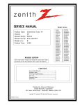
Instructions – Parts List
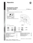
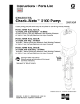
Parts
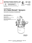
STAINLESS STEEL
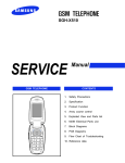
Dura–Flot 600 Pumps
308350F
With Severe–Duty Rod and Cylinder
Read warnings and instructions.
See page 2 for model numbers and maximum
working pressures.
* See page 2 for models that are
certified and
approved.
Model 686615
04373
04498
Model 237634
Model 236464
GRACO INC.ąP.O. BOX 1441ąMINNEAPOLIS, MNą55440-1441
Copyright 2002, Graco Inc. is registered to I.S. EN ISO 9001
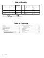
List of Models
Pump Part No.
and Series
Pump Model
Displacement
Pump Part No.
and Series
Ratio
Maximum Fluid
Working Pressure
Maximum Air
Input Pressure
* 237634,
Series A
Bulldogr
236458,
Series A
41:1
28.3 MPa, 283 bar
(4100 psi)
0.7 MPa, 7 bar
(100 psi)
* 236464,
Series A
Reduced Icing
Quiet Bulldogr
236458,
Series A
41:1
28.3 MPa, 283 bar
(4100 psi)
0.7 MPa, 7 bar
(100 psi)
Senatorr
241177,
Series A
25:1
12 MPa, 117 bar
(1700 psi)
0.7 MPa, 7 bar
(100 psi)
686615,
Series A
* This model is
certified and
approved.
Table of Contents
Warnings . . . . . . . . . . . . . . . . . . . . . . . . . . . . . . . . . . . . . . 3
Installation . . . . . . . . . . . . . . . . . . . . . . . . . . . . . . . . . . . . . 7
Operation/Maintenance . . . . . . . . . . . . . . . . . . . . . . . . 10
Troubleshooting Chart . . . . . . . . . . . . . . . . . . . . . . . . . 13
Service . . . . . . . . . . . . . . . . . . . . . . . . . . . . . . . . . . . . . . 14
Required Tools . . . . . . . . . . . . . . . . . . . . . . . . . . . . 14
Disconnecting the Displacement Pump . . . . . . . 14
Reconnecting the Displacement Pump . . . . . . . . 14
Displacement Pump Service . . . . . . . . . . . . . . . . 16
2
308350
Parts Drawings and Parts Lists . . . . . . . . . . . . . . . . . .
Pump Assemblies . . . . . . . . . . . . . . . . . . . . . . . . . .
Displacement Pump . . . . . . . . . . . . . . . . . . . . . . . .
Technical Data . . . . . . . . . . . . . . . . . . . . . . . . . . . . . . . .
Dimensions . . . . . . . . . . . . . . . . . . . . . . . . . . . . . . . . . . .
Mounting Hole Layout . . . . . . . . . . . . . . . . . . . . . . . . . .
Warranty . . . . . . . . . . . . . . . . . . . . . . . . . . . . . . . . . . . . .
Graco Information . . . . . . . . . . . . . . . . . . . . . . . . . . . . .
21
21
23
25
27
27
28
28
Symbols
Warning Symbol
Caution Symbol
WARNING
CAUTION
This symbol alerts you to the possibility of serious
injury or death if you do not follow the instructions.
This symbol alerts you to the possibility of damage to
or destruction of equipment if you do not follow the
instructions.
WARNING
EQUIPMENT MISUSE HAZARD
Equipment misuse can cause the equipment to rupture or malfunction and result in serious injury.
INSTRUCTIONS
D This equipment is for professional use only.
D Read all instruction manuals, tags, and labels before operating the equipment.
D Use the equipment only for its intended purpose. If you are uncertain about usage, call your Graco
distributor.
D Do not alter or modify this equipment. Use only genuine Graco parts and accessories.
D Check equipment daily. Repair or replace worn or damaged parts immediately.
D Do not exceed the maximum working pressure of the lowest rated system component. Refer to the
Technical Data on page 25 for the maximum working pressure of this equipment.
D Use fluids and solvents which are compatible with the equipment wetted parts. Refer to the Technical Data section of all equipment manuals. Read the fluid and solvent manufacturer’s warnings.
D Do not use hoses to pull equipment.
D Route hoses away from traffic areas, sharp edges, moving parts, and hot surfaces. Do not expose
Graco hoses to temperatures above 82_C (180_F) or below –40_C (–40_F).
D Wear hearing protection when operating this equipment.
D Do not lift pressurized equipment.
D Comply with all applicable local, state, and national fire, electrical, and safety regulations.
308350
3
WARNING
INJECTION HAZARD
Spray from the gun, hose leaks, or ruptured components can inject fluid into your body and cause
extremely serious injury, including the need for amputation. Fluid splashed in the eyes or on the skin
can also cause serious injury.
D Fluid injected into the skin might look like just a cut, but it is a serious injury. Get immediate medical attention.
D Do not point the gun at anyone or at any part of the body.
D Do not put your hand or fingers over the spray tip.
D Do not stop or deflect leaks with your hand, body, glove or rag.
D Do not “blow back” fluid; this is not an air spray system.
D Always have the tip guard and the trigger guard on the gun when spraying.
D Check the gun diffuser operation weekly. Refer to the gun manual.
D Be sure the gun trigger safety operates before spraying.
D Lock the gun trigger safety when you stop spraying.
D Follow the Pressure Relief Procedure on page 10 whenever you: are instructed to relieve pressure; stop spraying; clean, check, or service the equipment; and install or clean the spray tip.
D Tighten all fluid connections before operating the equipment.
D Check the hoses, tubes, and couplings daily. Replace worn, damaged, or loose parts immediately.
Permanently coupled hoses cannot be repaired; replace the entire hose.
D Use only Graco approved hoses. Do not remove any spring guard that is used to help protect the
hose from rupture caused by kinks or bends near the couplings.
MOVING PARTS HAZARD
Moving parts, such as the air motor piston, can pinch or amputate your fingers.
D Keep clear of all moving parts when starting or operating the pump.
D Before servicing the equipment, follow the Pressure Relief Procedure on page 10 to prevent the
equipment from starting unexpectedly.
4
308350
WARNING
FIRE AND EXPLOSION HAZARD
Improper grounding, poor ventilation, open flames or sparks can cause a hazardous condition and
result in a fire or explosion and serious injury.
D Ground the equipment and the object being sprayed. Refer to Grounding on page 7.
D If there is any static sparking or you feel an electric shock while using this equipment, stop spraying immediately. Do not use the equipment until you identify and correct the problem.
D Provide fresh air ventilation to avoid the buildup of flammable fumes from solvents or the fluid
being sprayed.
D Keep the spray area free of debris, including solvent, rags, and gasoline.
D Electrically disconnect all equipment in the spray area.
D Extinguish all open flames or pilot lights in the spray area.
D Do not smoke in the spray area.
D Do not turn on or off any light switch in the spray area while operating or if fumes are present.
D Do not operate a gasoline engine in the spray area.
TOXIC FLUID HAZARD
Hazardous fluid or toxic fumes can cause serious injury or death if splashed in the eyes or on the skin,
inhaled, or swallowed.
D Know the specific hazards of the fluid you are using.
D Store hazardous fluid in an approved container. Dispose of hazardous fluid according to all local,
state and national guidelines.
D Always wear protective eyewear, gloves, clothing and respirator as recommended by the fluid and
solvent manufacturer.
308350
5
Notes
6
308350
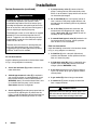
Installation
3. Air compressor: follow manufacturer’s recommendations.
General Information
NOTE: Reference numbers and letters in parentheses
in the text refer to the callouts in the figures and the
parts drawing.
NOTE: Always use Genuine Graco Parts and Accessories, available from your Graco distributor. Refer to
Product Data Sheet, Form No. 305724. If you supply
your own accessories, be sure they are adequately
sized and pressure rated for your system.
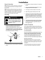
Grounding
WARNING
FIRE AND EXPLOSION HAZARD
Before operating the pump, ground the
system as explained below. Also read
the section FIRE AND EXPLOSION
HAZARD on page 5.
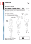
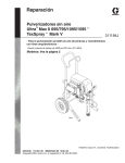
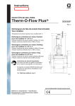
1. Pump: use a ground wire and clamp. See Fig. 1.
Loosen the grounding lug locknut (W) and
washer (X). Insert one end of a 1.5 mm@ (12 ga)
minimum ground wire (Y) into the slot in lug (Z)
and tighten the locknut securely. Connect the other
end of the wire to a true earth ground. Order Part
No. 237569 Ground Wire and Clamp.
4. Spray gun: ground through connection to a properly grounded fluid hose and pump.
5. Fluid supply container: follow your local code.
6. Object being sprayed: follow your local code.
7. Solvent pails used when flushing: follow your local
code. Use only metal pails, which are conductive,
placed on a grounded surface. Do not place the
pail on a nonconductive surface, such as paper or
cardboard, which interrupts the grounding continuity.
8. To maintain grounding continuity when flushing or
relieving pressure, hold a metal part of the spray
gun firmly to the side of a grounded metal pail,
then trigger the gun.
System Accessories
Fig. 2 is only a guide for selecting and installing system components and accessories. Contact your Graco
distributor for assistance in designing a system to suit
your particular needs.
Air and Fluid Hoses
Be sure all air hoses (H) and fluid hoses (N and P) are
properly sized and pressure-rated for your system.
Use only electrically conductive hoses. Fluid hoses
must have spring guards on both ends. Use a whip
hose (P) and a swivel (R) between the main fluid
hose (N) and the gun (S) to allow freer gun movement.
W
X
Y
Z
Mounting Accessories
Fig. 1
Mount the pump (A) to suit the type of installation
planned. Fig. 2 illustrates a wall mount system. Pump
dimensions and the mounting hole layout are shown
on page 27.
2. Air and fluid hoses: use only electrically conductive
hoses.
If you are using a floor stand, refer to its separate
manual for installation and operation instructions.
0864
308350
7
Installation
System Accessories (continued)
D
A pump runaway valve (C) senses when the
pump is running too fast and automatically shuts
off the air to the motor. A pump which runs too fast
can be seriously damaged.
D
An air manifold (G) has a 3/4 npsm(f) swivel air
inlet. It mounts to the pump support bracket, and
provides ports for connecting lines to air-powered
accessories.
D
An air line filter (J) removes harmful dirt and
moisture from the compressed air supply. Also,
install a drain valve (W) at the bottom of each air
line drop, to drain off moisture.
D
A second bleed-type air valve (K) isolates the air
line accessories for servicing. Locate upstream
from all other air line accessories.
WARNING
A bleed-type master air valve (E) and a fluid drain
valve (M) are required in your system. These
accessories help reduce the risk of serious injury,
including fluid injection and splashing of fluid in the
eyes or on the skin, and injury from moving parts if
you are adjusting or repairing the pump.
The bleed-type master air valve relieves air trapped
between this valve and the pump after the air is
shut off. Trapped air can cause the pump to cycle
unexpectedly. Locate the valve close to the pump.
Order Part No. 107141.
The fluid drain valve assists in relieving fluid pressure in the displacement pump, hose, and gun.
Triggering the gun to relieve pressure may not be
sufficient. Order Part No. 235992.
Fluid Line Accessories
Install the following accessories in the locations shown
in Fig. 2, using adapters as necessary:
D
A fluid filter (L) with a 60 mesh (250 micron)
stainless steel element, to filter particles from the
fluid as it leaves the pump.
D
A fluid drain valve (M), which is required in your
system, helps relieve fluid pressure in the hose
and gun (see the WARNING at left).
D
A gun (S) dispenses the fluid. The gun shown in
Fig. 2 is an airless spray gun for light to medium
viscosity fluids.
D
A gun swivel (R) allows freer gun movement.
D
A suction kit (T) allows the pump to draw fluid
from a supply container.
Air Line Accessories
Install the following accessories in the locations shown
in Fig. 2, using adapters as necessary:
D
D
D
8
An air line lubricator (D) provides automatic air
motor lubrication.
A bleed-type master air valve (E) is required in
your system to relieve air trapped between it and
the air motor when the valve is closed (see the
WARNING above). Be sure the bleed valve is easily accessible from the pump, and is located
downstream from the air regulator.
CAUTION
An air regulator (F) controls pump speed and outlet pressure by adjusting the air pressure to the
pump. Locate the regulator close to the pump, but
upstream from the bleed-type master air valve.
308350
To prevent intake valve damage, always apply PTFE
tape to the female threads of the intake valve before
connecting a suction hose or fitting to the intake.
Installation
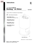
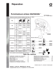
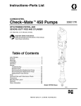
TYPICAL INSTALLATION
KEY
A
B
C
D
E
F
G
H
Pump
Wall Bracket
Pump Runaway Valve
Air Line Lubricator
Bleed-Type Master Air Valve
(required, for pump)
Pump Air Regulator
Air Manifold
Electrically Conductive
Air Supply Hose
R
S
T
Y
Gun Swivel
Airless Spray Gun
Suction Kit
Ground Wire and Clamp
(required; see page 7
for installation instructions)
W Air Line Drain Valve
J
K
Air Line Filter
Bleed-Type Master Air Valve
(for accessories)
L Fluid Filter
M Fluid Drain Valve (required)
N Electrically Conductive
Fluid Supply Hose
P Fluid Whip Hose
J
K
MAIN AIR LINE
Y
D
A
S
E
F
C
G
B
H
R
P
L
N
W
M
T
04496
Fig. 2
308350
9
Operation/Maintenance
Pressure Relief Procedure
WARNING
INJECTION HAZARD
The system pressure must be manually
relieved to prevent the system from
starting or spraying accidentally. Fluid
under high pressure can be injected through the
skin and cause serious injury. To reduce the risk of
an injury from injection, splashing fluid, or moving
parts, follow the Pressure Relief Procedure
whenever you:
D
D
D
D
are instructed to relieve the pressure,
stop spraying,
check or service any of the system equipment,
or install or clean the spray tips.
1. Lock the gun trigger safety.
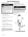
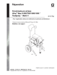
Packing Nut/Wet-Cup
Before starting, fill the packing nut (8) 1/3 full with
Graco Throat Seal Liquid (TSL) or compatible solvent.
See Fig. 3.
WARNING
To reduce the risk of serious injury whenever you
are instructed to relieve pressure, always follow the
Pressure Relief Procedure at left.
The packing nut is torqued at the factory and is ready
for operation. If it becomes loose and there is leaking
from the throat packings, relieve pressure, then torque
the nut to 61–75 NSm (45–55 ft-lb) using the supplied
wrench (110). Do this whenever necessary. Do not
overtighten the packing nut.
1
Torque to 61–75 NSm
(45–55 ft-lb)
2. Shut off the air supply to the pump.
3. Close the bleed-type master air valve (required in
your system).
Model
237634
Shown
4. Unlock the gun trigger safety.
5. Hold a metal part of the gun firmly to the side of a
grounded metal pail, and trigger the gun to relieve
pressure.
6. Lock the gun trigger safety.
1
8
110
7. Open the drain valve (required in your system),
having a container ready to catch the drainage.
8. Leave the drain valve open until you are ready to
spray again.
If you suspect that the spray tip or hose is completely
clogged, or that pressure has not been fully relieved
after following the steps above, very slowly loosen the
tip guard retaining nut or hose end coupling and relieve
pressure gradually, then loosen completely. Now clear
the tip or hose.
10
308350
04373
Fig. 3
Operation/Maintenance
Flush the Pump Before First Use
The pump is tested with lightweight oil, which is left in
to protect the pump parts. If the fluid you are using
may be contaminated by the oil, flush it out with a
compatible solvent. See Flushing on page 12.
Starting and Adjusting the Pump
1. See Fig. 2. Connect the suction kit (T) to the
pump’s fluid inlet. Place the tube into the fluid
supply.
CAUTION
To prevent intake valve damage, always apply PTFE
tape to the female threads of the intake valve before
connecting a suction hose or fitting to the intake.
2. Close the air regulator (F).
3. Open the pump’s bleed-type master air valve (E).
4. Hold a metal part of the gun (S) firmly to the side
of a grounded metal pail and hold the trigger open.
5. Slowly open the regulator until the pump starts.
6. Cycle the pump slowly until all air is pushed out
and the pump and hoses are fully primed.
7. Release the gun trigger and lock the trigger safety.
The pump should stall against pressure.
8. If the pump fails to prime properly, open the drain
valve (M). Use the drain valve as a priming valve
until the fluid flows from the valve. Close the valve.
FOR MODEL 686615 ONLY
If the pump fails to prime properly, open the bleeder
valve plug (113) slightly. Use the bleed hole on the
underside of the valve body (112), as a priming valve
until the fluid appears at the hole, see parts page 22.
Close the plug.
WARNING
INJECTION HAZARD
To reduce the risk of fluid injection, do
not use your hand or fingers to cover
the bleed hole on the underside of the
bleeder valve body (112) when priming the pump.
Use a crescent wrench to open and close the
bleeder plug (113). Keep your hands away from the
bleed hole.
NOTE: When changing fluid containers with the hose
and gun already primed, open the drain valve (M), or
the bleeder valve plug (113) for model 686615 to help
prime the pump and vent air before it enters the hose.
Close the drain valve or the plug for model 686615
when all air is eliminated.
CAUTION
Do not allow the pump to run dry. It will quickly
accelerate to a high speed, causing damage. If your
pump is running too fast, stop it immediately and
check the fluid supply. If the container is empty and
air has been pumped into the lines, refill the container and prime the pump and the lines, or flush and
leave it filled with a compatible solvent. Eliminate all
air from the fluid system.
9. With the pump and lines primed, and with adequate air pressure and volume supplied, the pump
will start and stop as you open and close the gun.
In a circulating system, the pump will speed up or
slow down on demand, until the air supply is shut
off.
WARNING
COMPONENT RUPTURE HAZARD
To reduce the risk of overpressurizing
your system, which could cause component rupture and serious injury, never
exceed the specified Maximum Incoming Air Pressure to the pump (see Technical Data, page 25).
10. Use the air regulator (F) to control pump speed
and fluid pressure. Always use the lowest air
pressure necessary to get the desired results.
Higher pressures cause premature tip and pump
wear.
308350
11
Operation/Maintenance
Shutdown and Care of the Pump
WARNING
To reduce the risk of serious injury whenever you
are instructed to relieve pressure, always follow the
Pressure Relief Procedure on page 10.
For overnight shutdown, stop the pump at the bottom
of its stroke to prevent fluid from drying on the exposed displacement rod and damaging the throat
packings. Relieve the pressure.
Always flush the pump before the fluid dries on the
displacement rod. See Flushing below.
WARNING
To reduce the risk of serious injury whenever you
are instructed to relieve pressure, always follow the
Pressure Relief Procedure on page 10.
1. Relieve the pressure.
2. Remove the spray tip from the gun.
3. Hold a metal part of the gun firmly to the side of a
grounded metal pail.
Flushing
WARNING
FIRE AND EXPLOSION HAZARD
Before flushing, read the section FIRE
AND EXPLOSION HAZARD on
page 5. Be sure the entire system and
flushing pails are properly grounded.
Refer to Grounding on page 7.
12
Flush with a fluid that is compatible with the fluid you
are pumping and with the wetted parts in your system.
Check with your fluid manufacturer or supplier for
recommended flushing fluids and flushing frequency.
Always flush the pump before fluid dries on the displacement rod.
308350
4. Start the pump. Always use the lowest possible
fluid pressure when flushing.
5. Trigger the gun.
6. Flush the system until clear solvent flows from the
gun.
7. Relieve the pressure.
Troubleshooting Chart
WARNING
To reduce the risk of serious injury whenever you
are instructed to relieve pressure, always follow the
Pressure Relief Procedure on page 10.
PROBLEM
1. Relieve the pressure.
2. Check all possible causes and problems before
disassembling the pump.
CAUSE
The pump fails to oper- Valves are closed or clogged.
ate.
The fluid hose or gun is obstructed.
SOLUTION
Clear the air line; increase the air supply.
Check that the valves are open.
Clear the hose or gun*;
use a hose with a larger ID.
Fluid has dried on the displacement rod. Clean the rod; always stop the pump at the bottom
of its stroke; keep the wet-cup 1/3 filled with a
compatible solvent.
Air motor parts are dirty, worn, or dam- Clean or repair the air motor;
aged.
see the separate motor manual.
The pump operates, The air line is restricted or the air supply Clear the air line; increase the air supply.
but the output is low on is inadequate. Valves are closed or Check that the valves are open.
both strokes.
clogged.
The fluid hose or gun is obstructed;
the fluid hose ID is too small.
Clear the hose or gun*;
use a hose with a larger ID.
Worn packings in the displacement Replace the packings.
pump.
Air motor parts are dirty, worn, or dam- Clean or repair the air motor;
aged.
see the separate motor manual.
Held open or worn intake valve.
Clear or service the intake valve.
The pump operates, Held open or worn intake valve.
but the output is low on
the downstroke.
Clear or service the intake valve.
The pump operates, Held open or worn piston valve
but the output is low on or packings.
the upstroke.
Clear the piston valve; replace the packings.
The pump’s speed is The fluid supply is exhausted.
erratic or accelerated.
Refill the supply and prime the pump.
*
Held open or worn piston valve
or packings.
Clear the piston valve; replace the packings.
Held open or worn intake valve.
Clear or service the intake valve.
To determine if the fluid hose or gun is obstructed, relieve the pressure. Disconnect the fluid hose and place a
container at the pump fluid outlet to catch any fluid. Turn on the air just enough to start the pump. If the pump
starts when the air is turned on, the obstruction is in the fluid hose or gun.
NOTE: If you experience air motor icing, call your Graco distributor.
308350
13
Service
Required Tools
D
D
D
D
D
D
D
D
Set of adjustable wrenches
Large pipe wrench
2–3/4 in. socket wrench
Torque wrench
Rubber mallet
O-ring pick
Large vise
Plastic or wooden block, approximately
6 in. square x 1 in. thick
Thread lubricant
Thread sealant
D
D
Disconnecting the Displacement Pump
1. Flush the pump, if possible. Stop the pump at the
bottom of its stroke.
WARNING
To reduce the risk of serious injury whenever you
are instructed to relieve pressure, always follow the
Pressure Relief Procedure on page 10.
2. Relieve the pressure.
3. Disconnect the air hose and fluid hose.
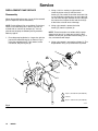
4. Disconnect the displacement pump (109) from the
motor (101) as follows. Note the relative position of
the pump’s fluid outlet (U) to the air inlet (V) of the
motor. If the motor does not require servicing,
leave it attached to its mounting.
CAUTION
Be sure to use two people when lifting, moving, or
disconnecting the entire pump. This pump is too
heavy for one person. If you are disconnecting the
displacement pump from a motor which is still
mounted (for example, on a wall bracket), only one
person is required. The displacement pump weighs
approximately 13 kg (29 lb).
If the pump is mounted on a cart, slowly tip the cart
backward until the handle rests on the ground, then
disconnect the displacement pump.
14
308350
5. Using an adjustable wrench (or hammer and
punch), unscrew the coupling nut (106) from the
motor shaft (W). Do not lose or drop the coupling
collars (107). See Fig. 4.
6. Hold the tie rod flats with a wrench to keep the
rods from turning. Unscrew the nuts (108) from the
tie rods (105). Carefully remove the displacement
pump (109) from the motor (101).
7. Refer to page 16 for displacement pump service.
To service the air motor, refer to the separate
motor manual, supplied.
Reconnecting the Displacement Pump
1. Make sure the coupling nut (106) and the coupling
collars (107) are in place on the displacement
rod (1). See Fig. 4.
2. Have one person hold the displacement pump
while another reconnects it to the motor (see the
CAUTION at left). Orient the pump’s fluid
outlet (U) to the air inlet (V) as was noted in step 4
under Disconnecting the Displacement Pump.
Position the displacement pump (109) on the tie
rods (105).
3. Screw the nuts (108) onto the tie rods (105) and
torque to 68–81 NSm (50–60 ft-lb).
4. Screw the coupling nut onto the motor shaft (W)
loosely. Hold the motor shaft flats with a wrench to
keep it from turning. Use an adjustable wrench to
tighten the coupling nut. Torque to 195–210 NSm
(145–155 ft-lb).
5. Reconnect all hoses. Reconnect the ground wire if
it was disconnected. Fill the packing nut (8) 1/3 full
of Graco Throat Seal Liquid or compatible solvent.
6. Turn on the air supply. Run the pump slowly to
ensure proper operation.
WARNING
To reduce the risk of serious injury whenever you
are instructed to relieve pressure, always follow the
Pressure Relief Procedure on page 10.
7. Before returning the pump to production, relieve
the pressure and retorque the packing nut (8)
to 61–75 NSm (45–55 ft-lb).
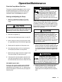
Service
V
Model 237634 Shown
101
W
107
106
2
110
1
3
105
3
108
8
1
109
U
1
Torque to 61–75 NSm (45–55 ft-lb)
2
Torque to 195–210 NSm (145–155 ft-lb)
3
Torque to 68–81 NSm (50–60 ft-lb)
04377
Fig. 4
308350
15
Service
2. Using a 2–3/4 in. socket or a pipe wrench, unscrew the intake valve (5) from the intake
housing (7). Be careful to catch the intake ball (13)
as you remove the intake valve, so that it does not
fall and suffer damage. Remove the seal (30) from
the intake valve. Inspect the ball and the seat (D)
of the intake valve for wear or damage.
DISPLACEMENT PUMP SERVICE
Disassembly
When disassembling the pump, lay out all the removed
parts in sequence, to ease reassembly.
NOTE: Packing Repair Kits are available. For the best
results, use all the new parts in the kit. Kit parts are
marked with an asterisk, for example (3*). You can
also convert the pump to different packing materials.
Refer to page 24.
3. Using a pipe wrench, remove the intake
housing (7) from the cylinder (2).
NOTE: These instructions are written with the pump
separating at joint A. If it separates at joint B, disassemble it at that joint, place the intake housing (7) in a
vise, and continue with step 4.
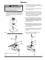
1. Place the pump lengthwise in a large vise, with the
jaws on the outlet housing (6) as shown in Fig. 5.
Using the supplied wrench (110), loosen, but do
not remove, the packing nut (8).
4. Using a pipe wrench, unscrew the cylinder (2). The
displacement rod (1) may come with the cylinder.
5
D
1
6
1
3
7
2
13*
30*
2
2
A
1
B
8
1
Torque to 325–353 NSm (240–260 ft-lb).
2
Lubricate.
3
Torque to 190–217 NSm (140–160 ft-lb).
04492A
Fig. 5
16
308350
Service
6. Shine a light into the cylinder (2) to inspect the
inner surface for scoring or wear. Remove the two
seals (11) from the cylinder.
CAUTION
To reduce the possibility of costly damage to the
rod (1) and cylinder (2), always use a plastic or
wooden block to help drive the rod out of the cylinder. Never hit the rod with a hammer.
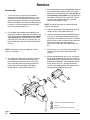
7. Place the flats of the piston seat housing (10) in a
vise, as shown in Fig. 7.
8. Using an adjustable wrench, unscrew the piston
ball housing (9) from the piston seat housing. Be
careful to catch the piston ball (12) as you separate the piston seat housing and ball housing, so
that it does not fall and suffer damage.
5. Turn the cylinder (2) upside down and strike the
top of the rod (1) on a plastic or wooden block until
the piston comes free. Pull the rod and piston from
the cylinder, being careful not to scratch the parts.
See Fig. 6.
9. Examine the displacement rod (1) for scratches or
other damage. Only if the rod needs replacement, place the piston ball housing (9) in a vise
and unscrew the rod, using an adjustable wrench
on the flats of the rod.
10. Remove the glands and v-packings (P) and the
ball (12) from the piston seat housing (10). Inspect
the ball seat (E) and ball guides (F) for wear or
damage. See Fig. 9.
1
2
11. Unscrew the packing nut (8) from the outlet housing (6). Remove the glands and v-packings (T).
See Fig. 9.
04518
12. Clean all parts with a compatible solvent and
inspect them for wear or damage.
Fig. 6
1
1
1
9
9
10
1
1
12*
1
10
Torque to 258–285 NSm (190–210 ft–lb).
04495
Fig. 7
04494
308350
17
Service
Reassembly
1. If it was necessary to remove the piston ball
housing (9) from the displacement rod (1), clean
the threads of the rod and the ball housing, and
apply thread sealant. Screw the ball housing onto
the rod, hand tight. Place the flats of the piston ball
housing in a vise and torque the rod to 258–285
NSm (190–210 ft-lb). See Fig. 9.
2. For standard displacement pump 236458, place
the piston packings on the piston seat housing (10)
in the following order, with the lips of the v-packings facing up: the female gland (4*), one PTFE r
v-packing (18*), four leather v-packings (19*), and
the male gland (3*). See the Piston Packing Detail
in Fig. 9.
NOTE: To convert the pump to a different packing
material, see page 24.
3. Place the flats of the piston seat housing (10) in a
vise. Apply thread sealant to the threads of the
piston seat housing. Place the ball (12*) on the
seat. Screw the piston ball housing (9) onto the
piston seat housing hand tight, then torque
to 258–285 NSm (190–210 ft-lb). See Fig. 7.
6
1
4. For standard displacement pump 236458, lubricate
the throat packings and place them in the outlet
housing (6) in the following order, with the lips of
the v-packings facing down: the male gland (3*),
four leather v-packings (19*), one PTFErv-packing (18*), and the female gland (4*). See the
Throat Packing Detail in Fig. 9.
NOTE: To convert the pump to a different packing
material, see page 24.
5. Lubricate the threads of the packing nut (8), and
loosely install it in the outlet housing (6).
6. Lubricate the piston packings. Slide the displacement rod (1) and piston assembly down into the
cylinder (2). The cylinder is symmetrical, so either
end may face up. Use a rubber mallet to drive the
rod into the cylinder, until the piston seat
housing (10) is located in the middle of the cylinder.
7. Install the seal (11*) on the top of the cylinder (2).
Lubricate the seal and the top threads of the
cylinder.
8. Place the outlet housing (6) in a vise, as shown in
Fig. 8. Slide the displacement rod (1) up into the
outlet housing, then screw the cylinder (2) into the
outlet housing handtight. The threads will engage
easily until the seal (11*) contacts the sealing
surface of the outlet housing. The top of the rod
will protrude from the packing nut (8).
2
5
7
3
1
11*
2
1
8
1
Torque to 325–353 NSm (240–260 ft-lb).
2
Lubricate.
3
Torque to 190–217 NSm (140–160 ft-lb).
05127
Fig. 8
18
308350
Service
1
Torque to 61–75 NSm (45–55 ft-lb).
6
Lips face up.
2
Torque to 325–353 NSm (240–260 ft-lb).
7
Lips face down.
3
Torque to 258–285 NSm (190–210 ft-lb).
8
See the Throat Packing Detail at left.
4
Lubricate.
9
See the Piston Packing Detail at left.
5
Apply thread sealant.
10
1
Torque to 190–217 NSm (140–160 ft-lb).
8
1
Throat Packing Detail
(Displacement Pump 236458 Shown;
see page 24 for options.)
6
8 (Ref)
*4
7
4
T
*18
8
*19
*3
6 (Ref)
*11
4
2
Piston Packing Detail
(Displacement Pump 236458 Shown;
see page 24 for options.)
9 (Ref)
3
5
9
*12
F
2 (Ref)
E
7
10 (Ref)
*3
*19
6
4
7 (Ref)
9
10
P
3
S
4
*11
*18
*4
2
D
4
*30
*11 (Ref)
5
10
13*
05468
Fig. 9
308350
19
Service
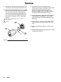
9. Install the seal (30*) on the intake valve (5). Lubricate the seal and the threads of the intake valve.
10. One end of the intake housing (7) has a rounded
ball cavity (S) on the inside (see Fig. 9). Install the
ball (13*) in this cavity, then screw the intake
valve (5) into the intake housing handtight. See
Fig. 10. The threads will engage easily until the
seal contacts the sealing surface of the intake
housing.
1
Orient so the end with the ball cavity (S, see Fig. 9)
faces the ball (13*).
2
Lubricate.
2
11. Install the seal (11*) on the bottom of the
cylinder (2). See Fig. 8. Lubricate the seal and the
threads of the cylinder. Screw the intake
housing (7) onto the cylinder handtight. The
threads will engage easily until the seal contacts
the sealing surface of the intake housing.
12. Using a pipe wrench, torque the intake housing (7)
to 325–353 NSm (240–260 ft-lb). This will also
torque the cylinder (2) into the outlet housing (6).
See Fig. 8.
13. Using a 2–3/4 in. socket or a pipe wrench, torque
the intake valve (5) to 190–217 NSm (140–160
ft-lb).
5
14. Torque the packing nut (8) to 61–75 NSm (45–55
ft-lb).
1
7
15. Reconnect the displacement pump to the air motor
as explained on page 14.
13*
30*
2
04493A
Fig. 10
20
308350
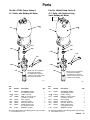
Parts
Part No. 237634 Pump, Series A
41:1 Ratio, with Bulldog Air Motor
Part No. 236464 Pump, Series A
41:1 Ratio, with Reduced Icing
Quiet Bulldog Air Motor
102Y
101
102Y
101
107{
{105
107{
106{
106{
{105
110{
110{
{108
{108
109
{These parts are included in
109
Connection Kit 235417.
For applications requiring
stainless steel tie rods, order
Connection Kit 235418.
{These parts are included in
Connection Kit 235417.
For applications requiring
stainless steel tie rods, order
Connection Kit 235418.
04377
04497
Ref.
No.
Part No.
Description
101
208356
AIR MOTOR, Bulldog
See 307049 for parts
LABEL, warning
ROD, tie; 224 mm (8.82”)
shoulder to shoulder
NUT, coupling
COLLAR, coupling
NUT, hex; M16 x 2.0
PUMP, displacement
See page 23 for parts
WRENCH, spanner
102Y 176529
105{ 190000
106{
107{
108{
109
186925
184129
106166
236458
110{
112887
Qty.
1
1
3
1
2
3
1
1
Y Replacement Danger and Warning labels, tags and cards
are available at no cost.
Ref.
No.
Part No.
Description
101
237001
AIR MOTOR, Bulldog
See 307304 for parts
LABEL, warning
ROD, tie; 224 mm (8.82”)
shoulder to shoulder
NUT, coupling
COLLAR, coupling
NUT, hex; M16 x 2.0
PUMP, displacement
See page 23 for parts
WRENCH, spanner
102Y 176529
105{ 190000
106{
107{
108{
109
186925
184129
106166
236458
110{
112887
Qty.
1
1
3
1
2
3
1
1
Y Replacement Danger and Warning labels, tags and cards
are available at no cost.
308350
21
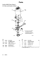
Parts
Part No. 686615 Pump, Series A
25:1 Ratio, with Senator Air Motor
101
102Y
107{
{105
106{
110{
{108
109
112
113
111
{ These parts are included in
Connection Kit 235417.
For applications requiring
stainless steel tie rods, order
Connection Kit 235418.
9204A
9204C
Ref.
No.
101
Part No.
217540
102Y 176529
105{ 190000
106{
107{
108{
22
186925
184129
106166
308350
Description
AIR MOTOR, Senator
See 307592 for parts
LABEL, warning
ROD, tie; 224 mm (8.82”)
shoulder to shoulder
NUT, coupling
COLLAR, coupling
NUT, hex; M16 x 2.0
Qty.
1
1
3
1
2
3
Ref.
No.
Part No.
Description
109
241177
110{
112887
PUMP, displacement
See page 23 for parts
WRENCH, spanner
1
1
111
190737
CYLINDER, intake
1
112
184392
HOUSING, valve
1
113
190293
PLUG, valve
1
Qty.
Y Replacement Danger and Warning labels, tags and cards
are available at no cost.
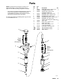
Parts
NOTE: The parts listed on this page are common to all
displacement pumps covered in this manual. Refer to
page 24 for the different packing configurations available.
* These parts are included in Repair Kit 237234, which may
be purchased separately for standard Displacement
Pump 236458. See page 24. They are also included in
Optional Kits 237236, 237238, and 237609.
Y Replacement Danger and Warning labels, tags and cards
are available at no cost.
8
Ref
No.
Part
No.
1
2
5
190172
184503
236585
6
7
8
9
10
237731
190394
236578
189406
222929
11*
12*
109205
101822
13*
102973
17
20Y
21Y
30*
101748
172477
172479
166073
Throat
Packing
Stack
(see page 24)
Description
Qty
ROD, displacement; stainless steel
CYLINDER; stainless steel
VALVE, intake; stainless steel
w/tungsten carbide seat
HOUSING, outlet; stainless steel
HOUSING, intake; stainless steel
PACKING NUT; stainless steel
HOUSING, ball, piston; stainless steel
HOUSING, seat, piston valve;
stainless steel w/tungsten carbide seat
SEAL; PTFE r
BALL, piston; stainless steel;
0.625” (16 mm) dia.
BALL, intake; stainless steel;
1–1/4” (31.8 mm) dia.
PLUG, pipe, socket hd; 3/8 npt
TAG, warning (not shown)
TAG, warning (not shown)
SEAL; PTFE r
1
1
1
1
1
1
1
1
2
1
1
1
1
1
1
9
17
6
Piston
Packing
Stack
(see page 24)
*11
12*
10
2
7
*11
13*
30*
5
1
04371A
308350
23
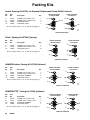
Packing Kits
Leather Packing Kit 237234, for Standard Displacement Pump 236458, Series A
Ref
No.
Part
No.
Description
3*
4*
18*
19*
184222
184172
109302
184302
GLAND, male; stainless steel
GLAND, female; stainless steel
V-PACKING; PTFE r
V-PACKING; leather
THROAT PACKINGS:
LIPS FACE DOWN
Qty
2
2
2
8
PISTON PACKINGS:
LIPS FACE UP
*4
*3
18*
*19
*19
*3
*4
18*
* Kit also includes items 11, 12, 13, and 30 (see page 23).
0805
0806
LUBRICATE PACKINGS
Teflonr Packing Kit 237236 (Optional)
Ref
No.
Part
No.
Description
3*
4*
18*
184222
184172
109302
GLAND, male; stainless steel
GLAND, female; stainless steel
V-PACKING; PTFE r
THROAT PACKINGS:
LIPS FACE DOWN
Qty
*4
*3
*18
*18
*3
*4
2
2
10
* Kit also includes items 11, 12, 13, and 30 (see page 23).
PISTON PACKINGS:
LIPS FACE UP
0805
0806
LUBRICATE PACKINGS
UHMWPE/Leather Packing Kit 237238 (Optional)
Ref
No.
Part
No.
Description
3*
4*
18*
19*
184222
184172
109252
184302
GLAND, male; stainless steel
GLAND, female; stainless steel
V-PACKING; UHMWPE
V-PACKING; leather
THROAT PACKINGS:
LIPS FACE DOWN
Qty
2
2
6
4
*4
*18
PISTON PACKINGS:
LIPS FACE UP
*3
19*
*18
19*
* Kit also includes items 11, 12, 13, and 30 (see page 23).
*3
*4
0805
0806
LUBRICATE PACKINGS
UHMWPE/PTFErPacking Kit 237609 (Optional)
Ref
No.
Part
No.
Description
3*
4*
18*
19*
184222
184172
109252
109302
GLAND, male; stainless steel
GLAND, female; stainless steel
V-PACKING; UHMWPE
V-PACKING; PTFE r
THROAT PACKINGS:
LIPS FACE DOWN
Qty
* Kit also includes items 11, 12, 13, and 30 (see page 23).
2
2
6
4
*4
*18
*3
PISTON PACKINGS:
LIPS FACE UP
*3
19*
*18
19*
*4
0805
0806
LUBRICATE PACKINGS
24
308350
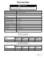
Technical Data
WARNING
Be sure that all fluids and solvents used are chemically compatible with the
Wetted Parts listed below. Always read the manufacturer’s literature before
using fluid or solvent in this pump.
Category
Data
Maximum fluid working pressure
28.3 MPa, 283 bar (4100 psi)
Maximum air input pressure
0.7 MPa, 7 bar (100 psi)
Ratio
41:1
Pump cycles per 3.8 liters
(1 gallon)
26
Fluid flow at 60 cycles per minute
8.7 liters/min (2.3 gpm)
Air motor piston effective area
248 cm@ (38 in.@)
Stroke length
120 mm (4.75 in.)
Displacement pump effective
area
6 cm@ (0.93 in.@)
Maximum operating temperature
82_C (180_F)
Air inlet size
3/4 npsm(f)
Fluid inlet size
1–1/2” npt(f)
Fluid outlet size
3/4 npt(f)
Pump weight
approx. 39 kg (86 lb)
Displacement pump weight
approx. 13 kg (29 lb)
Wetted parts
304, 440 and 17–4 PH Grades of Stainless Steel; Tungsten Carbide; PTFE; r
Leather
Teflonr is a registered trademark of the DuPont Co.
Sound Pressure Levels (dBa)
(measured at 1 meter from unit)
Input Air Pressures at 15 cycles per minute
Air Motor
0.28 MPa, 2.8 bar
(40 psi)
0.48 MPa, 4.8 bar
(70 psi)
0.63 MPa, 6.3 bar
(90 psi)
0.7 MPa, 7 bar
(100 psi)
Bulldog
82.4 dB(A)
87.3 dB(A)
88.5 dB(A)
90.0 dB(A)
Reduced Icing Quiet Bulldog
81.5 dB(A)
83.6 dB(A)
85.6 dB(A)
85.8 dB(A)
Sound Power Levels (dBa)
(tested in accordance with ISO 9614–2)
Input Air Pressures at 15 cycles per minute
Air Motor
0.28 MPa, 2.8 bar
(40 psi)
0.48 MPa, 4.8 bar
(70 psi)
0.63 MPa, 6.3 bar
(90 psi)
0.7 MPa, 7 bar
(100 psi)
Bulldog
91.6 dB(A)
95.9 dB(A)
97.4 dB(A)
98.1 dB(A)
Reduced Icing Quiet Bulldog
90.2 dB(A)
93.5 dB(A)
94.9 dB(A)
93.3 dB(A)
308350
25
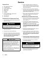
Technical Data
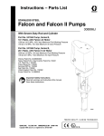
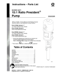
KEY:
Fluid Outlet Pressure – Black Curves
Air Consumption – Gray Curves
psi
MPa, bar
5000
35.0, 350
4000
28.0, 280
3000
21.0, 210
A
B
C
13
26
cycles/min
52
39
65
200
5.60
A
150
4.20
B
A
100
2.80
B
C
1000
7.0, 70
0
78 scfm
m#/min
250
7.00
60
2000
14.0, 140
gpm 0.0
liters/min
0.7 MPa, 7 bar (100 psi) Air Pressure
0.49 MPa, 4.9 bar (70 psi) Air Pressure
0.28 MPa, 2.8 bar (40 psi) Air Pressure
C
0.5
1.9
1.0
3.8
1.5
5.7
2.0
7.6
2.5
9.5
50
1.40
3.0
11.4
FLUID FLOW (NO. 10 WEIGHT OIL)
To find Fluid Outlet Pressure (MPa/bar/psi) at a specific fluid flow
(lpm/gpm) and operating air pressure (MPa/bar/psi):
1. Locate desired flow along bottom of chart.
2. Follow vertical line up to intersection with selected fluid outlet
pressure curve (black). Follow left to scale to read fluid outlet
pressure.
26
308350
To find Pump Air Consumption (m#/min or scfm) at a specific fluid
flow (lpm/gpm) and air pressure (MPa/bar/psi):
1. Locate desired flow along bottom of chart.
2. Read vertical line up to intersection with selected air consumption
curve (gray). Follow right to scale to read air consumption.
Dimensions
Mounting Hole
Layout
Model 237634 Shown
94.28 mm
(3.712”)
101.6 mm
(4.0”)
G
94.28 mm
(3.712”)
C
50.8 mm
(2.0”)
A
H
Three M16 x 2.0
Holes
11.1 mm
(0.437”)
DIA (4)
88 mm
(3.464”)
B
D
0653
F
E
04373
Pump
Model
A
B
C
D
E
F
G
H
237634
1105 mm
(43.50 in.)
561 mm
(22.09 in.)
544 mm
(21.42 in.)
257 mm
(10.12 in.)
1–1/2 in.
npt(f)
3/4 npt(f)
3/4 npsm(f)
1–1/2 in.
npt(f)
236464
1155 mm
(45.47 in.)
561 mm
(22.09 in.)
594 mm
(23.38 in.)
257 mm
(10.12 in.)
1–1/2 in.
npt(f)
3/4 npt(f)
3/4 npsm(f)
1–1/2 in.
npt(f)
686615
308350
27
Graco Standard Warranty
Graco warrants all equipment manufactured by Graco and bearing its name to be free from defects in material and workmanship on the
date of sale by an authorized Graco distributor to the original purchaser for use. With the exception of any special, extended, or limited
warranty published by Graco, Graco will, for a period of twelve months from the date of sale, repair or replace any part of the equipment
determined by Graco to be defective. This warranty applies only when the equipment is installed, operated and maintained in accordance with Graco’s written recommendations.
This warranty does not cover, and Graco shall not be liable for general wear and tear, or any malfunction, damage or wear caused by
faulty installation, misapplication, abrasion, corrosion, inadequate or improper maintenance, negligence, accident, tampering, or substitution of non–Graco component parts. Nor shall Graco be liable for malfunction, damage or wear caused by the incompatibility of
Graco equipment with structures, accessories, equipment or materials not supplied by Graco, or the improper design, manufacture,
installation, operation or maintenance of structures, accessories, equipment or materials not supplied by Graco.
This warranty is conditioned upon the prepaid return of the equipment claimed to be defective to an authorized Graco distributor for
verification of the claimed defect. If the claimed defect is verified, Graco will repair or replace free of charge any defective parts. The
equipment will be returned to the original purchaser transportation prepaid. If inspection of the equipment does not disclose any defect
in material or workmanship, repairs will be made at a reasonable charge, which charges may include the costs of parts, labor, and
transportation.
THIS WARRANTY IS EXCLUSIVE, AND IS IN LIEU OF ANY OTHER WARRANTIES, EXPRESS OR IMPLIED, INCLUDING BUT
NOT LIMITED TO WARRANTY OF MERCHANTABILITY OR WARRANTY OF FITNESS FOR A PARTICULAR PURPOSE.
Graco’s sole obligation and buyer’s sole remedy for any breach of warranty shall be as set forth above. The buyer agrees that no other
remedy (including, but not limited to, incidental or consequential damages for lost profits, lost sales, injury to person or property, or any
other incidental or consequential loss) shall be available. Any action for breach of warranty must be brought within two (2) years of the
date of sale.
Graco makes no warranty, and disclaims all implied warranties of merchantability and fitness for a particular purpose in connection
with accessories, equipment, materials or components sold but not manufactured by Graco. These items sold, but not manufactured
by Graco (such as electric motors, switches, hose, etc.), are subject to the warranty, if any, of their manufacturer. Graco will provide
purchaser with reasonable assistance in making any claim for breach of these warranties.
In no event will Graco be liable for indirect, incidental, special or consequential damages resulting from Graco supplying equipment
hereunder, or the furnishing, performance, or use of any products or other goods sold hereto, whether due to a breach of contract,
breach of warranty, the negligence of Graco, or otherwise.
FOR GRACO CANADA CUSTOMERS
The parties acknowledge that they have required that the present document, as well as all documents, notices and legal proceedings
entered into, given or instituted pursuant hereto or relating directly or indirectly hereto, be drawn up in English. Les parties reconnaissent avoir convenu que la rédaction du présente document sera en Anglais, ainsi que tous documents, avis et procédures judiciaires
exécutés, donnés ou intentés à la suite de ou en rapport, directement ou indirectement, avec les procedures concernées.
Graco Information
TO PLACE AN ORDER, contact your Graco distributor, or call one of the following numbers
to identify the distributor closest to you:
1–800–367–4023 Toll Free
612–623–6921
612–378–3505 Fax
All written and visual data contained in this document reflects the latest product information available at the time of publication.
Graco reserves the right to make changes at any time without notice.
Sales Offices: Minneapolis, Detroit
International Offices: Belgium, Korea, Hong Kong, Japan
www.graco.com
PRINTED IN USA 308350 05/2000, Revised 02/2003
28
308350