1
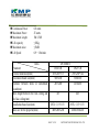
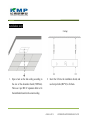
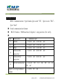
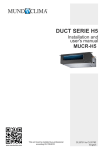
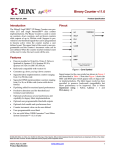
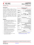
Users’ Manual DS series Projector Motorized Lift PAGE: 1 OF 19 COPY RIGHT: KMP TECHNOLOGY CO. LTD Safety precautions: Please read this “safety precautions” carefully before using the projector lifts to ensure of the correct and safety using way. The warnings protect the human and property’s safe. The following signs indicated what level of the danger and damage you will be suffer if not comply the “safety precautions” DANGER DANGER indicate the incorrect operation will cause the serious accident. WARNING WARNING indicate the incorrect operation will cause the serious accident. CAUTION CAUTION indicate the incorrect operation will cause the serious accident. Prohibited Prohibited operation。 Compulsory Compulsory operation。 PAGE: 2 OF 19 COPY RIGHT: KMP TECHNOLOGY CO. LTD Disassembly Prohibited Disassembly is Prohibited。 Remove Power plug Remove Power plug。 DANGER Must install the lift comply with this manual strictly. Replace the spare parts by other factories is prohibited. Please don’t amend or modify the electric board or change the components without our factory ‘s permission ,or it will cause the motor accident or control failure, lead to the wire breaking ,ceiling damage, projector falling etc. CAUTION Please don’t use it under the condition of high temperature, wet and dirty . Don’t use the wireless in the high interference. Compulsory Try not to use an unstable power supply, to make sure the voltage is stable when using the auxiliary power. PAGE: 3 OF 19 Prohibited Prohibited COPY RIGHT: KMP TECHNOLOGY CO. LTD WARNING Over load capacity is prohibited. Don’t make it up and down frequently to prevent fire the motor. Please don’t install or adjust the lift without the professional worker . Prohibited Prohibited Please don’t disassembled the lift without permission, it should be maintained and amended by professional worker. And can’t the instruction of the lift. Please cut off the power when across the accident. PAGE: 4 OF 19 Disassembly Prohibited Remove Power plug COPY RIGHT: KMP TECHNOLOGY CO. LTD Contents Introduction Features parameter Product usage Installation requirement Installation steps Cable routing instruction Projector adjusting steps Attention points Troubleshooting Communication setting PAGE: 5 OF 19 COPY RIGHT: KMP TECHNOLOGY CO. LTD Introduction : Features: Adopt the latest micro-computer control system ,intelligent and stable; Double power breakdown protection equipped with the audible alarm, Make the damage to the lowest by the accident; Multiple control methods combined various center control; Easy to adjust the running distance of the lift, stop position accurately. High position accuracy up to 1 mm; Originate the machine without demounting when installation or adjustment. Easy to maintain; Reasonable instruction with the high quality material, handsome Exterior. Introduction : Parameter: Voltage Frequency Peak load current 220V~ 50/60Hz 0.15A PAGE: 6 OF 19 COPY RIGHT: KMP TECHNOLOGY CO. LTD Continuous Power Maximum Power Maximum Length Lift capacity Maximum noise Lift Speed 0.8 watts 25 watts 1M/1.5M/ ≤10Kg ≤50dB 0.9~1.8m/min Items Parameter Exterior dimension(mm) Decoration board size(mm) Distance between holes in installation board(mm) Mini height between the real ceiling and the fake ceiling(mm) Installation board size(mm) Max size for the projector(mm) DS SERIES DS210-R DS215-R 285X266*115 285X266*142 500X500 500X500 245X400 245X400 415 445 265X(115+115) 400X380X200 265X(115+115) 400X380X200 PAGE: 7 OF 19 COPY RIGHT: KMP TECHNOLOGY CO. LTD Distance(mm) Load capacity(kg) N.W(kg) Power(W) Rated voltage AC(V) R/C Electric stop position 1000 10 14 20 220V W W 1500 10 15 20 220V W W Installation requirements: The height between the cement ceiling and fake ceiling must more than: projector height+ universal head height +projector height. Except special circumstance. Suggested ceiling open size:600mmX600mm (Base on the projector size) The open hole suggested set out at the distance of 100-200mm away from projector ,Open size:500*400mm PAGE: 8 OF 19 COPY RIGHT: KMP TECHNOLOGY CO. LTD There are four screw holes (13mm*58mm) in the top panel of the lift, use the anchoring screw (φ8mm~φ10mm), Fixing the lift to the cement ceiling. Confirm the install poison of the cement ceiling, and make holes in the ceiling based on the screws. The anchoring screw must be set deeply into the ceiling to ensure the enough load capacity. Install avoid the warm equipment, for example the steam pipe, warm-air pipe. The power equipment must have a 5A circuit breaker. The copper cable cross-sectional area of the power must not less than 1.5mm. It should have a good ground cable, the resistance must not bigger than 4Ω. Use the CAT-5 as the extend control wire. PAGE: 9 OF 19 COPY RIGHT: KMP TECHNOLOGY CO. LTD Installation step: (Ceiling) 1. Open a hole on the fake ceiling according to the size of the decoration board (50X50cm). Then use 4 pcs M8×12 expansion bolts to fix the installation board on the cement ceiling. 2. Insert the lift into the installation board, and use four pcs bolts (M6*12) to fix them. PAGE: 10 OF 19 COPY RIGHT: KMP TECHNOLOGY CO. LTD 4. Install the universal head and claws to fix the projector. 3. Insert the lift into the installation board, and use four pcs bolts (M6*12) to fix them. 。 PAGE: 11 OF 19 COPY RIGHT: KMP TECHNOLOGY CO. LTD 5,Install decoration board and adjust the screw poles to make the decoration board keep parallel with the fake ceiling. (Ceiling) PAGE: 12 OF 19 COPY RIGHT: KMP TECHNOLOGY CO. LTD Bind line point Bind line point Bind line point (Before binding the wires, please have the lift down to the projector working position) PAGE: 13 OF 19 COPY RIGHT: KMP TECHNOLOGY CO. LTD Stop position setting step: Projection position setting : Press the eight key remote controller key 8, The lift will move down to the general projection position, relax the key 8, and press 8 (down) or key 7 (up) lightl y to adjust the right projection position. Press key 6 till hear the beep sound project, it means the down position setting successful. Backing position setting: Press the key 7 on remote controller key, The projector will move up to the ceiling, relax the key 7, and press 8 (down) or key 7 (up) lightl y to adjust the right backing position , Press key 5till hear the beep sound, it means the up position setting successful. PAGE: 14 OF 19 COPY RIGHT: KMP TECHNOLOGY CO. LTD Key instruction: Key name Action Lift 1 升(Up)/2 降(Down) Touch control The projector move up or down to the right projection area. 4 停(Stop) Touch control 5 升存(Up saved) / 6 Long time press Save the position. Touch control Adjust the position Eight -key remote controller Three–key remote 降存(Down saved) for projector set up control for end user 7 点动升 (Up)/8(Down) 的八键遥控器 Stop the projection at any place. 点动降 7 点动升/8 点动降 Long time press Touch the key, the lift will keep moving until releasing. Remark: The position saved successfully when heard the feedback voice from the lift. Troubleshooting Please call us for permission of customers’ self service on the projector lifts if the newly installed or used products break down. Otherwise, unauthorized service will render the warranty void. Check the grounded protection to make sure of security in avoidance of electric shock accident. PAGE: 15 OF 19 COPY RIGHT: KMP TECHNOLOGY CO. LTD 1. 2. 1. 2. 3. After the lift power on, if press the operation button but the lift does not go upward or downward, please check it as following steps: check to confirm whether the fuse be burned broken, if yes, please replace it with new 2A fuse. check to confirm whether the power wires be connected well, and whether the power in good status. Thoroughly no response, no movement at all stop operation for over 15 minutes then restart, to find out whether the lift is in the overheated status. Check and confirm whether the power wire end is live, and whether the voltage is OK. If it is not live please check whether the power circuit is OK. If the power wire and end are OK, please check whether the connection between the wires and the engine are loose and disconnected, and whether the fuse be burned broken, and whether the wire connection of the upwards stopping switch and downwards stopping switch are loosed and disconnected. If need to disassemble the the lift for repairing, please lie down the lift, draw the lift apart (in level), then use screwdriver to open the top cover and take the repair. The lift do not move when press neither the upwards button or the downwards button, but can hear the weak shocking sound. PAGE: 16 OF 19 COPY RIGHT: KMP TECHNOLOGY CO. LTD Please check whether the capacitor be hit through, or short circuit, and whether the wire connection is loosed and broken. At the meaning time, the engine will be overheated, you should shut down the power immediately to avoid the engine being burned, and then to check whether the capacitor is OK. Can hear weak shocking sound when the lift runs upwards and reaches the up end. Please check whether the upwards stopping position switch is OK. when the lift moves downwards and reaches the down end, the engine does not stop working but keeps rotating, and make the lift be up again.Please check whether the downward stopping position switch is OK. The lift do not move when press neither the upward or downward button, but it makes big noise. 1. please check whether the transmission gear is blocked by other object, or broke. 2. check whether the teeth of the gears do not meet each other. The lift is not in balance or joggle when it move upwards or downwards. 1. please check whether the rolling belts are rolled neatly and orderly on the rolling axis. 2. please check whether the 2 pcs of rolling belts are in the same force density. 3. please check whether the connecting screws between the crossing scissors are loose or disconnected. PAGE: 17 OF 19 COPY RIGHT: KMP TECHNOLOGY CO. LTD Communication: RS232 communication :9 pin female,2pin send “TX” ,3pin receive ”RX”, 5pin “Gnd” Serial communicati on format: RS232 format; 9600baud rate,8 digital, 1 stop position ,No verify. No. 1 2 3 4 5 6 Instruction Down Up Stop Turn on the projector Turn off the projector Set ID instruction Right receiving feedback format Instruction code CA 20 ID 21 CA 20 ID 21 CA 20 ID 21 CA 20 ID 20 CA 20 ID CA 20 ID AC CA 90 02 01 00 00 AC AC AC AC 20 01 01 AC FE FF 01 01 01 01 CC 04 00 10 01 A6 PAGE: 18 OF 19 COPY RIGHT: KMP TECHNOLOGY CO. LTD Fault receiving feedback format ID setting level : Broadcast ID: CA 80 FF B6 00 – C0 F0 (Need to restart the machine after setting the I D. PAGE: 19 OF 19 COPY RIGHT: KMP TECHNOLOGY CO. LTD