1
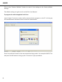
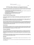
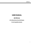
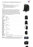
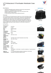
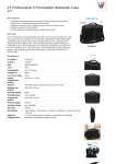
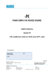
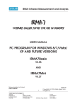
LAN232 USER MANUAL LAN232 LAN232 Trio Serial to Ethernet Converter Synectix LLC. 291-A, Pepes Farm Road, Milford, CT-06460 www.synectix.net 1 LAN232 LAN232 / LAN232 Trio User Manual Edition Firmware Version LAN232 LAN232 Trio January 2013 5.00 5.00 All specifications, information contained herein is subject to change without prior notice. Notice: Please read this manual thoroughly before operating the unit and retain it for future reference. To prevent fire or shock hazard, do not expose this unit to rain or moisture. To avoid electrical shock refer servicing of this product to the dealer from whom the purchase was made. No user serviceable parts inside. Static Discharge Warning : The discharge of electrostatic energy that accumulates on the surface of human body or other surfaces can disrupt the working of the unit or damage the electronic components inside the unit. Observe static safe procedures while handling, installing and maintaining the unit. On Static discharge the unit may experience temporary loss of function, which may require that the unit be powered off and then on to restore normal functioning. Synectix LLC. 291-A, Pepes Farm Road, Milford, CT-06460 Email : [email protected] 2 LAN232 Specifications Power Indicators Serial Port Baud rate Ethernet port Config Switch 9 VAC, 2W LED for Power, Link, Active for Ethernet port Tx, Rx for Serial port LAN232 : One LAN232 Trio : Three 300 to 115200 bps 10/100 Mbps. Link, Active LED’s Auto MDI/MDIX, UPnP protocol supported To program the unit using Serial Port General Features The LAN232 family of products is available in Single port and 3 port (LAN232 Trio) versions. All the features are common between these two models except for the different number of ports being available on them. The LAN232 family of products is Serial to Ethernet converters which are very easy to install and use and supports baud rates from 300 to 115200 bauds on the serial ports. The unit works in the Client mode - where the unit initiates a connection on the Ethernet port - or the Server mode where it waits for the connection to be made by a client. All data received on the Serial port is transmitted to the Ethernet port and vice versa. If data is received through the Serial port while there is no active connection on the Ethernet port, then all such data will be lost. The LAN232 units are fully programmable through the Network port and support the UPnP protocol. Installation Unpack the unit from its shipping carton and check that all the materials have been received in good condition. Any damages or shortfalls must be reported immediately to the distributor from whom the purchase was made. Your LAN232 shipping carton must contain the following: The LAN232 / LAN232 Trio Unit Power Adapter Ethernet cable 3 LAN232 Select a suitable location for the unit to be placed. A suitable location should have a power socket close by and should be easily accessible for any service or maintenance work. Plug in the Power Adaptor into the Power socket, connect the Serial port on the PC to the unit, plug in the Ethernet cable into the socket on the unit and the other end of the cable into the LAN port. Switch on the power to the unit and the Power lamp starts blinking after a few seconds. The unit waits for a Serial Port programming request for 1 minute after power up and then enters the Network mode. If a valid Network connection is present, the Link lamp starts glowing and the Active lamp will blink a few times while the unit acquires an IP address for itself from the Server if DHCP is enabled on the unit. All the screen views shown are for the LAN232 Trio unit. However, these views would be identical for the single port LAN232 also except that Serial Port 2 and 3 will not be present. Programming the unit through the Network port : Once the unit is powered up, it initiates Network Discovery with the Universal Plug-andPlay protocol and automatically establishes its working configuration with other devices on the network. If your computer is set up with the Network Discovery enabled and if the LAN232 unit either acquires or has an IP address in the same range as the rest of the units on the network, then the unit would appear as shown below : The UPnP discovery protocols are normally enabled in Windows Vista and Windows 7, whereas it may need to be enabled in Windows XP. 4 LAN232 Windows XP : To enable the UPnP Interface, go to the Control Panel and open the “Add or Remove Programs”, select the Windows components option, click the check box for `Network Services’ and then enable the UPnP Interface option in the pop up box. Windows Vista : To enable the Network discovery option, go to the Control Panel, open the Network and Sharing center and then enable the Network Discovery option as shown below. Windows 7 : To enable the Network discovery option, go to the Control Panel, open the Network and Sharing center and in the Advanced sharing settings option turn on the Network Discovery option as shown below. 5 LAN232 Note : The LAN232 unit would always be visible in the network if the unit is in DHCP mode (default mode) or if the unit has been previously set to a Static IP address which is in the same sub net as the rest of the network. However, if the unit has been previously set to a Static IP address which is NOT in the same sub net as the rest of the network, then the unit would not be visible in the network and you will not be able to access the unit through your browser. In such a case, you will need to change the unit’s IP address or to DHCP mode using the Serial port programming option as described later in this Manual. Once the unit is visible on the network, note its IP address, simply type this IP address in the browser’s address bar and press Enter to communicate with the unit. The unit responds to the browser’s request and the information is displayed as shown below. The settings for Serial Port 1 would be displayed and you may change any of the settings and then press the “Submit” button to save the settings. 6 LAN232 Click on the hyperlink for Serial Port 2 or Serial Port 3 to view and / or change their settings. Click on the “Click for IP settings” hyperlink at the bottom of the information box to view or change its IP settings. The information box will show the MAC Address of the unit and you may change the unit’s IP address type from Static to Dynamic or vice versa. 7 LAN232 Click on the “Restore Defaults” button to reset all the settings to the factory default settings. The default settings are given at the end of this User Manual. To program the unit through the Serial Port : Launch Hyper Terminal or other similar communication program on the PC to bring up the communication window similar to the one shown below. Enter the preferred name for the new connection being made – for example LAN232 Trio and press the OK button to bring up the “Connect to” pop up window. 8 LAN232 Click on the drop down menu bar for the “Connect using” option, select the COM port to which the unit is connected and set the parameters to 9600 baud, N,8,1 and None for Flow Control as shown below. Clicking the Restore defaults button would also set it to these default parameters. Click the Apply button and then the OK button. Press the CONFIG switch on the unit and the current parameters are transmitted out on the serial port which may be seen in the Hyper Terminal screen. 9 LAN232 Note : To exit out of the programming mode, press Z to Save the settings and exit or press ESC key to exit without saving. If the Z or the ESC key is not pressed, the unit will remain in the programming mode. The LAN232 units use a fixed baud rate of 9600, 8, N, 1, No flow control during the programming mode and will revert to the baud rate programmed in the unit for the Data mode of operation. Note : The LAN232 Trio unit may be programmed using the port marked as Serial 3 only. The current program parameters of the LAN232 are displayed along with the options for changing the various parameters. To change a parameter, press the corresponding character. The available options are displayed on the HyperTerminal window. The LAN232 has options 1 to 4 and A to K available, whereas the LAN232 Trio has options 1 to 7 and A to K as shown below. To change the baud rate of the serial port, press A and you will now be shown the available options for the different baud rates. Now press the desired digit to set the required baud rate. For example, press digit 2 to set 1200 as the baud rate for the serial port. 10 LAN232 Use options 1 to 4 to change the IP settings. Use options 5 for Serial Port 1 settings, option 6 for Serial Port 2 settings and option 7 for Serial Port 3 settings. Press Z to save the settings. Note : 1. 2. 3. The serial ports on the LAN232 units emulate the RS232 DCE interface and have DB9 Female connectors. Use a straight cable between the LAN232 and the PC. When in the programming mode, the unit does not time out and will remain in the programming mode until you press the Escape key to exit or the Z key to save and exit. The Ethernet ports of the LAN232 units support the TCP Client and Server modes of operation. These modes are described below. TCP Server mode : The Ethernet port of the LAN232 unit acts like a device server which waits passively to be contacted by a host (the host plays the role of Client). Once a connection has been established, the host computer can receive and transmit data to and from the serial device. This mode is typically required to be used when the LAN232 is used for remote log in purposes. TCP Client mode : The Ethernet port of the LAN232 unit acts like a client which actively contacts one or more hosts (the hosts play the role of Server). Once a connection has been established, the hosts can receive and transmit data to and from the serial device. This mode is typically required to be used when the LAN232 is used between a PMS system (which sends data out on the serial port to the PBX and the Voice Mail System) and a phone system (which needs the data to arrive on its Ethernet port) 4. DHCP Enable / Disable : Select the DHCP Disable option to assign a specific IP address to the LAN232 unit. Select the DHCP Enable option if you want the unit to acquire an IP address from the DHCP Server in the local network. Typical Default settings : IP Address Subnet mask Gateway Remote IP DHCP = 192.168.1.5 (for LAN232) = 192.168.1.7 (for LAN232 Trio) = 255.255.255.0 = 192.168.1.2 = 192.168.1.2 = Disable Serial port 1 = 9600, N, 8, 1, Client mode, port 61320 Serial port 2 = 1200, E, 7, 1, Client mode, port 6830 Serial port 3 = 1200, N, 8, 1, Telnet Client mode, port 61328 11 LAN232 Statutory Information FCC Information: This equipment has been tested and found to comply with the limits for a Class B digital device, pursuant to Part 15 of the FCC rules. These limits are designed to provide reasonable protection against harmful interference in a residential installation. This equipment generates, uses and can radiate radio frequency energy and, if not installed and used in accordance with the instructions, may cause harmful interference to radio communications. However, there is no guarantee that interference will not occur in a particular installation. If this equipment does cause harmful interference to radio or television reception, which can be determined by turning the equipment off and on, the user is encouraged to try to correct the interference by one or more of the following measures: Reorient or relocate the receiving antenna. Increase the separation between the equipment and the receiver. Connect the equipment into an outlet on a circuit different from that to which the receiver is connected. Consult the dealer or an experienced technician for help. You are cautioned that any changes or modifications not expressly approved in this manual could void your authority to operate this equipment. Caution: This unit should not be connected to or installed directly on a PSTN or any other Public, Government or Private Telecommunication Network which is in violation of any certification or Registration requirements of any State or Central Law or Act or is in contravention of any of the provisions of the local regulations. All direct, indirect and consequential liabilities arising out of the failure to comply with the above instruction is the sole responsibility of the user only. Limited Warranty : See the Limited Warranty Card supplied along with this unit for details. Shipping the unit for repairs during or after the warranty period: Before shipping ensure that the product is packed in either the original shipping carton or in a wellpadded, heavy duty corrugated box to prevent damage to the unit in transit. Enclose a copy of your sales invoice (proof of purchase) and ship the unit freight prepaid and insured for a replacement value. 12