1
Std_DevelopersKit
User’s Manual
Version 2.2
Copyright Mentor Graphics Corporation 1996-1997. All rights reserved.
This document contains information that is proprietary to Mentor Graphics Corporation and may be
duplicated in whole or in part by the original recipient for internal business purposes only, provided that this
entire notice appears in all copies. In accepting this document, the recipient agrees to make every
reasonable effort to prevent the unauthorized use of this information.
The software programs described in this document are confidential and proprietary products of Mentor
Graphics Corporation (Mentor Graphics) or its licensors. No part of this document may be photocopied,
reproduced or translated, or transferred, disclosed or otherwise provided to third parties, without the
prior written consent of Mentor Graphics.
The document is for informational and instructional purposes. Mentor Graphics reserves the right to
make changes in specifications and other information contained in this publication without prior notice,
and the reader should, in all cases, consult Mentor Graphics to determine whether any changes have
been made.
The terms and conditions governing the sale and licensing of Mentor Graphics products are set forth in
the written contracts between Mentor Graphics and its customers. No representation or other affirmation
of fact contained in this publication shall be deemed to be a warranty or give rise to any liability of Mentor
Graphics whatsoever.
MENTOR GRAPHICS MAKES NO WARRANTY OF ANY KIND WITH REGARD TO THIS MATERIAL
INCLUDING, BUT NOT LIMITED TO, THE IMPLIED WARRANTIES OR MERCHANTABILITY AND
FITNESS FOR A PARTICULAR PURPOSE.
MENTOR GRAPHICS SHALL NOT BE LIABLE FOR ANY INCIDENTAL, INDIRECT, SPECIAL, OR
CONSEQUENTIAL DAMAGES WHATSOEVER (INCLUDING BUT NOT LIMITED TO LOST PROFITS)
ARISING OUT OF OR RELATED TO THIS PUBLICATION OR THE INFORMATION CONTAINED IN IT,
EVEN IF MENTOR GRAPHICS CORPORATION HAS BEEN ADVISED OF THE POSSIBILITY OF
SUCH DAMAGES.
RESTRICTED RIGHTS LEGEND Use, duplication, or disclosure by the Government is subject to
restrictions as set forth in the subdivision (c)(1)(ii) of the Rights in Technical Data and Computer
Software clause at DFARS 252.227-7013.
A complete list of trademark names appears in a separate “Trademark Information” document.
Mentor Graphics Corporation
8005 S.W. Boeckman Road, Wilsonville, Oregon 97070-7777.
This is an unpublished work of Mentor Graphics Corporation.
Table of Contents
TABLE OF CONTENTS
About This Manual ...............................................................................................xv
Introduction...........................................................................................................xv
Contents ...............................................................................................................xvi
Chapter 1
Std_IOpak ............................................................................................................ 1-1
Using Std_IOpak ................................................................................................ 1-1
Command Summary ........................................................................................... 1-1
String Conversion............................................................................................. 1-1
String Functions ............................................................................................... 1-2
File I/O and Text Processing............................................................................ 1-2
String Definition............................................................................................... 1-2
ASCII_TEXT ................................................................................................... 1-3
Function Dictionary ............................................................................................ 1-4
From_String ..................................................................................................... 1-5
From_String (boolean) .................................................................................... 1-7
From_String (bit) ............................................................................................ 1-8
From_String (severity_level) .......................................................................... 1-9
From_String (character) ................................................................................ 1-11
From_String (integer).................................................................................... 1-12
From_String (real)......................................................................................... 1-13
From_String (time)........................................................................................ 1-15
From_String (std_ulogic) .............................................................................. 1-17
From_String (std_ulogic_vector) .................................................................. 1-19
From_String (std_logic_vector) .................................................................... 1-21
From_BinString.............................................................................................. 1-23
From_OctString.............................................................................................. 1-25
From_HexString............................................................................................. 1-27
To_String........................................................................................................ 1-29
To_String (boolean) ...................................................................................... 1-34
To_String (bit)............................................................................................... 1-37
To_String (character) .................................................................................... 1-40
To_String (severity_level) ............................................................................ 1-44
To_String (integer)........................................................................................ 1-47
Std_DevelopersKit User’s Manual, V2.2
iii
Table of Contents
TABLE OF CONTENTS [continued]
To_String (real) ............................................................................................. 1-50
To_String (time)............................................................................................ 1-53
To_String (bit_vector)................................................................................... 1-56
To_String (std_ulogic) .................................................................................. 1-60
To_String (std_logic_vector) ......................................................................... 1-62
To_String (std_ulogic_vector) ...................................................................... 1-65
Is_Alpha ......................................................................................................... 1-68
Is_Upper ......................................................................................................... 1-69
Is_Lower ........................................................................................................ 1-70
Is_Digit........................................................................................................... 1-71
Is_Space ......................................................................................................... 1-72
To_Upper (one ASCII char).......................................................................... 1-73
To_Upper (all ASCII chars).......................................................................... 1-74
To_Lower (one ASCII char) ......................................................................... 1-75
To_Lower (all ASCII chars) ......................................................................... 1-76
StrCat.............................................................................................................. 1-77
StrNCat........................................................................................................... 1-78
StrCpy ............................................................................................................ 1-80
StrNCpy.......................................................................................................... 1-81
StrCmp ........................................................................................................... 1-83
StrNCmp ........................................................................................................ 1-86
StrNcCmp....................................................................................................... 1-89
StrLen............................................................................................................. 1-92
Copyfile (ASCII_TEXT) .............................................................................. 1-93
Copyfile (TEXT) ........................................................................................... 1-94
fprint (to ASCII_TEXT file) ......................................................................... 1-95
fprint (to TEXT file)...................................................................................... 1-99
fprint (to string_buf).................................................................................... 1-103
fscan (from ASCII_TEXT file) ................................................................... 1-107
fscan (from TEXT file) ................................................................................ 1-112
fscan (from string_buf) ............................................................................... 1-117
fgetc (ASCII_TEXT) .................................................................................. 1-122
fgetc (TEXT) ............................................................................................... 1-123
fgets (ASCII_TEXT)................................................................................... 1-124
fgets (TEXT) ............................................................................................... 1-126
iv
Std_DevelopersKit User’s Manual, V2.2
Table of Contents
TABLE OF CONTENTS [continued]
fgetline (ASCII_TEXT) .............................................................................. 1-128
fgetline (TEXT)........................................................................................... 1-130
fputc (ASCII_TEXT) .................................................................................. 1-132
fputc (TEXT)............................................................................................... 1-133
fputs (ASCII_TEXT) .................................................................................. 1-134
fputs (TEXT) ............................................................................................... 1-135
Find_Char..................................................................................................... 1-136
Sub_Char...................................................................................................... 1-137
Chapter 2
Std_Mempak........................................................................................................ 2-1
Using Std_Mempak ............................................................................................ 2-1
Referencing the Std_Mempak Package ........................................................... 2-2
Known Discrepancies ......................................................................................... 2-2
Introduction......................................................................................................... 2-2
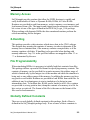
Memory Access................................................................................................ 2-3
X-Handling....................................................................................................... 2-3
File Programmability ....................................................................................... 2-3
Globally Defined Constants ............................................................................. 2-3
General Information............................................................................................ 2-4
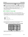
Video RAM Support ........................................................................................ 2-5
Refreshing of DRAMs and VRAMs ................................................................ 2-6
Dynamic Allocation ......................................................................................... 2-6
Row and Column Organization........................................................................ 2-6
Subroutines....................................................................................................... 2-7
X-Handling....................................................................................................... 2-8
ROMs................................................................................................................ 2-10
ROM_Initialize .............................................................................................. 2-11
Static RAMs...................................................................................................... 2-13
SRAM_Initialize ............................................................................................ 2-14
Dynamic RAMs ................................................................................................ 2-16
DRAM_Initialize............................................................................................ 2-18
Mem_Wake_Up ............................................................................................. 2-21
Mem_Refresh ................................................................................................. 2-22
Mem_Row_Refresh ....................................................................................... 2-23
Std_DevelopersKit User’s Manual, V2.2
v
Table of Contents
TABLE OF CONTENTS [continued]
Mem_Access .................................................................................................. 2-25
Video RAMs ..................................................................................................... 2-29
General Information ....................................................................................... 2-29
VRAM_Initialize............................................................................................ 2-37
Mem_Set_WPB_Mask................................................................................... 2-41
Mem_Block_Write......................................................................................... 2-43
Mem_Row_Write........................................................................................... 2-48
Mem_RdTrans................................................................................................ 2-52
Mem_Split_RdTrans ...................................................................................... 2-57
Mem_RdSAM ................................................................................................ 2-63
Mem_Split_RdSAM ...................................................................................... 2-65
Mem_WrtTrans .............................................................................................. 2-67
Mem_Split_WrtTrans .................................................................................... 2-72
Mem_WrtSAM .............................................................................................. 2-78
Mem_Split_WrtSAM..................................................................................... 2-80
Mem_Get_SPtr............................................................................................... 2-82
Mem_Set_SPtr ............................................................................................... 2-84
To_Segment ................................................................................................... 2-86
Mem_Active_SAM_Half ............................................................................... 2-88
Common Procedures......................................................................................... 2-89
Mem_Read ..................................................................................................... 2-91
Mem_Write .................................................................................................... 2-95
Mem_Reset .................................................................................................. 2-100
Mem_Load ................................................................................................... 2-103
Mem_Dump ................................................................................................. 2-105
Mem_Valid .................................................................................................. 2-107
Memory Files.................................................................................................. 2-109
File Format ................................................................................................... 2-109
Sample Memory File.................................................................................... 2-111
Memory Models.............................................................................................. 2-113
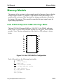
Intel 21010-06 Dynamic RAM with Page Mode ......................................... 2-113
INTEL 51256S/L-07 Static RAM................................................................ 2-121
INTEL 2716 EPROM .................................................................................. 2-131
vi
Std_DevelopersKit User’s Manual, V2.2
Table of Contents
TABLE OF CONTENTS [continued]
Chapter 3
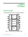
Std_Regpak .......................................................................................................... 3-1
Using Std_Regpak .............................................................................................. 3-1
Referencing the Std_Regpak Package ............................................................. 3-2
Introduction......................................................................................................... 3-2
Overloaded Built-In Functions......................................................................... 3-2
Arithmetic and Logical Functions.................................................................... 3-3
Conversion Functions....................................................................................... 3-4
Globally Defined Constants ............................................................................. 3-4
Selecting the Arithmetic Data Representation ................................................. 3-4
Selecting the Level of Error Checking............................................................. 3-5
Setting the System’s Integer Length ................................................................ 3-5
Vector Parameters ............................................................................................ 3-6
Function Dictionary ............................................................................................ 3-7
Function Summary ........................................................................................... 3-7
abs .................................................................................................................. 3-11
+...................................................................................................................... 3-13
- (Unary Operator)........................................................................................ 3-16
- (binary operator) ......................................................................................... 3-19
*...................................................................................................................... 3-22
/....................................................................................................................... 3-25
mod................................................................................................................. 3-29
rem.................................................................................................................. 3-33
**.................................................................................................................... 3-37
=...................................................................................................................... 3-39
/= .................................................................................................................... 3-43
>...................................................................................................................... 3-47
>= ................................................................................................................... 3-51
<...................................................................................................................... 3-55
<= ................................................................................................................... 3-59
ConvertMode.................................................................................................. 3-63
RegAbs........................................................................................................... 3-65
SRegAbs......................................................................................................... 3-67
RegAdd .......................................................................................................... 3-69
Std_DevelopersKit User’s Manual, V2.2
vii
Table of Contents
TABLE OF CONTENTS [continued]
SRegAdd ........................................................................................................ 3-72
RegDec ........................................................................................................... 3-75
RegDiv ........................................................................................................... 3-77
SRegDiv ......................................................................................................... 3-81
RegEqual ........................................................................................................ 3-85
RegExp........................................................................................................... 3-91
SRegExp......................................................................................................... 3-93
RegFill............................................................................................................ 3-95
RegGreaterThan ............................................................................................. 3-97
RegGreaterThanOrEqual.............................................................................. 3-102
RegInc .......................................................................................................... 3-107
RegLessThan................................................................................................ 3-109
RegLessThanOrEqual .................................................................................. 3-114
RegMod........................................................................................................ 3-119
SRegMod...................................................................................................... 3-123
RegMult........................................................................................................ 3-127
SRegMult ..................................................................................................... 3-130
RegNegate .................................................................................................... 3-133
RegNotEqual ................................................................................................ 3-135
RegRem........................................................................................................ 3-140
SRegRem...................................................................................................... 3-144
RegShift........................................................................................................ 3-148
SRegShift ..................................................................................................... 3-152
RegSub ......................................................................................................... 3-156
SRegSub....................................................................................................... 3-159
SignExtend ................................................................................................... 3-162
To_BitVector................................................................................................ 3-165
To_Integer .................................................................................................... 3-167
To_OnesComp ............................................................................................. 3-169
To_SignMag................................................................................................. 3-171
To_StdLogicVector...................................................................................... 3-173
To_StdULogicVector ................................................................................... 3-175
To_TwosComp............................................................................................. 3-177
To_Unsign.................................................................................................... 3-179
viii
Std_DevelopersKit User’s Manual, V2.2
Table of Contents
TABLE OF CONTENTS [continued]
Chapter 4
Std_Timing........................................................................................................... 4-1
Introduction......................................................................................................... 4-1
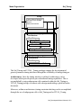
Model Organization ............................................................................................ 4-1
Passing Timing Information into a circuit of VHDL models .......................... 4-3
Referencing the Std_Timing and VITAL_Timing Package ............................ 4-5
Model Interface Specification............................................................................. 4-6
General Philosophy .......................................................................................... 4-6
Model Entity Development Guidelines............................................................ 4-7
Generic Parameters .......................................................................................... 4-9
BaseIncrToTime............................................................................................. 4-22
BaseIncrToMinTypMaxTime ........................................................................ 4-23
Hierarchical Pathname...................................................................................... 4-24
Port Declarations ............................................................................................ 4-24
Interconnect Modeling...................................................................................... 4-26
Simple Unidirectional Single Driver-Multiple Receiver Topology............... 4-26
VitalPropagateWireDelay .............................................................................. 4-28
AssignPathDelay ............................................................................................ 4-30
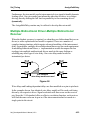
Multiple Driver-Multiple Receiver ................................................................ 4-32
Multiple Bidirectional Driver-Multiple Bidirectional Receiver .................... 4-33
Back-Annotation............................................................................................... 4-34
Mechanism for passing timing data ............................................................... 4-36
Derating of Timing Values............................................................................. 4-38
DeratingFactor................................................................................................ 4-43
DerateOutput .................................................................................................. 4-45
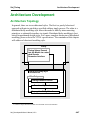
Architecture Development................................................................................ 4-47
Architecture Topology ................................................................................... 4-47
Timing Violation Section............................................................................... 4-49
SetupViolation................................................................................................ 4-52
SetupCheck .................................................................................................... 4-54
HoldViolation................................................................................................. 4-56
HoldCheck...................................................................................................... 4-58
VitalTimingCheck.......................................................................................... 4-60
VitalSetupHoldCheck .................................................................................... 4-67
Std_DevelopersKit User’s Manual, V2.2
ix
Table of Contents
TABLE OF CONTENTS [continued]
VitalReportSetupHoldViolation..................................................................... 4-71
VitalReportRlseRmvlViolation...................................................................... 4-73
TimingViolation............................................................................................. 4-75
TimingCheck.................................................................................................. 4-78
ReleaseViolation ............................................................................................ 4-82
ReleaseCheck ................................................................................................. 4-85
VitalPeriodCheck ........................................................................................... 4-87
PeriodCheck ................................................................................................... 4-89
PulseCheck..................................................................................................... 4-92
SpikeCheck .................................................................................................... 4-93
SkewCheck..................................................................................................... 4-94
Path Delay Section ......................................................................................... 4-96
VitalCalcDelay ............................................................................................... 4-97
CalcDelay ....................................................................................................... 4-99
Drive............................................................................................................. 4-103
VitalExtendToFillDelay............................................................................... 4-104
VitalGlitchOnEvent...................................................................................... 4-105
VitalGlitchOnDetect .................................................................................... 4-107
VitalPropagatePathDelay ............................................................................. 4-109
MAXIMUM ................................................................................................. 4-112
MINIMUM................................................................................................... 4-113
Std_SimFlags - a “UserDefinedTimingDataPackage” ................................... 4-114
Std_SimFlags ............................................................................................... 4-114
Index
x
Std_DevelopersKit User’s Manual, V2.2
Table of Contents
LIST OF FIGURES
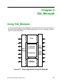
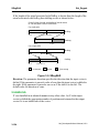
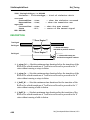
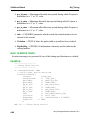
Figure 2-1. Three-stage Model Using Std_Mempak ......................................... 2-1
Figure 2-2. ‘U’ and ‘X’ Handling of Input Data ............................................... 2-8
Figure 2-3. ‘U’ and ‘X’ Handling of Addresses ................................................ 2-9
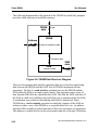
Figure 2-4. VRAM Data Structure Diagram ................................................... 2-30
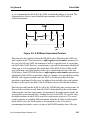
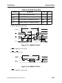
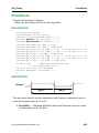
Figure 2-5. A SAM and Associated Pointers................................................... 2-31
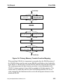
Figure 2-6. Primary Memory Transfer Function Mapping.............................. 2-35
Figure 2-7. Dynamic Allocation of Std_Mempak ........................................... 2-89
Figure 2-8. Mem Load and Mem Dump Procedures ....................................... 2-89
Figure 2-9. Intel 21010-06 Pin Configuration ............................................... 2-113
Figure 2-10. Model Intel 21010-06 Using Std_Mempak Subroutines .......... 2-116
Figure 2-11. READ CYCLE 2....................................................................... 2-123
Figure 2-12. READ CYCLE 3....................................................................... 2-123
Figure 2-13. Write Cycle 1 ............................................................................ 2-124
Figure 2-14. Write Cycle 2 ............................................................................ 2-124
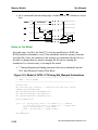
Figure 2-15. Model of INTEL 51256S/L-07 Static RAM Using Std_Mempak
Subroutines ..................................................................................................... 2-125
Figure 2-16. Model of INTEL 2716 Using Std_Mempak Subroutines ......... 2-132
Figure 3-1. Three-stage Model and Applicable Packages ................................. 3-1
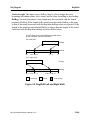
Figure 3-2. RegShift Left and Right Shift ..................................................... 3-149
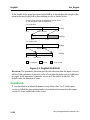
Figure 3-3. RegShift N>M Shift.................................................................... 3-150
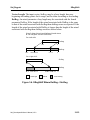
Figure 3-4. SRegShift Where DstReg < SrcReg ........................................... 3-153
Figure 3-5. SRegShift .................................................................................... 3-154
Figure 4-1. ....................................................................................................... 4-27
Figure 4-2. ....................................................................................................... 4-33
Figure 4-3. ....................................................................................................... 4-35
Figure 4-4. ....................................................................................................... 4-54
Figure 4-5. ....................................................................................................... 4-56
Figure 4-6. ....................................................................................................... 4-58
xi
Std_DevelopersKit User’s Manual, V2.2
Table of Contents
LIST OF FIGURES
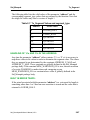
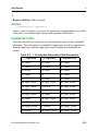
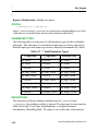
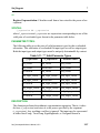
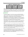
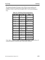
Table 1-1. Default Format String Values ........................................................ 1-32
Table 1-2. To_String(c) Resultant Output ....................................................... 1-43
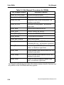
Table 2-1. Std_MemPak Globally Defined Constants ...................................... 2-4
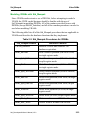
Table 2-2. Std_Mempak Procedures for VRAMs ........................................... 2-33
Table 2-3. row_segment & sam_segment for Full Size RAM ........................ 2-59
Table 2-4. row_segment & sam_segment for Half Size SAM ........................ 2-60
Table 2-5. Full Size SAM ................................................................................ 2-75
Table 2-6. Half Size SAM ............................................................................... 2-75
Table 2-7. To_Segment Values and segment_type ......................................... 2-87
Table 2-8. Bit Patterns Loaded Into Memory ................................................ 2-112
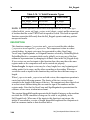
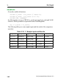
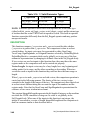
Table 2-9. Control Line Settings for 51256-07 Static RAM ......................... 2-121
Table 2-10. Read Cycle Data ......................................................................... 2-122
Table 2-11. Read Cycle Data ......................................................................... 2-131
Table 3-1. Std_Regpak Function Summary ....................................................... 3-7
Table 3-2. abs Valid Parameter Types ............................................................. 3-11
Table 3-3. ‘+’ Overloaded Subroutine Valid Parameters ................................ 3-13
Table 3-4. ‘-’ Valid Parameters ....................................................................... 3-16
Table 3-5. Examples of std_logic_vectors in Register Modes ........................ 3-17
Table 3-6. ‘-’ (binary) Valid Parameter Types ................................................ 3-19
Table 3-7. ‘*’ Valid Parameter Types ............................................................. 3-22
Table 3-8. ‘/’ Valid Parameter Types .............................................................. 3-25
Table 3-9. ‘mod’ Valid Parameter Types ........................................................ 3-29
Table 3-10. ‘rem’ Valid Parameter Types ....................................................... 3-33
Table 3-11. ‘**’ Valid Parameter Types ......................................................... 3-37
Table 3-12. ‘=’ Valid Parameter Types ........................................................... 3-39
Table 3-13. ‘=’ Comparison Results ................................................................ 3-42
Table 3-14. ‘/=’ Valid Parameter Types .......................................................... 3-43
Table 3-15. ‘/=’ Sample Inputs and Results .................................................... 3-46
Table 3-16. ‘>’ Valid Parameter Types ........................................................... 3-47
Table 3-17. ‘>’ Sample Inputs and Results ..................................................... 3-50
Table 3-18. ‘>=’ Valid Parameter Types ......................................................... 3-51
Table 3-19. ‘>=’ Sample Inputs and Results ................................................... 3-54
Table 3-20. ‘<‘ Valid Parameter Types ........................................................... 3-55
Table 3-21. ‘<‘ Sample Inputs and Results ..................................................... 3-58
Table 3-22. ‘<=’ Valid Parameter Types ......................................................... 3-59
Std_DevelopersKit User’s Manual, V2.2
xii
Table of Contents
LIST OF TABLES [continued]
Table 3-23. ‘<=’ Sample Inputs and Results ................................................... 3-62
Table 3-24. RegEqual Sample Inputs and Results ........................................... 3-90
Table 3-25. RegGreaterThan Sample Inputs and Results .............................. 3-101
Table 3-26. RegGreaterThanOrEqual Inputs and Results ............................. 3-106
Table 3-27. RegLessThan Sample Inputs and Results .................................. 3-113
Table 3-28. RegLessThanOrEqual Inputs and Results .................................. 3-118
Table 3-29. std_logic_vectors in Various Register Modes ............................ 3-134
Table 3-30. RegNotEqual Sample Inputs and Results ................................... 3-139
Table 4-1. VitalCalcDelay Assignment of Delay ............................................ 4-97
Table 4-2. CalcDelay Delay Assignments ..................................................... 4-101
Std_DevelopersKit User’s Manual, V2.2
xiii
Table of Contents
LIST OF TABLES [continued]
xiv
Std_DevelopersKit User’s Manual, V2.2
About This Manual
Introduction
This document describes the Std_DevelopersKit product for use with QuickHDL
and QuickHDL Lite. The Std_DevelopersKit product supports development of
VHDL designs. The following packages are included with the Std_DevelopersKit:
• Std_IOpak (covered in Chapter 1)
Std_IOpak provides the user with a mechanism for converting VHDL’s
built-in data types as well as the Std_logic_1164 types into strings for easy
use in file I/O and assertion statements. In addition, a number of commonly
used C language string handling functions and file I/O functions are
available to VHDL developers.
• Std_Mempak (covered in Chapter 2)
Std_Mempak provides a common interface for VHDL memory model
development. In addition, the package allows the VHDL model designer to
build a model which uses the least amount of memory space required for
the active address spaces of the memory. Using the routines provided, you
can simulate megabytes of memory system designs while using only a
fraction of the actual space on a given simulation run.
• Std_Regpak (covered in Chapter 3)
Std_Regpak consists of various arithmetic and conversion subroutines that
are designed to provide you with a wide variety of commonly implemented,
mathematical functions. This collection of procedures, functions, and
overloaded operators eliminates the need to create and verify the models for
these basic functions.
Std_DevelopersKit User’s Manual, V2.2
xv
Contents
About This Manual
• Std_Timing (covered in Chapter 4)
Helps provide accurate pin-to-pin and distributed delay within VHDL
models. In this V2.2 release of the Std_Timing package, the Std_SimFlags
package is incorporated within the Std_Timing package.
Contents
The source for VHDL packages, subroutines and functions that are shipped with
this product are contained in the directory:
<drive>:\QHDLlite\vhdl_src\sdk_src\
This source directory contains the following objects:
• iopakb.vhd--iopakp.vhd VHDL functions to support the Std_IOpak
development tools
• synthreg.vhd VHDL funtions written for design synthesis
• mempakb.vhd--mempakp,vhd VHDL routines to aid in development of
DRAMs and VRAMs
• regpakb.vhd--regpakp.vhd Arithmetic and conversion subroutines for
register development
• timingb.vhd--timingp.vhd Package for VITAL pin-to-pin and distributed
delays
• simflagb.vhd--simflagp.vhd Package defines flags to set operating
conditions for design
xvi
Std_DevelopersKit User’s Manual, V2.2
Chapter 1
Std_IOpak
Using Std_IOpak
Std_IOpak can be applied in a number of areas of a model, making Std_IOpak
very versatile. You easily reference the Std_IOpak package by making Library
and Use clause declarations.
Command Summary
Std_IOpak provides the user with a consistent mechanism for converting VHDL’s
built-in data types as well as the Std_logic_1164 types into strings for easy use in
file I/O and assertion statements. In addition, a number of commonly used C
language string handling functions and file I/O functions are available to VHDL
developers.
String Conversion
Std_IOpak provides a number of easy to use functions to convert all of the predefined VHDL types defined in package STANDARD to string types for use in
assertion messages or ASCII file I/O. In addition, Std_IOpak provides conversion
routines for the types defined in Std_logic_1164. Also provided by Std_IOpak are
functions to convert strings to these types. The following is a list of the types for
which formatted type conversion functions are provided.
1.
2.
3.
4.
5.
Boolean
Bit
Character
Severity_level
Integer
Std_DevelopersKit User’s Manual, V2.2
1-1
Command Summary
6.
7.
8.
9.
10.
11.
Std_IOpak
Real
Time
Std_ulogic
Std_ulogic_vector
Std_logic_vector
Bit_vector
String Functions
Also provided by this package are various string manipulation functions. These
are similar in nature to the most commonly used string manipulation functions
provided in the C language run time libraries. These functions provide case
conversion capabilities and comparison capabilities. Also provided are functions
for string concatenation and string copying.
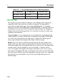
File I/O and Text Processing
Perhaps the most important capabilities provided by this package are its enhanced
file I/O procedures. File I/O is one of the most poorly defined and difficult to use
aspects of VHDL. Here functions and procedures are provided that ease the use of
file I/O. Once again, procedures similar to those found in the C language run time
libraries are provided. These subroutines handle all of the “nitty-gritty” of VHDL
file I/O and allow the user to concentrate on more important matters. The user is
provided with the ability to do formatted reads from and writes to files whose base
types are characters. For those users who need to handle I/O at a slightly lower
level, routines are provided to read and write individual characters and strings. To
allow for compatibility with the TEXTIO package, all of the subroutines provided
are overloaded to operate both on files of characters (ASCII_TEXT) and files of
TEXT.
String Definition
VHDL defines a string as an array of characters with a positive range. Alone, this
definition makes the use of strings somewhat clumsy. By overcoming this
limitation, this package allows strings to be used in a manner similar to that of the
C language. If the number of characters that the user intends to fill a string
variable with is smaller than the length of the variable itself then the character
1-2
Std_DevelopersKit User’s Manual, V2.2
Std_IOpak
Command Summary
string is terminated with a NUL character. Any future printing operations only
print the string up to the NUL character. This facilitates the use of one buffer for
strings of multiple sizes.
This package defines a new line character to be a carriage return character or a
line feed character. A white space character is defined as either a space, a tab, or a
new line character.
ASCII_TEXT
In addition to subroutines which handle files of type TEXT (a type that is predefined in the package TEXTIO), overloaded subroutines are provided to handle
the file type ASCII_TEXT. This is a type that is defined in this package to be a
file of characters. These routines can read in files that were previously written
using the TEXTIO procedures (see Known Discrepancies) but provide a more
robust way of performing file I/O. (Specifically, they avoid the need for the
additional “line_ptr” parameter that is associated with Std_IOpak routines that use
TEXT files. Also, for some simulators that support interactive I/O, that is I/O to
the screen/keyboard, ASCII_TEXT is more suited for interactive I/O than is
TEXT.)
TEXT Procedures
When using the Std_IOpak routines for TEXT files, the variable that is passed in
as the line_ptr parameter (the parameter of type LINE) must be kept in existence
for the duration of the access to the specified file. If this is not the case and the
variable is local to a function or a procedure, when the procedure is exited the
result could be a loss of data and/or a memory leak. A memory leak occurs
because the memory pointed to by the access variable is lost when the variable is
destroyed (as a result of the procedure being exited) before the memory is
explicitly deallocated. This memory leak shows up as a decrease in the available
swap space.
Globally Defined Constants
Two globally defined deferred constants, MAX_STRING_LEN and
END_OF_LINE_MARKER, are associated with this package. These constants
are defined once (at compile time) in the Std_IOpak package. Whenever these
Std_DevelopersKit User’s Manual, V2.2
1-3
Function Dictionary
Std_IOpak
constants are changed Std_IOpak must be recompiled followed by any packages
that were developed using Std_IOpak.
• MAX_STRING_LEN defines the maximum length of the strings handled
by the routines in Std_IOpak. The value of this constant at the time the
package was shipped was 256.
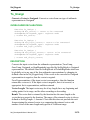
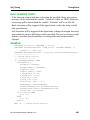
• END_OF_LINE_MARKER defines the character(s) that the routines in this
package use to determine if the end of a line has been reached when reading
information from an ASCII_TEXT file and it also determines what
character(s) they use to indicate the end of a line when writing information
to an ASCII_TEXT file. This only affects routines that access
ASCII_TEXT files or that write to string buffers. This constant is defined
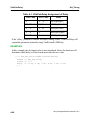
as follows:
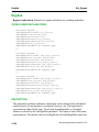
CONSTANT END_OF_LINE_MARKER : STRING(1 TO 2) := LF & ' ';
This means that the end of line marker is a line feed character (the space is
ignored). Other valid setting are:
CR & ' '
or
CR & LF
The value of this constant at the time the package was shipped is LF & ' '. It is
usually unnecessary to assign it a different value.
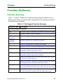
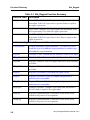
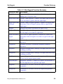
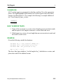
Function Dictionary
The following functions are listed in alpha-numeric order. Each function begins at
the top of a new page.
1-4
Std_DevelopersKit User’s Manual, V2.2
Std_IOpak
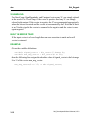
From_String
From_String
From_String is a function which converts a string to the given return type.
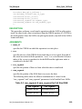
GENERAL DESCRIPTION:
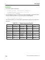
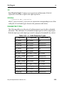
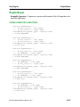
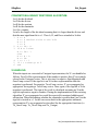
There are 13 forms of this function which include conversion to:
1.
2.
3.
4.
5.
6.
7.
8.
9.
10.
11.
12.
13.
Boolean
Bit
Severity_Level
Character
Integer
Real
Time
Std_ulogic
Std_ulogic_vector
Std_logic_vector
binary string to bit_vector
octal string to bit_vector
hexadecimal string to bit_vector
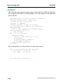
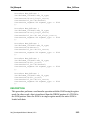
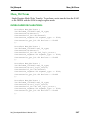
When a user calls From_String, the VHDL compiler chooses the appropriate
overloaded form of the function dependent upon the context of its use. For
example, if you write:
bool_value := From_string("FALSE");
and bool_value is declared as a boolean then the compiler invokes the first
function which is designed to accommodate boolean return types.
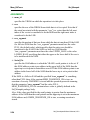
The function starts at the left most index of the string when converting the string
to the appropriate value. It then searches for the characters to be converted to the
specified type skipping over any white spaces. The function reads characters until
it reaches the end of the string, the first white space following all necessary
characters, or a NUL character.
Std_DevelopersKit User’s Manual, V2.2
1-5
From_String
Std_IOpak
RESULT:
The function returns a type dependent on context. For vector return types, the
length of the returned vector is determined by the number of characters that are
converted. The returned vector is always descending and the right most element
has an index of 0. This does not preclude the user from assigning this vector to
another vector of the same type and length but of a different range.
If an invalid character is encountered in the process of converting the string to the
specified type or if too few characters are found, or too many characters are found
an error assertion is issued and the value T’left is returned where T is the return
type. For vectors an error results in the entire vector being filled with T’left where
T is the base type of the vector.
EXAMPLES:
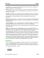
Given that the variable i is an integer then
i := From_String("bb32bb33");
sets i equal to 32 since conversion stops at the third blank space in the string. If r is
a real number then
r := From_String("-354.56");
returns the real number -354.56;
1-6
Std_DevelopersKit User’s Manual, V2.2
Std_IOpak
From_String (boolean)
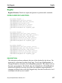
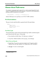
From_String (boolean)
To convert from a string to a boolean.
OVERLOADED DECLARATION:
Function From_String (
str : IN string
-- string to be converted
) return boolean;
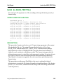
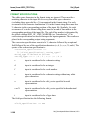
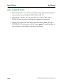
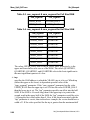
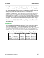
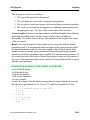
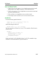
DESCRIPTION:
This overloaded function From_String converts a string to a boolean value. The
function starts at the left most index of the string and searches for the characters to
be converted to a boolean value skipping over any white spaces. The function
reads characters until it reaches the end of the string, the first white space
following all necessary characters, or a NUL character. The character sequence
following the leading white spaces must be one of the two character sequences
“FALSE” or “TRUE” for the conversion to succeed. Case is ignored.
RESULT:
This function returns a boolean value.
BUILT IN ERROR TRAPS:
If an invalid character is encountered in the process of converting the string to a
boolean or if too few characters (including a string of zero length) are found, or
too many characters are found an error assertion is issued and the value
BOOLEAN’left (FALSE) is returned.
EXAMPLES:
Given that bool is a boolean variable, then the following line sets bool to the value
TRUE:
bool := From_String("bbTruE" & NUL & "FALSE");
The following two lines set bool to FALSE and issue an error assertion:
bool := From_String ("T");
bool := From_String("bbfindTRUEinhere");
Std_DevelopersKit User’s Manual, V2.2
1-7
From_String (bit)
Std_IOpak
From_String (bit)
To convert from a string to a bit.
OVERLOADED DECLARATION:
Function From_String (
str:IN string
-- string to be converted
) return bit;
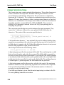
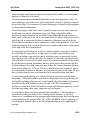
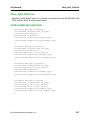
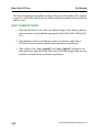
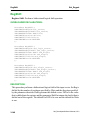
DESCRIPTION:
This overloaded function From_String converts a string to a bit value. The
function starts at the left most index of the string and searches for the characters to
be converted to a bit value skipping over any white spaces. The function reads the
first character after the white spaces and, if it is either a ‘0’ or a ‘1’, convert it to a
bit value.
RESULT:
This function returns a bit value.
BUILT IN ERROR TRAPS:
1. If the string has a length of zero, is filled with white spaces, or has no nonwhite space character to the left of a NUL character then an error assertion
is issued and the value BIT’left (‘0’) is returned.
2. If the first non-white space character that is encountered is neither a ‘0’ or a
‘1’ then an error assertion is issued and the value BIT’left (‘0’) is returned.
EXAMPLES:
Given that bit_val is a bit variable, then the following line sets bit_val to the value
‘1’:
bit_val:= From_String("b100");
The following line sets bit_val to the value ‘0’:
bit_val := From_String ("0");
The following line sets bit_val to the value ‘0’ but also causes an error assertion to
be issued.
bit_val := From_String ("bbbbb" & NUL & "1101");
1-8
Std_DevelopersKit User’s Manual, V2.2
Std_IOpak
From_String (severity_level)
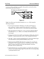
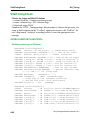
From_String (severity_level)
To convert from a string to a Severity_Level.
OVERLOADED DECLARATION:
Function From_String (
str: IN string-- string to be converted
) return Severity_Level;
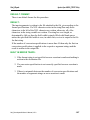
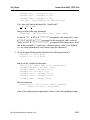
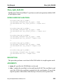
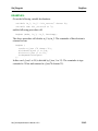
DESCRIPTION:
This overloaded function From_String converts a string to a Severity_Level. The
function starts at the left most index of the string, skipping over any white spaces.
The function reads characters until it reaches the end of the string, the first white
space following all necessary characters, or a NUL character. The character
sequence following the leading white spaces must be one of the character
sequences: “NOTE”, “WARNING”, “ERROR”, or “FAILURE” for the
conversion to succeed. Case is ignored.
RESULT:
This function returns a Severity_Level.
BUILT IN ERROR TRAPS:
If an invalid character is encountered in the process of converting the string to a
Severity_Level or if too few characters (including a string of zero length) are
found, or too many characters are found an error assertion is issued and the value
Severity_Level’left (NOTE) is returned.
Std_DevelopersKit User’s Manual, V2.2
1-9
From_String (severity_level)
Std_IOpak
EXAMPLES:
Given that severity is a variable of type Severity_Level, then the following line
sets severity to the value NOTE:
severity := From_String("NOTE" & NUL);
The following line sets severity to the value ERROR:
severity:=From_String("bbERROR" & NUL & "NOTE");
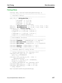
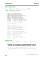
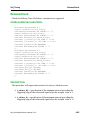
Given the following code segment:
variable str12 : string(1 to 12);
variable sev : Severity_Level;
str11 := "WARNINGERROR";
sev := From_String(sev);
The invocation of From_String causes an error assertion to be made and sev is
assigned the value NOTE. The following invocation of From_String also causes
an error assertion.
severity := From_String("bbbFAILUREtest");
1-10
Std_DevelopersKit User’s Manual, V2.2
Std_IOpak
From_String (character)
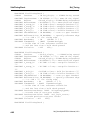
From_String (character)
To convert from a string to a character.
OVERLOADED DECLARATION:
Function From_String (
str: IN string-- string to be converted
) return character;
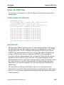
DESCRIPTION:
This overloaded function From_String returns the left most character of a string.
RESULT:
This function returns a character.
BUILT IN ERROR TRAPS:
If the string is of zero length or if the first character is a NUL character then an
error assertion is made and a NUL character is returned.
EXAMPLES:
Given that c is a character variable then the line:
c := From_String("This is a test");
sets c equal to ‘T’. The following two lines set c equal to the NUL character and
cause an error assertion to be made:
c := From_String(NUl & "This is a test");
c := From_String("");
Std_DevelopersKit User’s Manual, V2.2
1-11
From_String (integer)
Std_IOpak
From_String (integer)
To convert from a string to an Integer.
OVERLOADED DECLARATION:
Function From_String (
str: IN string-- string to be converted
) return Integer;
DESCRIPTION:
This overloaded function From_String converts a string to an integer. The
function starts at the left most index of the string and searches for the characters to
be converted to an integer skipping over any white spaces. The function reads
characters until it reaches the end of the string, the first white space following all
necessary characters, or a NUL character. The digit sequence may be preceded by
a plus or a minus sign and may have leading zeros.
RESULT:
This function returns an integer.
BUILT IN ERROR TRAPS:
If an invalid character is encountered in the process of converting the string to an
integer or if too few characters (including a string of zero length) are found, or too
many characters are found an error assertion is issued and the value
INTEGER’left is returned.
EXAMPLES:
Given that n is an integer then the following sequence sets n equal to 32:
n := From_String("32bb56");
The following line sets n equal to -347:
n := From_String("-347bbbhello");
1-12
Std_DevelopersKit User’s Manual, V2.2
Std_IOpak
From_String (real)
From_String (real)
To convert from a string to a real.
OVERLOADED DECLARATION:
Function From_String (
str: IN string-- string to be converted
) return real;
DESCRIPTION:
This overloaded function From_String converts a string to a real. The function
starts at the left most index of the string and searches for the characters to be
converted to a real skipping over any white spaces. The function reads characters
until it reaches the end of the string, the first white space following all necessary
characters, or a NUL character. The string representing the real number must have
the following format:
<real> ::= [<sign>]nnnn[.mmmm]
<sign> ::= + | -
The digit strings nnnn and mmmm may have any length provided that the real
number represented does not have a magnitude that is too large to be represented
by a real number on the machine on which the VHDL compiler and simulator is
being run. Also, leading zeros are acceptable in the string.
RESULT:
This function returns a real.
BUILT IN ERROR TRAPS:
If an invalid character is encountered in the process of converting the string to a
real or if too few characters (including a string of zero length) are found, or too
many characters are found an error assertion is issued and the value real’left is
returned.
Std_DevelopersKit User’s Manual, V2.2
1-13
From_String (real)
Std_IOpak
EXAMPLE:
Given that r is a real number then the following line causes r to be set equal to 354.78:
r := From_String("b-354.78");
The following line causes r to be set equal to -35.687:
r := From_String("-00035.687000");
1-14
Std_DevelopersKit User’s Manual, V2.2
Std_IOpak
From_String (time)
From_String (time)
To convert from a string to a time.
OVERLOADED DECLARATION:
Function From_String (
str: IN string-- string to be converted
) return time;
DESCRIPTION:
This overloaded function From_String converts a string to a time value. The
function starts at the left most index of the string and searches for the characters to
be converted to a time value skipping over any white spaces. The function reads
characters until it reaches the end of the string, the first white space following all
necessary characters, or a NUL character. The string representing the time value
must have the following format:
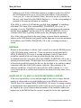
<time> ::= [<sign>]nnnn[.mmmm]b<t_unit>
<sign> ::= + | <t_unit> ::= fs | ps | ns | us | ms | sec | min | hr
The digit strings nnnn and mmmm may have any length provided that the time
value represented does not have a magnitude that is too large to be represented by
a real number on the machine on which the VHDL compiler and simulator is
being run. There should be a blank space between the real number and its
associated unit. The unit must be included for the conversion to succeed.
RESULT:
This function returns a time value.
BUILT IN ERROR TRAPS:
1. If an invalid character is encountered in the process of converting the string
to a time value or if too few characters (including a string of zero length)
are found, or too many characters are found an error assertion is issued and
the value time’left is returned.
2. If an invalid character sequence is specified for t_unit then an error
assertion is made and the value time’left is returned.
Std_DevelopersKit User’s Manual, V2.2
1-15
From_String (time)
Std_IOpak
EXAMPLE:
Given that t is a time variable then the following line sets t equal to 893.56 ms:
t := From_String("bbb893.56bmsbbgarbage");
The following line causes an error assertion to be made:
t := From_String("857.3bpshello");
1-16
Std_DevelopersKit User’s Manual, V2.2
Std_IOpak
From_String (std_ulogic)
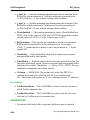
From_String (std_ulogic)
To convert from a string to a std_ulogic value.
OVERLOADED DECLARATION:
Function From_String (
str: IN string-- string to be converted
) return std_ulogic;
DESCRIPTION:
This overloaded function From_String converts a string to a std_ulogic value. The
function starts at the left most index of the string and searches for the characters to
be converted to a std_ulogic value skipping over any white spaces. The function
reads the first character after the white spaces and, if it is one of the valid
characters (‘U’, ‘X’, ‘0’, ‘1’, ‘Z’, ‘W’, ‘L’, ‘H’, ‘-’), convert it to a std_ulogic
value. Case is ignored.
RESULT:
This function returns a std_ulogic value.
BUILT IN ERROR TRAPS:
1. If the string has a length of zero, is filled with white spaces, or has no nonwhite space character to the left of a NUL character then an error assertion
is issued and the value std_ulogic’left (‘U’) is returned.
2. If the first non-white space character that is encountered is not one of the
valid characters then an error assertion is issued and the value
std_ulogic’left (‘U’) is returned.
Std_DevelopersKit User’s Manual, V2.2
1-17
From_String (std_ulogic)
Std_IOpak
EXAMPLES:
Given that ulogic_val is a std_ulogic variable, then the following line sets
ulogic_val to the value ‘1’:
ulogic_val:= From_String("b100");
The following line sets ulogic_val to the value ‘Z’:
ulogic_val := From_String ("bbbZ01b");
The following line sets ulogic_val to the value ‘U’ but also causes an error
assertion to be issued.
ulogic_val:=From_String ("bbbbb"& NUL & "1101");
1-18
Std_DevelopersKit User’s Manual, V2.2
Std_IOpak
From_String (std_ulogic_vector)
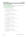
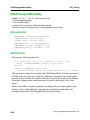
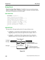
From_String (std_ulogic_vector)
To convert a string to a std_ulogic_vector.
OVERLOADED DECLARATION:
Function From_String (
str: IN string-- string to be converted
) return std_ulogic_vector;
DESCRIPTION:
This overloaded function From_String converts a string to a std_ulogic_vector
value. The function starts at the left most index of the string and searches for the
characters to be converted to a std_ulogic_vector skipping over any white spaces.
The function then reads characters until it reaches the end of the string, the first
white space following a sequence of non-white space characters, or a NUL
character. The valid character set is ‘U’, ‘X’, ‘0’, ‘1’, ‘Z’, ‘W’, ‘L’, ‘H’, and ‘-’
and the case of the characters is ignored.
RESULT:
This function returns a std_ulogic_vector whose length is equal to the number of
non-white space characters read by the function. The returned vector has a
descending range with the right most index being 0. This does not preclude the
user from assigning this vector to another vector of the same type and length but
of a different range.
BUILT IN ERROR TRAPS:
1. If the string has a length of zero, is filled with white spaces, or has no nonwhite space characters to the left of a NUL character then an error assertion
is issued and a vector of zero length is returned.
2. If one of the non-white space characters read by the function is an invalid
character than an error assertion is made and a vector filled with
std_ulogic’left (‘U’) with a length equal to the number of non-white space
characters read by the function is returned.
Std_DevelopersKit User’s Manual, V2.2
1-19
From_String (std_ulogic_vector)
Std_IOpak
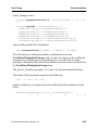
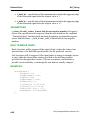
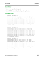
EXAMPLES:
Given the following variable declaration:
variable u_vct: std_ulogic_vector (15 downto 8);
the following line sets u_vct equal to "0-ZU1010":
u_vct := From_String("bbb0-ZU1010bbb1010");
The following line causes an error assertion to be issued and cause u_vct to be set
equal to the vector "UUUUUUUU".
u_vct := From_String("bbb0U11X1PPb");
1-20
Std_DevelopersKit User’s Manual, V2.2
Std_IOpak
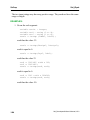
From_String (std_logic_vector)
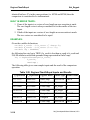
From_String (std_logic_vector)
To convert a string to a std_logic_vector.
OVERLOADED DECLARATION:
Function From_String (
str: IN string-- string to be converted
) return std_logic_vector;
DESCRIPTION:
This overloaded function From_String converts a string to a std_logic_vector
value. The function starts at the left most index of the string and searches for the
characters to be converted to a std_logic_vector skipping over any white spaces.
The function then reads characters until it reaches the end of the string, the first
white space following a sequence of non-white space characters, or a NUL
character. The valid character set is ‘U’, ‘X’, ‘0’, ‘1’, ‘Z’, ‘W’, ‘L’, ‘H’, and ‘-’
and the case of the characters is ignored.
RESULT:
This function returns a std_logic_vector whose length is equal to the number of
non-white space characters read by the function. The returned vector has a
descending range with the right most index being 0. This does not preclude the
user from assigning this vector to another vector of the same type and length but
of a different range.
BUILT IN ERROR TRAPS:
1. If the string has a length of zero, is filled with white spaces, or has no nonwhite space characters to the left of a NUL character then an error assertion
is issued and a vector of zero length is returned.
2. If one of the non-white space characters read by the function is an invalid
character than an error assertion is made and a vector filled with
std_logic’left (‘U’) with a length equal to the number of non-white space
characters read by the function is returned.
Std_DevelopersKit User’s Manual, V2.2
1-21
From_String (std_logic_vector)
Std_IOpak
EXAMPLES:
Given the following variable declaration:
variable vect : std_logic_vector (15 downto 8);
the following line sets vect equal to "0-ZU1010":
vect := From_String("bbb0-ZU1010bbb1010");
The following line causes an error assertion to be issued and cause vect to be set
equal to the vector "UUUUUUUU".
vect := From_String("bbb0U11X1PPb");
1-22
Std_DevelopersKit User’s Manual, V2.2
Std_IOpak
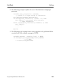
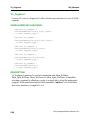
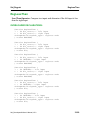
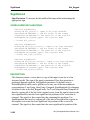
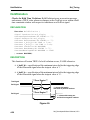
From_BinString
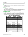
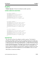
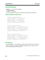
From_BinString
To convert a binary string to a bit vector
DECLARATION:
Function From_BinString (
str: IN string-- string to be converted
) return bit_vector;
DESCRIPTION:
This function From_BinString converts a string to a bit_vector value. The
function starts at the left most index of the string and searches for the characters to
be converted to a bit_vector skipping over any white spaces. The function then
reads characters until it reaches the end of the string, the first white space
following a sequence of non-white space characters, or a NUL character. The
valid characters are ‘0’ and ‘1’.
RESULT:
This function returns a bit_vector whose length is equal to the number of nonwhite space characters read by the function. The returned vector has a descending
range with the right most index being 0. This does not preclude the user from
assigning this vector to another vector of the same type and length but of a
different range.
BUILT IN ERROR TRAPS:
1. If the string has a length of zero, is filled with white spaces, or has no nonwhite space characters to the left of a NUL character then an error assertion
is issued and a vector of zero length is returned.
2. If one of the non-white space characters read by the function is an invalid
character than an error assertion is made and a vector filled with bit’left
(‘0’) with a length equal to the number of non-white space characters read
by the function is returned.
Std_DevelopersKit User’s Manual, V2.2
1-23
From_BinString
Std_IOpak
EXAMPLES:
Given the following variable declaration:
variable vect : bit_vector (15 downto 8);
the following line sets vect equal to "01101111":
vect := From_BinString("bbb01101111bbb1010");
The following line causes an error assertion to be issued and cause vect to be set
equal to the vector "00000000".
vect := From_BinString("bbb000000PPb");
1-24
Std_DevelopersKit User’s Manual, V2.2
Std_IOpak
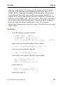
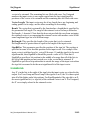
From_OctString
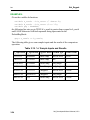
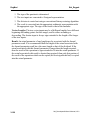
From_OctString
To convert an octal string to a bit vector
DECLARATION:
Function From_OctString (
str: IN string-- string to be converted
) return bit_vector;
DESCRIPTION:
This function From_OctString converts a string to a bit_vector value. The
function starts at the left most index of the string and searches for the characters to
be converted to a bit_vector skipping over any white spaces. The function then
reads characters until it reaches the end of the string, the first white space
following a sequence of non-white space characters, or a NUL character. The
valid characters are ‘0’, ‘1’, ‘2’, ‘3’, ‘4’, ‘5’, ‘6’, and ‘7’. Each valid character is
converted into its equivalent three digit long binary sequence.
RESULT:
This function returns a bit_vector whose length is equal to three times the number
of non-white space characters read by the function. The returned vector has a
descending range with the right most index being 0. This does not preclude the
user from assigning this vector to another vector of the same type and length but
of a different range.
BUILT IN ERROR TRAPS:
1. If the string has a length of zero, is filled with white spaces, or has no nonwhite space characters to the left of a NUL character then an error assertion
is issued and a vector of zero length is returned.
2. If one of the non-white space characters read by the function is an invalid
character than an error assertion is made and a vector filled with bit’left
(‘0’) with a length equal to three times the number of non-white space
characters read by the function is returned.
Std_DevelopersKit User’s Manual, V2.2
1-25
From_OctString
Std_IOpak
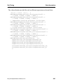
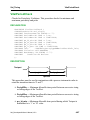
EXAMPLES:
Given the following variable declaration:
variable vect : bit_vector (15 downto 4);
the following line sets vect equal to "001111011101":
vect := From_OctString("bbb1735bbb1010");
The following line causes an error assertion to be issued and cause vect to be set
equal to the vector "000000000000".
vect := From_OctString("bbb72PPb");
1-26
Std_DevelopersKit User’s Manual, V2.2
Std_IOpak
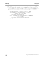
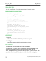
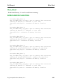
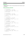
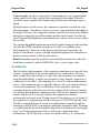
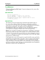
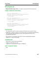
From_HexString
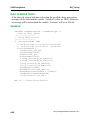
From_HexString
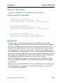
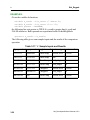
Convert a Hexadecimal String to a Bit_Vector
PURPOSE:
To convert a Hexadecimal string to a bit vector
DECLARATION:
Function From_HexString (
str: IN string-- string to be converted
) return bit_vector;
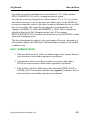
DESCRIPTION:
This function From_HexString converts a string to a bit_vector value. The
function starts at the left most index of the string and searches for the characters to
be converted to a bit_vector skipping over any white spaces. The function then
reads characters until it reaches the end of the string, the first white space
following a sequence of non-white space characters, or a NUL character. The
valid characters are ‘0’, ‘1’, ‘2’, ‘3’, ‘4’, ‘5’, ‘6’, ‘7’, ‘8’, ‘9’, ‘A’, ‘B’, ‘C’, ‘D’,
‘E’, and ‘F’ and the case of the characters is ignored. Each valid character is
converted into its equivalent four digit long binary sequence.
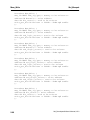
RESULT:
This function returns a bit_vector whose length is equal to four times the number
of non-white space characters read by the function. The returned vector has a
descending range with the right most index being 0. This does not preclude the
user from assigning this vector to another vector of the same type and length but
of a different range.
Std_DevelopersKit User’s Manual, V2.2
1-27
From_HexString
Std_IOpak
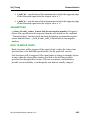
BUILT IN ERROR TRAPS:
1. If the string has a length of zero, is filled with white spaces, or has no nonwhite space characters to the left of a NUL character then an error assertion
is issued and a vector of zero length is returned.
2. If one of the non-white space characters read by the function is an invalid
character than an error assertion is made and a vector filled with bit’left
(‘0’) with a length equal to four times the number of non-white space
characters read by the function is returned.
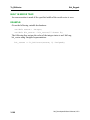
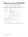
EXAMPLES:
Given the following variable declaration:
variable vect : bit_vector (15 downto 4);
the following line sets vect equal to "001111011101":
vect := From_HexString("bbb3DDbbb1010");
The following line causes an error assertion to be issued and cause vect to be set
equal to the vector "000000000000".
vect := From_HexString("bbb72Pb");
1-28
Std_DevelopersKit User’s Manual, V2.2
Std_IOpak
To_String
To_String
To_String is a function which converts expressions of any pre-declared type that
was declared in the package STANDARD or of any type declared in the package
STD_LOGIC_1164 to a string representation of its value.
GENERAL DESCRIPTION:
An optional format string provides the flexibility to control the appearance of the
resulting string. Left and right justified formats, as well as a default format are
accommodated.
There are ten overloaded forms of the function which include conversion from:
1.
2.
3.
4.
5.
6.
7.
8.
9.
10.
11.
Boolean
Bit
Severity_Level
Character
Integer
Real
Time
Bit_Vector
Std_ulogic
Std_logic_vector
Std_ulogic_vector
When a user calls To_String which overloaded form of the function the VHDL
compiler chooses depends upon the context of its use. For example, if you write...
assert false
report "2 * pi :=" & To_String (2.0*3.14159);
the compiler invokes the sixth function which is designed to accommodate real
numbers. Notice that in the example provided, no format specification had been
made. This is called default formatting and the function represents the real number
in a standard notation.
Std_DevelopersKit User’s Manual, V2.2
1-29
To_String
Std_IOpak
FORMAT SPECIFICATIONS:
The format string provides conversion specifications which are used to interpret
the input value. The conversion specifications consist of a % character followed
by some optional fields followed by one of the specification characters (d, f, s, and
t). When the input value is of type time then the format string includes time_unit
after the conversion character t. In this way the input time is scaled to this
time_unit before conversion to the string representation takes place. The syntax of
the format specification is:
<format_specification> ::=
"% [<left_justification>]
[<field_specification>]<string_type>"
| "%[<left_justification>] [<field_specification>] t
[<t_unit>]"
<left_justification> ::= '-'
A left_justification character ‘-’ may optionally be used in the field width format
specification to indicate that the expression being converted to string format be
left justified. If right justification is desired, then the ‘-’ is simply eliminated.
The field specification has the following format:
<field_specification> ::= nnn.mmm
A digit string nnn specifies the maximum field width. The result string has a width
that is at least this wide, and wider if necessary. If the converted string has fewer
characters than the field width it is padded on the left (or the right, if left
justification has been specified) to make up the field width. The padding character
is a blank space. A period separates the field width from the precision.
A digit string mmm specifies the precision, which is the count of the maximum
number of characters of the input value to be converted to a string or the number
of digits that is placed to the right of the decimal point if the input value is a real
number or a time. For an input of type integer the precision specifies the minimum
number of digits used to represent the integer in the output string. If the number of
digits that are necessary to represent the integer is less than the precision then the
string representation is padded on the left with zeros. (i.e. The number 2 with a
format string of “%4.2d” is converted to the string "bb02".) If the precision is not
specified then the string is never padded with zeros.
1-30
Std_DevelopersKit User’s Manual, V2.2
Std_IOpak
To_String
String_type has the following format:
<string_type> ::= d | f | s | t | o | x | X
where the meaning of each letter is defined as follows:
d
input value is considered to be an integer
f
input value is considered to be a real number
s
input is considered to be of one of the enumeration types
(boolean, severity_level, character, bit, bit_vector, std_ulogic,
std_logic_vector)
t
input is considered to be of type time
o
input value is considered to be a bit_vector. In this case the
resulting string represents the vector with the use of octal digits
x or X
input value is considered to be a bit_vector. In this case the
resulting string represents the vector with the use of hexadecimal
digits
Note that a letter may only be used with the corresponding type described above.
For instance, s may not be used in a format string that applies to an integer.
When the input value is of type time then t_ unit specifies the unit in which the
result is represented. If the format string is specified, then a time unit must be
specified.
<t_unit> ::= fs | ps | ns | us | ms | sec
fs
output is a string representation of time in femto seconds
ps
output is a string representation of time in pico seconds
ns
output is a string representation of time in nano seconds
us
output is a string representation of time in micro seconds
ms
output is a string representation of time in milli seconds
sec
output is a string representation of time in seconds
Std_DevelopersKit User’s Manual, V2.2
1-31
To_String
Std_IOpak
DEFAULT FORMAT:
If the user does not specify the format string the following default values are used:
Table 1-1. Default Format String Values
Input Type
Default Format String
integer
"%d"
real
"%f"
enumeration types
"%s"
time
"%t dynamic_unit"
The default format auto sizes the length of the minimum field width to match the
minimum number of characters needed to represent the input value as a string. For
an input value of type time, the input value is scaled to a suitable time unit. The
time unit is only selected dynamically if no format string is specified.
RESULT:
The string that is returned by the function has an ascending range whose left index
starts a 1 and has a length that is at least as long as that specified by the field
width. If specified field width is smaller than the minimum number of characters
needed to represent the input value then the length of the result is expanded to this
minimum number of characters. As a result, the user must be careful not to assign
an invocation of this function to a variable if auto sizing occurs for the given input
and format string. For instance, assigning an invocation of this function that uses
the default format for integers to a string of length 3 likely causes a run time error.
The deferred constant MAX_STRING_LEN represents the maximum length of
the result string. Its value is globally set to 256 in the package Std_IOpak. If a
string of a larger length is required, then the constant MAX_STRING_LEN must
be set to the desired integer value. If the format string specifies a field width larger
than MAX_STRING_LEN (256) then the length of the result string is set to
MAX_STRING_LEN (256).
1-32
Std_DevelopersKit User’s Manual, V2.2
Std_IOpak
To_String
EXAMPLES:
1. a)Given the following line:
str := To_String(265.3, "%8.2f");
Since the field width is 8 and the precision is 2, the result string is of at least
length 8 and contains two digits after the decimal point. The result string is
also right justified. Below is the string that is returned.
"bb265.30"
2. b)When the function invocation is changed as follows:
str := To_String(265.3, "%-8.2f");
The field width is still at least 8 with a precision of 2, but the result is left
justified. The string that is returned is shown below.
"265.30bb"
3. c)When To_String is invoked as follows:
str := To_String(123456, "%16d");
First the integer 123456 is converted to the string: "123456". The format
string "%16d" means field width is 16 and the precision is ignored, all of
the characters are printed. As a result, the following string is returned:
"bbbbbbbbbb123456"
4. d)A format string of "%16.8" causes the output string to use padding with
zeros to achieve a number with 8 digits. The resulting string is shown
below:
"bbbbbbbb00123456"
If the format string was "8.4" the result would be as follows:
"bb123456"
The resulting string has a length of 8 as specified by the field width. The
specified precision is 4. Since the minimum number of digits needed to
represent the integer is greater than the precision (the minimum length of
the integer), the precision requirement is satisfied and all 6 of the integer’s
digits are placed in the string.
Std_DevelopersKit User’s Manual, V2.2
1-33
To_String (boolean)
Std_IOpak
To_String (boolean)
To convert a boolean value to a string according to the specification provided by
the format string
OVERLOADED DECLARATION:
Function To_String (
val: IN boolean; -- input value to be converted to a string
format:IN string -- conversion specification
) return string;
DESCRIPTION:
This function converts the boolean input val to a string representation. An optional
format string provides the flexibility to control the appearance of the resulting
string. Left and right justification formats, as well as a default format are
accommodated.
FORMAT SPECIFICATIONS:
The format string provides conversion specifications which are used to interpret
the input value. The conversion specifications consist of a % character followed
by some optional fields followed by the specification character s. The syntax of
the format specification is:
<format_specification> ::=
"% [<left_justification>] [<field_specification>] s"
<left_justification> ::= '-'
A left_justification character ‘-’ may optionally be used in the field width format
specification to indicate that the expression being converted to string format be
left justified. If right justification is desired, then the ‘-’ is simply eliminated.
The field specification has the following format:
<field_specification> ::= nnn.mmm
A digit string nnn specifies the maximum field width. The result string has a width
that is at least this wide, and wider if necessary. If the converted string has fewer
characters than the field width it is padded on the left (or the right, if left
justification has been specified) to make up the field width. The padding character
is a blank space. A period separates the field width from the precision.
1-34
Std_DevelopersKit User’s Manual, V2.2
Std_IOpak
To_String (boolean)
A digit string mmm specifying the precision, which is the count of the maximum
number of characters of the input value to be converted to a string
DEFAULT FORMAT:
If the user does not specify the format string then a default format string “%s” is
used for an input value of type boolean. The default format auto sizes the length of
the minimum field width to match the minimum number of characters needed to
represent the input boolean value as a string.
RESULT:
The string that is returned by the function has an ascending range whose left index
starts a 1 and has a length that is at least as long as that specified by the field
width. If specified field width is smaller than the minimum number of characters
needed to represent the input value then the length of the result is expanded to this
minimum number of characters. As a result, the user must be careful not to assign
an invocation of this function to a variable if auto sizing occurs for the given input
and format string. For instance, assigning an invocation of this function that uses
the default format for boolean variable to a string of length 3 causes a run time
error.
If the format string specifies a field width larger than MAX_STRING_LEN (256)
then the length of the result string is set to MAX_STRING_LEN (256).
BUILT IN ERROR TRAPS:
1. If the format string is not correctly specified an error assertion is made.
2. If the format string type does not match the input value (i.e. if the format
string is “%5d” and the input value is boolean) an error assertion is made.
Std_DevelopersKit User’s Manual, V2.2
1-35
To_String (boolean)
Std_IOpak
EXAMPLES:
Given the variable declarations:
Constant
variable
variable
variable
variable
max_address : integer := 1024;
str16 : STRING(1 TO 16);
flag : boolean := false;
index : Integer;
bool : Boolean;
1. Then the following statement converts the boolean variable flag to a string
of length 16 and assign it to the variable str16.
str16 := To_String(flag, "%16s");
Now the string str16 has the value "bbbbbbbbbbbFALSE". Note the default
of right justification was used.
2. Given the following piece of VHDL code
index := 1;
assert false
report "Is index less than max_address? "
& To_String(index < max_address)
severity NOTE;
Note that first the expression index < max_address is evaluated and it
returns the boolean value TRUE. This boolean, TRUE, then inputs to the
function To_String. Since no format string is specified the default format is
used. The result string holds the value "TRUE" which has a length of four.
3. If we want only a few characters of the input value to be converted to a
string (e.g. we want only "F" or "T" for a boolean), then the function
invocation would have the format:
To_String(bool, "%.1s")
This returns "T" if the variable bool is TRUE and "F" if the variable bool
is false. Notice that To_String returns strings consisting of upper case
letters.
To_String(bool, "%-5.1s")
returns "Tbbbb" if bool is true, which is left justified, and "Fbbbb" if bool
is false.
1-36
Std_DevelopersKit User’s Manual, V2.2
Std_IOpak
To_String (bit)
To_String (bit)
To convert a bit value to a string according to the specification provided by the
format string.
OVERLOADED DECLARATION:
Function To_String (
val:IN bit;-- input value to be converted to a string
format:IN string-- conversion specification
) return string;
DESCRIPTION:
This function converts the input bit val to a string representation. An optional
format string provides the flexibility to control the appearance of the resulting
string. Left and right justification formats, as well as a default format are
accommodated.
FORMAT SPECIFICATIONS:
The format string provides conversion specifications which are used to interpret
the input value. The conversion specifications consist of a % character followed
by some optional fields followed by the specification character s.
The syntax for this format specification is:
<format_specification> ::=
"% [<left_justification>] [<field_specification>] s"
<left_justification> ::= '-'
A left_justification character ‘-’ may optionally be used in the field width format
specification to indicate that the expression being converted to string format be
left justified. If right justification is desired, then the ‘-’ is simply eliminated.
The field width specification has the following format:
<field_specification> ::= nnn.mmm for bit values
A digit string nnn specifies the maximum field width. The result string has a width
that is at least this wide, and wider if necessary. If the converted string has fewer
characters than the field width it is padded on the left (or the right, if left
Std_DevelopersKit User’s Manual, V2.2
1-37
To_String (bit)
Std_IOpak
justification has been specified) to make up the field width. The padding character
is a blank space. A period separates the field width from the precision.
A digit string mmm specifies the precision, which is the count of the maximum
number of characters of the input value to be converted to a string. In this case,
regardless of the precision, only one character can be converted to a string.
DEFAULT FORMAT:
If the user does not specify the format string then a default format string “%s” is
used for the input value of type bit. The default format auto sizes the length of the
minimum field width to 1 (one).
RESULT:
The string that is returned by the function has an ascending range whose left index
starts a 1 and has a length that is at least as long as that specified by the field
width. If the specified field width is less than 1 then it is set to the default
minimum field width of 1 for this case. The length of result string is 1. If the
format string specifies a field width larger than MAX_STRING_LEN (256) then
the length of the result is set to MAX_STRING_LEN.
BUILT IN ERROR TRAPS:
1. If the format string is not correctly specified an error assertion is made.
2. If the format string type does not match the input value (i.e. if the format
string is “%5d” and the input value is of type bit) an error assertion is made.
1-38
Std_DevelopersKit User’s Manual, V2.2
Std_IOpak
To_String (bit)
EXAMPLES:
Given the variable declarations:
variable status_reg : STRING(1 TO 8);
variable carry_out : bit;
1. Then the following statement converts carry_out from a bit to a string of
length 1 and assign it to the slice of the status_reg.
status_reg(1) := To_String(carry_out);
The previous statement uses the default format.
2. The following code segment:
Variable cout : bit;
cout := '1';
status_reg := To_string(cout, "%-8s");
causes the string "1bbbbbbb" to be assigned to status_reg.
Std_DevelopersKit User’s Manual, V2.2
1-39
To_String (character)
Std_IOpak
To_String (character)
To convert a character value to a string according to the specification provided by
a format string. This function is primarily a debugging tool.
OVERLOADED DECLARATION:
Function To_String (
val: IN character;-- input value to be converted to a string
format:IN string-- conversion specification
) return string;
DESCRIPTION:
This function converts the input character, val, to a string representation. An
optional format string provides the flexibility to control the appearance of the
resulting string. Left and right justification formats, as well as a default format are
accommodated.
This function is primarily a debugging tool that should be used to view nonprinting characters.
FORMAT SPECIFICATIONS:
The format string provides conversion specifications which are used to interpret
the input value. The conversion specifications consist of a % character followed
by some optional fields followed by the specification character s.
<format_specification> ::=
"% [<left_justification>] [<field_specification>] s"
<left_justification> ::='-'
A left_justification character ‘-’ may optionally be used in the field width format
specification to indicate that the expression being converted to string format be
left justified. If right justification is desired, then the ‘-’ is simply eliminated.
The field specification has the following format:
<field_specification> ::= nnn.mmm
A digit string nnn specifies the maximum field width. The result string has a width
that is at least this wide, and wider if necessary. If the converted string has fewer
characters than the field width it is padded on the left (or the right, if left
1-40
Std_DevelopersKit User’s Manual, V2.2
Std_IOpak
To_String (character)
justification has been specified) to make up the field width. The padding character
is a blank space. A period separates the field width from the precision.
A digit string mmm normally specifies the precision, which is the count of the
maximum number of characters of the input value to be converted to a string. In
this case, the precision is ignored since only one input character is passed to the
procedure.
DEFAULT FORMAT:
If the user does not specify the format string then a default format string “%s” is
used for the input value of type character. The default format auto sizes the length
of the minimum field width to 1 (one) if the input val is one of the 95 ASCII
printable characters (graphic characters) and the field width is set to 3 (three) if
the input val is one of the non-printable (non-graphic) ASCII characters.
RESULT:
The string that is returned by the function has an ascending range whose left index
starts a 1 and has a length that is at least as long as that specified by the field
width. If the specified field width is less than the default length needed it is set to
1 if input val is a graphic character and set to 3 if input val is a non-graphic
character. As a result, the user must be careful not to assign an invocation of this
function to a variable if auto sizing occurs for the given input and format string.
For instance, assigning an invocation of this function that uses the default format
for characters to a string of length1 causes a run time error if the character is nonprintable.
If the format string specifies a field width larger than MAX_STRING_LEN (256)
then it is set to MAX_STRING_LEN and the length of the result string is 256.
BUILT IN ERROR TRAPS:
1. If the format string is not correctly specified an error assertion is made.
2. If the format string type does not match the input value (i.e. if the format
string is “%5d” and input value is of type character) an error assertion is
made.
Std_DevelopersKit User’s Manual, V2.2
1-41
To_String (character)
Std_IOpak
EXAMPLES:
Given the variable declarations:
variable ch : character;
variable str8 : String(1 TO 8);
file in_file : ASCII_TEXT IS IN "alu_test.dat";
1. In the following statement:
str8 := To_String('T', "%8s");
str8 has value "bbbbbbbT".
2. If we have the following code:
ch := fgetc(in_file);-- read a character from
-- the file attached
-- with in_file
ASSERT (StrCmp ( To_String(ch), "T") = 0)
REPORT " file alu_test.dat corrupted. "
SEVERITY ERROR;
This code reads a character from the input file alu_test.dat and convert this
character to a string of length one by the invocation of To_String(ch). Then
another function StrCmp compares this with the "T" and, if there is a
match, return zero (0). In this way the expression (StrCmp( To_String(ch),
"T") = 0) is evaluated to a boolean value of TRUE. Therefore, the error
assertion is not made. If any other character was read, the error assertion is
made.
1-42
Std_DevelopersKit User’s Manual, V2.2
Std_IOpak
To_String (character)
3. The following is a table of input characters, their ordinal values, and the
resulting output strings for the function invocation To_String(c) where c is
a character:
Table 1-2. To_String(c) Resultant Output
Input Character
Ordinal Value
Output String
NUL
0
"NUL"
ACK
6
"ACK"
A
65
"A"
b
98
"b"
DEL
127
"DEL"
3
51
"3"
?
63
"?"
Std_DevelopersKit User’s Manual, V2.2
1-43
To_String (severity_level)
Std_IOpak
To_String (severity_level)
To convert a severity_level to a string according to the specification provided by a
format string.
OVERLOADED DECLARATION:
Function To_String (
val: IN severity_level;-- value to be converted to a string
format:IN string-- conversion specification
) return string;
DESCRIPTION:
This function converts the input severity_level, val, to a string representation. An
optional format string provides the flexibility to control the appearance of the
resulting string. Left and right justification formats, as well as a default format are
accommodated.
FORMAT SPECIFICATIONS:
The format string provides conversion specifications which are used to interpret
the input value. The conversion specifications consist of a % character followed
by some optional fields followed by the specification character s.
<format_specification> ::=
"% [<left_justification>] [<field_specification>] s"
<left_justification> ::= '-'
A left_justification character ‘-’ may optionally be used in the field width format
specification to indicate that the expression being converted to string format be
left justified. If right justification is desired, then the ‘-’ is simply eliminated.
The field specification has the following format:
<field_specification> ::= nnn.mmm
A digit string nnn specifies the maximum field width. The result string has a width
that is at least this wide, and wider if necessary. If the converted string has fewer
characters than the field width it is padded on the left (or the right, if left
justification has been specified) to make up the field width. The padding character
is a blank space. A period separates the field width from the precision.
1-44
Std_DevelopersKit User’s Manual, V2.2
Std_IOpak
To_String (severity_level)
A digit string mmm specifies the precision, which is the count of the maximum
number of characters of the input value to be converted to a string.
DEFAULT FORMAT:
If the user does not specify the format string then a default format string “%s” is
used for the input value of type severity_level. The default format auto sizes the
length of the minimum field width to match the minimum number of characters
needed to represent the input severity_level value as a string.
RESULT:
The string that is returned by the function has an ascending range whose left index
starts a 1 and has a length that is at least as long as that specified by the field
width. If the specified field width is smaller than the minimum number of
characters needed to represent the input value then the length of the result string is
expanded to this minimum number of characters. As a result, the user must be
careful not to assign an invocation of this function to a variable if auto sizing
occurs for the given input and format string. For instance, assigning an invocation
of this function that uses the default format for severity_level to a string of length
4 causes a run time error if the severity level is WARNING.
If the format string specifies a field width larger than MAX_STRING_LEN (256)
then the length of the result is set to MAX_STRING_LEN.
BUILT IN ERROR TRAPS:
1. If the format string is not correctly specified an error assertion is made.
2. If the format string type does not match the input value (i.e. if the format
string is “%5d” and the input value is of type severity_level) an error
assertion is made.
Std_DevelopersKit User’s Manual, V2.2
1-45
To_String (severity_level)
Std_IOpak
EXAMPLE:
Given the variable declarations.
variable str8 : STRING(1 TO 8);
variable ast_level : SEVERITY_LEVEL;
The following piece of VHDL code converts the variable ast_level to a string and
print the string to the output file.
ast_level := warning;
str8 := To_String(ast_level, "%8s");
fprint(" severity level is = %s\n", str8);
Here the fprint statement prints str8 to the default output file “STD_OUTPUT”.
Note that str8 is padded on the left side with one blank space. The line that is
printed to the file is shown below:
severity level is =
1-46
WARNING
Std_DevelopersKit User’s Manual, V2.2
Std_IOpak
To_String (integer)
To_String (integer)
To convert an integer value to a string according to the specification provided by a
format string.
OVERLOADED DECLARATION:
Function To_String (
val:IN integer;-- input value to be converted to a string
format:IN string-- conversion specification
) return string;
DESCRIPTION:
This function converts the input integer, val, to a string representation. An
optional format string provides the flexibility to control the appearance of the
resulting string. Left and right justification formats, as well as a default format are
accommodated.
FORMAT SPECIFICATIONS:
The format string provides conversion specifications which are used to interpret
the input value. The conversion specifications consist of a % character followed
by some optional fields followed by the specification character d.
<format_specification> ::=
"% [<left_justification>] [<field_specification>] d"
<left_justification> ::= '-'
A left_justification character ‘-’ may optionally be used in the field width format
specification to indicate that the expression being converted to string format be
left justified. If right justification is desired, then the ‘-’ is simply eliminated.
The field specification has the following format:
<field_specification> ::= nnn .mmm
A digit string nnn specifies the maximum field width. The result string has a width
that is at least this wide, and wider if necessary. If the converted string has fewer
characters than the field width it is padded on the left (or the right, if left
justification has been specified) to make up the field width. The padding character
is a blank space. A period separates the filed width from the precision.
Std_DevelopersKit User’s Manual, V2.2
1-47
To_String (integer)
Std_IOpak
A digit string mmm specifies the precision, which is the minimum number of
digits, in the string, that is used to represent the integer. If the number of digits
that are necessary to represent the integer is less than the precision then the string
representation is padded on the left with zeros. (i.e. The number 2 with a format
string of “%4.2d” is converted to the string "bb02".) If the precision is not
specified then the string is never padded with zeros.
DEFAULT FORMAT:
If the user does not specify the format string then a default format string “%d” is
used for the input value of type integer. The default format auto sizes the length of
the minimum field width to match the minimum number of characters needed to
represent the input integer value as a string.
RESULT:
The string that is returned by the function has an ascending range whose left index
starts a 1 and has a length that is at least as long as that specified by the field
width. If the specified field width is smaller than the minimum number of
characters needed to represent the input value then the length of the result string is
expanded to this minimum number of characters. As a result, the user must be
careful not to assign an invocation of this function to a variable if auto sizing
occurs for the given input and format string. For instance, assigning an invocation
of this function that uses the default format for integers to a string of length 3
causes a run time error if the integer is 1024.
If the format string specifies a field width larger than MAX_STRING_LEN (256)
then the length of the result is set to MAX_STRING_LEN.
BUILT IN ERROR TRAPS:
1. If the format string is not correctly specified an error assertion is made.
2. If the format string type does not match the input value (i.e. if the format
string is “%s” and the input value is of type integer) an error assertion is
made.
1-48
Std_DevelopersKit User’s Manual, V2.2
Std_IOpak
To_String (integer)
EXAMPLES:
Given the variable declarations:
variable str16 : STRING(1 TO 16);
variable val : INTEGER := 1234;
Then the following statement converts the integer val to a string of length 16 and
assign it to the variable str16. The default justification, which is right justification,
is used.
str16 := To_String(val, "%16d");
The variable str16 holds the following string:
"bbbbbbbbbbbb1234"
The statement:
str16 := To_String(val, "%-16d")
has the effect of setting str16 equal to the following string:
"1234bbbbbbbbbbbb"
which is left justified.
The line:
str16(1 To 4) := To_String(val);
assigns "1234" to the specified slice of str16.
The line:
str16(1 to 8) := To_String(val,"%8.6d" );
assigns "bb001234" the specified slice of str16.
The line
str16(1 to 8) := To_String(val, "%8.2d");
assigns "bbbb1234" to the specified slice of str16.
Std_DevelopersKit User’s Manual, V2.2
1-49
To_String (real)
Std_IOpak
To_String (real)
To convert a real value to a string according to the specification provided by a
format string.
OVERLOADED DECLARATION:
Function To_String (
val: IN real;-- input value to be converted to a string
format:IN string-- conversion specification
) return string;
DESCRIPTION:
This function converts the input real val to a string representation. An optional
format string provides the flexibility to control the appearance of the resulting
string. Left and right justification formats, as well as a default format are
accommodated.
FORMAT SPECIFICATIONS:
The format string provides conversion specifications which are used to interpret
the input value. The conversion specifications consist of a % character followed
by some optional fields followed by the specification character f.
<format_specification> ::=
"% [<left_justification>] [<field_specification>] f"
<left_justification> ::= '-'
A left_justification character ‘-’ may optionally be used in the field width format
specification to indicate that the expression being converted to string format be
left justified. If right justification is desired, then the ‘-’ is simply eliminated.
The field specification has the following format:
<field_specification> ::= nnn.mmm
A digit string nnn specifies the maximum field width. The result string has a width
that is at least this wide, and wider if necessary. If the converted string has fewer
characters than the field width it is padded on the left (or the right, if left
justification has been specified) to make up the field width. The padding character
is a blank space. A period separates the field width from the precision. A digit
string mmm specifies the precision, which is the number of digits to be placed to
the right of the decimal point.
1-50
Std_DevelopersKit User’s Manual, V2.2
Std_IOpak
To_String (real)
DEFAULT FORMAT:
If the user does not specify the format string then a default format string of “%f” is
used for the input value of type real. The default format auto sizes the length of
the minimum field width to match the minimum number of characters needed to
represent the input real value as a string. A default precision of 6 is used for the
real input value.
RESULT:
The string that is returned by the function has an ascending range whose left index
starts a 1 and has a length that is at least as long as that specified by the field
width. If the specified field width is smaller than the minimum number of
characters needed to represent the input value then the length of the result string is
expanded to this minimum number of characters. As a result, the user must be
careful not to assign an invocation of this function to a variable if auto sizing
occurs for the given input and format string. For instance, assigning an invocation
of this function that uses the default format for reals to a string of length 8 causes
a run time error if the real is 234.5 since the default precision is 6.
If the format string specifies a field width larger than MAX_STRING_LEN (256)
then the length of the result is set to MAX_STRING_LEN.
BUILT IN ERROR TRAPS:
1. If the format string is not correctly specified an error assertion is made.
2. If the format string type does not match the input value (i.e. if the format
string is “%s” and the input value is of type real) an error assertion is made.
Std_DevelopersKit User’s Manual, V2.2
1-51
To_String (real)
Std_IOpak
EXAMPLES:
Given the variable declarations:
variable str16 : String(1 TO 16);
variable pi : REAL;
pi := 3.1415926;
then the statement:
str16 := To_String(2.0*pi, "%16.7f");
assigns to str16 the string "bbbbbbb6.2831852".
and the statement:
str16 := To_String(2.0*pi, “%-16.7f”);
assigns to str16 the string "6.2831852bbbbbbb".
If the precision is not specified a default precision of 6 is used for real numbers.
str16 := To_String(2.0*pi, “%16f”);
assigns a value "bbbbbbbb6.283185" to str16. There are now only 6 digits after the
decimal point.
The statement:
To_String(2.0*pi);
returns "6.283185", a string of length 8.
1-52
Std_DevelopersKit User’s Manual, V2.2
Std_IOpak
To_String (time)
To_String (time)
To convert a time value to a string according to the specification provided by a
format string.
OVERLOADED DECLARATION:
Function To_String (
val: IN time;-- input value to be converted to a string
format:IN string-- conversion specification
) return string;
DESCRIPTION:
This function converts the input time, val, to a string representation. An optional
format string provides the flexibility to control the appearance of the resulting
string. Left and right justification formats, as well as a default format are
accommodated.
FORMAT SPECIFICATIONS:
The format string provides conversion specifications which are used to interpret
the input value. The conversion specifications consist of a % character followed
by some optional fields followed by the specification character t followed by the
desired output time unit.
<format_specification> ::=
"% [<left_justification>] [<field_specification>] t
<t_unit>"
<left_justification> ::= '-'
A left_justification character ‘-’ may optionally be used in the field width format
specification to indicate that the expression being converted to string format be
left justified. If right justification is desired, then the ‘-’ is simply eliminated.
The field specification has the following format:
<field_specification> ::= nnn[.mmm]
A digit string nnn specifies the maximum field width. The result string has a width
that is at least this wide (plus 4 additional spaces for the time unit), and wider if
necessary. If the converted string has fewer characters than the field width it is
padded on the left (or the right, if left justification has been specified) to make up
Std_DevelopersKit User’s Manual, V2.2
1-53
To_String (time)
Std_IOpak
the field width. The padding character is a blank space. A period separates the
field width from the precision. A digit string mmm specifies the precision, which
is the number of digits to be placed to the right of the decimal point. If the
precision is not specified, it defaults to 6 digits.
T_ unit specifies the unit in which the result is represented. T_unit has the
following format
<t_unit> ::= fs | ps | ns | us | ms | sec
fs output is the string representation of time in femto seconds.
ps output is the string representation of time in pico seconds.
ns output is the string representation of time in nano seconds.
us output is the string representation of time in micro seconds.
ms output is string representation of time in milli seconds.
sec output is string representation of time in seconds.
DEFAULT FORMAT:
If user does not specify the format string then a default format string of “%8.3t
dynamic_unit” is used for the input value of type time. The time unit is
automatically selected so that no more that three digits and no less than one digit
is to the left of the decimal point. The time unit is only selected dynamically if no
format string is specified.
RESULT:
The string that is returned by the function has an ascending range whose left index
starts a 1 and has a length that is at least as long as that specified by the field width
plus four additional locations to accommodate the time unit. If the specified field
width is smaller than the minimum number of characters needed to represent the
input value then the length of the result string is expanded to this minimum
number of characters plus an additional four characters to accommodate the time
unit. As a result, the user must be careful not to assign an invocation of this
function to a variable if auto sizing occurs for the given input and format string.
For instance, assigning an invocation of this function using the format string
"%5.2 ns" to a string of length 9 causes a run time error if the time variable has a
value of 1234.05 ns.
If the format string specifies a field width larger than MAX_STRING_LEN (256)
then the length of the result is set to MAX_STRING_LEN.
1-54
Std_DevelopersKit User’s Manual, V2.2
Std_IOpak
To_String (time)
BUILT IN ERROR TRAPS:
1. If the format string is not correctly specified an error assertion is made and
an unformatted string is returned.
2. If the format string type does not match the input value (i.e. if the format
string is “%5d” and the input value is of type time) an error assertion is
made and an unformatted string is returned.
EXAMPLES:
Given the variable declarations:
variable t1 : TIME := 21.650 ns;
1. To_String(t1, "%6.3t ns");
This returns "21.650bnsb". Notice the length of the string is 10 instead of
the field width which is 6. We need to accommodate 4 more locations for
the time unit.
2. To_string(t1, "6.3t ps")
This returns the value "21650.000bpsb". Since the format specifies a
precision of 3, three places are needed after the decimal point. This means
that a total field width of 9 is needed. As a result the default field width is
expanded to 9 plus an additional 4 places for the time unit.
3. To_String(t1, “%13.4t ps”);
This time the value returned is "bbb21650.0000bpsb". The field width is 13
plus 4 places for the time unit. It is right justified.
Std_DevelopersKit User’s Manual, V2.2
1-55
To_String (bit_vector)
Std_IOpak
To_String (bit_vector)
To Convert a bit_vector to a string according to the specification provided by a
format string.
OVERLOADED DECLARATION:
Function To_String (
val: IN bit_vector;-- input value to be converted to a string
format:IN string-- conversion specification
) return string;
DESCRIPTION:
This function converts the input bit_vector to a string representation of its value.
An optional format string provides the flexibility to control the appearance of the
resulting string. Left and right justification formats, as well as a default format are
accommodated.
FORMAT SPECIFICATIONS:
The format string provides conversion specifications which are used to interpret
the input value. The conversion specifications consist of a % character followed
by some optional fields followed by the specification character s, o, x, or X.
<format_specification> ::=
"% [<left_justification>] [<field_specification>]
<string_type>s"
<left_justification> ::= '-'
A left_justification character ‘-’ may optionally be used in the field width format
specification to indicate that the expression being converted to string format be
left justified. If right justification is desired, then the ‘-’ is simply eliminated.
The field specification has the following format:
<field_specification> ::= nnn.mmm
A digit string nnn specifies the maximum field width. The result string has a width
that is at least this wide, and wider if necessary. If the converted string has fewer
characters than the field width it is padded on the left (or the right, if left
justification has been specified) to make up the field. The padding character is a
blank space. A period separates the field width from the precision.
1-56
Std_DevelopersKit User’s Manual, V2.2
Std_IOpak
To_String (bit_vector)
A digit string mmm specifies the precision, which is the count of the maximum
number of characters of the input value to be converted to a string.
String_type has the following format:
<string_type> ::= s | o | x | X
When an ‘s’ is used for string_type, the bit_vector is converted to a string using
binary representation. When an ‘o’ is used for string_type, the bit_vector is
converted to a string using octal notation. When an ‘x’ or and ‘X’ is used for
string type, the bit_vector is converted to a string using hexadecimal notation. The
returned string is NOT surrounded by quotation marks and prefixed by o or X.
DEFAULT FORMAT:
If the user does not specify a format string then a default format string of “%s” is
used for the input value of type bit_vector. The default format auto sizes the
minimum field width to match the length of the input bit_vector.
RESULT:
The string that is returned by the function has an ascending range whose left index
starts a 1 and has a length that is at least as long as that specified by the field
width.If the specified field width is smaller than the length needed to represent the
bit vector in the specified radix then the length of the result string is set equal to
the minimum length necessary to represent the bit_vector in the specified radix.
As a result, the user must be careful not to assign an invocation of this function to
a variable if auto sizing occurs for the given input and format string. For instance,
assigning an invocation of this function that uses the format string "%o" for
bit_vectors to a string of length 4 causes a run time error if the bit_vector is
B"11011" since the resulting string would be "33".
If the format string specifies a field width larger than MAX_STRING_LEN (256)
then the length of the result string is set to MAX_STRING_LEN.
Std_DevelopersKit User’s Manual, V2.2
1-57
To_String (bit_vector)
Std_IOpak
BUILT IN ERROR TRAPS:
1. If the format string is not correctly specified an error assertion is made.
2. If the format string type does not match the input value (i.e. if the format
string is “%5f” and the input value is of type bit_vector) an error assertion
is made.
EXAMPLES:
Given the variable declarations:
variable
variable
variable
variable
address_str32 : STRING(1 TO 32);
data_bus : STRING(1 TO 16);
address : BIT_VECTOR (15 DOWNTO 0);
data_in : BIT_VECTOR (15 DOWNTO 0);
then the lines:
address := B"1111000011110001";
address_str32 := To_String(address, "%32s");
assigns"bbbbbbbbbbbbbbbb1111000011110001" to the variable addresss_str32.
The following statement uses the default format string to report the value of the
variable address to the standard output device:
assert false
report "address is= "& To_String(address);
The line:
address_str32 := To_String(address, "%-32s");
assigns "1111000011110001bbbbbbbbbbbbbbbb" to address_str32.
The line:
address_str32 := To_String(address, "%32.8s");
assigns "bbbbbbbbbbbbbbbbbbbbbbbb11110000" to the variable addresss_str32.
Note here only the left most 8 bits are taken because the precision is 8. The
following line:
address_str32 := To_String(address, "%-32.8s");
1-58
Std_DevelopersKit User’s Manual, V2.2
Std_IOpak
To_String (bit_vector)
assigns "11110000bbbbbbbbbbbbbbbbbbbbbbbb" to variable addresss_str32.
Slice Examples:
address_str16(1 TO 8) :=
To_String(address(15 DOWNTO 8));
This takes a slice of the variable address, convert it to a string, and assign it to the
most significant 8 positions of the string address_str16.
address_str16 now holds "11110000bbbbbbbb";
Notice that a string variable always has a positive range.
Octal Examples:
Given the following code segment:
variable bv : bit_vector (7 downto 0);
variable str10 : string(1 to 10);
bv := B"11011110"
str10 := To_String(bv, "%10o");
The variable str10 is assigned the value "bbbbbbb336". If the format string was
"%10.4" the left most 4 binary digits would be converted to an octal string and the
value assigned to str10 would be "bbbbbbbb15".
Hexadecimal Examples:
Given the following code segment:
variable bv : bit_vector (8 downto 0);
variable str4 : string( 1 to 4);
bv := B"100101101";
str4 := To_String(bv, "%4X");
The variable str4 is assigned the value "b12D".
Std_DevelopersKit User’s Manual, V2.2
1-59
To_String (std_ulogic)
Std_IOpak
To_String (std_ulogic)
To Convert a std_ulogic value to a string according to the specification provided
by a format string.
OVERLOADED DECLARATION:
Function To_String (
val: IN std_ulogic;-- input value to be converted to a string
format:IN string-- conversion specification
) return string;
DESCRIPTION:
This function converts the input std_ulogic value to a string representation. An
optional format string provides the flexibility to control the appearance of the
resulting string. Left and right justification formats, as well as a default format are
accommodated.
FORMAT SPECIFICATIONS:
The format string provides conversion specifications which are used to interpret
the input value. The conversion specifications consist of a % character followed
by some optional fields followed by the specification character s.
<format_specification> ::=
"% [<left_justification>] [<field_specification>] s"
<left_justification> ::= '-'
A left_justification character ‘-’ may optionally be used in the field width format
specification to indicate that the expression being converted to string format be
left justified. If right justification is desired, then the ‘-’ is simply eliminated.
The field specification has the following format:
<field_specification> ::= nnn.mmm
A digit string nnn specifies the maximum field width. The result string has a width
that is at least this wide, and wider if necessary. If the converted string has fewer
characters than the field width it is padded on the left (or the right, if left
justification has been specified) to make up the field width. The padding character
is a blank space. A period separates the field width from the precision.
1-60
Std_DevelopersKit User’s Manual, V2.2
Std_IOpak
To_String (std_ulogic)
A digit string mmm specifies the precision, which is the count of the maximum
number of characters of the input value to be converted to a string.
DEFAULT FORMAT:
If the user does not specify a format string then a default format string of “%s” is
used for the input value of type of std_ulogic. The default format auto sizes the
length of the minimum field width to 1 (one).
RESULT:
The string that is returned by the function has an ascending range whose left index
starts a 1 and has a length that is at least as long as that specified by the field
width. If the specified field width is less than 1 (one) then it is set to 1 and the
length of the result string is 1. If the format string specifies a field width larger
than MAX_STRING_LEN (256) then the length of the result string is set to
MAX_STRING_LEN.
BUILT IN ERROR TRAPS:
1. If the format string is not correctly specified an error assertion is made.
2. If the format string type does not match the input value (i.e. if the format
string is “%5f” and input value is of type std_ulogic) an error assertion is
made.
EXAMPLES:
Given the following variable declarations and function invocation:
variable str8 : STRING(1 TO 8);
variable ctrl1 : std_ulogic := 'X';
str8 := To_String(ctrl1, "%8s");
str8 is assigned a value of "bbbbbbbX". Given the line:
str8 := To_String(ctrl1, "%-8s");
str8 is assigned a value of "Xbbbbbbb".
Std_DevelopersKit User’s Manual, V2.2
1-61
To_String (std_logic_vector)
Std_IOpak
To_String (std_logic_vector)
To Convert a std_logic_vector to a string according to the specification provided
by a format string.
OVERLOADED DECLARATION:
Function To_String (
val: IN std_logic_vector;-- value to be converted to a string
format:IN string-- conversion specification
) return string;
DESCRIPTION:
This function converts the input std_logic_vector val to a string representation. An
optional format string provides the flexibility to control the appearance of the
resulting string. Left and right justification formats, as well as a default format are
accommodated.
FORMAT SPECIFICATIONS:
The format string provides conversion specifications which are used to interpret
the input value. The conversion specifications consist of a % character followed
by some optional fields followed by the specification character s.
<format_specification> ::=
"% [<left_justification>] [<field_specification>] s"
<left_justification> ::= '-'
A left_justification character ‘-’ may optionally be used in the field width format
specification to indicate that the expression being converted to string format be
left justified. If right justification is desired, then the ‘-’ is simply eliminated.
The field specification has the following format:
<field_specification> ::= nnn.mmm
A digit string nnn specifies the maximum field width. The result string has a width
at least this wide, and wider if necessary. If the converted string has fewer
characters than the field width it is padded on the left (or the right, if left
justification has been specified) to make up the field width. The padding character
is a blank space. A period, separates the field width from the precision.
1-62
Std_DevelopersKit User’s Manual, V2.2
Std_IOpak
To_String (std_logic_vector)
A digit string mmm specifying the precision, which is the count of the maximum
number of characters of the input value to be converted to a string.
DEFAULT FORMAT:
If the user does not specify a format string then a default format string of “%s” is
used for the input value of type std_logic_vector. The default format auto sizes the
length of the minimum field width to equal to the length of the input
std_logic_vector.
RESULT:
The string that is returned by the function has an ascending range whose left index
starts a 1 and has a length that is at least as long as that specified by the field
width. If the specified field width is less than the length of the input
std_logic_vector then it is set to val’LENGTH and a string of this length is
returned. As a result, the user must be careful not to assign an invocation of this
function to a variable if auto sizing occurs for the given input and format string.
For instance, assigning an invocation of this function that uses the format string
"%5s" for std_logic_vectors to a string of length 5 causes a run time error if the
std_logic_vector is "11011X01" since the resulting string would have a length of
8.
If the format string specifies a field width larger than MAX_STRING_LEN (256)
then the length of the result string is set to MAX_STRING_LEN.
BUILT IN ERROR TRAPS:
1. If the format string is not correctly specified an error assertion is made.
2. If the format string type does not match the input value (i.e. if the format
string is “%5f” and the input value is of type std_logic_vector) an error
assertion is made.
Std_DevelopersKit User’s Manual, V2.2
1-63
To_String (std_logic_vector)
Std_IOpak
EXAMPLES:
Given the variable declarations:
variable d_bus : std_logic_vector(15 downto 0);
variable addr : std_logic_vector(15 downto 0);
variable str32 : STRING (1 TO 32);
1. then the following lines:
d_bus := "000000000000XXXX";
str32 := To_String(d_bus, "%32s");
sets str32 to: "bbbbbbbbbbbbbbbb000000000000XXXX". The line:
str32(1 TO 16) := To_String(d_bus);
sets, str32(1 TO 16), a slice of length 16 to "000000000000XXXX".
2. The following lines:
addr := "0111XXXXLHHH011Z";
str32 := To_String(addr, "%-32s");
assigns "0111XXXXLHHH011Zbbbbbbbbbbbbbbbb" to str32. The
following line:
str32(1 TO 8):= To_String(addr(15 DOWNTO 8));
take a slice of the variable addr, convert it to a string, and assign it to the
most significant 8 positions of the string str32, which now holds:
"0111XXXXbbbbbbbbbbbbbbbbbbbbbbbb".
Notice that a string variable always has a positive range.
1-64
Std_DevelopersKit User’s Manual, V2.2
Std_IOpak
To_String (std_ulogic_vector)
To_String (std_ulogic_vector)
To Convert a std_ulogic_vector to a string according to the specification provided
by a format string.
OVERLOADED DECLARATION:
Function To_String (
val: IN std_ulogic_vector;-- value to be converted to a
string
format:IN string-- conversion specification
) return string;
DESCRIPTION:
This function converts the input std_ulogic_vector val to a string representation.
An optional format string provides the flexibility to control the appearance of the
resulting string. Left and right justification formats, as well as a default format are
accommodated.
FORMAT SPECIFICATIONS:
The format string provides conversion specifications which are used to interpret
the input value. The conversion specifications consist of a % character followed
by some optional fields followed by the specification character s.
<format_specification> ::=
"% [<left_justification>] [<field_specification>] s"
<left_justification> ::= '-'
A left_justification character ‘-’ may optionally be used in the field width format
specification to indicate that the expression being converted to string format be
left justified. If right justification is desired, then the ‘-’ is simply eliminated.
The field specification has the following format:
<field_specification> ::= nnn.mmm
A digit string nnn specifies the maximum field width. The result string has a width
at least this wide, and wider if necessary. If the converted string has fewer
characters than the field width it is padded on the left (or the right, if left
justification has been specified) to make up the field width. The padding character
is a blank space. A period, separates the field width from the precision.
Std_DevelopersKit User’s Manual, V2.2
1-65
To_String (std_ulogic_vector)
Std_IOpak
A digit string mmm specifying the precision, which is the count of the maximum
number of characters of the input value to be converted to a string.
DEFAULT FORMAT:
If the user does not specify a format string then a default format string of “%s” is
used for the input value of type std_ulogic_vector. The default format auto sizes
the length of the minimum field width to equal to the length of the input
std_ulogic_vector.
RESULT:
The string that is returned by the function has an ascending range whose left index
starts a 1 and has a length that is at least as long as that specified by the field
width. If the specified field width is less than the length of the input
std_ulogic_vector then it is set to val’LENGTH and a string of this length is
returned. As a result, the user must be careful not to assign an invocation of this
function to a variable if auto sizing occurs for the given input and format string.
For instance, assigning an invocation of this function that uses the format string
"%5s" for std_logic_vectors to a string of length 5 causes a run time error if the
std_ulogic_vector is "11011X01" since the resulting string would have a length of
8.
If the format string specifies a field width larger than MAX_STRING_LEN (256)
then the length of the result string is set to MAX_STRING_LEN.
BUILT IN ERROR TRAPS:
1. If the format string is not correctly specified an error assertion is made.
2. If the format string type does not match the input value (i.e. if the format
string is “%5f” and the input value is of type std_ulogic_vector) an error
assertion is made.
1-66
Std_DevelopersKit User’s Manual, V2.2
Std_IOpak
To_String (std_ulogic_vector)
EXAMPLES:
Given the variable declarations:
variable d_bus : std_ulogic_vector(15 downto 0);
variable addr : std_ulogic_vector(15 downto 0);
variable str32 : STRING (1 TO 32);
1. then the following lines:
d_bus := "000000000000XXXX";
str32 := To_String(d_bus, "%32s");
sets str32 to: "bbbbbbbbbbbbbbbb000000000000XXXX". The line:
str32(1 TO 16) := To_String(d_bus);
sets, str32(1 TO 16), a slice of length 16 to "000000000000XXXX".
2. The following lines:
addr := "0111XXXXLHHH011Z";
str32 := To_String(addr, "%-32s");
assigns "0111XXXXLHHH011Zbbbbbbbbbbbbbbbb" to str32. The
following line:
str32(1 TO 8):=To_String(addr(15 DOWNTO 8));
takes a slice of the variable addr, convert it to a string, and assign it to the
most significant 8 positions of the string str32, which now holds:
"0111XXXXbbbbbbbbbbbbbbbbbbbbbbbb".
Notice that a string variable always has a positive range.
Std_DevelopersKit User’s Manual, V2.2
1-67
Is_Alpha
Std_IOpak
Is_Alpha
To determine whether the input value is a letter of the alphabet.
DECLARATION:
Function Is_Alpha (
c : IN character-- input character to be tested
) return boolean;
DESCRIPTION:
This function determines whether the input character is a lower case letter (‘a’
through ‘z’) or an upper case letter (‘A’ through ‘Z’). If the test succeeds the
boolean value TRUE is returned otherwise the boolean value FALSE is returned.
Result: The result is the boolean value TRUE if the input character c is a letter of
the alphabet, otherwise the result is the boolean value FALSE.
EXAMPLES:
The following statements causes a loop to be executed as long as the variable ch is
an alphabetic character:
variable ch : character;
While (Is_Alpha(ch)) LOOP
-- do something
END LOOP;
1-68
Std_DevelopersKit User’s Manual, V2.2
Std_IOpak
Is_Upper
Is_Upper
To determine whether the input value is an upper case letter of the alphabet.
OVERLOADED DECLARATIONS:
Function Is_Upper (
c : IN character-- input character to be tested
) return boolean;
DESCRIPTION:
This function determines whether the input character is one of the upper case
letters (‘A’ through ‘Z’). If the test succeeds a boolean value of TRUE is returned.
Result: The result is the boolean value TRUE if the input character c is an upper
case letter of the alphabet, otherwise the result is the boolean value FALSE.
EXAMPLES:
The following code segment reads a character and performs some operation if it is
an upper case letter. If the character is not an upper case letter then some alternate
function is performed.
variable ch : character;
fgetc(ch)
If (Is_Upper(ch)) THEN
-- do some action
ELSE
-- do an alternate action
END IF;
Std_DevelopersKit User’s Manual, V2.2
1-69
Is_Lower
Std_IOpak
Is_Lower
To determine whether the input value is a lower case letter of the alphabet.
DECLARATION:
Function Is_Lower (
c : IN character-- input character to be tested
) return boolean;
DESCRIPTION:
This function determines whether the input character is a lower case letter (‘a’
through ‘z’). If the test succeeds a boolean value of TRUE is returned.
Result: The result is the boolean value TRUE if the input character c is an upper
case letter of the alphabet, otherwise result is the boolean value FALSE.
EXAMPLES:
Given the following declarations:
variable i : integer;
variable string1024 : STRING(1 To 1024);
variable lower : boolean;
The following code segment searches string1024 for a lower case letter. If there is
a lower case letter the flag lower is set to TRUE.
i := 1;
lower := FALSE;
while ( (i <= 1024) and (NOT lower) ) loop
lower := Is_Lower(string1024(i));
i := i + 1;
end loop;
1-70
Std_DevelopersKit User’s Manual, V2.2
Std_IOpak
Is_Digit
Is_Digit
To determine whether the input value is a digit.
DECLARATION:
Function Is_Digit (
c : IN character-- input character to be tested
) return boolean;
DESCRIPTION:
This function determines whether the input character is the ASCII equivalent of
one of the decimal digits (‘0’ through ‘9’). If the test succeeds a boolean value of
TRUE is returned.
Result: The result is the boolean value TRUE if the input character c is the ASCII
equivalent of a decimal digit (‘0’ through ‘9'), otherwise the result is the boolean
value FALSE.
EXAMPLES:
Given the following declarations:
variable numstr : string(1 to 10);
variable i: Integer;
variable non_digit : boolean := FALSE;
then the following code segment checks that the numstr contains only digits.
Non_digit is set to true if some character other than a decimal digit exists in the
string.
i := numstr’left;
while ((i<=numstr’right)and(not non_digit)) loop
non_digit := not (Is_Digit(numstr(i)));
i := i + 1;
end loop;
Std_DevelopersKit User’s Manual, V2.2
1-71
Is_Space
Std_IOpak
Is_Space
To determine whether the input value is a blank or a tab character.
DECLARATION:
Function Is_Space (
c : IN character-- input character to be tested
) return boolean;
DESCRIPTION:
This function determines whether the input character is a blank (‘ ‘) or a
horizontal tab (‘HT’). If the test succeeds a boolean value of TRUE is returned.
Result: The result is the boolean value TRUE if the input character c is a blank
character (‘ ‘) or a horizontal tab character (‘HT’), otherwise result is the boolean
value FALSE.
EXAMPLES:
Given the following declaration:
variable ch : character;
the following code segment continually reads in characters until a character that is
not a space is reached.
While(Is_Space(ch)) LOOP
fgetc(ch); --- this skips a space
END LOOP;
1-72
Std_DevelopersKit User’s Manual, V2.2
Std_IOpak
To_Upper (one ASCII char)
To_Upper (one ASCII char)
To convert a lower case ASCII character to an upper case ASCII character.
DECLARATION:
Function To_Upper (
c : IN character-- input character to be converted
) return character;
DESCRIPTION:
This function converts any lower case character of the alphabet to its upper case
representation (i.e. ‘a’ is converted to ‘A’). Therefore any lower case character, a
through z is converted to its corresponding upper case notation A through Z. This
function has no effect on any other character.
Result: To_Upper returns a single character.
EXAMPLES:
Given the following declaration:
variable ch : character;
then the line:
ch := To_Upper('t');
assigns the character 'T' to ch and the line:
ch := To_Upper ('5');
assigns '5' to ch. Notice no conversion took place.
Std_DevelopersKit User’s Manual, V2.2
1-73
To_Upper (all ASCII chars)
Std_IOpak
To_Upper (all ASCII chars)
To convert all the lower case ASCII characters in a string to upper case ASCII
characters.
DECLARATION:
Function To_Upper (
val: IN string-- input string to be converted
) return string;
DESCRIPTION:
This function converts any lower case character of the alphabet to its upper case
representation (i.e. ‘a’ is converted to ‘A’). Therefore, any lower case character, a
through z is converted to its corresponding upper case notation A through Z. This
function has no effect on any other character.
Characters are converted starting with the left most character of the input string
and continue to be converted until either the entire string is converted or until a
NUL character is encountered at which point the case conversion is terminated
and the converted string of length val’length is returned.
Result: To_Upper returns a resultant string which is of the same length as the
input string. The index range of the return type ranges from 1 to val’length.
EXAMPLES:
Given the following declarations:
variable str39 : STRING(1 TO 39);
The following statement:
str39 := To_Upper("I am a String !!" & NUL &
" plus some more stuff ");
assigns the value "I AM A STRING !!" & NUL & " plus some more stuff " to the
variable str39.
1-74
Std_DevelopersKit User’s Manual, V2.2
Std_IOpak
To_Lower (one ASCII char)
To_Lower (one ASCII char)
To convert an upper case ASCII character to a lower case ASCII character.
DECLARATION:
Function To_Lower (
c : IN character-- input character to be converted
) return character;
DESCRIPTION:
This function converts any upper case character of the alphabet to its lower case
representation ( i.e. ‘A’ is converted to ‘a’). Therefore any upper case character, A
through Z is converted to its corresponding lower case notation a through z. This
function has no effect on any other character.
Result: To_Lower returns a single character.
EXAMPLES:
Given the following declaration:
variable ch : character;
The following line assigns the character 'v' to ch:
ch := To_Lower('V');
The following line assigns 'h' to ch:
ch:= To_Lower('H');
Std_DevelopersKit User’s Manual, V2.2
1-75
To_Lower (all ASCII chars)
Std_IOpak
To_Lower (all ASCII chars)
To convert all the upper case ASCII characters in a string to lower case ASCII
characters.
DECLARATION:
Function To_Lower (
val: IN string-- input string to be converted
) return string;
DESCRIPTION:
This function converts any upper case character of the alphabet to its lower case
representation (i.e. ‘A’ is converted to ‘a’). Therefore, any upper case character, A
through Z is converted to its corresponding lower case notation a through z. This
function has no effect on any other character.
Characters are converted starting with the left most character of the input string
and continue to be converted until either the entire string is converted or until a
NUL character is encountered at which point the case conversion is terminated
and the converted string of length val’length is returned.
Result: To_Lower returns a resultant string which is of the same length as the
input string. The index range of the return type ranges from 1 to val’length.
EXAMPLES:
Given the following declarations:
variable str39 : STRING(1 TO 39);
The following statement:
str39 := To_Lower("I am a String !!" & NUL &
" Plus some more Stuff ");
assigns the value "i am a string !!" & NUL & " Plus some more Stuff " to the
variable str39.
1-76
Std_DevelopersKit User’s Manual, V2.2
Std_IOpak
StrCat
StrCat
To concatenate two input strings.
DECLARATION:
Function
l_str:IN
r_str:IN
) return
StrCat (
string;-- left input
string-- right input
string;
DESCRIPTION:
StrCat is a function which copies, to a result string, the left string, character by
character, from left to right, until a NUL character is encountered or until the left
string is exhausted. It then continues copying the right string in a similar manner.
Result: The result is a string consisting of the left string, up to but not including
the first null character from the left, followed by the right string, up to but not
including the first NUL character from the left. If a string is not terminated by a
NUL character the entire string is used. The range of the result string is 1 to
(StrLen(l_str) + StrLen(r_str)). If both of the input string variables are of zero
length or have a NUL character in their left most positions, the result is a string of
zero length. If one of the input string variables is of zero length or has a NUL
character in its left most position, the result is the string with a non-zero length up
to but not including the NUL character or the entire string if it does not contain a
NUL character.
EXAMPLES:
Given the variable declarations:
variable str32 : string(1 TO 32);
variable str8 : string(3 TO 10);
The assignment:
str8 := "01234" & NUL & "56"
str32(1 TO 13) := StrCat(str8,"89ABCDEF");
copies "0123489ABCDEF" to the first 13 locations of str32. The assignment:
str8 := StrCat("01234567", "89ABCDEF") (1 to 8);
copies a slice of the concatenated string "0123456789ABCDEF" to str8.
Therefore, str8 is "01234567".
Std_DevelopersKit User’s Manual, V2.2
1-77
StrNCat
Std_IOpak
StrNCat
To concatenate the specified number of characters from the right input string to
the left input string.
DECLARATION:
Function StrNCat (
l_str:IN string;-- left input
r_str:IN string;-- right input
n : IN NATURAL-- number of character
) return string;
DESCRIPTION:
StrNCat is a function which copies, to a result string, the left string, character by
character, from left to right, until a NUL character is encountered or until the left
string is exhausted. It then continues copying up to n characters of the right string
in a similar manner.
Result: The result is a string consisting of the left string, up to but not including
the first NUL character from the left, followed by n characters of the right string.
If the left string does not contain a NUL character then the entire string is used.
Furthermore, if the right string has a NUL character within the first n characters
then only the those characters prior to the NUL character is concatenated onto the
left string or if the length of the string variable is less than n, then the entire string
is concatenated onto the left string. The length of the result string is the sum of the
length of the left input string as determined by the function StrLen and the smaller
of the integer n and the length of the right string as determined by StrLen. If both
of the input strings are of zero length, the result is a string of zero length. If the left
input string is of zero length then the length of the result is n or the length of the
right input string, which ever is smaller. The result is always an ascending range
string starting at a left index of 1.
1-78
Std_DevelopersKit User’s Manual, V2.2
Std_IOpak
StrNCat
EXAMPLES:
Given the following code segment:
variable str32 : string(1 TO 32);
variable str16 : string(1 to 16);
variable str14 : string(1 to 14);
variable str8 : string(7 to 14);
str32(1 TO 10):=
StrNCat("01234567","89ABCDEF",2);
the variable str32 has "0123456789" in its first 10 locations. Given the following
code segment:
str16 := "0123456789" & NUL & "abcde";
str8 := "test" & NUL & "ing";
str14 := StrNCat(str8,str16,12);
the variable str14 contains "test0123456789".
Std_DevelopersKit User’s Manual, V2.2
1-79
StrCpy
Std_IOpak
StrCpy
To copy source string to the target string.
DECLARATION:
Procedure StrCpy (
l_str:OUT string;-- output, target string
r_str:IN string-- input, source string
);
DESCRIPTION:
StrCpy copies the source string into the target string, starting from the left, on a
character by character basis. The copying continues until the target string is filled,
a NUL character is reached in the source string, or the entire source string has
been copied. If the copying is terminated before the target string is full then a
NUL character is placed in the target string immediately following the last
character that was copied from the source string.
Both the target string and the source string may be of any length and have any
positive range. The two strings need not have the same range or length.
EXAMPLES:
Given the following code segment:
variable str32 : string(33 TO 64)
variable str8 : string(1 TO 8);
str32 := "01234567890123456789012345678901";
str8 := "test" & NUL & "ing"
then the line:
StrCpy(str32, str8);
causes str32 to contain "test" in the first 4 elements, the fifth element contains the
NUL character, and the remaining elements contains indeterminate characters.
Given that the following procedure call was used instead:
StrCpy(str8, str32);
then str8 would contain: "01234567".
1-80
Std_DevelopersKit User’s Manual, V2.2
Std_IOpak
StrNCpy
StrNCpy
To copy at most n characters of the source string to the target string.
DECLARATION:
Procedure StrNCpy (
l_str:OUT string;-- output, target string
r_str:IN string;-- input, source string
n : IN NATURAL-- number of characters to be copied
);
DESCRIPTION:
StrNCpy copies the source string into the target string, starting from the left, on a
character by character basis. The copying continues until n characters have been
copied, the target string is filled, a NUL character is reached in the source string,
or the entire source string has been copied. Whichever of the afore mentioned
conditions occurs first determines when the copying operation is terminated. If the
copying is terminated before the target string is full then a NUL character is
placed in the target string immediately following the last character that was copied
from the source string. If n is 0 then a NUL character is placed in the left most
position of the target string.
Both the target string and the source string may be of any length and have any
positive range. The two strings need not have the same range or length.
Std_DevelopersKit User’s Manual, V2.2
1-81
StrNCpy
Std_IOpak
EXAMPLES:
Given the code segment:
variable str32 : string(33 TO 64);
variable str8 : string(1 TO 8);
str8 := "test" & NUL "ing";
str32 := "01234567890123456789012345678901";
Then the following line:
StrNCpy (str32, str8, 3);
causes str32 to contain “tes” in the first 3 elements, the NUL character in the
fourth element, and indeterminate characters in the remaining elements.
Had the following procedure call been used instead:
StrNCpy (str32, str8, 10);
then str32 would contain “test” in the first 4 elements, the NUL character in the
fifth element, and indeterminate characters in the remaining elements.
Given that the following line was used instead:
StrNCpy (str8, str32, 20);
then str8 would contain: "01234567".
1-82
Std_DevelopersKit User’s Manual, V2.2
Std_IOpak
StrCmp
StrCmp
Compare two strings and determine whether the left input string is less than, equal
to or greater than the right input string.
DECLARATION:
Function
l_str:IN
r_str:IN
) return
StrCmp (
string;-- left input
string-- right input
integer;
DESCRIPTION:
This function compares the left input string (l_str) and the right input string (r_str)
and returns one of the following integer values based on the result of the
comparison:
1. an integer value less than zero if the left string is less than the right string,
2. an integer value of zero if the left string and the right string are equal,
3. an integer value greater than zero if left string is greater than right string.
The comparison is done in a lexicographically and is case sensitive. The
comparison is carried out character by character from left to right and terminates
on the first occurrence of any of the following conditions: a mismatch between
corresponding characters in the two strings, the end of one of the string variables
is reached, or when a NUL character is reached. If the comparison is terminated
because of a mismatch the integer value that is returned is actually the difference
between the ordinate values of the characters that do not match. When the
comparison is terminated because a NUL character is reached and the
corresponding character in the other string is not a NUL character then a
difference between the two characters is returned (the NUL character has the
ordinate value of 0). If both strings have NUL characters in corresponding
positions then a value of 0 is returned. When a comparison is terminated because
the end of a string variable has been reached, then if both string variables are of
the same length a 0 is returned. If one string is longer than the other then a
difference is returned. This difference uses the ordinate value of the next character
of the longer string and a 0 for the shorter string.
Std_DevelopersKit User’s Manual, V2.2
1-83
StrCmp
Std_IOpak
The two input strings may have any positive range. They need not have the same
range or length.
EXAMPLES:
1. Given the code segment:
variable result : integer;
variable str8 : string (2 to 9);
variable str6 : string (1 to 6);
result := StrCmp ("VHDL", "vhdl");
result has the value -32.
result := StrCmp("design", "design");
result is equal to 0.
result := StrCmp("xyz", "abc");
result has the value 23.
str8 := "012345" & NUL & "6";
str6 := "012345";
result := StrCmp(str8, str6);
result is equal to 0.
str8 := "01" & NUL & "23456";
result := StrCmp(str8, str6);
result has the value -50.
1-84
Std_DevelopersKit User’s Manual, V2.2
Std_IOpak
StrCmp
2. The following example explains the use of this function in designing a
processor.
Variable next_instruction : OPCODE;
-- opcode is of type string of characters
get_instruction(next_instruction);
IF (StrCmp(next_instruction, "LDSB") = 0) THEN
exec_ldsb(); -- procedure which executes
-- LDSB instruction
ELSIF (StrCmp(next_instruction,"LDSBA")= 0) THEN
exec_ldsba();
. . . . .
. . . . .
END IF;
3. The following code segment causes some operation to be performed if the
severity level of the variable message is NOTE:
variable message : severity_level := NOTE;
if (StrCmp(To_String(message,"%4s"),"NOTE")
/= 0) THEN
-- action to be performed
Std_DevelopersKit User’s Manual, V2.2
1-85
StrNCmp
Std_IOpak
StrNCmp
Compare at most the first n characters of the left and the right input strings and
determine whether the left most slice of length n of the left input string is less
than, equal to or greater than the corresponding slice in the right input string.
DECLARATION:
Function StrNCmp (
l_str:IN string; -- left input
r_str:IN string;-- right input
n : IN NATURAL-- number of characters
) return integer;
DESCRIPTION:
This function compares at most n characters of the left input string (l_str) and the
right input string (r_str) and returns one of the following integer values based on
the result of the comparison:
1. an integer value less than zero if the sub-string formed by the left most n
characters of left string is less than the corresponding sub-string of the right
string, or
2. an integer value of zero if the left most n characters of the left string and the
right string are equal, or
3. an integer value greater than zero if the sub-string formed by the left most n
characters of the left string is greater than the corresponding sub-string of
the right string.
The comparison is done in a lexicographical fashion and is case sensitive. That is,
the comparison is carried out character by character from left to right and
terminates on the first occurrence of any of the following conditions: a mismatch
between corresponding characters in the two strings, n characters have been
compared without a mismatch, the end of one of the string variables is reached, or
a NUL character is reached. If the comparison is terminated because of a
mismatch the integer value that is returned is actually the difference between the
ordinate values of the characters that do not match. When the comparison is
terminated because a NUL character is reached and the corresponding character in
the other string is not a NUL character then a difference between the two
1-86
Std_DevelopersKit User’s Manual, V2.2
Std_IOpak
StrNCmp
characters is returned (the NUL character has the ordinate value of 0). If both
strings have NUL characters in corresponding positions then a value of 0 is
returned. When a comparison is terminated because the end of a string variable
has been reached, then if both string variables are of the same length a 0 is
returned. If one string is longer than the other then a difference is returned. This
difference uses the ordinate value of the next character of the longer string and a 0
for the shorter string. When the comparison is terminated because n characters
have been compared without a mismatch then a value of 0 is returned.
The two input strings may have any positive range. They need not have the same
range or length.
EXAMPLES:
1. Given the following variable declaration:
variable result : integer;
variable str8 : string (2 to 9);
variable str6 : string (1 to 6);
result := StrNCmp("VHDL Technology Group",
"vhdl",4);
causes result to be assigned an integer value less than 0.
result := StrNCmp("VHDL design", "VHDL", 4);
causes result to be assigned a value of 0
result := StrNCmp("wxyz", "abc", 3);
causes result to be assigned a value that is greater than 0.
str8 := "012345" & NUL & "6";
str6 := "012345";
result := StrNCmp(str8, str6, 8);
result is equal to 0.
str8 := "01" & NUL & "23456";
result := StrNCmp(str8, str6, 3);
result has the value -50.
Std_DevelopersKit User’s Manual, V2.2
1-87
StrNCmp
Std_IOpak
2. The following code segments causes one operation to be performed if the
severity_level of the variable message is NOTE and another operation to be
performed if the severity_level of the variable message is WARNING:
variable message : severity_level := NOTE;
if (StrNCmp( To_String(message, "%-10s"),
"NOTE", 4) /= 0) THEN
-- perform some operation
elsif (StrNCmp( To_String(message), "WARNING",
7) /= 0) THEN
-- perform some alternate operation
end if;
1-88
Std_DevelopersKit User’s Manual, V2.2
Std_IOpak
StrNcCmp
StrNcCmp
To Compare two strings and determines whether the left input string is less than,
equal to or greater than the right input string. The comparison is NOT case
sensitive.
DECLARATION:
Function
l_str:IN
r_str:IN
) return
StrNcCmp (
string;-- left input
string-- right input
integer;
DESCRIPTION:
This function compares the left input string (l_str) and the right input string (r_str)
and returns one of the following integer values based on the result of the
comparison:
1. an integer value less than zero if the left string is less than the right string,
2. an integer value of zero if the left string and the right string are equal,
3. an integer value greater than zero if the left string is greater than the right
string.
The comparison is done in a lexicographical fashion and is NOT case sensitive.
That is, the comparison is carried out character by character from left to right and
terminates on the first occurrence of any of the following conditions: a mismatch
between corresponding characters in the two strings, the end of one of the string
variables is reached, or a NUL character is reached. When a comparison is made
between two characters any lower case characters are first converted to upper
case. If the comparison is terminated because of a mismatch the integer value that
is returned is actually the difference between the ordinate values of the characters
that do not match. When the comparison is terminated because a NUL character is
reached and the corresponding character in the other string is not a NUL character
then a difference between the two characters is returned (the NUL character has
the ordinate value of 0). If both strings have NUL characters in corresponding
positions then a value of 0 is returned. When a comparison is terminated because
the end of a string variable has been reached, then if both string variables are of
the same length a 0 is returned. If one string is longer than the other then a
Std_DevelopersKit User’s Manual, V2.2
1-89
StrNcCmp
Std_IOpak
difference is returned. This difference uses the ordinate value of the next character
of the longer string and a 0 for the shorter string.
The two input strings may have any positive range. They need not have the same
range or length.
EXAMPLES:
1. Given the variable declarations:
variable result : integer;
variable str8 : string(2 to 9);
variable str6 : string (1 to 6);
result := StrNcCmp ("VHDL", "vhdl");
assigns an integer value of 0 to result since the comparison is not case
sensitive. The follow code segment:
result := StrNcCmp("design", "design");
causes result to be set equal to 0. The line below:
result := StrNcCmp("XYZ", "abc");
causes result to be set to a value of 23.
str8 := "012345" & NUL & "6";
str6 := "012345";
result := StrNcCmp(str8, str6);
result is equal to 0.
str8 := "01" & NUL & "23456";
result := StrNcCmp(str8, str6);
result has the value -50.
1-90
Std_DevelopersKit User’s Manual, V2.2
Std_IOpak
StrNcCmp
2. The following example explains the use of this function in designing a
processor.
Variable next_instruction : OPCODE;
-- opcode is of type string of characters
get_instruction(next_instruction);
IF (StrNcCmp(next_instruction, "LDSB") = 0) THEN
exec_ldsb(); -- executes LDSB instruction
ELSIF(StrNcCmp(next_instruction,"LDSBA")=0) THEN
exec_ldsba();
.....
.....
END IF;
3. The following code segment performs some operation if the severity level
of the variable message is NOTE. (case is ignored.)
variable message : severity_level := note;
if (StrNcCmp( To_String(message, "%4s"), "NOTE")
/= 0) THEN
-- perform some operation
Std_DevelopersKit User’s Manual, V2.2
1-91
StrLen
Std_IOpak
StrLen
To return the length of a string.
DECLARATION:
Function StrLen (
l_str:IN string-- input string
) return NATURAL;
DESCRIPTION:
This function returns the length of the input string. If the string contains a NUL
character then the length of the string is considered to be the number of characters
starting from the left up to but not including the NUL character. When the string
does not contain a NUL then the length of the sting is considered to be the size of
the string variable (i.e. l_str’length).
EXAMPLE:
Given the variable declaration:
variable result_len : INTEGER;
then the line:
result_len := StrLen("01234567");
assigns a value of 8 to result_len. However the following line also assigns a value
of 8 to result_len.
result_len := StrLen("01234567" & NUL & "89");
1-92
Std_DevelopersKit User’s Manual, V2.2
Std_IOpak
Copyfile (ASCII_TEXT)
Copyfile (ASCII_TEXT)
To copy one ASCII_TEXT file to another ASCII_TEXT file.
DECLARATION:
PROCEDURE Copyfile (
in_fptr:IN ASCII_TEXT;-- source file
out_fptr:OUT ASCII_TEXT-- destination file
);
DESCRIPTION:
This procedure copies the source file to the destination file. Both the source file
and the destination file must be of type ASCII_TEXT. ASCII_TEXT is defined in
the package Std_IOpak to be a file of CHARACTERS. Any file whose base
element is a character can be copied with this procedure.
The input file must exist in the working directory. This file is opened for reading.
Note that the contents of the input file MAY be appended onto the end of the
output file if the output file already exists. (See “Known Discrepancies”.)
The copying stops when the end of the input file has been reached. Both the input
file and the output file are closed when this procedure is exited.
EXAMPLES:
Given the variable declarations:
file romdata : ASCII_TEXT IS IN "NEW_ROM.dat";
-- source file
file dest_file:ASCII_TEXT IS OUT "SAVE_ROM.dat";
-- destination file
The following line copies the file NEW_ROM.dat in the working directory to
SAVE_ROM.dat within the VHDL environment. In this way the user can save
important data.
Copyfile(romdata, dest_file);
Std_DevelopersKit User’s Manual, V2.2
1-93
Copyfile (TEXT)
Std_IOpak
Copyfile (TEXT)
To copy one TEXT file to another TEXT file.
DECLARATION:
PROCEDURE Copyfile (
in_fptr:IN TEXT,-- input TEXT, source file
out_fptr:OUT TEXT-- output TEXT, destination file
);
DESCRIPTION:
This procedure copies the source file to the destination file. Both the source file
and the destination file must be of type TEXT. The type TEXT has been declared
as a file of STRING in the predeclared package TEXTIO.
The input file must exist in the working directory. This file is opened for reading.
Note that the contents of the input file MAY be appended onto the end of the
output file if the output file already exists. (See “Known Discrepancies”.)
The copying stops when the end of the input file has been reached. Both the input
file and the output file are closed when this procedure is exited.
EXAMPLES:
Given the variable declarations:
file romdata : TEXT IS IN "NEW_ROM_file.dat";
-- source file
file destin_file : TEXT IS OUT "SAVE_ROM.dat";
-- destination file
The following line copies the file NEW_ROM_file.dat in the working directory to
SAVE_ROM.dat within the VHDL environment. In this way the user can save
important data.
Copyfile(romdata, destin_file);
1-94
Std_DevelopersKit User’s Manual, V2.2
Std_IOpak
fprint (to ASCII_TEXT file)
fprint (to ASCII_TEXT file)
To write up to 10 arguments to a file according to the specifications given by a
format string.
OVERLOADED DECLARATION:
PROCEDURE fprint (
file_ptr:OUT ASCII_TEXT;-format:IN string;-- format
arg1:IN string;-- argument
arg2:IN string;-- argument
arg3:IN string;-- argument
arg4:IN string;-- argument
arg5:IN string;-- argument
arg6:IN string;-- argument
arg7:IN string;-- argument
arg8:IN string;-- argument
arg9:IN string;-- argument
arg10:IN string-- argument
);
destination file
control specification
to be printed
to be printed
to be printed
to be printed
to be printed
to be printed
to be printed
to be printed
to be printed
to be printed
DESCRIPTION:
This procedure formats and writes up to 10 input string arguments to the output
file attached to file_ptr. The output file must be declared as a file of type
ASCII_TEXT with the mode OUT. ASCII_TEXT is defined in the package
Std_IOpak to be a file of CHARACTERS. Any file whose base element is a
character can be written to with this procedure. The format string provides the
information necessary to control how each argument is written. It consists of up to
two types of objects; conversion specifications and optional plain characters.
There must be a respective argument for each conversion specification in the
format string.
This procedure provides great flexibility to the user in writing the desired
information to a particular file during the analysis/simulation phase of the design
process. (i.e. test vectors, simulation results along with some debug information
could be printed.)
Std_DevelopersKit User’s Manual, V2.2
1-95
fprint (to ASCII_TEXT file)
Std_IOpak
FORMAT SPECIFICATIONS:
The format string may contain optional plain characters. These plain characters is
written verbatim to the output file. Included with the plain characters are the
special character combinations %% and \n. The %% character combination
represents the % character. The \n character combination represents the new line
character. The new line character is either a carriage return character, a line feed
character, or a combination of a carriage return character and a line feed character
depending upon the constant END_OF_LINE_MARKER. This constant is
globally set by changing its defined value in the Std_IOpak package prior to
compiling the package.
The conversion specifications are used to interpret the input arguments. They
consist of a % character followed by some optional fields followed by the
character s. The syntax of the conversion specification is:
<conversion_specification> ::=
"% [<left_justification>] [<field_specification>] s"
<left_justification> ::= '-'
A left justification character ‘-’ may optionally be used to indicate that the string
argument corresponding to this conversion specification must be left justified in
its field when it is output to the file. If the left justification character is not present
then the string argument is right justified in its field.
The field specification has the following format:
<field_specification> ::= nnn.mmm
A digit string nnn specifies the maximum field width. The result string has a width
that is at least this wide, and wider if necessary. (The field width is expanded as
necessary to meet the precision requirements.) If the length of the string argument
is less than the field width, then the result is padded on the left (or the right, if left
justification has been specified) to make up the field width. The padding character
is a blank space. A period separates the field width from the precision.
A digit string mmm specifies the precision, which is the count of the maximum
number of characters of the input string argument to be written to the output file.
If not specified, the default precision is the minimum number of characters
necessary to write the entire string.
If no field specification is given, then the entire input string is written to the file.
No extra (padding) characters are written.
1-96
Std_DevelopersKit User’s Manual, V2.2
Std_IOpak
fprint (to ASCII_TEXT file)
DEFAULT FORMAT:
There is no default format for this procedure.
RESULT:
The input arguments is written to the file attached to the file_ptr according to the
format specifications. If a NUL character exists in the string then only those
characters to the left of the NUL character are written, otherwise, all of the
characters in the string variable are written. If a string has zero length, as
determined by StrLen, then the field width is simply filled with blank spaces
unless the specified field width is zero, in which case, no text is output to the file
for that string.
If the number of conversion specifications is more than 10 then only the first ten
conversion specifications is applied to the respective argument strings and the
result is written to the output file.
BUILT IN ERROR TRAPS:
1. If the format string is not specified an error assertion is made and nothing is
written to the destination file.
2. If a conversion specification is not correctly specified an error assertion is
made.
3. If there is mismatch between the number of conversion specifications and
the number of argument strings an error assertion is made.
Std_DevelopersKit User’s Manual, V2.2
1-97
fprint (to ASCII_TEXT file)
Std_IOpak
EXAMPLES:
The following code segment outputs a line of text to the file: sched.dat. After this
line is output, some code is executed and then a for loop outputs several additional
lines to the file.
type data_array is array(1 to 100) of integer;
variable control_state : data_array;
variable alu_num : data_array;
variable i : INTEGER;
file out_file: ASCII_TEXT IS OUT "sched.dat";
fprint(out_file,
"This is the schedule for the data path\n");
-- some code here
for i in 1 to 100 loop
fprint(out_file,
"%3s ctrl step= %6s alu # = %6s \n",
To_String(i),
To_String(control_state(i)),
To_String(alu_num(i)));
end loop;
The resulting file has a format identical to that shown below:
This is the schedule
1 ctrl step=
26
2 ctrl step=
156
.
.
.
100 ctrl step= 1036
1-98
for the data path
alu # =
2
alu # =
6
alu # =
1
Std_DevelopersKit User’s Manual, V2.2
Std_IOpak
fprint (to TEXT file)
fprint (to TEXT file)
To write up to 10 arguments to a file according to the specifications given by a
format string.
OVERLOADED DECLARATION:
PROCEDURE fprint (
file_ptr:OUT TEXT;-- output TEXT, destination file
line_ptr:INOUT LINE;-- ptr to a string
format:IN string;-- format control. specification
arg1:IN string;-- argument to be printed
arg2:IN string;-- argument to be printed
arg3:IN string;-- argument to be printed
arg4:IN string;-- argument to be printed
arg5:IN string;-- argument to be printed
arg6:IN string;-- argument to be printed
arg7:IN string;-- argument to be printed
arg8:IN string;-- argument to be printed
arg9:IN string;-- argument to be printed
arg10:IN string-- argument to be printed
);
DESCRIPTION:
This procedure formats and writes up to 10 input string arguments to the output
file attached to file_ptr. The output file must be declared as a file of type TEXT
with the mode OUT. TEXT is defined in the package TEXTIO to be a file of
STRING. The formal parameter line_ptr is of type line which is defined in the
package TEXTIO to be an access value for a STRING. The actual that is
associated with the formal parameter line_ptr must be declared by the user but
should never be assigned a value by the user. The format string provides the
information necessary to control how each argument is written. It consists of up to
two types of objects; conversion specifications and optional plain characters.
There must be a respective argument for each conversion specification in the
format string.
This procedure provides great flexibility to the user in writing the desired
information to a particular file during the analysis/simulation phase of the design
process. (i.e. test vectors, simulation results along with some debug information
could be printed.)
Std_DevelopersKit User’s Manual, V2.2
1-99
fprint (to TEXT file)
Std_IOpak
FORMAT SPECIFICATIONS:
The format string may contain optional plain characters. These plain characters is
written verbatim to the output file. Included with the plain characters are the
special character combinations %% and \n. The %% character combination
represents the % character. The \n character combination represents the new line
character. This causes the WRITELINE procedure defined in the package
TEXTIO to be executed. As a result, a line followed by an end of line marker is
written to the output file.
The conversion specifications are used to interpret the input arguments. They
consist of a % character followed by some optional fields followed by the
character s. The syntax of the conversion specification is:
<conversion_specification> ::=
"% [<left_justification>] [<field_specification>] s"
<left_justification> ::= '-'
A left_justification character ‘-’ may optionally be used to indicate that the string
argument corresponding to this conversion specification must be left justified in
its field when it is output to the file. If the left justification character is not present,
then the string argument is right justified.
The field specification has the following format:
<field_specification> ::= nnn.mmm
A digit string nnn specifies the maximum field width. The result string has a width
that is at least this wide, and wider if necessary. (The field width is expanded as
necessary to meet the precision requirements.) If the length of the string argument
is less than the field width, then the result is padded on the left (or the right, if left
justification has been specified) to make up the field width. The padding character
is a blank space. A period separates the field width from the precision.
A digit string mmm specifies the precision, which is the count of the maximum
number of characters of the input string argument to be written to the output file.
If not specified the default precision is the minimum number of characters
necessary to write the entire string.
If no field specification is given, then the entire input string is written to the file.
No extra (padding) characters are written.
1-100
Std_DevelopersKit User’s Manual, V2.2
Std_IOpak
fprint (to TEXT file)
It is important to remember that, when using this procedure, because of the nature
of the procedures defined in the package TEXTIO, that only those strings whose
conversion specifications precede an end of line character are actually written out
to a file. Thus, if the format string is not ended with a \n then, any strings whose
conversion specifications follow the last \n in the format string, is not written to
the file until a subsequent call is made to this fprint procedure with a format string
that contains a \n.
DEFAULT FORMAT:
There is no default format for this procedure.
RESULT:
The input arguments is written to the file attached to the file_ptr according to the
format specifications. If a NUL character exists in the string then only those
characters to the left of the NUL character are written, otherwise, all of the
characters in the string variable are written. If a string has zero length, as
determined by StrLen, then the field width is simply filled with blank spaces
unless the specified field width is zero, in which case, no text is output to the file
for that string.
If the number of conversion specifications are more than 10 then only the first ten
conversion specifications is applied to the respective argument strings and the
result is written to the output file.
BUILT IN ERROR TRAPS:
1. If the format string is not specified an error assertion is made and nothing is
written to the destination file.
2. If a conversion specification is not correctly specified an error assertion is
made.
3. If there is mismatch between the number of conversion specifications and
the number of argument strings an error assertion is made.
Std_DevelopersKit User’s Manual, V2.2
1-101
fprint (to TEXT file)
Std_IOpak
EXAMPLES:
The following code segment outputs a line of text to the file: datapath_sched.dat.
After this line is output, some code is executed and then a for loop outputs several
additional lines to the file.
type data_array is array(1 to 100) of integer;
variable control_state : data_array;
variable alu_num : data_array;
variable i : INTEGER;
variable ptr : LINE;
file out_file: TEXT IS OUT "datapath_sched.dat";
fprint(out_file,ptr,
"This is the schedule for the data path\n");
-- some code here
for i in 1 to 100 loop
fprint(out_file, ptr,
"%3s ctrl step= %6s alu # = %6s \n",
To_String(i),
To_String(control_state(i)),
To_String(alu_num(i)));
end loop;
The resulting file has a format identical to that shown below:
This is the schedule
1 ctrl step=
26
2 ctrl step=
156
.
.
.
100 ctrl step= 1036
1-102
for the data path
alu # =
2
alu #=
6
alu # =
1
Std_DevelopersKit User’s Manual, V2.2
Std_IOpak
fprint (to string_buf)
fprint (to string_buf)
To write up to 10 arguments to a string buffer according to the specifications
given by a format string.
OVERLOADED DECLARATIONS:
PROCEDURE fprint (
string_buf:OUT string;-- destination string buf.
format:IN string;-- format control specifications
arg1:IN string;-- argument to be printed
arg2:IN string;-- argument to be printed
arg3:IN string;-- argument to be printed
arg4:IN string-- argument to be printed
arg5:IN string;-- argument to be printed
arg6:IN string;-- argument to be printed
arg7:IN string;-- argument to be printed
arg8:IN string;-- argument to be printed
arg9:IN string;-- argument to be printed
arg10:IN string-- argument to be printed
);
DESCRIPTION:
This procedure formats and writes up to 10 input string arguments to the string
buffer string_buf. The format string provides the information necessary to control
how each argument is written. It consists of up to two types of objects; conversion
specifications and optional plain characters. There must be a respective argument
for each conversion specification in the format string.
This procedure provides great flexibility to the user in writing the desired
information to a string buffer during the analysis/simulation phase of the design
process. (i.e. test vectors, simulation results along with some debug information
could be printed.) This string buffer can later be modified or printed directly to a
file.
FORMAT SPECIFICATIONS:
The format string may contain optional plain characters. These plain characters is
written verbatim to the string buffer. Included with the plain characters are the
special character combinations %% and \n. The %% character combination
represents the % character. The \n character combination represents the new line
Std_DevelopersKit User’s Manual, V2.2
1-103
fprint (to string_buf)
Std_IOpak
character. The new line character is either a carriage return character, a line feed
character, or a combination of a carriage return character and a line feed character
depending upon the constant END_OF_LINE_MARKER. This constant is
globally set by changing its defined value in the Std_IOpak package prior to
compiling the package.
The conversion specifications are used to interpret the input arguments. They
consist of a % character followed by some optional fields followed by the
character s. The syntax of the conversion specification is:
<conversion_specification> ::=
"% [<left_justification>] [<field_specification>] s"
<left_justification> ::= '-'
A left_justification character ‘-’ may optionally be used to indicate that the string
argument corresponding to this conversion specification must be left justified in
its field when it is output to the string buffer. If the left justification character is
not present then the string argument is right justified in its field.
The field specification has the following format:
<field_specification> ::= nnn.mmm
A digit string nnn specifies the maximum field width. The result string has a width
that is at least this wide, and wider if necessary. (The field width is expanded as
necessary to meet the precision requirements.) If the length of the string argument
is less than the field width, then the result is padded on the left (or the right, if left
justification has been specified) to make up the field width. The padding character
is a blank space. A period separates the field width from the precision.
A digit string mmm specifies the precision, which is the count of the maximum
number of characters of the input string argument to be written to the string buffer.
If not specified, the default precision is the minimum number of characters
necessary to write the entire string.
If no field specification, is given, then the entire input string is written to the string
buffer. No extra (padding) characters are written.
1-104
Std_DevelopersKit User’s Manual, V2.2
Std_IOpak
fprint (to string_buf)
DEFAULT FORMAT:
There is no default format for this procedure.
RESULT:
The input arguments is written to the string buffer specified by the formal
parameter string_buf according to the format specifications. If a NUL character
exists in the string then only those characters to the left of the NUL character are
written, otherwise, all of the characters in the string variable are written. If a string
has zero length, as determined by StrLen, then the field width is simply filled with
blank spaces unless the specified field width is zero, in which case, no text is
output to the string buffer for that string.
If the number of conversion specifications are more than 10 then only the first ten
conversion specifications is applied to the respective argument strings and the
result is written to the string buffer. If the string buffer is too small to hold all of
the characters generated by this procedure then only those characters that can fit
are written into the string buffer. If the string buffer is larger than necessary then,
after the characters are written to the string buffer (starting at the left most
position), the position just after the last character to be written to the string buffer
is filled with a NUL character.
BUILT IN ERROR TRAPS:
1. If the format string is not specified an error assertion is made and nothing is
written to the string buffer.
2. If a conversion specification is not correctly specified an error assertion is
made.
3. If there is mismatch between the number of conversion specifications and
the number of argument strings an error assertion is made.
Std_DevelopersKit User’s Manual, V2.2
1-105
fprint (to string_buf)
Std_IOpak
EXAMPLES:
The following code segment outputs a line of text to the file: sched.dat. After this
line is output, some code is executed and then a for loop outputs several additional
lines to the file.
type data_array is array(1 to 100) of integer;
variable control_state : data_array;
variable alu_num : data_array;
variable i : INTEGER;
variable str1024 : string (1 to 1024);
file out_file: ASCII_TEXT IS OUT "sched.dat";
fprint(str1024,
"This is the schedule for the data path");
fputs (str1024, out_file);
-- some code here
for i in 1 to 100 loop
fprint(str1024,,
"%3s ctrl step= %6s alu # = %6s ",
To_String(i),
To_String(control_state(i)),
To_String(alu_num(i)));
fputs(str1024, out_file);
end loop;
The resulting file has a format identical to that shown below:
This is the schedule
1 ctrl step=
26
2 ctrl step=
156
.
.
.
100 ctrl step= 1036
1-106
for the data path
alu # =
2
alu # =
6
alu # =
1
Std_DevelopersKit User’s Manual, V2.2
Std_IOpak
fscan (from ASCII_TEXT file)
fscan (from ASCII_TEXT file)
To read from a ASCII_TEXT file according to specifications given by the format
string and save the results into the corresponding arguments.
OVERLOADED DECLARATION:
PROCEDURE fscan (
file_ptr:IN ASCII_TEXT;-- input file
format:IN string;-- format control specifications
arg1:OUT string;-- argument to hold result
arg2:OUT string;-- argument to hold result
arg3:OUT string-- argument to hold result
arg4:OUT string;-- argument to hold result
. . . .
arg18:OUT string;-- argument to hold result
arg19:OUT string;-- argument to hold result
arg20:OUT string-- argument to hold result
);
DESCRIPTION:
This procedure reads up to 20 input values from the input file attached to file_ptr
and saves them to the corresponding output string arguments. The input file must
be declared as a file of type ASCII_TEXT with the mode IN. ASCII_TEXT is
defined in the package Std_IOpak to be a file of CHARACTERS. Any file whose
base element is a character can be read with this procedure.
The format string provides a method of controlling how each argument is read.
The format string consists of four types of objects:
1. White space characters (blank space, tab, or new line).
2. Non-white space plain characters (not including %).
3. The special character pairs “%%” and “\n”.
4. Conversion Specifications.
There must be a respective argument for each conversion specification in the
format string.
Std_DevelopersKit User’s Manual, V2.2
1-107
fscan (from ASCII_TEXT file)
Std_IOpak
FORMAT SPECIFICATIONS:
The white space characters in the format string are ignored. There must be a
matching character in the input file for every non-white space character
(excluding those preceded by a %) encountered in the format string. For each
occurrence of the character combination %% in the format string there must be a
% character in the corresponding position of the input file. Similarly, for each
occurrence of \n in the format string there must be an end of line marker in the
corresponding position of the input file. The end of line marker is determined by
the global constant END_OF_LINE_MARKER (see “Introduction”). The
conversion specifications are used to interpret the input arguments. The results are
placed in the corresponding output string arguments.
The conversion specifications consist of a % character followed by an optional
field followed by one of the specification characters (c, d, f, s, o, x, X, and t). The
syntax of the conversion specification is:
<conversion_specification> ::=
"% [<field_specification>] <string_type>"
String_type is defined as follows:
<string_type> ::= c | d | f | s |o | x | X |t
c
input is considered to be a character string.
d
input is considered to be an integer.
f
input is considered to be a real number.
s
input is considered to be a character string without any white
space characters.
o
input is considered to be a bit_vector specified in octal
representation.
x or X
input is considered to be a bit_vector specified in hexadecimal
representation.
t
input is considered to be of type time.
The field specification has the following format:
<field_specification> ::= nnn
1-108
Std_DevelopersKit User’s Manual, V2.2
Std_IOpak
fscan (from ASCII_TEXT file)
where the digit string nnn specifies the maximum field width (i.e. the maximum
number of characters to be read).
All of the string types are handled identically except for string types c and t. No
error checking is ever done to see if the string that is read in is actually a string of
the specified type. The existence of various string types is largely for the purpose
of clarity and documentation.
For all string types, other than c and t, fscan first skips over any white spaces in
the file that precede the information to be read. Then, if the field width is
specified, as many characters as specified by the field width is read in unless a
white space or the end of the file is encountered first. If either a white space or the
end of the file is encountered before the number of characters specified by the
field width are read then no more characters is read for that parameter. If no field
width specification is given, then characters are simply read in until a white space
or the end of the file is encountered.
A conversion specification of t works in a similar manner except that it reads in
two fields that are separated by a white space (a number representing a time,
possibly including a sign, and the unit in which the time is represented). In this
case, characters are read in until either the number of characters specified by the
field width have been read, two white spaces have been encountered, or the end of
the file has been reached. Remember that any white spaces that precede the first
field are skipped. Note that a time unit may follow the t conversion specification
in the format string (i.e. %12t ps). If it does, then the time unit is ignored. That is,
it is not treated as characters that have to be matched to those in the input file nor
does it require that the time read from the file be specified in that time unit.
A conversion specification of c is closely related to conversion specifications
other than t. If the field width is specified, as many characters as specified by the
field width (including white spaces) is read in until either the number of characters
specified by the field width are read or the end of the file is encountered,
whichever comes first. If the field width is not specified then one character is read.
Note that preceding white space characters are not skipped.
As noted above this procedure scans past line boundaries. A line boundary is
considered, by this procedure, to be a carriage return character, a line feed
character, or a combination of a carriage return character and a line feed character
as determined by the constant END_OF_LINE_MARKER which is globally set
by changing its defined value in the Std_IOpak package prior to compiling the
package.
Std_DevelopersKit User’s Manual, V2.2
1-109
fscan (from ASCII_TEXT file)
Std_IOpak
DEFAULT FORMAT:
There is no default format for this procedure.
RESULT:
When the arguments are read from the file, the number of characters that are read
in may not match the size of the string associated with the corresponding actual
parameter. If the number of characters that are read in is greater than the length of
the string then only the left most characters are placed into the string. If the length
of the string is greater than the number of characters that are read in, then the
string is filled from left to right and a NUL character is placed after the last
character.
If the format string is exhausted while there are more output arguments, then only
those arguments which have corresponding conversion specifications holds good
results. The rest of the arguments has a NUL character in the left most position.
If the number of conversion specifications are more than 20 then only the first 20
input values is read, if the end of the file has not been reached, and the results is
written to the corresponding output arguments. If the end of the file is reached
before all of the string arguments have been filled then the strings that have not
been filled has a NUL character in their left most positions.
BUILT IN ERROR TRAPS:
1. If a format string is not specified an error assertion is made and the output
arguments are returned with a NUL character in their left most positions.
2. If a conversion specification is not correctly specified an error assertion is
made and all of the output arguments that have not been read are returned
with a NUL character in their left most positions.
3. If the number of conversion specifications are more than the number of
output string arguments, then an error assertion is made. The data specified
by the extra conversion specifications is not read from the file.
EXAMPLES:
1. Given the variable declarations
1-110
Std_DevelopersKit User’s Manual, V2.2
Std_IOpak
fscan (from ASCII_TEXT file)
variable stri : string(1 To 10);
variable strf : string(1 To 10);
variable name : string(1 to 20);
file fptr : ASCII_TEXT IS IN "datafile.dat"
If we have this line in the input file “datafile.dat”:
bbb25b789.5bJohn
then given the following statement:
fscan(fptr, "%d %10f %20s", stri, strf, name);
a value of "25" & NUL & "*******" is assigned to the string stri, a value
of "789.5" & NUL & "****" is assigned to the string strf, and a value of
"John" & NUL & "***************" is assigned to the string name. Note
that in this example a * represents a character whose value is not defined.
(i.e. the string element may not contain a specific character.)
2. Given an input file design.dat which has the following data in it
10110110 1 1 10 01 #1111
01100110 0 1 11 01 #1110
. . .
and given the variable declarations:
file in_file: ASCII_TEXT IS IN "design.dat";
variable databus : String(1 TO 8);
variable dtack : String(1 TO 1);
variable rw : string(1 TO 1);
variable ctrl1 : string(1 TO 2);
variable ctrl2 : string(1 TO 2);
variable addr : string(1 TO 4);
then the statement
fscan(in_file, "%s %s %s %s %s#%s", databus,
dtack, rw, ctrl1, ctrl2,addr);
reads a line and assign the appropriate values to the corresponding strings.
Std_DevelopersKit User’s Manual, V2.2
1-111
fscan (from TEXT file)
Std_IOpak
fscan (from TEXT file)
To read text from a TEXT file according to specifications given by the format
string and save the results into the corresponding arguments.
OVERLOADED DECLARATION:
PROCEDURE fscan (
file_ptr:IN TEXT;-- IN TEXT, input file
line_ptr:INOUT LINE;-- ptr to a string
format:IN string;-- format control specifications.
arg1:OUT string;-- argument to hold result
arg2:OUT string;-- argument to hold result
arg3:OUT string-- argument to hold result
arg4:OUT string;-- argument to hold result
arg18:OUT string;-- argument to hold result
arg19:OUT string;-- argument to hold result
arg20:OUT string-- argument to hold result
);
DESCRIPTION:
This procedure reads up to 20 input values from the input file attached to file_ptr
and saves them to the corresponding output string arguments. The input file must
be declared as a file of type TEXT. The format string provides a method of
controlling how each argument is read. The format string consists of four types of
objects:
1. White space characters (blank space, tab, or new line).
2. Non-white space plain characters (not including %).
3. The special character pairs “%%” and “\n”.
4. Conversion Specifications.
There must be a respective argument for each conversion specification in the
format string.
1-112
Std_DevelopersKit User’s Manual, V2.2
Std_IOpak
fscan (from TEXT file)
FORMAT SPECIFICATIONS:
The white space characters in the format string are ignored. There must be a
matching character in the input file for every non-white space character
(excluding those preceded by a %) encountered in the format string. For each
occurrence of the character combination %% in the format string there must be a
% character in the corresponding position of the input file. Similarly, for each
occurrence of \n in the format string there must be an end of line marker in the
corresponding position of the input file. The conversion specifications are used to
interpret the input arguments. The results are placed in the corresponding output
string arguments.
The conversion specifications consist of a % character followed by an optional
field followed by one of the specification characters (c, d, f, s, o, x, X, and t). The
syntax of the conversion specification is:
<conversion_specification> ::=
"% [<field_specification>] <string_type>"
String_type is defined as follows:
<string_type> ::= c | d | f | s | o | x | X |t
c
input is considered to be a character string.
d
input value is considered to be an integer.
f
input value is considered to be a real number.
s
input is considered to be a character string without any white
space characters.
o
input is considered to be a bit_vector specified in octal
representation.
x or X
input is considered to be a bit_vector specified in hexadecimal
representation.
t
input is considered to be of type time.
The field specification has the following format:
<field_specification> ::= nnn
Std_DevelopersKit User’s Manual, V2.2
1-113
fscan (from TEXT file)
Std_IOpak
where the digit string nnn specifies the maximum field width (i.e. the maximum
number of characters to be read).
All of the string types are handled identically except for string types c and t. No
error checking is ever done to see if the string that is read in is actually a string of
the specified type. The existence of various string types is largely for the purpose
of clarity and documentation.
For all string types, other than c and t, fscan first skips over any white spaces in
the file that precede the information to be read. Then, if the field width is
specified, as many characters as specified by the field width is read in unless a
white space or the end of the file is encountered first. If either a white space or the
end of the file is encountered before the number of characters specified by the
field width are read then no more characters is read for that parameter. If no field
width specification is given, then characters are simply read in until a white space
or the end of the file is encountered.
A conversion specification of t works in a similar manner except that it reads in
two fields that are separated by a white space (a number representing a time,
possibly including a sign, and the unit in which the time is represented). In this
case, characters are read in until either the number of characters specified by the
field width have been read, two white spaces have been encountered, or the end of
the file has been reached. Remember that any white spaces that precede the first
field are skipped. Note that a time unit may follow the t conversion specification
in the format string (i.e. %12t ps). If it does, then the time unit is ignored. That is,
it is not treated as characters that have to be matched to those in the input file nor
does it require that the time read from the file be specified in that time unit.
A conversion specification of c is closely related to conversion specifications
other than t. If the field width is specified, as many characters as specified by the
field width (including white spaces) is read in until either the number of characters
specified by the field width are read or the end of the file is encountered,
whichever comes first. If the field width is not specified then one character is read.
Note that preceding white space characters are not skipped.
As noted above this procedure scans past line boundaries. Since this procedure
uses the procedures defined in the package TEXTIO, it uses that same definition
for an end of line marker that is used by the procedures in the package TEXTIO.
1-114
Std_DevelopersKit User’s Manual, V2.2
Std_IOpak
fscan (from TEXT file)
DEFAULT FORMAT:
There is no default format for this procedure.
RESULT:
When the arguments are read from the file, the number of characters that are read
in may not match the size of the string associated with the corresponding actual
parameter. If the number of characters that are read in is greater than the length of
the string then only the left most characters are placed into the string. If the length
of the string is greater than the number of characters that are read in, then the
string is filled from left to right and a NUL character is placed after the last
character.
If the format string is exhausted while there are more output arguments, then only
those arguments which have corresponding conversion specifications holds good
results. The rest of the arguments has a NUL character in the left most position.
If the number of conversion specifications are more than 20 then only the first 20
input values is read, if the end of the file has not been reached, and the results is
written to the corresponding output arguments. If the end of the file is reached
before all of the string arguments have been filled then the strings that have not
been filled has a NUL character in their left most positions.
BUILT IN ERROR TRAPS:
1. If a format string is not specified an error assertion is made and the output
arguments are returned with a NUL character in their left most positions.
2. If a conversion specification is not correctly specified an error assertion is
made and all of the output arguments that have not been read are returned
with a NUL character in their left most positions.
3. If the number of conversion specifications are more than the number of
output string arguments, then an error assertion is made. The data specified
by the extra conversion specifications is not read from the file.
EXAMPLES:
1. Given the variable declarations
Std_DevelopersKit User’s Manual, V2.2
1-115
fscan (from TEXT file)
Std_IOpak
variable stri : string(1 To 10);
variable strf : string(1 To 10);
variable name : string(1 to 20);
variable ptr : LINE;
file fptr : TEXT is IN "datafile.dat";
If we have this line in the input file “datafile.dat”:
bbb25b789.5bJohn
then given the following statement:
fscan(fptr,ptr,"%d %10f %20s",stri,strf,name);
a value of "25" & NUL & "*******" is assigned to the string stri, a value
of "789.5" & NUL & "****" is assigned to the string strf, and a value of
"John" & NUL & "***************" is assigned to the string name. Note
that in this example a * represents a character whose value is not defined.
(i.e. It is not guaranteed that that string element contains a specific
character.)
2. Given an input file design.dat which has the following data in it
10110110 1 1 10 01 #1111
01100110 0 1 11 01 #1110
. . . .
and given the variable declarations:
file in_file: ASCII_TEXT IS IN "design.dat";
variable databus : String(1 TO 8);
variable dtack : String(1 TO 1);
variable rw : string(1 TO 1);
variable ctrl1 : string(1 TO 2);
variable ctrl2 : string(1 TO 2);
variable addr : string(1 TO 4);
ptr : LINE;
then the statement
fscan(in_file, ptr,"%s %s %s %s %s#%s", databus,
dtack, rw, ctrl1, ctrl2,addr);
reads a line and assign the appropriate values to the corresponding strings.
1-116
Std_DevelopersKit User’s Manual, V2.2
Std_IOpak
fscan (from string_buf)
fscan (from string_buf)
To read text from a string buffer according to specifications given by format string
and save result into corresponding arguments.
PROCEDURE
PROCEDURE fscan (
string_buf:IN string;-- input string buffer
format:IN string;-- format control specifications.
arg1:OUT string;-- argument to hold result
arg2:OUT string;-- argument to hold result
arg3:OUT string-- argument to hold result
arg4:OUT string;-- argument to hold result
. . . .
arg18:OUT string;-- argument to hold result
arg19:OUT string;-- argument to hold result
arg20:OUT string-- argument to hold result
);
DESCRIPTION:
This procedure reads up to 20 input values from the string buffer specified by
string_buf and saves them to the corresponding output string arguments.
The format string provides the method of controlling how each argument is read.
The format string consists of four types of objects:
1. White space characters (blank space, tab, or new line).
2. Non-white space plain characters (not including %).
3. The special character pairs “%%” and “\n”.
4. Conversion Specifications.
There must be a respective argument for each conversion specification in the
format string.
FORMAT SPECIFICATIONS:
The white space characters in the format string are ignored. There must be a
matching character in the input file for every non-white space character
Std_DevelopersKit User’s Manual, V2.2
1-117
fscan (from string_buf)
Std_IOpak
(excluding those preceded by a %) encountered in the format string. For each
occurrence of the character combination %% in the format string there must be a
% character in the corresponding position of the string buffer. Similarly, for each
occurrence of \n in the format string there must be an end of line marker in the
corresponding position of the string buffer. The end of line marker is determined
by the global constant END_OF_LINE_MARKER (see “Introduction”). The
conversion specifications are used to interpret the input arguments. The results are
placed in the corresponding output string arguments.
The conversion specifications consist of a % character followed by an optional
field followed by one of the specification characters (c, d, f, s, o, x, X, and t). The
syntax of the conversion specification is:
<conversion_specification> ::=
"% [<field_specification>] <string_type>"
String_type is defined as follows:
<string_type> ::= c | d | f | s | o | x | X | t
c
input is considered to be a character string.
d
input value is considered to be an integer.
f
input value is considered to be a real number.
s
input is considered to be a character string without any white
space characters.
o
input is considered to be a bit_vector specified in octal
representation.
x or X
input is considered to be a bit_vector specified in hexadecimal
representation.
t
input is considered to be of type time.
The field specification has the following format:
<field_specification> ::= nnn
where the digit string nnn specifies the maximum field width (i.e. the maximum
number of characters to be read).
1-118
Std_DevelopersKit User’s Manual, V2.2
Std_IOpak
fscan (from string_buf)
All of the string types are handled identically except for string types c and t. No
error checking is ever done to see if the string that is read in is actually a string of
the specified type. The existence of various string types is largely for the purpose
of clarity and documentation.
For all string types, other than c and t, fscan first skips over any white spaces in
the string buffer that precede the information to be read. Then, if the field width is
specified, as many characters as specified by the field width is read in unless a
white space or the end of the string buffer is encountered first. The end of the
string buffer may be either the right most index of the string variable or the first
occurrence of the NUL character. If either a white space or the end of the string
buffer is encountered before the number of characters specified by the field width
are read then no more characters is read for that parameter. If no field width
specification is given, then characters are simply read in until a white space or the
end of the string buffer is encountered.
A conversion specification of t works in a similar manner except that it reads in
two fields that are separated by a white space (a number representing a time,
possibly including a sign, and the unit in which the time is represented). In this
case, characters are read in until either the number of characters specified by the
field width have been read, two white spaces have been encountered, or the end of
the string buffer has been reached. Remember that any white spaces that precede
the first field are skipped. Note that a time unit may follow the t conversion
specification in the format string (i.e. %12t ps). If it does, then the time unit is
ignored. That is, it is not treated as characters that have to be matched to those in
the string buffer nor does it require that the time read from the string buffer be
specified in that time unit.
A conversion specification of c is closely related to conversion specifications
other than t. If the field width is specified, as many characters as specified by the
field width (including white spaces) is read in until either the number of characters
specified by the field width are read or the end of the string buffer is encountered,
whichever comes first. If the field width is not specified then one character is read.
Note that preceding white space characters are not skipped.
As noted above this procedure scans past line boundaries. A line boundary is
considered, by this procedure, to be a carriage return character, a line feed
character, or a combination of a carriage return character and a line feed character
as determined by the constant END_OF_LINE_MARKER which is globally set
Std_DevelopersKit User’s Manual, V2.2
1-119
fscan (from string_buf)
Std_IOpak
by changing its defined value in the Std_IOpak package prior to compiling the
package.
DEFAULT FORMAT:
There is no default format for this procedure.
RESULT:
When the arguments are read from the string buffer, the number of characters that
are read in may not match the size of the string associated with the corresponding
actual parameter. If the number of characters that are read in is greater than the
length of the string then only the left most characters are placed into the string. If
the length of the string is greater than the number of characters that are read in,
then the string is filled from left to right and a NUL character is placed after the
last character.
If the format string is exhausted while there are more output arguments, then only
those arguments which have corresponding conversion specifications holds good
results. The rest of the arguments has a NUL character in the left most position.
If the number of conversion specifications are more than 20 then only the first 20
input values is read, if the end of the input string has not been reached, and the
results is written to the corresponding output arguments. If the end of the input
string is reached before all of the string arguments have been filled then the strings
that have not been filled has a NUL character placed in their left most positions.
BUILT IN ERROR TRAPS:
1. If the format string is not specified an error assertion is made and the output
arguments are returned with a NUL character in their left most positions.
2. If a conversion specification is not correctly specified an error assertion is
made and all of the output arguments that have not been read are returned
with a NUL character in their left most positions.
3. If there is mismatch between number of conversion specifications and the
number of argument strings an error assertion is made. The data specified
by the extra conversion specifications is not read from the string buffer.
1-120
Std_DevelopersKit User’s Manual, V2.2
Std_IOpak
fscan (from string_buf)
EXAMPLES:
Given an input file design.dat which has the following data in it
10110110 1 1 10 01 #1111
01100110 0 1 11 01 #1110
.
.
.
.
and given the variable declarations:
file in_file: ASCII_TEXT IS IN "design.dat";
variable str_buf : string(1 TO 256);
variable databus : String(1 TO 8);
variable dtack : String(1 TO 1);
variable rw : string(1 TO 1);
variable ctrl1 : string(1 TO 2);
variable ctrl2 : string(1 TO 2);
variable addr : string(1 TO 4);
Then the statements
fgetline (str_buf, in_file);
fscan(str_buf, "%s %s %s %s %s#%s",
databus, dtack, rw, ctrl1, ctrl2,addr);
reads a line and assign the appropriate values to the corresponding strings.
Std_DevelopersKit User’s Manual, V2.2
1-121
fgetc (ASCII_TEXT)
Std_IOpak
fgetc (ASCII_TEXT)
To read the next character from a file of type ASCII_TEXT.
DECLARATION:
Procedure fgetc (
result:OUT INTEGER;-- ordinal value of character
stream:IN ASCII_TEXT-- input file
);
DESCRIPTION:
This procedure reads a character from the input file and returns the ordinal value
of the character. If the end of the file has been reached a value of -1 is returned.
The input file must be declared as a file of type ASCII_TEXT with the mode IN.
ASCII_TEXT is defined in the package Std_IOpak to be a file of
CHARACTERS. Any file whose base element is a character can be read with this
procedure.
EXAMPLE:
The following code segment counts the number of characters in the file
design.doc:
variable n : integer;
variable count : integer := 0;
file f_in : ASCII_TEXT is IN "design.doc";
WHILE (NOT ENDFILE(f_in)) LOOP
fgetc(n, f_in);
count := count + 1;
END LOOP;
1-122
Std_DevelopersKit User’s Manual, V2.2
Std_IOpak
fgetc (TEXT)
fgetc (TEXT)
To read the next character from a file of type TEXT.
DECLARATION:
Procedure fgetc (
result:OUT INTEGER;-- ordinal value of character
stream:IN TEXT;-- input file
ptr: INOUT LINE-- pointer to a string
);
DESCRIPTION:
This procedure reads a character from the input file and returns the ordinal value
of the character. If the end of the file has been reached a value of -1 is returned.
The input file must be declared as a file of type TEXT with the mode IN. TEXT is
defined in the package TEXTIO to be a file of STRING. The formal parameter
line_ptr is of type LINE which is defined in the package TEXTIO to be an access
value for a STRING. The actual that is associated with the formal parameter
line_ptr must be declared by the user but should never be assigned a value by the
user.
Note that after the ordinal value of the last character on a line is returned then the
next call to fgetc causes the ordinal value of the line feed character (LF) to be
returned. Subsequent calls to fgetc causes the ordinal values of the characters on
the next line to be returned.
EXAMPLE:
The following code segment counts the number of characters in the file
design.doc:
variable n : integer;
variable count : integer := 0;
ptr : LINE;
file f_in : TEXT is IN "design.doc";
WHILE (NOT ENDFILE(f_in)) LOOP
fgetc (n, f_in, ptr);
count := count + 1;
END LOOP;
Std_DevelopersKit User’s Manual, V2.2
1-123
fgets (ASCII_TEXT)
Std_IOpak
fgets (ASCII_TEXT)
To read, at most, the next n characters from a file of type ASCII_TEXT and save
them to a string.
DECLARATION:
Procedure fgets (
l_str:OUT string;-- output string, destination string
n : IN NATURAL;-- input integer, max. chars. to be read
stream:IN ASCII_TEXT-- input file
);
DESCRIPTION:
This procedure reads, at most, the next n characters from the input file, stopping if
an end of line or an end of file is encountered, and saves them into the string l_str.
The input file must be declared as a file of type ASCII_TEXT with the mode IN.
ASCII_TEXT is defined in the package Std_IOpak to be a file of
CHARACTERS. Any file whose base element is a character can be read with this
procedure. An end of line is signalled by either a carriage return character, a line
feed character, or a combination of a carriage return character and a line feed
character as determined by the deferred constant END_OF_LINE_MARKER
which is globally set by changing its defined value in the Std_IOpak package prior
to compiling the package. The end of line character(s) is also placed into the
output string.
The characters are read into the string starting at its left most position. If the
length of the string is smaller than the number of characters that are read in, then it
contains only those characters that fit in the string. If the length of the string is
larger than the number of characters that are read in a NUL character is placed just
after the last character that was read in.
1-124
Std_DevelopersKit User’s Manual, V2.2
Std_IOpak
fgets (ASCII_TEXT)
EXAMPLES:
Given the following declarations:
subtype str99 is string(1 to 99);
type str_ray is array(1 to 500) of str99;
file in_f : ASCII_TEXT is IN "design.doc";
variable str_buff : str_ray;
variable i : INTEGER;
then the following code segment reads in a file than is no longer than 500 lines
and store it in an array of strings. It also assumes a maximum line length of 99.
i := 1;
while ( (i <= 500) and (not endfile(in_f)) loop
fgets(str_buff(i), 99, in_f);
i := i + 1;
end loop;
Std_DevelopersKit User’s Manual, V2.2
1-125
fgets (TEXT)
Std_IOpak
fgets (TEXT)
To read, at most, the next n characters from a file of type TEXT and save them to
a string.
DECLARATION:
Procedure fgets (
l_str:OUT string;-- output string, destination string
n : IN NATURAL;-- input integer, max. chars. to be read
stream:IN TEXT;-- input file
line_ptr:INOUT LINE-- ptr to a string
);
DESCRIPTION:
This procedure reads, at most, the next n characters from the input file, stopping if
an end of line or an end of file is encountered, and saves them into the string l_str.
The input file must be declared as a file of type TEXT with the mode IN. TEXT is
defined in the package TEXTIO to be a file of STRING. The formal parameter
line_ptr is of type LINE which is defined in the package TEXTIO to be an access
value for a STRING. The actual that is associated with the formal parameter
line_ptr must be declared by the user but should never be assigned a value by the
user.
Since this procedure uses the procedures defined in the package TEXTIO, it uses
that same definition for an end of line marker that is used by the procedures in the
package TEXTIO. The end of line character(s) is NOT placed into the output
string.
The characters are read into the string starting at its left most position. If the
length of the string is smaller than the number of characters that are read in, then it
contains only those characters that fit in the string. If the length of the string is
larger than the number of characters that are read in a NUL character is placed just
after the last character that was read in.
1-126
Std_DevelopersKit User’s Manual, V2.2
Std_IOpak
fgets (TEXT)
EXAMPLES:
Given the following declarations:
subtype str99 is string(1 to 99);
type str_ray is array(1 to 500) of str99;
file in_f : TEXT is IN "design.doc";
variable str_buff : str_ray;
variable i : INTEGER;
ptr : LINE;
then the following code segment reads in a file than is no longer than 500 lines
and store it in an array of strings. It also assumes a maximum line length of 99.
i := 1;
while ( (i <= 500) and (not endfile(in_f)) loop
fgets(str_buff(i), 99, in_f, ptr);
i := i + 1;
end loop;
Std_DevelopersKit User’s Manual, V2.2
1-127
fgetline (ASCII_TEXT)
Std_IOpak
fgetline (ASCII_TEXT)
To read a line from the input ASCII_TEXT file and save it to a string.
DECLARATION:
Procedure fgetline (
l_str:OUT string;-- output string, destination string
stream:IN ASCII_TEXT-- input, ASCII_TEXT file
);
DESCRIPTION:
This procedure reads a line from the input file, starting from the current position in
the file, and saves the result to a string. The input file must be declared as a file of
type ASCII_TEXT with the mode IN. ASCII_TEXT is defined in the package
Std_IOpak to be a file of CHARACTERS. Any file whose base element is a
character can be read with this procedure. An end of line is signalled by either a
carriage return character, a line feed character, or a combination of a carriage
return character and a line feed character as determined by the deferred constant
END_OF_LINE_MARKER which is globally set by changing its defined value in
the Std_IOpak package prior to compiling the package. The end of line
character(s) is also placed into the output string.
The characters are read into the string starting at its left most position. If the
length of the string is smaller than the number of characters that are read in, then it
contains only those characters that fit in the string. If the length of the string is
larger than the number of characters that are read in a NUL character is placed just
after the last character that was read in. If the end of the file is reached before any
characters are read then this routine places a NUL character in the left most
position of the output string. If the end of the file is reached after characters have
been read then the end of the file is treated as the end of the line.
1-128
Std_DevelopersKit User’s Manual, V2.2
Std_IOpak
fgetline (ASCII_TEXT)
EXAMPLE:
Given the following declarations:
subtype str99 is string(1 to 99);
type str_ray:array(1 to 500) of str99;
file in_f : ASCII_TEXT is IN "design.doc";
variable str_buff : str_ray;
variable i : INTEGER;
then the following code segment reads in a file than is no longer than 500 lines
and store it in an array of strings. If a line is longer than 99 characters then the text
on that line past the 99th character is lost.
i := 1;
while ( (i <= 500) and (not endfile(in_f)) loop
fgetline(str_buff(i), in_f);
i := i + 1;
end loop;
Std_DevelopersKit User’s Manual, V2.2
1-129
fgetline (TEXT)
Std_IOpak
fgetline (TEXT)
To read a line from the input TEXT file and save it to a string.
DECLARATION:
Procedure fgetline (
l_str:OUT string;-- output string, destination string
stream:IN TEXT;-- input, TEXT file
line_ptr:INOUT LINE-- ptr to string
);
DESCRIPTION:
This procedure reads a line from the input file, starting from the current position in
the file, and saves the result to a string. The input file must be declared as a file of
type TEXT with the mode IN. TEXT is defined in the package TEXTIO to be a
file of STRING. The formal parameter line_ptr is of type LINE which is defined
in the package TEXTIO to be an access value for a STRING. The actual that is
associated with the formal parameter line_ptr must be declared by the user but
should never be assigned a value by the user.
Since this procedure uses the procedures defined in the package TEXTIO, it uses
that same definition for an end of line marker that is used by the procedures in the
package TEXTIO. The end of line character(s) is NOT placed into the output
string.
The characters are read into the string starting at its left most position. If the
length of the string is smaller than the number of characters that are read in, then it
contains only those characters that fit in the string. If the length of the string is
larger than the number of characters that are read in a NUL character is placed just
after the last character that was read in. If the end of the file is reached before any
characters are read then this routine places a NUL character in the left most
position of the output string. If the end of the file is reached after characters have
been read then the end of the file is treated as the end of the line.
1-130
Std_DevelopersKit User’s Manual, V2.2
Std_IOpak
fgetline (TEXT)
EXAMPLE:
Given the following declarations:
subtype str99 is string(1 to 99);
type str_ray is array(1 to 500) of str99;
file in_f : TEXT is IN "design.doc";
variable str_buff : str_ray;
variable i : INTEGER;
variable ptr : LINE;
then the following code segment reads in a file than is no longer than 500 lines
and store it in an array of strings. If a line is longer than 99 characters then the text
on that line past the 99th character is lost.
i := 1;
while ( (i <= 500) and (not endfile(in_f)) loop
fgetline(str_buff(i), in_f, ptr);
i := i + 1;
end loop;
Std_DevelopersKit User’s Manual, V2.2
1-131
fputc (ASCII_TEXT)
Std_IOpak
fputc (ASCII_TEXT)
To write a character to an ASCII_TEXT file.
DECLARATION:
Procedure fputc (
c : IN character;-- input, character to be written
stream:OUT ASCII_TEXT-- output ASCII_TEXT file
);
DESCRIPTION:
This procedure writes a character to the output file. The output file must be
declared as a file of type ASCII_TEXT with the mode OUT. ASCII_TEXT is
defined in the package Std_IOpak to be a file of CHARACTERS. Any file whose
base element is a character can be read with this procedure. The carriage return
and line feed characters is written to the output file just like any other character.
EXAMPLES:
Given the following variable declarations:
variable str_buff : STRING(1 to 4096);
variable i : INTEGER;
file out_f : ASCII_TEXT is OUT "outfile.dat";
the following code segment writes the contents of str_buff directly to the file
“outfile.dat” without modification:
i := 1;
while (i <= StrLen(str_buff)) loop
fputc(str_buff(i), file_out);
i := i + 1;
end loop;
1-132
Std_DevelopersKit User’s Manual, V2.2
Std_IOpak
fputc (TEXT)
fputc (TEXT)
To write a character to an TEXT file.
DECLARATION:
Procedure fputc (
c : IN character;-- input, character to be written
stream:OUT TEXT;-- output, file of characters
line_ptr:INOUT LINE-- pointer to a string
);
DESCRIPTION:
This procedure writes a character to the output file. The output file must be
declared as a file of type TEXT with the mode OUT. TEXT is defined in the
package TEXTIO to be a file of STRING. The formal parameter line_ptr is of type
LINE which is defined in the package TEXTIO to be an access value for a
STRING. The actual that is associated with the formal parameter line_ptr must be
declared by the user but should never be assigned a value by the user.
When a carriage return character or a line feed character is passed to this
procedure, a procedure defined in the package TEXTIO is used to write characters
to the file and generate an end of line marker. Note that when characters are
written with this procedure they are held in a buffer (the string pointed to by
line_ptr), rather than actually written to a file, until a call is made with a carriage
return or a line feed as the input character.
EXAMPLES:
Given the following variable declarations:
variable str_buff : STRING(1 to 4096);
variable i : INTEGER;
variable str : LINE;
file out_f : TEXT is OUT "outfile.dat";
the following code segment writes the contents of str_buff directly to the file
“outfile.dat” without modification:
i := 1;
while (i <= StrLen(str_buff)) loop
fputc(str_buff(i), file_out, str);
i := i + 1;
end loop;
Std_DevelopersKit User’s Manual, V2.2
1-133
fputs (ASCII_TEXT)
Std_IOpak
fputs (ASCII_TEXT)
To write a string to an ASCII_TEXT file.
DECLARATION:
Procedure fputs (
l_str:IN string;-- input, string to be written
stream:OUT ASCII_TEXT-- destination file
);
DESCRIPTION:
This procedure writes a string of characters to the output file specified by the
formal parameter stream. The output file must be declared as a file of type
ASCII_TEXT with the mode OUT. ASCII_TEXT is defined in the package
Std_IOpak to be a file of CHARACTERS. Any file whose base element is a
character can be written to with this procedure. The characters in the string is
written to the file starting at the left most character in the string and ending when
either a NUL character is reached or the end of the string variable is reached. After
the string is written to the file an end of line marker is written to the file. Which
end of line marker is used is determined by the deferred constant
END_OF_LINE_MARKER which is globally set by changing its defined value in
the Std_IOpak package prior to compiling the package (see “Introduction”).
EXAMPLES:
Given the following declarations:
subtype str99 is string(1 to 99);
type s_buff is array(1 to 50) of str99;
file out_f : ASCII_TEXT is OUT "design.doc";
variable string_buff : s_buff;
variable i : INTEGER;
then the following code segment writes an array of strings to the file “design.doc”.
for i in 1 to 50 loop
fputs(string_buff(i), out_f);
end loop;
1-134
Std_DevelopersKit User’s Manual, V2.2
Std_IOpak
fputs (TEXT)
fputs (TEXT)
To write a string to a TEXT file.
DECLARATION:
Procedure fputs (
l_str:IN string;-- input, string to be written
stream:OUT TEXT;-- destination file
line_ptr:INOUT LINE-- pointer to a string
);
DESCRIPTION:
This procedure writes a string of characters to the output file specified by the
formal parameter stream. The output file must be declared as a file of type TEXT
with the mode OUT. TEXT is defined in the package TEXTIO to be a file of
STRING. The formal parameter line_ptr is of type LINE which is defined in the
package TEXTIO to be an access value for a STRING. The actual that is
associated with the formal parameter line_ptr must be declared by the user but
should never be assigned a value by the user.
The characters in the string is written to the file starting at the left most character
in the string and ending when either a NUL character is reached or the end of the
string variable is reached. This procedure uses the procedures in the package
TEXTIO to write the string to the file as well as to generate an end of line maker
in the file after the string is written.
EXAMPLES:
Given the following declarations:
subtype str99 is STRING(1 to 99);
type s_buff is array(1 to 50) of str99;
file out_f : TEXT is OUT "design.doc";
variable string_buff : s_buff;
variable i : INTEGER;
variable ptr : LINE;
then the following code segment writes an array of strings to the file “design.doc”.
for i in 1 to 50 loop
fputs(string_buff(i), out_f, ptr);
end loop;
Std_DevelopersKit User’s Manual, V2.2
1-135
Find_Char
Std_IOpak
Find_Char
To find a given character in a string and return its position.
DECLARATION:
Function Find_Char (
l_str:IN string;-- input, string
c : IN character-- input, character to be searched
) return NATURAL;
DESCRIPTION:
This function searches the string l_str for the existence of the character specified
by the formal parameter c. Find_Char starts the search from the left most index of
the string and ends the search when the character is found, it reaches the first
occurrence of the NUL character, or when it reaches the end of the string variable.
If the character is found then the relative position of the character with respect to
the left most position of the input string is returned. If the character is not found a
zero (0) is returned.
Result: The result is the natural number zero if the character is not found. If the
character is found the result is the position of the first occurrence of the character
relative to the left most position of the input string (l_str’LEFT).
EXAMPLE:
Given the following declarations:
variable str14 : string(3 TO 16);
variable loc : Integer;
str14 := "This is a test";
loc := Find_Char(str16, 'i');
The above two lines assigns a value of 3 to the variable loc. This gives the
location of first occurrence of letter ‘i’.
1-136
Std_DevelopersKit User’s Manual, V2.2
Std_IOpak
Sub_Char
Sub_Char
To substitute a new character at a given position of the input string.
DECLARATION:
Function Sub_Char (
l_str:IN string;-- input string
c : IN character;-- character to be substituted
n : IN NATURAL-- position at which char. to be substituted
) return string;
DESCRIPTION:
This function substitutes the character specified by the formal parameter c at the
position of the string l_str that is specified by the formal parameter n and returns
the resulting string. The formal parameter n specifies the position of the character
to be substituted relative to the left most index of the input string.
If n is zero or n is larger than the length of the input string no substitution takes
place and the input string is returned without any change.
Result: The result string that is returned has the range 1 to l_str’length.
EXAMPLES:
Given the following declarations:
variable str8 : string(3 TO 10);
variable loc : Integer;
The following code searchs for an upper case letter T in the string str8 and if it is
found it is replaced with lower case t.
IF ( (loc := Find_Char(str8, 'T')) /= 0) THEN
str8 := Sub_Char(str8, 't', loc);
END IF;
If str8 is assigned the value "A Tester" then loc is set equal to the number 3 and
the returned string is:
"A tester"
Std_DevelopersKit User’s Manual, V2.2
1-137
Sub_Char
1-138
Std_IOpak
Std_DevelopersKit User’s Manual, V2.2
Chapter 2
Std_Mempak
Using Std_Mempak
As shown in the diagram, Std_Mempak is most often utilized in the architecture of
the model. Referencing the Std_Mempak package is as easy as making a Library
and Use clause declaration.
Entity
Functional
Architecture
Input
Delays
Std_Mempak
Output
Delays
+
Load
Dependency
Timing
Verification
Figure 2-1. Three-stage Model Using Std_Mempak
Std_DevelopersKit User’s Manual, V2.2
2-1
Known Discrepancies
Std_Mempak
Referencing the Std_Mempak Package
In order to reference the Std_Mempak package you need to include a Library
clause in the VHDL source code file either immediately before an Entity,
Architecture or Configuration, or within any declarative region. The “Library”
clause declares that a library of the name Std_DevelopersKit exists. The “Use”
clause enables the declarative region following the Use clause to have visibility to
the declarations contained within each package. The example below illustrates
how to make the Std_Mempak package visible.
LIBRARY Std_DevelopersKit;
USE Std_DevelopersKit.Std_Mempak.all;
Known Discrepancies
You should be aware of the manner in which the QuickHDL Lite handles the
opening of an existing file for writing. The QuickHDL Lite simulator erases the
contents of an existing file when it is opened for writing. It also appends to the
end of the file if when the file is opened the file name is preceded by the
characters “>>”. This means that when using the Mem_Dump procedure, if the
file that Mem_Dump is to write to already exists, then the information it writes
may or may not be appended to the end of the file (if it already exists) depending
upon what simulator is being used. Of course QuickHDL Lite gives you a choice.
As noted above, if you want the data appended to the end of the file you simply
have to put the characters “>>” at the beginning of the file name that is passed to
the Mem_Dump procedure.
Introduction
Std_Mempak provides the user with a common interface for VHDL memory
model development. In addition, the package allows the VHDL model designer to
build a model which uses the least amount of memory space required for the
active address spaces of the memory. Using the routines provided, the VHDL
model designer may simulate megabytes of memory system designs while using
only a fraction of the actual space on a given simulation run.
2-2
Std_DevelopersKit User’s Manual, V2.2
Std_Mempak
Introduction
Memory Access
Std_Mempak provides routines that allow the VHDL designer to rapidly and
easily build models of Static or Dynamic RAMs, ROMs, or Video RAMs.
Routines are provided to read from memory, write to memory, reset memory, and
load memory from a file. The input to and output from the memories can be either
bit vectors or one of the types defined in the IEEE Std_Logic_1164 package.
When working with dynamic RAMs the afore mentioned routines perform the
refresh monitoring for the designer.
X-Handling
This package provides a data structure which stores data in the UX01 subtype.
The designer may monitor the contents of memory in order to determine if the
memory never contained data, if the memory contains corrupted data, or if the
memory contains valid data. X handling is also provided when dealing with
memory addresses. Any X’s in the specified address are mapped to either ‘0’ or
‘1’ as determined by the user.
File Programmability
When simulating ROMs it is necessary to initially load their contents from files.
This package defines a powerful file format for specifying memory contents. The
contents of memory can be specified for an entire memory (the address range of
which is limited only by the integer size of the machine on which the simulator is
being run) or any address range of the memory. In addition the memory can have
any positive word width. Routines are provided to load ROMs from such files. In
addition it may be advantageous to start a simulation of a design in some
intermediate state. To facilitate this, RAMs can be loaded as well. Also, routines
are provided to, at any point in time, dump the contents of a memory to a file for
later review or retrieval. The format of the file is the same as the format of the
files used to load memories.
Globally Defined Constants
There are several globally defined constants in this package. Each of these is
defined in the Std_Mempak package body. If one or more of these constants is
Std_DevelopersKit User’s Manual, V2.2
2-3
General Information
Std_Mempak
changed then the package must be recompiled along with any other packages that
access it. The following is a list of the constants in this package, their meaning,
and the value assigned to them at the time of shipping.
Table 2-1. Std_MemPak Globally Defined Constants
Constant
Meaning
Value at
time of
shipping
MEM_WARNINGS_ Enable warning assertions
ON
TRUE
DATA_X_MAP
map ‘X’s in data to bit value
‘1’
DATA_U_MAP
map ‘U’s in data to bit value
‘1’
ADDRESS_X_MAP
map ‘X’s in addresses to bit value
‘1’
ADDRESS_U_MAP
map ‘U’s in addresses to bit value
‘1’
MAX_STR_LEN
maximum length of strings
256
WORDS_PER_LINE # of data words written to a line of the
output file when performing a memory
dump
16
EXTENDED_OPS
FALSE
If TRUE then Mem_Set_WPB_Mask,
Mem_Block_Write, Mem_Row_Write,
and the write-per-bit feature of
Mem_Write can be used with memories
other than VRAMS.
MEM_DUMP_TIME If true time Mem_Dump is called is
written to the output file.
TRUE
General Information
Before attempting to model a memory it is important to understand how memories
are organized. On the most basic level a memory is simply an array of locations.
Each location has an address. The first address is 0 and the last address is m - 1
(assuming the memory has m locations). Each location or address contains one
2-4
Std_DevelopersKit User’s Manual, V2.2
Std_Mempak
General Information
“word”. Here the term word refers to the number of bits that can be accessed from
the memory at one time. A word may be as small as 1 bit and there is virtually no
limit to how large it can be.
The description given above is obvious and intuitive, however, in reality, memory
chips usually do not consist of a linear array of words. In reality a memory array is
usually one or more 2-dimensional arrays of words. The minimum complexity
model needed to represent any memory would consist of one 2-dimensional array
of words. The array, of course, would be broken of into a series of rows and
columns.
The differentiation between a linear array of words and a 2-dimensional array of
words is not important when modeling static RAMs (SRAMs) or ROMs because,
externally, these memory chips appear to be a linear array of words. However,
when modeling a dynamic RAM (DRAM) or a Video RAM (VRAM) this
distinction becomes important.
Video RAM Support
Video RAM (VRAM) support is built into the latest version of the Std_Mempak
package. Video RAMs can now be modeled in much the same manner as
Std_Mempak has always allowed SRAMs, ROMs, and DRAMs to be modeled.
Std_Mempak allows for the modelling of Video RAMs using the same
dynamically allocated memory structures that have always been available for the
other memory types. In addition, file IO is also available for Video RAMs.
Std_MemPak provides for the modeling of Video RAMs through the use of the
pre-existing common memory routines (Mem_Read, Mem_Write, Mem_Reset,
Mem_Load, Mem_Dump, and Mem_valid) and the DRAM memory routines
(Mem_Wake_Up, Mem_Refresh, Mem_Row_Refresh, and Mem_Access). Along
with these procedures, Std_Mempak now provides additional procedures that are
specifically designed for VRAMs (VRAM_Initialize, Mem_Set_WPB_Mask,
Mem_Block_Write, Mem_Row_Write, Mem_RdTrans, Mem_Split_RdTrans,
Mem_RdSAM, Mem_Split_RdSAM, Mem_Active_SAM_Half,
Mem_WrtTrans, Mem_Split_WrtTrans, Mem_WrtSAM, Mem_Split_WrtSAM,
Mem_Get_SPtr, Mem_Set_SPtr, and To_Segment). The use of these procedures
allows for the rapid and efficient modeling of VRAMs. The concerns of the
VHDL model designer can be limited to the details of the particular VRAM that is
Std_DevelopersKit User’s Manual, V2.2
2-5
General Information
Std_Mempak
being modeled. The Std_Mempak routines take care of data manipulation,
memory allocation, and tracking refresh periods.
Refreshing of DRAMs and VRAMs
In a DRAM or a VRAM the contents of memory are not permanent and must be
refreshed (rewritten) at least once in a given period of time. This period of time is
known as the refresh period. If the memory is not refreshed then data is lost.
Fortunately, it is not necessary to actually re-write each word. The memory is
simply instructed to perform a refresh and it handles all of the details. To limit the
amount of time it takes to refresh a memory all refreshes are done an entire row at
a time. Because of this it is important for the model designer to know the number
of rows that a DRAM or VRAM has and the number of words that are in each row
(i.e. the number of columns).
Dynamic Allocation
Std_Mempak handles memory modeling by using the minimum memory model
described above. Memory is assumed to be a 2-dimensional array of words.
However, in order to limit the amount of machine memory allocated (that is the
memory on the machine that is running the simulator) the Std_Mempak routines
only allocate the amount of memory space that is necessary to store the data that
has been written to memory. In order to do this, memory is allocated in blocks.
The obvious choice for the size of a block of memory is the number of words
stored in one row. In this way, each time a word is written to memory if the
address it is written to is in a row that has not been allocated then that row is first
allocated and the word is then written to the appropriate location within that row.
All of this is handled invisibly by the Std_Mempak routines.
Row and Column Organization
Because the functioning of a DRAM or VRAM is so dependent upon how the
memory is organized into rows and columns, it is necessary that the number of
rows and columns in the memory be known when the memory’s data structure is
created. Thus the appropriate function in Std_Mempak requires such information
in its input parameters. However, this information is not as important when
modeling SRAMs and ROMs. As a result, this information is not required of the
2-6
Std_DevelopersKit User’s Manual, V2.2
Std_Mempak
General Information
designer by the Std_Mempak routines that generate the data structures for SRAMs
and ROMs.
It is also useful to know how these routines determine where in a row to find the
data specified by an address. This is done as follows.
ROW = address div row size (i.e. # of columns)
COLUMN (i.e. offset within row) = address mod row size (i.e. # of columns)
Note that the numbering of both the rows and the columns start from 0. This is a
quite similar method to how the location of an address is actually determined on a
real memory chip.
Subroutines
To ease the task of the model designer many of the routines in Std_Mempak are
common to the three different types of memory. That is the same routines can be
used to access each of the memory types. This is accomplished by having four
different memory initialization functions (ROM_Initialize, SRAM_Initialize,
DRAM_Initialize, and VRAM_Initialize). These functions generate the data
structure for the memory and store the appropriate information in that data
structure. They return an access value that is a pointer to that data structure. Each
of the memories use the same data structure and, as a result, these procedures all
return the same type, mem_id_type. Whenever an access is made to a memory
that access variable must be passed to the procedure that is accessing the memory.
As mentioned, most of the routines that access memory are common to all of the
memory types. These are:
1.
2.
3.
4.
5.
6.
7.
Mem_Read--reads a word from memory
Mem_Write--writes a word to memory (not ROMs)
Mem_Valid--checks the validity of a word at an address
Mem_Access--views a word in memory
Mem_Load--loads the contents of a memory from a file
Mem_Dump--writes the contents of a memory to a file
Mem_Reset--Resets an address range to a specified value
There are also several routines that are specific to DRAMs these are:
Std_DevelopersKit User’s Manual, V2.2
2-7
General Information
Std_Mempak
1. Mem_Wake_up--initializes a DRAM for operation
2. Mem_Refresh--refreshes memory
3. Mem_Row_Refresh--refreshes a specified row of memory (not ROMS)
In addition, there are a large number of routines that are specific to VRAMs.
X-Handling
X-Handling of Input Data
The Std_Mempak procedures first convert any data into the X01 subtype before
storing it. The ‘U’ value is used to indicate a condition in which the specified
memory location has not been initialized (has never been written to). The ‘X’
value indicates that an indeterminate value has been written to the specified
memory location or that, if the memory is a DRAM or a VRAM, the refresh
period for the row containing that data item has expired and the data has been
invalidated. The values ‘0’ and ‘1’ obviously represent valid data.
std_logic_vector
std_ulogic_vector
std_ulogic
MEMORY
Data
To_X01
(‘U’, ‘X’, ‘0’, ‘1’)
To_Bit_Vector
Address
‘X’ ➞ ADDRESS_X_MAP
‘U’ ➞ ADDRESS_U_MAP
std_logic_vector
std_ulogic_vector
std_ulogic
Figure 2-2. ‘U’ and ‘X’ Handling of Input Data
X-Handling of Output Data
Some procedures return data in the form of a bit or a bit_vector. When such a
procedure is used and the specified memory address contains one or more ‘X’s or
2-8
Std_DevelopersKit User’s Manual, V2.2
Std_Mempak
General Information
‘U’s they must be mapped to some bit value. The constants DATA_X_MAP and
DATA_U_MAP determine the values that ‘X’s and ‘U’s are mapped to. These
constants are found in the Std_Mempak package body and maybe set equal to
either ‘0’ or ‘1’. If they are changed Std_Mempak and any packages that use
Std_Mempak must be recompiled. At the time of shipping both of these constants
were set equal to ‘1’.
X-Handling of Addresses
A similar problem is encountered with ‘X’s and ‘U’s when std_logic_vectors or
std_ulogic_vectors are used to specify addresses. A ‘U’ or an ‘X’ in the address
leads to ambiguity in determining which address is being accessed. To eliminate
this problem, these values are mapped to valid bit values. The mapping is
determined by the constants ADDRESS_X_MAP and ADDRESS_U_MAP.
These constants are found in the Std_Mempak package body and maybe set equal
to either ‘0’ or ‘1’. If they are changed Std_Mempak and any packages that use
Std_Mempak must be recompiled. At the time of shipping both of these constants
were set equal to ‘1’.
MEMORY
bit_vector
bit
Data
To_Bit_Vector
(‘U’, ‘X’, ‘0’, ‘1’)
‘X’ ➞ DATA_X_MAP
‘U’ ➞ DATA_U_MAP
Address
bit_vector
integer
Figure 2-3. ‘U’ and ‘X’ Handling of Addresses
Std_DevelopersKit User’s Manual, V2.2
2-9
ROMs
Std_Mempak
ROMs
ROMs are the simplest memory type to model. ROMs can only be loaded from a
file, have their contents written to a file, have the validity of a word checked, or
have a word read. It is quite adequate for the model designer to consider a ROM to
be nothing more than a linear array of words. The Std_Mempak procedures
perform any manipulations required for data retrieval.
Before a ROM can be used the ROM_Initialize function must be called. This
routine generates the data structure necessary to store information into the ROM.
It returns a mem_id_type which is a pointer to this data structure. This routine
must be called only once for each ROM being modeled. The access value
returned by this function must be used in all subsequent references to the
initialized ROM. ROM_Initialize also loads the contents of the ROM from a file.
This section describes the ROM_Initialize function. It is the only function
provided in Std_MemPak that is unique to ROMs.
2-10
Std_DevelopersKit User’s Manual, V2.2
Std_Mempak
ROM_Initialize
ROM_Initialize
To generate the data structure for a ROM and to initialize its contents from a file.
DECLARATION:
Function ROM_Initialize (
name:IN string;-- name of ROM
length:IN Positive;-- number of words in ROM
width:IN Positive;-- number of bits per word
default_word:IN std_logic_vector;-- default value of ROM
file_name:IN string-- file used to load ROM
) return mem_id_type;
Function ROM_Initialize (
name:IN string;-- name of ROM
length:IN Positive;-- number of words in ROM
width:IN Positive;-- number of bits per word
default_word:IN std_ulogic_vector;-- default value of ROM
file_name:IN string-- file used to load ROM
) return mem_id_type;
Function ROM_Initialize (
name:IN string;-- name of ROM
length:IN Positive;-- number of words in ROM
width:IN Positive;-- number of bits per word
default_word:IN bit_vector;-- default value of ROM
file_name:IN string-- file used to load ROM
) return mem_id_type;
DESCRIPTION:
This function generates the data structure that is used to store the data for a ROM.
It returns a pointer to the generated data structure. It must be called only once for
each ROM being modeled. Multiple calls to this procedure results in multiple data
structures being generated. The mem_id_type value that is returned is used to
identify the modeled ROM and must be passed to all procedures that access this
ROM.
Std_DevelopersKit User’s Manual, V2.2
2-11
ROM_Initialize
Std_Mempak
ARGUMENTS
• name
is a string that is used so that the modeler can identify a ROM. It is displayed in
any assertion statements that the Std_Mempak routines generate when
accessing a ROM.
• length
specifies the number of words stored in the specified ROM.
• width
specifies the number of bits in each word of the ROM.
• default_word
specifies the default value for those addresses that are not initialized by the
specified file. The “default_word” must have the same width as the memory.
The elements of the vector are converted to the X01 subtype before the default
word is stored. If the vector is of zero length, then the default word is all ‘U’s.
• file_name
specifies the name of the file from which the contents of the ROM are to be
loaded. This parameter is optional. If it is not specified, the memory is not
loaded from a file. See the procedure Mem_Load in section 4.6 along with
section 4.7 for how the loading of ROMs is accomplished
BUILT IN ERROR TRAP:
If the “default_word” does not have the same width as the memory and is not of
zero length an error assertion is issued and the default word is set to all ‘U’s.
2-12
Std_DevelopersKit User’s Manual, V2.2
Std_Mempak
Static RAMs
Static RAMs
Static RAMs (SRAMs) can be modeled easily using this package. The operations
that can be performed on SRAMs are: write a word to memory, read a word from
memory, load the memory from a file, dump the contents of the memory to a file,
reset a range of the memory, and check the validity of a word in memory. It is
quite adequate for the model designer to consider an SRAM to be nothing more
than a linear array of words. The Std_Mempak procedures perform any
manipulations required to handle data operations in an SRAM.
Before an SRAM can be used the SRAM_Initialize function must be called. This
routine generates the data structure necessary to store information into the SRAM.
It returns a mem_id_type which is a pointer to this data structure. This routine
must be called only once for each SRAM being modeled. The access value
returned by this function must be used in all subsequent references to the
initialized SRAM.
This section describes the SRAM_Initialize function. It is the only function
provided in Std_Mempak that is unique to static RAMs.
Std_DevelopersKit User’s Manual, V2.2
2-13
SRAM_Initialize
Std_Mempak
SRAM_Initialize
SRAM Initialization: To generate and initialize the data structure for an SRAM.
DECLARATION:
Function SRAM_Initialize (
name:IN string;-- name of SRAM
length:IN Positive;-- # of words in SRAM
width:IN Positive;-- number of bits per word
default_word:IN std_logic_vector-- default value of SRAM
) return mem_id_type;
Function SRAM_Initialize (
name:IN string;-- name of SRAM
length:IN Positive;-- # of words in SRAM
width:IN Positive;-- number of bits per word
default_word:IN std_ulogic_vector-- default value of SRAM
) return mem_id_type;
Function SRAM_Initialize (
name:IN string;-- name of SRAM
length:IN Positive;-- # of words in SRAM
width:IN Positive;-- number of bits per word
default_word:IN bit_vector-- default value of SRAM
) return mem_id_type;
DESCRIPTION:
This function generates the data structure that is used to store the data for an
SRAM. It returns a pointer to the generated data structure. It must be called only
once for each SRAM being modeled. Multiple calls to this procedure results in
multiple data structures being generated. The mem_id_type value that is returned
is used to identify the modeled SRAM and must be passed to all procedures that
access this SRAM.
2-14
Std_DevelopersKit User’s Manual, V2.2
Std_Mempak
SRAM_Initialize
ARGUMENTS
• name
is a string that is used so that the modeler can identify an SRAM. It is
displayed in any assertion statements that the Std_Mempak routines generate
when accessing an SRAM. The parameter “
• length
specifies the number of words stored in the specified SRAM.
• width
specifies the number of bits in each word of the SRAM.
• default_word
specifies the default value for the memory. All addresses have this value
immediately after the SRAM is initialized. The “default_word” must have the
same width as the memory. The elements of the vector are converted to the
X01 subtype before the default word is stored. If the vector is of zero length,
then the default word is all ‘U’s.
BUILT IN ERROR TRAP:
If the “default_word” does not have the same width as the memory and is not of
zero length an error assertion is issued and the default word is set to all ‘U’s.
Std_DevelopersKit User’s Manual, V2.2
2-15
Dynamic RAMs
Std_Mempak
Dynamic RAMs
Dynamic RAMs (DRAMs) are the most complex of the memory types to model.
The operations that can be performed on DRAMs are write a word to memory,
read a word from memory, load the memory from a file, dump the contents of the
memory to a file, reset a range of the memory, check the validity of a word in
memory, and refresh the memory. The model designer must consider a DRAM to
be a 2-dimensional array of words. The Std_Mempak procedures perform any
manipulations required to handle data operations in a DRAM.
Before a DRAM can be used the DRAM_Initialize function must be called. This
routine generates the data structure necessary to store information into the
DRAM. It returns a mem_id_type which is a pointer to this data structure. This
routine must be called only once for each DRAM being modeled. The access
value returned by this function must be used in all subsequent references to the
initialized DRAM.
In practice, upon power up, DRAMs require several initialization cycles before
they become operational. Also, should a period of time that is greater than the
DRAM’s refresh period pass without any operations being performed on the
DRAM, the same initialization cycles are required to make the device operational.
A facility to simulate these “wake up” cycles is provided for in the Std_Mempak
modeling of DRAMs. The function Mem_Wake_UP causes the DRAM to
become operational if one of the above mentioned conditions should occur.
Also, DRAMs must have each of their rows periodically refreshed. The maximum
amount of time that a row can go without being refreshed is the refresh period.
Should the refresh period be exceeded on any row, its data is no longer valid.
When the Std_Mempak routines are used to access a DRAM checks are made to
see if the refresh period has expired on the row being accessed. If it has, then the
data is invalidated and ‘X’s are returned. As with real DRAMs the procedures in
Std_Mempak causes a row to be refreshed any time an address in that row has
been read from or written to. In addition the two primary refresh modes known as
“RAS-Only Refresh” and “CAS-before-RAS Refresh” are provided for by the
procedures Mem_Row_Refresh and Mem_Refresh, respectively. “RAS-Only
Refresh” refreshes a specified row of the DRAM. “CAS-Before-RAS Refresh”
causes an unknown row of memory to be refreshed. A refresh counter that is not
user visible is used to supply the address of the ROW to be refreshed. Each
2-16
Std_DevelopersKit User’s Manual, V2.2
Std_Mempak
Dynamic RAMs
execution of a “CAS-Before-RAS Refresh” cycle causes the row specified by the
counter to be refreshed and the counter incremented. Thus, if a “CAS-BEFORERAS Refresh” cycle is executed once for each row, then the entire memory is
refreshed.
This section describes those routines that are unique to dynamic RAMs.
Std_DevelopersKit User’s Manual, V2.2
2-17
DRAM_Initialize
Std_Mempak
DRAM_Initialize
DRAM Initialization: To generate and initialize the data structure for a DRAM.
DECLARATION:
Function DRAM_Initialize (
name: IN string;-- name of DRAM
rows: IN Positive;-- #of rows in the DRAM
columns:IN Positive;-- #of columns in the DRAM
width: IN Positive;-- # of bits per word
refresh_period:IN TIME;-- max time between refresh
default_word:IN std_logic_vector-- default value of DRAM
) return mem_id_type;
Function DRAM_Initialize (
name: IN string;-- name of DRAM
rows: IN Positive;-- #of rows in the DRAM
columns:IN Positive;-- #of columns in the DRAM
width: IN Positive;-- # of bits per word
refresh_period:IN TIME;-- max time between refresh
default_word:IN std_ulogic_vector-- default value of DRAM
) return mem_id_type;
Function DRAM_Initialize (
name: IN string;-- name of DRAM
rows: IN Positive;-- #of rows in the DRAM
columns:IN Positive;-- #of columns in the DRAM
width: IN Positive;-- # of bits per word
refresh_period:IN TIME;-- max time between refresh
default_word:IN bit_vector-- default value of DRAM
) return mem_id_type;
DESCRIPTION:
This function generates the data structure that is used to store the data for a
DRAM. It returns a pointer to the generated data structure. It must be called only
once for each DRAM being modeled. Multiple calls to this procedure results in
multiple data structures being generated. The mem_id_type value that is returned
is used to identify the modeled DRAM and must be passed to all procedures that
access this DRAM.
2-18
Std_DevelopersKit User’s Manual, V2.2
Std_Mempak
DRAM_Initialize
ARGUMENTS
• name
is a string that is used so that the modeler can identify a DRAM. It is displayed
in assertion statements that the Std_Mempak routines generate when accessing
a DRAM.
• rows
specifies the number of rows in the specified DRAM.
• columns
specifies the number of columns (that is the number of words per row) in the
DRAM.
• width
specifies the number of bits in each word of the DRAM.
• refresh_period
specifies that maximum time a row can retain its data before it is necessary to
refresh it. If the row is not refreshed before the refresh period has expired, then
the data in it is invalidated (set to ‘X’s). Note that this function treats each row
as if it was reset at the time this function was called. As a result, even though
once the memory is “woken up” it only returns ‘X’s when read, the refresh
period of any row does not expire until the time that the function was called
plus the refresh period.
• default_word
specifies the default value for the memory. The “default_word” must have the
same width as the memory. The elements of the vector are converted to the
X01 subtype before the default word is stored. If the vector is of zero length,
then the default word is all ‘U’s. The default word has a different function for
DRAMs then it does for SRAMs and ROMs. When a DRAM is initialized, it is
not “woken up” and, thus, is not functional. When the Mem_Wake_Up
function is called, the DRAM returns ‘X’s for any read operation because no
data was written to it. If the contents of the DRAM are to be initialized to some
default word then the procedure Mem_Reset must be used. In this case, the
purpose of the “default_word” is to allow Mem_Reset to set all of the memory
to the default value without allocating any memory on the machine on which
the simulation is being run. The code segment below shows how to initialize a
Std_DevelopersKit User’s Manual, V2.2
2-19
DRAM_Initialize
Std_Mempak
64K by 8 bit DRAM and initialize its contents to the default word
“10110001”.
Variable dram1 : mem_id_type;
dram1 := DRAM_Initialize (
(
name => "DRAM #1";
rows => 256;
columns => 256;
width => 8;
refresh_period => 4.0 ms;
default_word => bit_vector'("10110001")
);
Mem_Reset (dram1, bit_vector'("10110001") );
-- Note that Mem_Reset "wakes up" the memory
BUILT IN ERROR TRAP:
If the “default_word” does not have the same width as the memory and is not of
zero length an error assertion is issued and the default word is set to all ‘U’s.
2-20
Std_DevelopersKit User’s Manual, V2.2
Std_Mempak
Mem_Wake_Up
Mem_Wake_Up
Memory Wake Up: To “wake up” a DRAM.
DECLARATION:
Procedure Mem_Wake_Up (
mem_id:INOUT mem_id_type-- memory to be woken up
);
DESCRIPTION:
In practice, upon power up, DRAMs require several initialization cycles before
they become operational. Also, should a period of time that is greater than the
DRAM’s refresh period pass without any operations being performed on the
DRAM, the same initialization cycles are required to make the device operational.
This procedure provides a facility to simulate these “wake up” cycles. When a
DRAM is initialized with DRAM_Initialize, it is in an inactive state (not “woken
up”). This procedure must be called to “wake up” the DRAM. The same is true if
a time interval equivalent to the refresh period expires without one of the
procedures Mem_Read, Mem_Write, Mem_Row_Refresh, or Mem_Refresh
being called. (The procedures Mem_Reset and Mem_Load automatically execute
a call to Mem_Wake_UP.)
This procedure takes the current time and writes it into a variable in the data
structure of the memory specified by the parameter “mem_id”. The procedures
Mem_Read, Mem_Write, Mem_Row_Refresh, and Mem_Refresh compare this
variable to the current time to ensure that an operation was performed on the
memory within the refresh period. If an operation was performed on the memory
within the refresh period, they then update this variable.
BUILT IN ERROR TRAP:
If an attempt is made to use this procedure on a ROM or an SRAM then an error
assertion is made and no operation is performed.
Std_DevelopersKit User’s Manual, V2.2
2-21
Mem_Refresh
Std_Mempak
Mem_Refresh
To refresh a row of a DRAM.
OVERLOADED DECLARATIONS:
Procedure Mem_Refresh (
mem_id:INOUT mem_id_type;-- memory to be refreshed
);
DESCRIPTION:
This procedure first checks to see that the memory specified by the parameter
“mem_id” has been “woken up”. If not, no operation is performed and if
MEM_WARNINGS_ON is true a warning assertion is issued. The procedure
refreshes only one row of memory. The row is determined by a counter that is
maintained within the memory’s data structure. It checks to see if the refresh
period has expired on the row specified by the counter. If it has then all addresses
in that row are filled with ‘X’s. If the constant MEM_WARNINGS_ON is true,
then a warning assertion is issued. As long as the memory is “woken up” a refresh
is performed. Of course, if the refresh period has expired, any data that was in the
row is lost. Once the row is refreshed the counter is then incremented to point to
the next row. Once the highest numbered row is refreshed, the counter is reset to
0. To be consistent with the actual hardware this counter is NOT user visible.
BUILT IN ERROR TRAP:
If an attempt is made to use this procedure on a ROM or an SRAM then an error
assertion is made and no operation is performed.
2-22
Std_DevelopersKit User’s Manual, V2.2
Std_Mempak
Mem_Row_Refresh
Mem_Row_Refresh
To refresh the specified row of a DRAM.
OVERLOADED DECLARATIONS:
Procedure Mem_Row_Refresh (
mem_id:INOUT mem_id_type;-- memory to be refreshed
row: IN Natural-- row to be refreshed
);
Procedure Mem_Row_Refresh (
mem_id:INOUT mem_id_type;-- memory to be refreshed
row: IN bit_vector-- row to be refreshed
);
Procedure Mem_Row_Refresh (
mem_id:INOUT mem_id_type;-- memory to be refreshed
row: IN std_logic_vector-- row to be refreshed
);
Procedure Mem_Row_Refresh (
mem_id:INOUT mem_id_type;-- memory to be refreshed
row: IN std_ulogic_vector-- row to be refreshed
);
DESCRIPTION:
This procedure first checks to see that the memory specified by the parameter
“mem_id” has been “woken up”. If not, no operation is performed and if
MEM_WARNINGS_ON is true a warning assertion is issued. It then checks to
see if the refresh period has expired on the row specified by the parameter “row”.
If it has, then all addresses in that row are filled with ‘X’s. If the constant
MEM_WARNINGS_ON is true, then a warning assertion is issued. As long as the
memory is “woken up” a refresh is performed. Of course, if the refresh period has
expired, any data that was in the row is lost. Note that if the actual associated with
the parameter “row” is a vector then the left most index of the vector is
considered to be the MSB and the right most index is considered to be the LSB.
Furthermore the vector is considered to be in an unsigned format.
Std_DevelopersKit User’s Manual, V2.2
2-23
Mem_Row_Refresh
Std_Mempak
HANDLING OF ‘U’s AND ‘X’s IN THE ROW ADDRESS:
If the row is specified by a vector and the length of the vector is longer than the
number of bits needed to access the highest numbered row then if the constant
MEM_WARNINGS_ON is true a warning assertion is issued. If the length of the
vector is shorter than the number of bits needed to represent the highest numbered
row then the vector is assumed to be the least significant bits of the row and the
remaining bits are assumed to be ‘X’s. If the constant MEM_WARNINGS_ON is
true then an assertion is issued.
Any time the vector specifying the row either contains ‘U’s or ‘X’s or is shorter
than necessary it is necessary to map these values to a bit value in order to
determine which row to refresh. The values they are mapped to are determined by
the constants ADDRESS_X_MAP and ADDRESS_U_MAP. These constants are
globally defined in the Std_Mempak package body. If the constant
MEM_WARNINGS_ON is true then an assertion of severity WARNING is made
when such a mapping occurs.
BUILT IN ERROR TRAPS:
1. If the row specified is greater then the highest numbered row in the memory
then an error assertion is issued and no operation is performed.
2. If an attempt is made to use this procedure on a ROM or an SRAM then an
error assertion is made and no operation is performed.
2-24
Std_DevelopersKit User’s Manual, V2.2
Std_Mempak
Mem_Access
Mem_Access
Memory Access: To examine an address of memory without refreshing the
corresponding DRAM row.
OVERLOADED DECLARATIONS:
Procedure Mem_Access (
mem_id:INOUT mem_id_type;-- ptr to memory data structure
address:IN Natural;-- address to read from
data:OUT std_ulogic-- contents of memory location
);
Procedure Mem_Access (
mem_id:INOUT mem_id_type;-- ptr to memory data structure
address:IN Natural;-- address to read from
data:OUT bit-- contents of memory location
);
Procedure Mem_Access (
mem_id:INOUT mem_id_type;-- ptr to memory data structure
address:IN bit_vector;-- address to read from
data:OUT bit-- contents of memory location
);
Procedure Mem_Access (
mem_id:INOUT mem_id_type;-- ptr to memory data structure
address:IN std_logic_vector;-- address to read from
data:OUT std_ulogic-- contents of memory location
);
Procedure Mem_Access (
mem_id:INOUT mem_id_type;-- ptr to memory data structure
address:IN std_ulogic_vector;-- address to read from
data:OUT std_ulogic-- contents of memory location
);
Procedure Mem_Access (
mem_id:INOUT mem_id_type;-- ptr to memory data structure
address:IN Natural;-- address to read from
data:OUT bit_vector-- contents of memory location
);
Std_DevelopersKit User’s Manual, V2.2
2-25
Mem_Access
Std_Mempak
Procedure Mem_Access (
mem_id:INOUT mem_id_type;-- ptr to memory data structure
address:IN Natural;-- address to read from
data:OUT std_logic_vector-- contents of memory location
);
Procedure Mem_Access (
mem_id:INOUT mem_id_type;-- ptr to memory data structure
address:IN Natural;-- address to read from
data:OUT std_ulogic_vector-- contents of memory location
);
Procedure Mem_Access (
mem_id:INOUT mem_id_type;-- ptr to memory data structure
address:IN bit_vector;-- address to read from
data:OUT bit_vector-- contents of memory location
);
Procedure Mem_Access (
mem_id:INOUT mem_id_type;-- ptr to memory data structure
address:IN std_logic_vector;-- address to read from
data:OUT std_logic_vector-- contents of memory location
);
Procedure Mem_Access (
mem_id:INOUT mem_id_type;-- ptr to memory data structure
address:IN std_ulogic_vector;-- address to read from
data:OUT std_ulogic_vector-- contents of memory location
);
DESCRIPTION:
This procedure reads a word from memory. The procedure is not meant to emulate
some hardware function but, rather, is provided to aid the model designer in the
design of the memory model. The word that is read can be either a single bit or a
vector. The parameter “mem_id” is the pointer to the memory data structure. It
identifies the memory that is to be read. The parameter “address” specifies the
address to be read. Note that if the actual associated with the parameter “address”
is a vector then the left most index of the vector is considered to be the MSB and
the right most index is considered to be the LSB. Furthermore the vector is
considered to be in an unsigned format. The parameter “data” contains the data
that has been read from memory. If the actual associated with the parameter
2-26
Std_DevelopersKit User’s Manual, V2.2
Std_Mempak
Mem_Access
“data” is a vector whose length is less than the width of the memory then only the
least significant bits of the memory are returned. If the actual associated with the
parameter “data” is a vector whose length is longer than the width of memory
then the word read from memory is placed in the least significant bits of the
parameter “data” and the most significant bits are set to ‘X’. In either case if the
constant MEM_WARNINGS_ON is true then an assertion of severity
WARNING is made to alert the user to this condition. MEM_WARNINGS_ON is
a constant whose value is globally defined in the Std_Mempak package body.
Whenever this procedure is called a check is made to see that the memory has
been “woken up”. If not, X’s are returned and if MEM_WARNINGS_ON is true,
a warning assertion is issued. If the refresh period has expired on the row being
accessed (row = address mod number of columns) then ‘X’s are returned, the data
in the row is invalidated, and, if MEM_WARNINGS_ON is true, a warning
assertion is made. This procedure differs from Mem_Read in that it does not
perform a refresh. This is because this procedure does not emulate a hardware
function but, rather, is provided as a way of viewing the contents of memory to aid
in the design of a model.
HANDLING OF ‘U’s AND ‘X’s IN READING DATA:
If a ‘U’ or an ‘X’ is to be returned as the result of a read operation and the type of
the parameter “data” is either bit or bit_vector then the ‘U’ or ‘X’ must be
mapped to a valid bit value. The values that they are mapped to are determined by
the constants DATA_X_MAP and DATA_U_MAP. These constants are globally
defined in the Std_Mempak package body. If the constant
MEM_WARNINGS_ON is true then an assertion of severity WARNING is made
to inform the user of the mapping.
HANDLING OF ‘U’s AND ‘X’s IN ADDRESSES:
If the address is specified by a vector and the length of the vector is longer than
the number of bits needed to access the highest address in the memory then, if the
constant MEM_WARNINGS_ON is true, a warning assertion is issued. If the
length of the vector is shorter than the number of bits needed to represent the
address then the vector is assumed to be the least significant bits of the address
and the remaining bits are assumed to be ‘X’s. If the constant
MEM_WARNINGS_ON is true then a warning assertion is issued.
Std_DevelopersKit User’s Manual, V2.2
2-27
Mem_Access
Std_Mempak
Any time the vector specifying the address either contains ‘U’s or ‘X’s or is
shorter than what is necessary to access the entire address space of the memory it
is necessary to map these values to bit values in order to determine which address
to read. The values they are mapped to are determined by the constants
ADDRESS_X_MAP and ADDRESS_U_MAP. These constants are globally
defined in the Std_Mempak package body. If the constant
MEM_WARNINGS_ON is true then an assertion of severity WARNING is made
when such a mapping occurs.
BUILT IN ERROR TRAP:
If the specified address is out of the address range of the memory then an error
assertion is issued and the actual that is associated with the parameter data is filled
with ‘X’s. If the actual is a bit or a bit_vector the ‘X’s are handled as described
above.
NOTE: This procedure may also be used with ROMs and SRAMs, however, in
these cases it is identical to the procedure Mem_Read.
2-28
Std_DevelopersKit User’s Manual, V2.2
Std_Mempak
Video RAMs
Video RAMs
General Information
Before attempting to model a Video RAM it is important to understand the
general organization of VRAMs. VRAMs consist of three main parts: a Dynamic
RAM (DRAM), a Serial Access Memory (SAM), and a collection of small
registers (such as a mask register and a color register), buffers, and control logic.
The DRAM and the SAM are essentially the same from VRAM to VRAM
varying mostly in their sizes. Std_Mempak provides a data structure to model the
DRAM and SAM portions of VRAMs. It also provides routines to handle data
manipulation between these two main portions of the VRAM. In addition, it
provides routines to ease the modeling of the transfer of data between the smaller
registers and the DRAM and the SAM.
The DRAM portion of the VRAM is essentially the same as any dynamic RAM.
Off chip access to the DRAM is limited to a word at a time. The address is
specified on the VRAM’s address lines by supplying first the row address
followed by the column address. The Serial Access Memory is a small static
memory. Data can be transferred between the SAM and the DRAM in units of up
to the entire size of the SAM.
Off chip access to the SAM, like the DRAM, is limited to a single word at a time.
However, unlike the DRAM, there is no direct addressability into the SAM. The
address of the SAM that may be read from or written to is determined by the
serial pointer. This pointer may be set from the VRAM’s address lines. In
addition, there may be two other pointers into the SAM called taps. They, also,
may be set from the VRAM’s address lines. The SAM can also be accessed in
split register mode in which the SAM is effectively treated as two separate
memories. In this case, the SAM is divided into an upper and a lower half. The
SAM itself may vary from chip to chip. The SAM always has the same width
(number of bits in a word) as the DRAM. The number of words, however, may be
either the same as the number of columns in the DRAM (number of words per
row) or one half as large. The larger version of the SAM is referred to here as a
full size SAM and the smaller version is referred to as a half size SAM.
Std_DevelopersKit User’s Manual, V2.2
2-29
Video RAMs
Std_Mempak
The following diagram shows the portion of the VRAM for which Std_mempak
provides a data structure to model the memory:
DRAM
data
r bits
DRAM
Address
m rows x n columns x r bits
m + n bits
s words x r bits
SAM
s words x r bits
SAM
data
r bits
Figure 2-4. VRAM Data Structure Diagram
There are four primary data transfer operations that are involved in transferring
data between the DRAM and the SAM. Not all VRAMs implement all four
operations. The first is a read transfer operation between the DRAM and the
SAM while the SAM is in single register mode. This operation causes a row of
data from the DRAM to be copied into the SAM. This fills the SAM with data. If
the SAM is a half size SAM then only half of the row is transferred into the SAM.
A mechanism is provided for determining which half is transferred. Some
VRAMs have a write transfer operation in which the contents of the SAM are
written to either a row of the DRAM or to a specified half of a row. An address
into the SAM is usually provided when one of these two operations are performed.
This address is usually used to set the serial pointer and one of the taps. Which tap
2-30
Std_DevelopersKit User’s Manual, V2.2
Std_Mempak
Video RAMs
is set is determined by the half of the SAM in which the address is located. The
diagram below shows a more detailed representation of the SAM and its
associated pointers.
SAM
0
lower
tap
0
s/2 - 1 0
upper
tap
s/2 - 1
serial s - 1
ptr
Figure 2-5. A SAM and Associated Pointers
Data may also be transferred from the DRAM to the SAM when the SAM is in
split register mode. This is known as a split register read transfer operation. In
the case of a full size SAM, the contents of half of a specified row is copied into
one half of the SAM. Here too, a mechanism is provided to determine which half
of the row is to be transferred into which half of the SAM. If the SAM is a half
size SAM then a specified quarter of the row is transferred into one of the two
SAM halves. Some VRAMs also have a split register write transfer operation in
which half of the SAM is copied into a half (or a quarter) of a specified row of the
DRAM. Once again an address into the SAM is usually provided when this
operation is performed. In this case, the address does not affect the serial pointer
but does set the tap for the half of the SAM that is involved in the data transfer.
Data may be read from the SAM (to off of the VRAM chip) one word at a time. In
this case the word that is read from the SAM is determined by the serial pointer.
Following the read, the serial pointer is incremented. In single register mode, the
serial pointer is incremented by 1 modulo the size of the SAM. As a result, once
the highest address in the SAM is read, the serial pointer resets to 0. The serial
pointer operates in a slightly different manner when the SAM is in split register
mode. In this case, the serial pointer is incremented by one. If, however,
incrementing the pointer causes it to pass a half SAM boundary then, if the tap
Std_DevelopersKit User’s Manual, V2.2
2-31
Video RAMs
Std_Mempak
address for the half of the SAM it is entering is set, the serial pointer is set to point
to the address specified by that tap. If it is not set, then the serial pointer simply
goes to the next address in the SAM. If it is entering the upper half then it points to
the first address in the upper half. If it is entering the lower half then it is reset to 0.
Some VRAMs also allow for write access to the SAM in both single and split
register modes. The operations described above are known as serial read and
serial write operations.
Std_Mempak provides routines to implement the data transfer operations
described above. VRAMs also have several other data transfer operations.
VRAMs have a single word register called a color register. The capability to write
the contents of the color register to several DRAM locations at one time is
generally provided. This is typically known as a block write operation. Some
VRAMs also allow the contents of the color register to be written to an entire row
of the DRAM. This is typically known as a flash write operation. Although
Std_Mempak does not provide storage for a color register it does provide the
VHDL model designer with procedures to write a single word to multiple DRAM
locations and to an entire DRAM row.
In addition VRAMs usually have a write mask register (referred to in this text as a
write-per-bit mask register). This register determines what bits of the DRAM
are modified when a write is performed. That is, when a byte is written to the
DRAM, only those bits that have a ‘1’ in the corresponding location in the writeper-bit mask are modified. For example:
write-per-bit mask1001
word to be written1100
current memory contents0011
memory contents after write1010
Std_Mempak allows for extensive write-per-bit capabilities and provides storage
for the write-per-bit mask.
In addition to the operations described above all of the standard DRAM
operations are available to access the DRAM portions of VRAMs. These
operations include memory reads, memory writes, and memory refresh operations
(i.e. CAS-before-RAS refresh and RAS-Only refresh). The Std_Mempak routines
that provide these functions for DRAMs are available for use with VRAMs.
2-32
Std_DevelopersKit User’s Manual, V2.2
Std_Mempak
Video RAMs
Modeling VRAMs with Std_Mempak
Since VRAMs make extensive use of DRAMs, before attempting to model a
VRAM, the VHDL model designer should be familiar with the use of
Std_Mempak in modeling DRAMs. All of the routines provided for use with
DRAMs (except DRAM_Initialize) and all of the common procedures can also be
used when modeling VRAMs.
The following table lists all of the Std_Mempak procedures that are applicable to
VRAMs and describes the hardware functions that they implement.
Table 2-2. Std_Mempak Procedures for VRAMs
Std_Mempak Routine
Hardware Function
VRAM_Initialize
Initialize VRAM data structure - no
hardware equivalent.
Mem_RdTrans
Read Transfer operation (DRAM to SAM)
in single register mode.
Mem_Split_RdTrans
Read Transfer operation (DRAM to SAM)
in split register mode.
Mem_WrtTrans
Write Transfer operation (SAM to DRAM)
in single register mode.
Mem_Split_WrtTrans
Write Transfer operation (SAM to DRAM)
in split register mode.
Mem_RdSAM
Serial Read operation (from SAM) in single
register mode.
Mem_Split_RdSAM
Serial Read operation (from SAM) in split
register mode.
Mem_WrtSAM
Serial Write operation (to SAM) in single
register mode.
Mem_Split_WrtSAM
Serial Write (to SAM) in split register mode.
Mem_Block_Write
Write a word to several DRAM addresses.
Mem_Row_Write
Write a word to an entire DRAM row.
Std_DevelopersKit User’s Manual, V2.2
2-33
Video RAMs
Std_Mempak
Table 2-2. Std_Mempak Procedures for VRAMs
Std_Mempak Routine
Hardware Function
Mem_Set_WPB_Mask
Set the write-per-bit mask.
Mem_Active_SAM_Half
Determines which half of the SAM is active.
Mem_Get_SPtr
Return the value of the serial pointer - no
hardware equivalent.
Mem_Set_SPtr
Set value of serial pointer - no hardware
equivalent.
Mem_Read
Read a word from the DRAM.
Mem_Write
Write a word to the DRAM.
Mem_Wake_Up
Initialize the DRAM for I/O.
Mem_Refresh
CAS-before-RAS refresh.
Mem_Row_Refresh
RAS-Only Refresh.
Mem_Access
Read a word from the DRAM without
refreshing the row - no hardware equivalent.
Mem_Reset
Reset a range of DRAM addresses to a given
value - no hardware equivalent.
Mem_Load
Load a portion of the DRAM from a file - no
hardware equivalent.
Mem_Dump
Store a portion of the DRAM to a file - no
hardware equivalent.
Mem_Valid
Check if a DRAM address contains valid
data - no hardware equivalent.
The diagram on the facing page shows the primary memory transfer functions and
the portions of the VRAM on which they operate.
2-34
Std_DevelopersKit User’s Manual, V2.2
Std_Mempak
Video RAMs
To off chip
Mem_Write
Mem_Block_Write
Mem_Row_Write
Mem_Read
DRAM
Mem_RdTrans
Mem_Split_RdTrans
Mem_WrtTrans
Mem_Split_WrtTrans
SAM
Mem_RdSAM
Mem_WrtSAM
Mem_Split_RdSAM
Mem_Split_WrtSAM
To off chip
Figure 2-6. Primary Memory Transfer Function Mapping
When modeling VRAMs it is important to remember that the DRAM portion of
the VRAM behaves just the same as any DRAM would behave when isolated by
itself. Before a VRAM can be used the VRAM_Initialize function must be called.
This routine generates the data structure necessary to store information in the
VRAM. It returns a mem_id_type which is a pointer to this data structure. This
routine must be called only once for each VRAM being modeled. The access
value returned by this function must be used in all subsequent references to the
initialized DRAM.
Std_DevelopersKit User’s Manual, V2.2
2-35
Video RAMs
Std_Mempak
In practice, upon power up, the DRAM portion of a VRAM requires several
initialization cycles before it becomes operational. Also, should a period of time
that is greater than the DRAM portion’s refresh period pass without any operation
being performed on the DRAM, the same initialization cycles are required to
make the device operational. A facility to simulate these “wake up” cycles is
provided for in Std_Mempak’s modeling of VRAMs and DRAMs. The procedure
Mem_Wake_Up causes the DRAM portion of the VRAM to become operational.
This section describes those routines that are unique to Video RAMs. Note that all
those routines that were previously described as unique to DRAMs (expect
DRAM_Initialize) are appropriate for use with VRAMs. These routines operate
on the DRAM portion of VRAMs. All of the common routines are also
appropriate for use with VRAMs and they also operate on the DRAM portion of
VRAMs.
2-36
Std_DevelopersKit User’s Manual, V2.2
Std_Mempak
VRAM_Initialize
VRAM_Initialize
VRAM Initialization: To generate and initialize the data structure for a VRAM.
DECLARATION:
Function VRAM_Initialize (
name: IN string;-- name of VRAM
rows: IN Positive;-- # of rows in the DRAM
columns:IN Positive;-- # of columns in the DRAM
width: IN Positive;-- # of bits per word
sam_columns:IN Positive,-- # of words in the SAM
block_size:IN Positive,-- max words in block write
refresh_period:IN TIME,-- max time between refresh
default_word:IN std_logic_vector-- default value of DRAM
) return mem_id_type;
Function VRAM_Initialize (
name: IN string;-- name of VRAM
rows: IN Positive;-- # of rows in the DRAM
columns:IN Positive;-- # of columns in the DRAM
width: IN Positive;-- # of bits per word
sam_columns:IN Positive,-- # of words in the SAM
block_size:IN Positive,-- max words in block write
refresh_period:IN TIME;-- max time between refresh
default_word:IN std_ulogic_vector-- default value of DRAM
) return mem_id_type;
Function VRAM_Initialize (
name: IN string;-- name of VRAM
rows: IN Positive;-- # of rows in the DRAM
columns:IN Positive;-- # of columns in the DRAM
width: IN Positive;-- # of bits per word
sam_columns:IN Positive,-- # of words in the SAM
block_size:IN Positive,-- max words in block write
refresh_period:IN TIME;-- max time between refresh
default_word:IN bit_vector-- default value of DRAM
) return mem_id_type;
Std_DevelopersKit User’s Manual, V2.2
2-37
VRAM_Initialize
Std_Mempak
DESCRIPTION:
This function generates the data structure that is used to store the data for a
VRAM. It returns a pointer to the generated data structure. It must be called only
once for each VRAM being modeled. Multiple calls to this procedure results in
multiple data structures being generated. The mem_id_type value that is returned
is used to identify the modeled VRAM and must be passed to all procedures that
access this VRAM.
ARGUMENTS
• name
is a string that is used so that the modeler can identify a VRAM. It is displayed
in assertion statements that the Std_Mempak routines generate when accessing
a VRAM.
• rows
specifies the number of rows in the DRAM portion of the VRAM.
• columns
specifies the number of columns (that is the number of words per row) in the
DRAM portion of the VRAM.
• width
specifies the number of bits in each word of the DRAM portion of the VRAM
as well as each word in the SAM.
• sam_columns
determines the number of words (columns) in the SAM portion of the VRAM.
This parameter must be equal to the “columns” parameter or one half of that
number. This parameter must also be assigned a value that is a multiple of 2.
• block_size
specifies the maximum number of words that may be written to a row during a
block write operation. This number must be a power of 2 (i.e. block_size = 2n).
It must also be no greater than the number of columns in a row and it must be a
factor of the bit width of the memory.
2-38
Std_DevelopersKit User’s Manual, V2.2
Std_Mempak
VRAM_Initialize
• refresh_period
specifies the maximum time a row of the DRAM can retain its data before it is
necessary to refresh the row. If the row is not refreshed before the refresh
period has expired, then the data in it is invalidated (set to ‘X’s). Note that this
function treats each row as if it was reset at the time this function was called.
As a result, even though once the memory is “woken up” it only returns ‘X’s
when read, the refresh period of any row does not expire until the time that the
function was called plus the refresh period.
Note that the write-per-bit mask is initialized to all ‘1’s. The serial pointer is
initialized to address 0 of the SAM. The two taps are initialized to the lowest
addresses in their respective SAM halves.
• default_word
specifies the default value for the DRAM portion of the VRAM. The
“default_word” must have the same width as the memory. The elements of the
vector are converted to the X01 subtype before the default word is stored. If
the vector is of zero length, then the default word is all ‘U’s. The default word
has a different function for VRAMs then it does for SRAMs and ROMs. When
a VRAM is initialized, the DRAM portion is not “woken up” and, thus, is not
functional. When the Mem_Wake_Up function is called, the VRAM returns
‘X’s for any read operation because no data was written to it. If the contents of
the DRAM are to be initialized to some default word then the procedure
Mem_Reset must be used. In this case, the purpose of the “default_word” is to
allow Mem_Reset to set all of the DRAM to the default value without
allocating any memory on the machine on which the simulation is being run.
The SAM portion of the VRAM is always initialized to contain all ‘X’s.
Std_DevelopersKit User’s Manual, V2.2
2-39
VRAM_Initialize
Std_Mempak
The code segment below shows how to initialize a 64K by 8 bit VRAM with a
full size SAM and to initialize the contents of the DRAM to the default word
“10110001”.
Variable vram1 : mem_id_type;
vram1 := VRAM_Initialize (
(
name => "VRAM #1";
rows => 256;
columns => 256;
width => 8;
sam_columns => 256;
refresh_period => 4.0 ms;
default_word => bit_vector'("10110001")
);
Mem_Reset (vram1, bit_vector'("10110001") );
-- Note that Mem_Reset "wakes up" the memory
BUILT IN ERROR TRAPS:
1. If the “default_word” does not have the same width as the memory and is
not of zero length an error assertion is issued and the default word is set to
all ‘U’s.
2. If the parameter “sam_columns” is not equal to the parameter “columns”
or is not equal to one half of that value then an error assertion is issued. The
VRAM procedures may not function properly if this error occurs.
2-40
Std_DevelopersKit User’s Manual, V2.2
Std_Mempak
Mem_Set_WPB_Mask
Mem_Set_WPB_Mask
Set Write-Per-Bit Mask: To set a VRAM’s write-per-bit mask.
OVERLOADED DECLARATIONS:
Procedure Mem_Set_WPB_Mask (
Variablemem_id:INOUT mem_id_type;-- VRAM
Constantmask:IN std_logic_vector-- write-per-bit mask
);
Procedure Mem_Set_WPB_Mask (
Variablemem_id:INOUT mem_id_type;-- VRAM
Constantmask:IN std_ulogic_vector-- write-per-bit mask
);
Procedure Mem_Set_WPB_Mask (
Variablemem_id:INOUT mem_id_type;-- VRAM
Constantmask:IN bit_vector-- write-per-bit mask
);
DESCRIPTION:
This procedure sets the write-per-bit mask for the VRAM specified by the
parameter “mem_id”. The actual associated with the formal parameter “mask” is
the value to which the write-per-bit mask is set after it is converted to the X01
subtype. If the length of the actual is less than the width of the memory then the
least significant bits of the write-per-bit mask is filled with the “mask” and the
most significant bits are filled with ‘X’s. The ‘X’s are then mapped as described in
the next section. If the length of the actual is greater than the width of the memory,
then only the least significant bits of the vector are used. Any time the length of
the actual does not match the width of the memory, if the constant
MEM_WARNINGS_ON is true, an assertion of severity WARNING is made.
The constant MEM_WARNINGS_ON is globally defined in the Std_Mempak
package body.
Note: If the constant EXTENDED_OPS is set to TRUE prior to the installation of
Std_Mempak (prior to compilation of the package) then this procedure can be
used with DRAMs and SRAMs.
Std_DevelopersKit User’s Manual, V2.2
2-41
Mem_Set_WPB_Mask
Std_Mempak
HANDLING OF ‘X’s:
Any time the vector specifying the write-per-bit mask either contains ‘X’s (after
being converted to the X01 subtype) or is shorter than the width of the memory it
is necessary to map the resulting ‘X’s to bit values. The value that ‘X’ is mapped
to is determined by the constant DATA_X_MAP. This constant is globally
defined in the Std_Mempak package body. If the constant
MEM_WARNINGS_ON is true then an assertion of severity WARNING is
issued when such a mapping occurs.
BUILT IN ERROR TRAP:
If an attempt is made to use this procedure on a memory other than a VRAM, an
error assertion is made and no operation is performed.
2-42
Std_DevelopersKit User’s Manual, V2.2
Std_Mempak
Mem_Block_Write
Mem_Block_Write
Write a Word to a Block: Write a word to several consecutive locations in the
DRAM portion of a VRAM.
OVERLOADED DECLARATIONS:
Procedure Mem_Block_Write (
Variablemem_id:INOUT mem_id_type;-- VRAM
Constantaddress:IN Natural;-- start address
Constantdata:IN std_logic_vector;-- data to write
Constantcolumn_mask:IN std_logic_vector,-- col. mask
Constantwrite_per_bit:IN Boolean := FALSE-- enable wpb
);
Procedure Mem_Block_Write (
Variablemem_id:INOUT mem_id_type;-- VRAM
Constantaddress:IN Natural;-- start address
Constantdata:IN std_ulogic_vector;-- data to write
Constantcolumn_mask:IN std_ulogic_vector,-- col. mask
Constantwrite_per_bit:IN Boolean := FALSE-- enable wpb
);
Procedure Mem_Block_Write (
Variablemem_id:INOUT mem_id_type;-- VRAM
Constantaddress:IN std_logic_vectorl;-- start address
Constantdata:IN std_logic_vector;-- data to write
Constantcolumn_mask:IN std_logic_vector,-- col. mask
Constantwrite_per_bit:IN Boolean := FALSE-- enable wpb
);
Procedure Mem_Block_Write (
Variablemem_id:INOUT mem_id_type;-- VRAM
Constantaddress:IN std_ulogic_vector;-- start address
Constantdata:IN std_ulogic_vector;-- data to write
Constantcolumn_mask:IN std_ulogic_vector,-- col. mask
Constantwrite_per_bit:IN Boolean := FALSE-- enable wpb
);
Std_DevelopersKit User’s Manual, V2.2
2-43
Mem_Block_Write
Std_Mempak
Procedure Mem_Block_Write (
Variablemem_id:INOUT mem_id_type;-- VRAM
Constantaddress:IN Natural;-- start address
Constantdata:IN bit_vector;-- data to write
Constantcolumn_mask:IN bit_vector,-- col. mask
Constantwrite_per_bit:IN Boolean := FALSE-- enable wpb
);
Procedure Mem_Block_Write (
Variablemem_id:INOUT mem_id_type;-- VRAM
Constantaddress:IN bit_vector;;-- start address
Constantdata:IN bit_vector;-- data to write
Constantcolumn_mask:IN bit_vector,-- col. mask
Constantwrite_per_bit:IN Boolean := FALSE-- enable wpb
);
DESCRIPTION:
This procedure writes a word specified by the parameter “data” to the DRAM
portion of the VRAM specified by the parameter “mem_id”. The word is written
to the addresses specified by the parameters “column_mask” and “address”. If
the parameter “write_per_bit” is true, then write-per-bit is enabled. In this case,
only those bits of the DRAM that have a ‘1’ in the corresponding bit position of
the write-per-bit mask are modified.
ARGUMENTS
• address
specifies the starting address of the block write operation. If the actual
associated with the parameter “address” is a vector, then the left most element
of the vector is considered to be the MSB and the right most element is
considered to be the LSB.
• column_mask
specifies the addresses to which (starting at the address specified by the
parameter “address”) the data word or portions of the word are to be written.
The left most element of the parameter “column_mask” is considered to be the
MSB and the right most element is considered to be the LSB. If the actual
associated with the formal parameter “column_mask” is a vector whose length
is less than the width of the memory then the column mask that is used consists
of a vector whose least significant bits are filled with the contents of the
2-44
Std_DevelopersKit User’s Manual, V2.2
Std_Mempak
Mem_Block_Write
parameter “column_mask” and whose most significant bits are set to ‘X’. If the
actual associated with the formal parameter “column_mask” is a vector whose
length is greater than the width of the memory then only the least significant
bits of this vector are used for the column mask. In either case, if the constant
MEM_WARNINGS_ON is true then an assertion of severity WARNING is
made to alert the user to this condition. MEM_WARNINGS_ON is a constant
whose value is globally defined in the Std_Mempak package body.
• column_mask”
determines the addresses to which data is to be written. If the block size
(specified in the procedure VRAM_Initialize) is smaller than the width of a
word of the memory, then each word of the memory (as well as the column
mask) is broken up into memory_width / block_size segments. For each
segment of the column mask, each bit represents an address. The least
significant bit represents the address specified by the parameter “address” and
the most significant bit represents the address specified by the parameter
“address” + block_size - 1. For each bit in the column mask, the corresponding
segment of the data word is written to the corresponding segment of the
address represented by the bit if the bit is a ‘1’. If the bit is a ‘0’, then the
segment of the corresponding address remains unchanged. This is
demonstrated in the example shown below:
Given a VRAM that is 16 bits wide and has a block size of four, then a block write
to location 1024 with the parameters shown below has the following results
(assuming that the memory is initially filled with ‘1’s):
write-per-bit mask = 1111 0110 0101 0111
column mask
= 1110 1000 1110 1010
data
= 1101 0011 1011 0101
address
address
address
address
1024
1025
1026
1027
=
=
=
=
1111
1101
1101
1101
1111
1111
1111
1011
1111
1011
1011
1011
1111
1101
1111
1101
If the actual associated with the formal parameter “data” is a vector whose length
is less than the width of the memory then the least significant bits of the memory
locations are filled with the data and the most significant bits are set to ‘X’. If the
actual associated with the formal parameter “data” is a vector whose length is
greater than the width of the memory then only the least significant bits of this
Std_DevelopersKit User’s Manual, V2.2
2-45
Mem_Block_Write
Std_Mempak
vector are written to the memory. In either case, if the constant
MEM_WARNINGS_ON is true then an assertion of severity WARNING is made
to alert the user to this condition.
Note: If the constant EXTENDED_OPS is set to TRUE prior to the installation of
Std_Mempak (prior to compilation of the package) then this procedure can be
used with DRAMs and SRAMs.
REFRESH:
Whenever this procedure is called a check is made to see that the DRAM portion
of the VRAM has been “woken up”. If not, no operation is performed and if
MEM_WARNINGS_ON is true a warning assertion is issued. If the refresh
period has expired on the row being accessed (row = address mod number of
columns) then the data in the row is invalidated before the write takes place and if
MEM_WARNINGS_ON is true a warning assertion is made. This procedure also
refreshes the row containing the addresses to which the data is being written. As a
result, even if the refresh period had expired for the row containing the addresses
to which data is being written, the addresses (excluding those addresses or
portions of those addresses which are not modified due to the values of the
column mask and/or the write-per-bit mask) involved in the block write operation
ends up containing valid data if the word being written to the addresses is valid.
The remainder of the addresses in that row containscontain ‘X’s. Also, the row is
refreshed even if none of the addresses are modified due to the value of the
column mask and/or the write-per-bit mask.
HANDLING OF ‘U’s AND ‘X’s IN DATA:
The data is converted to the X01 subtype before being stored. No other special
action is taken if the data contains ‘U’s or ‘X’s.
HANDLING OF ‘X’s IN COLUMN_MASK:
The contents of the parameter “column_mask” are converted to the X01 subtype.
If after this conversion, there are any ‘X’s in the column mask (whether they are
passed in through the parameter or if they are generated because the parameter is
too short) the ‘X’s are converted to the value specified by the constant
DATA_X_MAP. If MEM_WARNINGS_ON is true, a warning assertion is made.
DATA_X_MAP is a constant whose value is globally defined in the Std_Mempak
package body.
2-46
Std_DevelopersKit User’s Manual, V2.2
Std_Mempak
Mem_Block_Write
HANDLING OF ‘U’s AND ‘X’s IN ADDRESSES:
If the address is specified by a vector and the length of the vector is longer than
the number of bits needed to access the highest address in the DRAM portion of
the VRAM then, if the constant MEM_WARNINGS_ON is true, a warning
assertion is issued and the least significant bits of the vector are used to specify the
address. If the length of the vector is shorter than the number of bits needed to
represent the highest address in the DRAM then the vector is assumed to be the
least significant bits of the address and the remaining bits are assumed to be ‘X’s.
If the constant MEM_WARNINGS_ON is true, a warning assertion is issued.
Any time the vector specifying the address either contains ‘U’s or ‘X’s or is
shorter than what is necessary to access the entire address space of the DRAM it is
necessary to map these values to bit values in order to determine the address to
which data is to be written. The values they are mapped to are determined by the
constants ADDRESS_X_MAP and ADDRESS_U_MAP. These constants are
globally defined in the Std_Mempak package body. If the constant
MEM_WARNINGS_ON is true then an assertion of severity WARNING is made
when such a mapping occurs.
BUILT IN ERROR TRAPS:
1. If the specified address is out of the address range of the memory then an
error assertion is issued and no operation is performed.
2. If an attempt is made to use this procedure on a memory other than a
VRAM, an error assertion is made and no operation is performed.
Std_DevelopersKit User’s Manual, V2.2
2-47
Mem_Row_Write
Std_Mempak
Mem_Row_Write
Write a Word to a Row: Write a word to all locations in a row of the DRAM
portion of a VRAM.
OVERLOADED DECLARATIONS:
Procedure Mem_Row_Write (
Variablemem_id:INOUT mem_id_type;-- VRAM
Constantrow:IN Natural;-- row address
Constantdata:IN std_logic_vector;-- data to write
Constantwrite_per_bit:IN Boolean := FALSE-- enable wpb
);
Procedure Mem_Row_Write (
Variablemem_id:INOUT mem_id_type;-- VRAM
Constantrow:IN Natural;-- row address
Constantdata:IN std_ulogic;-- data to write
Constantwrite_per_bit:IN Boolean := FALSE-- enable wpb
);
Procedure Mem_Row_Write (
Variablemem_id:INOUT mem_id_type;-- VRAM
Constantrow:IN Natural;-- row address
Constantdata:IN std_ulogic_vector;-- data to write
Constantwrite_per_bit:IN Boolean := FALSE-- enable wpb
);
Procedure Mem_Row_Write (
Variablemem_id:INOUT mem_id_type;-- VRAM
Constantrow:IN Natural;-- row address
Constantdata:IN bit;-- data to write
Constantwrite_per_bit:IN Boolean := FALSE-- enable wpb
);
Procedure Mem_Row_Write (
Variablemem_id:INOUT mem_id_type;-Constantrow:IN std_logic_vectorl;-Constantdata:IN std_logic_vector;-Constantwrite_per_bit:IN Boolean :=
);
2-48
VRAM
row address
data to write
FALSE-- enable wpb
Std_DevelopersKit User’s Manual, V2.2
Std_Mempak
Mem_Row_Write
Procedure Mem_Row_Write (
Variablemem_id:INOUT mem_id_type;-- VRAM
Constantrow:IN std_ulogic_vector;-- row address
Constantdata:IN std_ulogic_vector;-- data to write
Constantwrite_per_bit:IN Boolean := FALSE-- enable wpb
);
Procedure Mem_Row_Write (
Variablemem_id:INOUT mem_id_type;-- VRAM
Constantrow:IN Natural;-- row address
Constantdata:IN bit_vector;-- data to write
Constantwrite_per_bit:IN Boolean := FALSE-- enable wpb
);
Procedure Mem_Row_Write (
Variablemem_id:INOUT mem_id_type;-- VRAM
Constantrow:IN bit_vector;;-- row address
Constantdata:IN bit_vector;-- data to write
Constantwrite_per_bit:IN Boolean := FALSE-- enable wpb
);
Procedure Mem_Row_Write (
Variablemem_id:INOUT mem_id_type;-- VRAM
Constantrow:IN std_logic_vector;-- row address
Constantdata:IN std_ulogic;-- data to write
Constantwrite_per_bit:IN Boolean := FALSE-- enable wpb
);
Procedure Mem_Row_Write (
Variablemem_id:INOUT mem_id_type;-- VRAM
Constantrow:IN std_ulogic_vectorl;-- row address
Constantdata:IN std_ulogic;-- data to write
Constantwrite_per_bit:IN Boolean := FALSE-- enable wpb
);
Procedure Mem_Row_Write (
Variablemem_id:INOUT mem_id_type;-- VRAM
Constantrow:IN bit_vector;-- row address
Constantdata:IN bit;-- data to write
Constantwrite_per_bit:IN Boolean := FALSE-- enable wpb
);
Std_DevelopersKit User’s Manual, V2.2
2-49
Mem_Row_Write
Std_Mempak
DESCRIPTION:
This procedure writes a word specified by the parameter “data” to the DRAM
portion of the VRAM specified by the parameter “mem_id”. The word is written
to all of the locations in the row of the DRAM specified by the parameter “row”.
If the parameter “write_per_bit” is true, then write-per-bit is enabled. In this
case, only those bits of the DRAM that have a ‘1’ in the corresponding bit position
of the write-per-bit mask are modified.
If the actual associated with the parameter “row” is a vector, then the left most
index of the vector is considered to be the MSB and the right most index is
considered to be the LSB.
If the actual associated with the formal parameter “data” is a vector whose length
is less than the width of the memory then the least significant bits of the memory
locations are filled with the data and the most significant bits are set to ‘X’. If the
actual associated with the formal parameter “data” is a vector whose length is
greater than the width of the memory then only the least significant bits of this
vector are written to the memory. In either case, if the constant
MEM_WARNINGS_ON is true then an assertion of severity WARNING is made
to alert the user to this condition. MEM_WARNINGS_ON is a constant whose
value is globally defined in the Std_Mempak package body.
Note: If the constant EXTENDED_OPS is set to TRUE prior to the installation of
Std_Mempak (prior to compilation of the package) then this procedure can be
used with DRAMs and SRAMs.
REFRESH:
Whenever this procedure is called a check is made to see that the DRAM portion
of the VRAM has been “woken up”. If not, no operation is performed and if
MEM_WARNINGS_ON is true a warning assertion is issued. If the refresh
period has expired on the row being accessed then the data in the row is
invalidated before the write takes place and if MEM_WARNINGS_ON is true a
warning assertion is made. This procedure also refreshes the specified row. As a
result, even if the refresh period had expired for the specified row, the row ends up
containing valid data if the word being written to all the locations in the row is
valid. Also, even if write-per-bit is enabled and several bits are masked out, the
entire row is refreshed.
2-50
Std_DevelopersKit User’s Manual, V2.2
Std_Mempak
Mem_Row_Write
HANDLING OF ‘U’s AND ‘X’s IN DATA:
The data is converted to the X01 subtype before being stored. No other special
action is taken if the data contains ‘U’s or ‘X’s.
HANDLING OF ‘U’s AND ‘X’s IN THE ROW ADDRESS:
If the row is specified by a vector and the length of the vector is longer than the
number of bits needed to access the highest row in the DRAM portion of the
VRAM then, if the constant MEM_WARNINGS_ON is true, a warning assertion
is issued and the least significant bits of the vector are used to specify the row. If
the length of the vector is shorter than the number of bits needed to address the
highest row in the DRAM then the vector is assumed to be the least significant
bits of the row and the remaining bits are assumed to be ‘X’s. If the constant
MEM_WARNINGS_ON is true, a warning assertion is issued.
Any time the vector specifying the row either contains ‘U’s or ‘X’s or is shorter
than what is necessary to access the entire row address space of the DRAM it is
necessary to map these values to bit values in order to determine the row to which
data is to be written. The values they are mapped to are determined by the
constants ADDRESS_X_MAP and ADDRESS_U_MAP. These constants are
globally defined in the Std_Mempak package body. If the constant
MEM_WARNINGS_ON is true then an assertion of severity WARNING is made
when such a mapping occurs.
BUILT IN ERROR TRAPS:
1. If the specified row is out of the row address range of the memory then an
error assertion is issued and no operation is performed.
2. If an attempt is made to use this procedure on a memory other than a
VRAM, an error assertion is made and no operation is performed.
Std_DevelopersKit User’s Manual, V2.2
2-51
Mem_RdTrans
Std_Mempak
Mem_RdTrans
Single Register Mode Read Transfer: To perform a read transfer from the DRAM
to the SAM with the SAM in single register mode.
OVERLOADED DECLARATIONS:
Procedure Mem_RdTrans (
Variablemem_id:INOUT mem_id_type;
Constantrow:IN Natural;
ConstantSerial_Ptr:IN Natural;
Constantrow_segment:IN segment_type := FULL
);
Procedure Mem_RdTrans (
Variablemem_id:INOUT mem_id_type;
Constantrow:IN Natural;
ConstantSerial_Ptr:IN std_logic_vector;
Constantrow_segment:IN segment_type := FULL
);
Procedure Mem_RdTrans (
Variablemem_id:INOUT mem_id_type;
Constantrow:IN std_logic_vector;
ConstantSerial_Ptr:IN Natural;
Constantrow_segment:IN segment_type := FULL
);
Procedure Mem_RdTrans (
Variablemem_id:INOUT mem_id_type;
Constantrow:IN std_logic_vector;
ConstantSerial_Ptr:IN std_logic_vector;
Constantrow_segment:IN segment_type := FULL
);
Procedure Mem_RdTrans (
Variablemem_id:INOUT mem_id_type;
Constantrow:IN Natural;
ConstantSerial_Ptr:IN std_ulogic_vector;
Constantrow_segment:IN segment_type := FULL
);
2-52
Std_DevelopersKit User’s Manual, V2.2
Std_Mempak
Mem_RdTrans
Procedure Mem_RdTrans (
Variablemem_id:INOUT mem_id_type;
Constantrow:IN std_ulogic_vector;
ConstantSerial_Ptr:IN Natural;
Constantrow_segment:IN segment_type := FULL
);
Procedure Mem_RdTrans (
Variablemem_id:INOUT mem_id_type;
Constantrow:IN std_ulogic_vector;
ConstantSerial_Ptr:IN std_ulogic_vector;
Constantrow_segment:IN segment_type := FULL
);
Procedure Mem_RdTrans (
Variablemem_id:INOUT mem_id_type;
Constantrow:IN Natural;
ConstantSerial_Ptr:IN bit_vector;
Constantrow_segment:IN segment_type := FULL
);
Procedure Mem_RdTrans (
Variablemem_id:INOUT mem_id_type;
Constantrow:IN bit_vector;
ConstantSerial_Ptr:IN Natural;
Constantrow_segment:IN segment_type := FULL
);
Procedure Mem_RdTrans (
Variablemem_id:INOUT mem_id_type;
Constantrow:IN bit_vector;
ConstantSerial_Ptr:IN bit_vector;
Constantrow_segment:IN segment_type := FULL
);
DESCRIPTION:
This procedure performs a read transfer operation with the SAM in single register
mode. In other words, data is transferred from the DRAM portion of a VRAM to
the SAM portion. Since the SAM is in single register mode, the entire SAM is
loaded with data.
Std_DevelopersKit User’s Manual, V2.2
2-53
Mem_RdTrans
Std_Mempak
ARGUMENTS
• mem_id
specifies the VRAM on which the operation is to take place.
• row
specifies the row of the DRAM from which data is to be copied. Note that if
the actual associated with the parameter “row” is a vector then the left most
index of the vector is considered to be the MSB and the right most index is
considered to be the LSB.
• row_segment
specifies the portion of that row from which the data is transferred. If the SAM
is a full size SAM then the “row_segment” parameter must have the value
FULL (the default value) which specifies that the entire row should be
transferred to the SAM. If the SAM is a half size SAM then the
“row_segment” parameter must have the value UPPER_HALF or the value
LOWER_HALF specifying that either the upper or the lower half of the row is
to be transferred to the SAM.
• Serial_Ptr
specifies the SAM address to which the VRAM’s serial pointer is to be set. If
this SAM address points to an address in the upper half of the SAM then the
upper tap is set to point to that address as well. If this SAM address points to an
address in the lower half of the SAM then the lower tap is set to point to that
address.
If the SAM is a full size SAM and the specified “row_segment” is something
other than FULL then, if the constant MEM_WARNINGS_ON is true, an
assertion of severity WARNING is issued and the operation proceeds assuming
that the parameter “row_segment” had the value FULL.
MEM_WARNINGS_ON is a constant whose value is globally defined in the
Std_Mempak package body.
Also, if the value specified for the serial pointer is greater than the maximum
address of the SAM then the serial pointer and the upper tap is set to the maximum
SAM address and, if MEM_WARNINGS_ON is true, a warning assertion is
issued.
2-54
Std_DevelopersKit User’s Manual, V2.2
Std_Mempak
Mem_RdTrans
REFRESH:
Whenever this procedure is called a check is made to see that the DRAM portion
of the VRAM has been “woken up”. If not, no operation is performed and if
MEM_WARNINGS_ON is true a warning assertion is issued. If the refresh
period has expired on the row being accessed then the data in the row is
invalidated, the SAM is filled with ‘X’s, and if MEM_WARNINGS_ON is true a
warning assertion is made. This procedure also refreshes the specified row.
HANDLING OF ‘U’s AND ‘X’s IN ROW AND SERIAL POINTER:
If the row is specified by a vector and the length of the vector is longer than the
number of bits needed to access the highest row in the DRAM portion of the
VRAM then, if the constant MEM_WARNINGS_ON is true, a warning assertion
is issued and the least significant bits of the vector are used to specify the row. If
the length of the vector is shorter than the number of bits needed to address the
highest row in the DRAM then the vector is assumed to be the least significant
bits of the row and the remaining bits are assumed to be ‘X’s. If the constant
MEM_WARNINGS_ON is true, a warning assertion is issued.
Any time the vector specifying the row either contains ‘U’s or ‘X’s or is shorter
than what is necessary to access the entire row address space of the DRAM it is
necessary to map these values to bit values in order to determine which row to
read. The values they are mapped to are determined by the constants
ADDRESS_X_MAP and ADDRESS_U_MAP. These constants are globally
defined in the Std_Mempak package body. If the constant
MEM_WARNINGS_ON is true then an assertion of severity WARNING is made
when such a mapping occurs.
The above description also applies to the serial pointer. However, the number of
bits needed to address the SAM may be different than the number of bits needed
to address a row.
Std_DevelopersKit User’s Manual, V2.2
2-55
Mem_RdTrans
Std_Mempak
BUILT IN ERROR TRAPS:
1. If the specified row is out of the row address range of the memory then an
error assertion is issued and the SAM is filled with ‘X’s.
2. If an attempt is made to use this procedure on a memory other than a
VRAM, an error assertion is made and no operation is performed.
3. If the SAM is a half size SAM and a value other than UPPER_HALF or
LOWER_HALF is associated with the “row_segment” parameter then an
error assertion is issued and no operation is performed.
2-56
Std_DevelopersKit User’s Manual, V2.2
Std_Mempak
Mem_Split_RdTrans
Mem_Split_RdTrans
Split Reg. Mode Read Transfer: To perform a read transfer from the DRAM to the
SAM with the SAM in split register mode.
OVERLOADED DECLARATIONS:
Procedure Mem_Split_RdTrans (
Variablemem_id:INOUT mem_id_type;
Constantrow:IN Natural;
Constanttap:IN Natural;
Constantrow_segment:IN segment_type;
Constantsam_segment:IN sam_segment_type
);
Procedure Mem_Split_RdTrans (
Variablemem_id:INOUT mem_id_type;
Constantrow:IN Natural;
Constanttap:IN std_logic_vector;
Constantrow_segment:IN segment_type;
Constantsam_segment:IN sam_segment_type
);
Procedure Mem_Split_RdTrans (
Variablemem_id:INOUT mem_id_type;
Constantrow:IN std_logic_vector;
Constanttap:IN Natural;
Constantrow_segment:IN segment_type;
Constantsam_segment:IN sam_segment_type
);
Procedure Mem_Split_RdTrans (
Variablemem_id:INOUT mem_id_type;
Constantrow:IN std_logic_vector;
Constanttap:IN std_logic_vector;
Constantrow_segment:IN segment_type;
Constantsam_segment:IN sam_segment_type
);
Std_DevelopersKit User’s Manual, V2.2
2-57
Mem_Split_RdTrans
Std_Mempak
Procedure Mem_Split_RdTrans (
Variablemem_id:INOUT mem_id_type;
Constantrow:IN Natural;
Constanttap:IN std_ulogic_vector;
Constantrow_segment:IN segment_type;
Constantsam_segment:IN sam_segment_type
);
Procedure Mem_Split_RdTrans (
Variablemem_id:INOUT mem_id_type;
Constantrow:IN std_ulogic_vector;
Constanttap:IN Natural;
Constantrow_segment:IN segment_type;
Constantsam_segment:IN sam_segment_type
);
Procedure Mem_Split_RdTrans (
Variablemem_id:INOUT mem_id_type;
Constantrow:IN std_ulogic_vector;
Constanttap:IN std_ulogic_vector;
Constantrow_segment:IN segment_type;
Constantsam_segment:IN sam_segment_type
);
Procedure Mem_Split_RdTrans (
Variablemem_id:INOUT mem_id_type;
Constantrow:IN Natural;
Constanttap:IN bit_vector;
Constantrow_segment:IN segment_type;
Constantsam_segment:IN sam_segment_type
);
Procedure Mem_Split_RdTrans (
Variablemem_id:INOUT mem_id_type;
Constantrow:IN bit_vector;
Constanttap:IN Natural;
Constantrow_segment:IN segment_type;
Constantsam_segment:IN sam_segment_type
);
2-58
Std_DevelopersKit User’s Manual, V2.2
Std_Mempak
Mem_Split_RdTrans
Procedure Mem_Split_RdTrans (
Variablemem_id:INOUT mem_id_type;
Constantrow:IN bit_vector;
Constanttap:IN bit_vector;
Constantrow_segment:IN segment_type;
Constantsam_segment:IN sam_segment_type
);
DESCRIPTION:
This procedure performs a read transfer operation with the SAM in split register
mode. In other words, data is transferred from the DRAM portion of a VRAM to
the SAM portion. Since the SAM is in split register mode, only half of the SAM is
loaded with data.
ARGUMENTS
• mem_id
specifies the VRAM on which the operation is to take place.
• row
specifies the row of the DRAM from which data is to be copied. Note that if
the actual associated with the parameter “rows” is a vector then the left most
index of the vector is considered to be the MSB and the right most index is
considered to be the LSB.
• row_segment
specifies the portion of that row from which the data is transferred
• sam_segment
specifies the portion of the SAM that is to receive the data.
The following tables show the allowed combinations of values for the
“row_segment” and “sam_segment” parameters for full and half size SAMs.
Table 2-3. row_segment & sam_segment for Full Size RAM
sam_segment
row_segment
LOWER_HALF
LOWER_HALF
LOWER_HALF
UPPER_HALF
Std_DevelopersKit User’s Manual, V2.2
2-59
Mem_Split_RdTrans
Std_Mempak
Table 2-3. row_segment & sam_segment for Full Size RAM
sam_segment
row_segment
UPPER_HALF
LOWER_HALF
UPPER_HALF
UPPER_HALF
Table 2-4. row_segment & sam_segment for Half Size SAM
sam_segment
row_segment
LOWER_HALF
QUARTER1
LOWER_HALF
QUARTER2
LOWER_HALF
QUARTER3
LOWER_HALF
QUARTER4
UPPER_HALF
QUARTER1
UPPER_HALF
QUARTER2
UPPER_HALF
QUARTER3
UPPER_HALF
QUARTER4
The values UPPER_HALF and LOWER_HALF refer, respectively, to the
upper and lower halves of a row or of the SAM. The values QUARTER1,
QUARTER2, QUARTER3, and QUARTER4 refer to the least significant to
the most significant quarters of a row.
• tap
specifies the SAM address to which the VRAM’s tap is to be set. Which tap
(either the upper or the lower) is dependent upon the value of the
“sam_segment” parameter. If the “sam_segment” parameter has the value
UPPER_HALF then the upper tap is set. If it has the value LOWER_HALF
then the lower tap is set. The “tap” parameter specifies an offset into the half
SAM. If the SAM is 16 words long, then if the upper tap is to point to the
second word in the upper half of the SAM the “tap” parameter would be set to
1 (0 being the first word) rather than 9. Also, if the actual associated with the
“tap” parameter is vector, then in the above example, the vector should have a
width of 3. If the value specified for the tap is greater than the maximum half
2-60
Std_DevelopersKit User’s Manual, V2.2
Std_Mempak
Mem_Split_RdTrans
SAM address then the appropriate tap is set to the maximum half SAM address
and, if MEM_WARNINGS_ON is true, a warning assertion is issued. If the
data is transferred into the active half of the SAM (the half in which the serial
pointer is presently pointing) then, if the constant
MEM_WARNINGS_ON is true, a warning assertion is issued.
MEM_WARNINGS_ON is a constant whose value is globally defined in
the Std_Mempak package body. The serial pointer is not affected by this
procedure.
REFRESH:
Whenever this procedure is called a check is made to see that the DRAM portion
of the VRAM has been “woken up”. If not, no operation is performed and if
MEM_WARNINGS_ON is true a warning assertion is issued. If the refresh
period has expired on the row being accessed then the data in the row is
invalidated, the appropriate half of the SAM is filled with ‘X’s, and if
MEM_WARNINGS_ON is true a warning assertion is made. This procedure also
refreshes the specified row.
HANDLING OF ‘U’s AND ‘X’s IN THE ROW AND THE TAP:
If the row is specified by a vector and the length of the vector is longer than the
number of bits needed to access the highest row in the DRAM portion of the
VRAM then, if the constant MEM_WARNINGS_ON is true, a warning assertion
is issued and the least significant bits of the vector are used to specify the row. If
the length of the vector is shorter than the number of bits needed to address the
highest row in the DRAM then the vector is assumed to be the least significant
bits of the row and the remaining bits are assumed to be ‘X’s. If the constant
MEM_WARNINGS_ON is true, a warning assertion is issued.
Any time the vector specifying the row either contains ‘U’s or ‘X’s or is shorter
than what is necessary to access the entire row address space of the DRAM it is
necessary to map these values to bit values in order to determine which row to
read. The values they are mapped to are determined by the constants
ADDRESS_X_MAP and ADDRESS_U_MAP. These constants are globally
defined in the Std_Mempak package body. If the constant
MEM_WARNINGS_ON is true then an assertion of severity WARNING is made
when such a mapping occurs.
Std_DevelopersKit User’s Manual, V2.2
2-61
Mem_Split_RdTrans
Std_Mempak
The above description also applies to the tap. However, the number of bits needed
to specify a half SAM address may be different than the number of bits needed to
address a row.
BUILT IN ERROR TRAPS:
1. If the specified row is out of the row address range of the memory then an
error assertion is issued and the appropriate half of the SAM is filled with
‘X’s.
2. If an attempt is made to use this procedure on a memory other than a
VRAM, an error assertion is made and no operation is performed.
3. If the values of the “row_segment” and “sam_segment” parameters are
other than those indicated in the tables on the preceding pages then an error
assertion is issued and no operation is performed.
2-62
Std_DevelopersKit User’s Manual, V2.2
Std_Mempak
Mem_RdSAM
Mem_RdSAM
Single Register Mode Serial Read: To perform a serial read operation with the
SAM in single register mode.
OVERLOADED DECLARATIONS:
Procedure Mem_RdSAM (
Variablemem_id:INOUT mem_id_type;-- VRAM
Variabledata:OUT std_logic_vector-- output word
);
Procedure Mem_RdSAM (
Variablemem_id:INOUT mem_id_type;-- VRAM
Variabledata:OUT std_ulogic_vector-- output word
);
Procedure Mem_RdSAM (
Variablemem_id:INOUT mem_id_type;-- VRAM
Variabledata:OUT bit_vector-- output word
);
Procedure Mem_RdSAM (
Variablemem_id:INOUT mem_id_type;-- VRAM
Variabledata:OUT std_ulogic-- output word
);
Procedure Mem_RdSAM (
Variablemem_id:INOUT mem_id_type;-- VRAM
Variabledata:OUT bit-- output word
);
DESCRIPTION:
This procedure performs a serial read of the SAM while it is in single register
mode.
Std_DevelopersKit User’s Manual, V2.2
2-63
Mem_RdSAM
Std_Mempak
ARGUMENTS
• mem_id specifies the VRAM that is to be read.
• data contains the word that is to be read from the SAM. The word that is read
out of the SAM is the word that is pointed to by the serial pointer. If one of the
taps also points to that address then that tap is cleared (reset to point to the
lowest address in its half of the SAM). After the read is completed the serial
pointer is incremented by one. If the serial pointer goes past the highest SAM
address then it is reset to 0.
If the actual associated with the parameter “data” is a vector whose length is less
than the width of the memory, then only the least significant bits of the memory
are returned. If the actual associated with the parameter “data” is a vector whose
length is longer than the width of the memory then the word read from the
memory is placed in the least significant bits of the actual and the most significant
bits are set to ‘X’. In either case, if the constant MEM_WARNINGS_ON is true,
then an assertion of severity WARNING is made to alert the user to this condition.
MEM_WARNINGS_ON is a constant whose value is globally defined in the
Std_Mempak package body.
REFRESH:
Since this procedure does not access the DRAM portion of the VRAM and since
the SAM portion is static and does not require refreshing, this procedure does not
refresh any portion of the VRAM.
HANDLING OF ‘U’s AND ‘X’ IN READING DATA:
If a ‘U’ or an ‘X’ is to be returned as the result of a read operation and the type of
the parameter “data” is either bit or bit_vector then the ‘U’ or ‘X’ must be
mapped to a valid bit value. The values that they are mapped to are determined by
the constants DATA_X_MAP and DATA_U_MAP. These constants are globally
defined in the Std_Mempak package body. If the constant
MEM_WARNINGS_ON is true, then an assertion of severity WARNING is
made to inform the user of the mapping.
BUILT IN ERROR TRAP:
If an attempt is made to use this procedure on a memory other than a VRAM, an
error assertion is made and no operation is performed.
2-64
Std_DevelopersKit User’s Manual, V2.2
Std_Mempak
Mem_Split_RdSAM
Mem_Split_RdSAM
Split Register Mode Serial Read: To perform a serial read operation with the SAM
in split register mode.
OVERLOADED DECLARATIONS:
Procedure Mem_Split_RdSAM (
Variablemem_id:INOUT mem_id_type;-- VRAM
Variabledata:OUT std_logic_vector-- output word
);
Procedure Mem_Split_RdSAM (
Variablemem_id:INOUT mem_id_type;-- VRAM
Variabledata:OUT std_ulogic_vector-- output word
);
Procedure Mem_Split_RdSAM (
Variablemem_id:INOUT mem_id_type;-- VRAM
Variabledata:OUT bit_vector-- output word
);
Procedure Mem_Split_RdSAM (
Variablemem_id:INOUT mem_id_type;-- VRAM
Variabledata:OUT std_ulogic-- output word
);
Procedure Mem_Split_RdSAM (
Variablemem_id:INOUT mem_id_type;-- VRAM
Variabledata:OUT bit-- output word
);
DESCRIPTION:
This procedure performs a serial read of the SAM while it is in split register mode.
ARGUMENTS
• mem_id specifies the VRAM that is to be read.
• data contains the word that is to be read from the SAM. The word that is read
out of the SAM is the word that is pointed to by the serial pointer. If one of the
taps also points to that address then that tap is cleared (reset to point to the
Std_DevelopersKit User’s Manual, V2.2
2-65
Mem_Split_RdSAM
Std_Mempak
lowest address in its half of the SAM). After the read is completed the serial
pointer is incremented by one. If the serial pointer goes past the highest
address in the SAM half that it is in, it is set to the value of the tap of the SAM
half which it is entering. If the tap has never been set or has been cleared, this
means that the serial pointer goes to the lowest address of the SAM half which
it is entering. In this case, it behaves like the SAM is in single register mode.
If the actual associated with the parameter “data” is a vector whose length is
less than the width of the memory, then only the least significant bits of the
memory are returned. If the actual associated with the parameter “data” is a
vector whose length is longer than the width of the memory then the word read
from the memory is placed in the least significant bits of the actual and the
most significant bits are set to ‘X’. In either case, if the constant
MEM_WARNI)NGS_ON is true, then an assertion of severity WARNING is
made to alert the user to this condition. MEM_WARNINGS_ON is a constant
whose value is globally defined in the Std_Mempak package body.
REFRESH:
Since this procedure does not access the DRAM portion of the VRAM and since
the SAM portion is static and does not require refreshing, this procedure does not
refresh any portion of the VRAM.
HANDLING OF ‘U’s AND ‘X’ IN READING DATA:
If a ‘U’ or an ‘X’ is to be returned as the result of a read operation and the type of
the parameter “data” is either bit or bit_vector then the ‘U’ or ‘X’ must be
mapped to a valid bit value. The values that they are mapped to are determined by
the constants DATA_X_MAP and DATA_U_MAP. These constants are globally
defined in the Std_Mempak package body. If the constant
MEM_WARNINGS_ON is true, then an assertion of severity WARNING is
made to inform the user of the mapping.
BUILT IN ERROR TRAP:
If an attempt is made to use this procedure on a memory other than a VRAM, an
error assertion is made and no operation is performed.
2-66
Std_DevelopersKit User’s Manual, V2.2
Std_Mempak
Mem_WrtTrans
Mem_WrtTrans
Single Register Mode Write Transfer: To perform a write transfer from the SAM
to the DRAM with the SAM in single register mode.
OVERLOADED DECLARATIONS:
Procedure Mem_WrtTrans (
Variablemem_id:INOUT mem_id_type;
Constantrow:IN Natural;
ConstantSerial_Ptr:IN Natural;
Constantrow_segment:IN segment_type := FULL;
Constantwrite_per_bit:IN Boolean := FALSE
);
Procedure Mem_WrtTrans (
Variablemem_id:INOUT mem_id_type;
Constantrow:IN Natural;
ConstantSerial_Ptr:IN std_logic_vector;
Constantrow_segment:IN segment_type := FULL;
Constantwrite_per_bit:IN Boolean := FALSE
);
Procedure Mem_WrtTrans (
Variablemem_id:INOUT mem_id_type;
Constantrow:IN std_logic_vector;
ConstantSerial_Ptr:IN Natural;
Constantrow_segment:IN segment_type := FULL;
Constantwrite_per_bit:IN Boolean := FALSE
);
Procedure Mem_WrtTrans (
Variablemem_id:INOUT mem_id_type;
Constantrow:IN std_logic_vector;
ConstantSerial_Ptr:IN std_logic_vector;
Constantrow_segment:IN segment_type := FULL;
Constantwrite_per_bit:IN Boolean := FALSE
);
Std_DevelopersKit User’s Manual, V2.2
2-67
Mem_WrtTrans
Std_Mempak
Procedure Mem_WrtTrans (
Variablemem_id:INOUT mem_id_type;
Constantrow:IN Natural;
ConstantSerial_Ptr:IN std_ulogic_vector;
Constantrow_segment:IN segment_type := FULL;
Constantwrite_per_bit:IN Boolean := FALSE
);
Procedure Mem_WrtTrans (
Variablemem_id:INOUT mem_id_type;
Constantrow:IN std_ulogic_vector;
ConstantSerial_Ptr:IN Natural;
Constantrow_segment:IN segment_type := FULL;
Constantwrite_per_bit:IN Boolean := FALSE
);
Procedure Mem_WrtTrans (
Variablemem_id:INOUT mem_id_type;
Constantrow:IN std_ulogic_vector;
ConstantSerial_Ptr:IN std_ulogic_vector;
Constantrow_segment:IN segment_type := FULL;
Constantwrite_per_bit:IN Boolean := FALSE
);
Procedure Mem_WrtTrans (
Variablemem_id:INOUT mem_id_type;
Constantrow:IN Natural;
ConstantSerial_Ptr:IN bit_vector;
Constantrow_segment:IN segment_type := FULL;
Constantwrite_per_bit:IN Boolean := FALSE
);
Procedure Mem_WrtTrans (
Variablemem_id:INOUT mem_id_type;
Constantrow:IN bit_vector;
ConstantSerial_Ptr:IN Natural;
Constantrow_segment:IN segment_type := FULL;
Constantwrite_per_bit:IN Boolean := FALSE
);
2-68
Std_DevelopersKit User’s Manual, V2.2
Std_Mempak
Mem_WrtTrans
Procedure Mem_WrtTrans (
Variablemem_id:INOUT mem_id_type;
Constantrow:IN bit_vector;
ConstantSerial_Ptr:IN bit_vector;
Constantrow_segment:IN segment_type := FULL;
Constantwrite_per_bit:IN Boolean := FALSE
);
DESCRIPTION:
This procedure performs a write transfer operation with the SAM in single register
mode. In other words, data is transferred from the SAM portion of a VRAM to the
DRAM portion. Since the SAM is in single register mode, the entire SAM is
copied to a DRAM row.
ARGUMENTS
• mem_id
specifies the VRAM on which the operation is to take place.
• row
specifies the row of the DRAM to which data is to be copied. Note that if the
actual associated with the parameter “rows” is a vector then the left most index
of the vector is considered to be the MSB and the right most index is
considered to be the LSB.
• row_segment
specifies the portion of the row to which the data is transferred. If the SAM is a
full size SAM then the “row_segment” parameter must have the value FULL
(the default value) which specifies that the entire row should be modified. If
the SAM is a half size SAM then the “row_segment” parameter must have the
value UPPER_HALF or the value LOWER_HALF specifying that either the
upper or the lower half of the row is to be modified.
• Serial_Ptr
specifies the SAM address to which the VRAM’s serial pointer is to be set.
Note that if the actual associated with the parameter “Serial_Ptr” is a vector
then the left most index of the vector is considered to be the MSB and the right
most index is considered to be the LSB. If this SAM address points to an
address in the upper half of the SAM then the upper tap is set to point to that
Std_DevelopersKit User’s Manual, V2.2
2-69
Mem_WrtTrans
Std_Mempak
address as well. If this SAM address points to an address in the lower half of
the SAM then the lower tap is set to point to that address. If the parameter
“write_per_bit” is true (the default is false), then write-per-bit is enabled. In
this case, only those bits of the DRAM that have a ‘1’ in the corresponding bit
position of the write-per-bit mask are modified.
If the SAM is a full size SAM and the specified “row_segment” is something
other than FULL then, if the constant MEM_WARNINGS_ON is true, an
assertion of severity WARNING is issued and the operation proceeds assuming
that the “row_segment” had the value FULL. MEM_WARNINGS_ON is a
constant whose value is globally defined in the Std_Mempak package body.
Also, if the value specified for the serial pointer is greater than the maximum
address of the SAM then the serial pointer and the upper tap is set to the maximum
SAM address and, if MEM_WARNINGS_ON is true, a warning assertion is
issued.
REFRESH:
Whenever this procedure is called a check is made to see that the DRAM portion
of the VRAM has been “woken up”. If not, no operation is performed and if
MEM_WARNINGS_ON is true a warning assertion is issued. If the refresh
period has expired on the row being accessed then the data in the row is
invalidated before the write takes place and, if MEM_WARNINGS_ON is true, a
warning assertion is made. This procedure also refreshes the row. As a result, even
if the refresh period had expired for the row, the locations to be written to end up
containing valid data if the SAM contains valid data. The remainder of the
addresses in that row (if the SAM is not a full size SAM) contains ‘X’s. Also,
even if write-per-bit is enabled and several bits are masked out, the entire row is
refreshed.
HANDLING OF ‘U’s AND ‘X’s IN ROW AND SERIAL POINTER:
If the row is specified by a vector and the length of the vector is longer than the
number of bits needed to access the highest row in the DRAM portion of the
VRAM, then if the constant MEM_WARNINGS_ON is true, a warning assertion
is issued and the least significant bits of the vector are used to specify the row. If
the length of the vector is shorter than the number of bits needed to address the
highest row in the DRAM then the vector is assumed to be the least significant
2-70
Std_DevelopersKit User’s Manual, V2.2
Std_Mempak
Mem_WrtTrans
bits of the row and the remaining bits are assumed to be ‘X’s. If the constant
MEM_WARNINGS_ON is true, a warning assertion is issued.
Any time the vector specifying the row either contains ‘U’s or ‘X’s or is shorter
than what is necessary to access the entire row address space of the DRAM it is
necessary to map these values to bit values in order to determine the row to which
data is to be written. The values they are mapped to are determined by the
constants ADDRESS_X_MAP and ADDRESS_U_MAP. These constants are
globally defined in the Std_Mempak package body. If the constant
MEM_WARNINGS_ON is true then an assertion of severity WARNING is made
when such a mapping occurs.
The above description also applies to the serial pointer. However, the number of
bits needed to address the SAM may be different than the number of bits needed
to address a row.
BUILT IN ERROR TRAPS:
1. If the specified row is out of the row address range of the memory then an
error assertion is issued and no operation is performed.
2. If an attempt is made to use this procedure on a memory other than a
VRAM, an error assertion is made and no operation is performed.
3. If the SAM is a half size SAM and a value other than UPPER_HALF or
LOWER_HALF is associated with the “row_segment” parameter, then an
error assertion is issued and no operation is performed.
Std_DevelopersKit User’s Manual, V2.2
2-71
Mem_Split_WrtTrans
Std_Mempak
Mem_Split_WrtTrans
Split Reg. Mode Write Transfer: To perform a write transfer from the SAM to the
DRAM with the SAM in split register mode.
OVERLOADED DECLARATIONS:
Procedure Mem_Split_WrtTrans (
Variablemem_id:INOUT mem_id_type;
Constantrow:IN Natural;
Constanttap:IN Natural;
Constantrow_segment:IN segment_type;
Constantsam_segment:IN sam_segment_type;
Constantwrite_per_bit:IN Boolean := FALSE
);
Procedure Mem_Split_WrtTrans (
Variablemem_id:INOUT mem_id_type;
Constantrow:IN Natural;
Constanttap:IN std_logic_vector;
Constantrow_segment:IN segment_type;
Constantsam_segment:IN sam_segment_type;
Constantwrite_per_bit:IN Boolean := FALSE
);
Procedure Mem_Split_WrtTrans (
Variablemem_id:INOUT mem_id_type;
Constantrow:IN std_logic_vector;
Constanttap:IN Natural;
Constantrow_segment:IN segment_type;
Constantsam_segment:IN sam_segment_type;
Constantwrite_per_bit:IN Boolean := FALSE
);
Procedure Mem_Split_WrtTrans (
Variablemem_id:INOUT mem_id_type;
Constantrow:IN std_logic_vector;
Constanttap:IN std_logic_vector;
Constantrow_segment:IN segment_type;
Constantsam_segment:IN sam_segment_type;
Constantwrite_per_bit:IN Boolean := FALSE
);
2-72
Std_DevelopersKit User’s Manual, V2.2
Std_Mempak
Mem_Split_WrtTrans
Procedure Mem_Split_WrtTrans (
Variablemem_id:INOUT mem_id_type;
Constantrow:IN Natural;
Constanttap:IN std_ulogic_vector;
Constantrow_segment:IN segment_type;
Constantsam_segment:IN sam_segment_type;
Constantwrite_per_bit:IN Boolean := FALSE
);
Procedure Mem_Split_WrtTrans (
Variablemem_id:INOUT mem_id_type;
Constantrow:IN std_ulogic_vector;
Constanttap:IN Natural;
Constantrow_segment:IN segment_type;
Constantsam_segment:IN sam_segment_type;
Constantwrite_per_bit:IN Boolean := FALSE
);
Procedure Mem_Split_WrtTrans (
Variablemem_id:INOUT mem_id_type;
Constantrow:IN std_ulogic_vector;
Constanttap:IN std_ulogic_vector;
Constantrow_segment:IN segment_type;
Constantsam_segment:IN sam_segment_type
Constantwrite_per_bit:IN Boolean := FALSE;
);
Procedure Mem_Split_WrtTrans (
Variablemem_id:INOUT mem_id_type;
Constantrow:IN Natural;
Constanttap:IN bit_vector;
Constantrow_segment:IN segment_type;
Constantsam_segment:IN sam_segment_type;
Constantwrite_per_bit:IN Boolean := FALSE
);
Std_DevelopersKit User’s Manual, V2.2
2-73
Mem_Split_WrtTrans
Std_Mempak
Procedure Mem_Split_WrtTrans (
Variablemem_id:INOUT mem_id_type;
Constantrow:IN bit_vector;
Constanttap:IN Natural;
Constantrow_segment:IN segment_type;
Constantsam_segment:IN sam_segment_type;
Constantwrite_per_bit:IN Boolean := FALSE
);
Procedure Mem_Split_WrtTrans (
Variablemem_id:INOUT mem_id_type;
Constantrow:IN bit_vector;
Constanttap:IN bit_vector;
Constantrow_segment:IN segment_type;
Constantsam_segment:IN sam_segment_type;
Constantwrite_per_bit:IN Boolean := FALSE
);
DESCRIPTION:
This procedure performs a write transfer operation with the SAM in split register
mode. In other words, data is transferred from the SAM portion of a VRAM to the
DRAM portion. Since the SAM is in split register mode, only half of the SAM is
copied.
ARGUMENTS
• mem_id
specifies the VRAM on which the operation is to take place.
• row
specifies the row of the DRAM from which data is to be copied. Note that if
the actual associated with the parameter “rows” is a vector then the left most
index of the vector is considered to be the MSB and the right most index is
considered to be the LSB.
• row_segment
specifies the portion of that row which receives the data
• sam_segment”
specifies the portion of the SAM from which the data is copied.
2-74
Std_DevelopersKit User’s Manual, V2.2
Std_Mempak
Mem_Split_WrtTrans
The following tables show the allowed combinations of values for the
“row_segment” and “sam_segment” parameters for full and half size SAMs.
Table 2-5. Full Size SAM
sam_segment
row_segment
LOWER_HALF
LOWER_HALF
LOWER_HALF
UPPER_HALF
UPPER_HALF
LOWER_HALF
UPPER_HALF
UPPER_HALF
Table 2-6. Half Size SAM
sam_segment
row_segment
LOWER_HALF
QUARTER1
LOWER_HALF
QUARTER2
LOWER_HALF
QUARTER3
LOWER_HALF
QUARTER4
UPPER_HALF
QUARTER1
UPPER_HALF
QUARTER2
UPPER_HALF
QUARTER3
UPPER_HALF
QUARTER4
The values UPPER_HALF and LOWER_HALF refer, respectively, to the upper
and lower halves of a row or of the SAM. The values QUARTER1, QUARTER2,
QUARTER3, and QUARTER4 refer to the least significant to the most significant
quarters of a row.
If the parameter “write_per_bit” is true (the default is false), then write-per-bit is
enabled. In this case, only those bits of the DRAM that have a ‘1’ in the
corresponding bit position of the write-per-bit mask are modified.
Std_DevelopersKit User’s Manual, V2.2
2-75
Mem_Split_WrtTrans
Std_Mempak
• tap
specifies the SAM address to which the VRAM’s tap is to be set. Note that if
the actual associated with the parameter “tap” is a vector then the left most
index of the vector is considered to be the MSB and the right most index is
considered to be the LSB. Which tap (either the upper or the lower) is
dependent upon the value of the “sam_segment” parameter. If the
“sam_segment” parameter has the value UPPER_HALF then the upper tap is
set. If it has the value LOWER_HALF then the lower tap is set. The “tap”
parameter specifies an offset into the half SAM. If the SAM is 16 words long,
then if the upper tap is to point to the second word in the upper half of the SAM
the “tap” parameter would be set to 1 (0 being the first word) rather than 9.
Also if the actual associated with the “tap” parameter is vector, then, in the
above example, the vector should have a width of 3. If the value specified for
the tap is greater than the maximum half SAM address then the appropriate tap
is set to the maximum half SAM address and, if MEM_WARNINGS_ON is
true, a warning assertion is issued. If the data is transferred from the active half
of the SAM (the half in which the serial pointer is presently pointing) then, if
the constant MEM_WARNINGS_ON is true, a warning assertion is issued.
MEM_WARNINGS_ON is a constant whose value is globally defined in the
Std_Mempak package body. The serial pointer is not affected by the
procedure.
REFRESH:
Whenever this procedure is called a check is made to see that the DRAM portion
of the VRAM has been “woken up”. If not, no operation is performed and if
MEM_WARNINGS_ON is true a warning assertion is issued. If the refresh
period has expired on the row being accessed then the data in the row is
invalidated before the write takes place and, if MEM_WARNINGS_ON is true, a
warning assertion is made. This procedure also refreshes the row. As a result, even
if the refresh period had expired for the row, the locations to be written to end up
containing valid data if the SAM contains valid data. The remainder of the
addresses in that row (if the SAM is not a full size SAM) contains ‘X’s. Also,
even if write-per-bit is enabled and several bits are masked out, the entire row is
refreshed.
2-76
Std_DevelopersKit User’s Manual, V2.2
Std_Mempak
Mem_Split_WrtTrans
HANDLING OF ‘U’s AND ‘X’s IN THE ROW AND THE TAP:
If the row is specified by a vector and the length of the vector is longer than the
number of bits needed to access the highest row in the DRAM portion of the
VRAM then, if the constant MEM_WARNINGS_ON is true, a warning assertion
is issued and the least significant bits of the vector are used to specify the row. If
the length of the vector is shorter than the number of bits needed to address the
highest row in the DRAM then the vector is assumed to be the least significant
bits of the row and the remaining bits are assumed to be ‘X’s. If the constant
MEM_WARNINGS_ON is true, a warning assertion is issued.
Any time the vector specifying the row either contains ‘U’s or ‘X’s or is shorter
than what is necessary to access the entire row address space of the DRAM it is
necessary to map these values to bit values in order to determine the row to which
data is to be written. The values they are mapped to are determined by the
constants ADDRESS_X_MAP and ADDRESS_U_MAP. These constants are
globally defined in the Std_Mempak package body. If the constant
MEM_WARNINGS_ON is true then an assertion of severity WARNING is made
when such a mapping occurs.
The above description also applies to the tap. However, the number of bits needed
to specify a half SAM address may be different than the number of bits needed to
address a row.
BUILT IN ERROR TRAPS:
1. If the specified row is out of the row address range of the memory then an
error assertion is issued and no operation is performed.
2. If an attempt is made to use this procedure on a memory other than a
VRAM, an error assertion is made and no operation is performed.
3. If the values of the “row_segment” and “sam_segment” parameters are
other than those indicated in the tables on the preceding pages, then an error
assertion is issued and no operation is performed.
Std_DevelopersKit User’s Manual, V2.2
2-77
Mem_WrtSAM
Std_Mempak
Mem_WrtSAM
Single Register Mode Serial Write: To perform a serial write operation with the
SAM in single register mode.
OVERLOADED DECLARATIONS:
Procedure Mem_WrtSAM (
Variablemem_id:INOUT mem_id_type;
Constantdata:IN std_logic_vector;
Constantwrite_per_bit:IN Boolean := FALSE
);
Procedure Mem_RdSAM (
Variablemem_id:INOUT mem_id_type;
Constantdata:IN std_ulogic_vector;
Constantwrite_per_bit:IN Boolean := FALSE
);
Procedure Mem_RdSAM (
Variablemem_id:INOUT mem_id_type;
Constantdata:IN bit_vector;
Constantwrite_per_bit:IN Boolean := FALSE
);
Procedure Mem_RdSAM (
Variablemem_id:INOUT mem_id_type;
Constantdata:IN std_ulogic;
Constantwrite_per_bit:IN Boolean := FALSE
);
Procedure Mem_RdSAM (
Variablemem_id:INOUT mem_id_type;
Constantdata:IN bit;
Constantwrite_per_bit:IN Boolean := FALSE
);
DESCRIPTION:
This procedure performs a serial write to the SAM while it is in single register
mode.
2-78
Std_DevelopersKit User’s Manual, V2.2
Std_Mempak
Mem_WrtSAM
ARGUMENTS
• mem_id
specifies the VRAM to which the data is to be written.
• data
contains the word that is to be written to the SAM. The SAM address to which
the word is written is the address indicated by the serial pointer. If one of the
taps also points to that address, then that tap is cleared (reset to point to the
lowest address in its half of the SAM). After the write is completed the serial
pointer is incremented by one. If the serial pointer goes past the highest SAM
address then it is reset to 0.
If the parameter “write_per_bit” is true, then write-per-bit is enabled. In this
case, only those bits of the word in the SAM pointed to by the serial pointer that
have a ‘1’ in the corresponding bit position of the write-per-bit mask are modified.
If the actual associated with the formal parameter “data” is a vector whose length
is less than the width of the memory then the least significant bits of the memory
locations are filled with the data and the most significant bits are set to ‘X’. If the
actual associated with the formal parameter “data” is a vector whose length is
greater than the width of the memory then only the least significant bits of this
vector are written to the memory. In either case, if the constant
MEM_WARNINGS_ON is true, then an assertion of severity WARNING is
made to alert the user to this condition.
REFRESH:
Since this procedure does not access the DRAM portion of a VRAM and since the
SAM portion is static and does not require refreshing, this procedure does not
refresh any portion of the VRAM.
HANDLING OF ‘U’s AND ‘X’ IN WRITING DATA:
The data is converted to the X01 subtype before being written. No other special
action is taken if the data contains ‘U’s or ‘X’s.
BUILT IN ERROR TRAP:
If an attempt is made to use this procedure on a memory other than a VRAM, an
error assertion is made and no operation is performed.
Std_DevelopersKit User’s Manual, V2.2
2-79
Mem_Split_WrtSAM
Std_Mempak
Mem_Split_WrtSAM
Split Register Mode Serial Write: To perform a serial write operation with the
SAM in split register mode.
OVERLOADED DECLARATIONS:
Procedure Mem_Split_WrtSAM (
Variablemem_id:INOUT mem_id_type;
Constantdata:OUT std_logic_vector;
Constantwrite_per_bit:IN Boolean := FALSE
);
Procedure Mem_Split_WrtSAM (
Variablemem_id:INOUT mem_id_type
Constantdata:OUT std_ulogic_vector;
Constantwrite_per_bit:IN Boolean := FALSE
);
Procedure Mem_Split_WrtSAM (
Variablemem_id:INOUT mem_id_type;
Constantdata:OUT bit_vector;
Constantwrite_per_bit:IN Boolean := FALSE
);
Procedure Mem_Split_WrtSAM (
Variablemem_id:INOUT mem_id_type;
Constantdata:OUT std_ulogic;
Constantwrite_per_bit:IN Boolean := FALSE
);
Procedure Mem_Split_WrtSAM (
Variablemem_id:INOUT mem_id_type;
Constantdata:OUT bit;
Constantwrite_per_bit:IN Boolean := FALSE
);
DESCRIPTION:
This procedure performs a serial write to the SAM while it is in split register
mode. The parameter “mem_id” specifies the VRAM to which the data is to be
written. The parameter “data” contains the word that is to be written to the SAM.
The SAM address to which the word is written is the address indicated by the
2-80
Std_DevelopersKit User’s Manual, V2.2
Std_Mempak
Mem_Split_WrtSAM
serial pointer. If one of the taps also points to that address, then that tap is cleared
(reset to point to the lowest address in its half of the SAM). After the write is
completed the serial pointer is incremented by one. If the serial pointer goes past
the highest address in the SAM half that it is in, it is set to the value of the tap of
the SAM half which it is entering. If the tap has never been set or has been
cleared, that means that the serial pointer goes to the lowest address of the SAM
half which it is entering. In this case, the serial pointer behaves like the SAM is in
single register mode.
If the parameter “write_per_bit” is true, then write-per-bit is enabled. In this
case, only those bits of the word in the SAM pointed to by the serial pointer that
have a ‘1’ in the corresponding bit position of the write-per-bit mask are modified.
If the actual associated with the formal parameter “data” is a vector whose length
is less than the width of the memory, then the least significant bits of the memory
locations are filled with the data and the most significant bits are set to ‘X’. If the
actual associated with the formal parameter “data” is a vector whose length is
greater than the width of the memory, then only the least significant bits of this
vector are written to the memory. In either case, if the constant
MEM_WARNINGS_ON is true, then an assertion of severity WARNING is
made to alert the user to this condition.
REFRESH:
Since this procedure does not access the DRAM portion of a VRAM and since the
SAM portion is static and does not require refreshing, this procedure does not
refresh any portion of the VRAM.
HANDLING OF ‘U’s AND ‘X’ IN DATA:
The data is converted to the X01 subtype before being written. No other special
action is taken if the data contains ‘U’s or ‘X’s.
BUILT IN ERROR TRAP:
If an attempt is made to use this procedure on a memory other than a VRAM, an
error assertion is made and no operation is performed.
Std_DevelopersKit User’s Manual, V2.2
2-81
Mem_Get_SPtr
Std_Mempak
Mem_Get_SPtr
Get The Serial Pointer : To get the current value of the serial pointer.
OVERLOADED DECLARATIONS:
Procedure Mem_Get_SPtr (
Variablemem_id:INOUT mem_id_type;
Variableserial_ptr:OUT Natural
);
Procedure Mem_Get_SPtr (
Variablemem_id:INOUT mem_id_type;
Variableserial_ptr:OUT std_logic_vector
);
Procedure Mem_Get_SPtr (
Variablemem_id:INOUT mem_id_type;
Variableserial_ptr:OUT std_ulogic_vector
);
Procedure Mem_Get_SPtr (
Variablemem_id:INOUT mem_id_type;
Variableserial_ptr:OUT bit_vector
);
DESCRIPTION:
This procedure returns the current value of the serial pointer.
ARGUMENTS
• mem_id
indicates the VRAM on which this procedure is to operate.
• serial_ptr
The actual associated with the parameter “serial_ptr” is returned containing the
value of the serial pointer.
This procedure is primarily for use in modeling VRAMs in which the serial
pointer may not behave exactly as provided for in the Mem_RdSAM,
2-82
Std_DevelopersKit User’s Manual, V2.2
Std_Mempak
Mem_Get_SPtr
Mem_Split_RdSAM, Mem_WrtSAM, and Mem_Split_WrtSAM routines. This
procedure allows the model developer to determine the value of the serial pointer.
If the actual associated with the parameter “serial_ptr” is a vector whose length
is less than that required to address the entire SAM, then only the least significant
bits of the serial pointer are returned. If the actual associated with the parameter
“serial_pointer” is a vector whose length is greater than that required to address
the entire SAM, then the value of the serial pointer is placed in the least
significant bits of the actual and the most significant bits are set to ‘X’. In either
case, if the constant MEM_WARNINGS_ON is true, then an assertion of severity
WARNING is made to alert the user to this condition. MEM_WARNINGS_ON is
a constant whose value is globally defined in the Std_Mempak package body.
BUILT IN ERROR TRAP:
If an attempt is made to use this procedure on a memory other than a VRAM, an
error assertion is made and no operation is performed.
Std_DevelopersKit User’s Manual, V2.2
2-83
Mem_Set_SPtr
Std_Mempak
Mem_Set_SPtr
Set The Serial Pointer : To set the current value of the serial pointer.
OVERLOADED DECLARATIONS:
Procedure Mem_Set_SPtr (
Variablemem_id:INOUT mem_id_type;
Constantserial_ptr:IN Natural
);
Procedure Mem_Set_SPtr (
Variablemem_id:INOUT mem_id_type;
Constantserial_ptr:IN std_logic_vector
);
Procedure Mem_Set_SPtr (
Variablemem_id:INOUT mem_id_type;
Constantserial_ptr: IN std_ulogic_vector
);
Procedure Mem_Set_SPtr (
Variablemem_id:INOUT mem_id_type;
Constantserial_ptr:IN bit_vector
);
ARGUMENTS
• mem_id
indicates the VRAM on which this procedure is to operate.
• serial_ptr
specifies the value to which the serial pointer is to be set.
DESCRIPTION:
This procedure sets the current value of the serial pointer.
This procedure is primarily for use in modeling VRAMs in which the serial
pointer may not behave exactly as provided for in the Mem_RdSAM,
Mem_Split_RdSAM, Mem_WrtSAM, and Mem_Split_WrtSAM routines. This
procedure allows the model developer to set the value of the serial pointer.
2-84
Std_DevelopersKit User’s Manual, V2.2
Std_Mempak
Mem_Set_SPtr
If the actual associated with the parameter “serial_ptr” is a vector, then the left
most index of the vector is considered to be the MSB and the right most index is
considered to be the LSB. If the serial pointer is specified by a vector and the
length of the vector is longer than the number of bits needed to access the highest
address in the SAM portion of the VRAM, then if the constant
MEM_WARNINGS_ON is true, a warning assertion is issued and the least
significant bits of the vector are used to specify the value of the serial pointer. If
the length of the vector is shorter than the number of bits needed to represent the
highest address in the SAM, then the vector is assumed to be the least significant
bits of the address and the remaining bits are assumed to be ‘X’s. If the constant
MEM_WARNINGS_ON is true, a warning assertion is issued.
MEM_WARNINGS_ON is a constant whose value is globally defined in the
Std_Mempak package body.
HANDLING OF ‘U’s AND ‘X’s IN THE SERIAL POINTER:
Any time the vector specifying the value of the serial pointer either contains ‘U’s
or ‘X’s or is shorter than what is necessary to access the entire address space of
the SAM it is necessary to map these values to bit values in order to determine the
value of the serial pointer. The values they are mapped to are determined by the
constants ADDRESS_X_MAP and ADDRESS_U_MAP. These constants are
globally defined in the Std_Mempak package body. If the constant
MEM_WARNINGS_ON is true then an assertion of severity WARNING is made
when such a mapping occurs.
BUILT IN ERROR TRAP:
1. If an attempt is made to use this procedure on a memory other than a
VRAM, an error assertion is made and no operation is performed.
2. If the value specified for the serial pointer is out of the address range of the
SAM then an error assertion is issued and no operation is performed.
Std_DevelopersKit User’s Manual, V2.2
2-85
To_Segment
Std_Mempak
To_Segment
Convert a Vector to a Segment: To allow for the easy selection of a row of SAM
segment.
OVERLOADED DECLARATIONS:
Function To_Segment (
Constantaddress:IN std_logic_vector
) return segment_type;
Function To_Segment (
Constantaddress:IN std_ulogic_vector
) return segment_type;
Function To_Segment (
Constantaddress:IN bit_vector
) return segment_type;
Function To_Segment (
Constantaddress:IN std_ulogic
) return segment_type;
Function To_Segment (
Constantaddress:IN bit
) return segment_type;
DESCRIPTION:
To_Segment is meant to be used in conjunction with Mem_RdTrans,
Mem_Split_RdTrans, Mem_WrtTrans, or Mem_Split_WrtTrans. It simplifies
selecting a segment by allowing a vector or a single bit to select the appropriate
segment. If the actual associated with the parameter “address” is a vector then
that vector must have a length of 1 or 2.
2-86
Std_DevelopersKit User’s Manual, V2.2
Std_Mempak
To_Segment
The following table lists the valid values of the parameter “address” and the
corresponding segment_type values that are returned by the function. Note that
the single bit values may also be vectors of length 1.
Table 2-7. To_Segment Values and segment_type
address
return value
‘0’
LOWER_HALF
‘1’
UPPER_HALF
“00”
QUARTER1
“01”
QUARTER2
“10”
QUARTER3
“11”
QUARTER4
HANDLING OF ‘U’s AND ‘X’s IN THE ADDRESS:
Any time the parameter “address” either contains ‘U’s or ‘X’s it is necessary to
map these values to bit values in order to determine the segment value. The values
they are mapped to are determined by the constants ADDRESS_X_MAP and
ADDRESS_U_MAP. These constants are globally defined in the Std_Mempak
package body. If the constant MEM_WARNINGS_ON is true, then an assertion
of severity WARNING is made when such a mapping occurs.
MEM_WARNINGS_ON is a constant whose value is globally defined in the
Std_Mempak package body.
BUILT IN ERROR TRAPS:
If the actual associated with the parameter “address” is a vector and its length is
something other than 1 or 2 then an error assertion is issued and the value that is
returned is LOWER_HALF.
Std_DevelopersKit User’s Manual, V2.2
2-87
Mem_Active_SAM_Half
Std_Mempak
Mem_Active_SAM_Half
Get Active SAM Half: To indicate which half of the SAM is currently active.
OVERLOADED DECLARATIONS:
Procedure Mem_Active_SAM_Half (
Variablemem_id:INOUT mem_id_type;-- VRAM
Variablehalf:OUT std_ulogic-- active half
);
Procedure Mem_Active_SAM_Half (
Variablemem_id:INOUT mem_id_type;-- VRAM
Variablehalf:OUT bit-- active half
);
DESCRIPTION:
This procedure indicates which half of the SAM is currently active. The half of the
SAM that is active is the half that contains the SAM address to which the serial
pointer points.
ARGUMENTS
• mem_id
specifies the VRAM.
• half
The actual associated with the parameter “half” is returned containing a ‘0’ if
the lower half of the SAM is active. It is returned containing a ‘1’ if the upper
half of the SAM is active.
BUILT IN ERROR TRAP:
If an attempt is made to use this procedure on a memory other than a VRAM, an
error assertion is made and no operation is performed.
2-88
Std_DevelopersKit User’s Manual, V2.2
Std_Mempak
Common Procedures
Common Procedures
The procedures described in this section are common to all of the memory types
(ROMs, SRAMs, DRAMs, and VRAMs) except where noted.
This packages minimizes the amount of memory allocated on the machine
running the simulation by providing dynamic memory allocation.
Dynamic Allocation
Uses only the memory you address!
X"0000"
X"FFFF"
Active Memory Pages
U, X, 0, 1 data values
Unused Memory Pages
Read as U values by default!
Figure 2-7. Dynamic Allocation of Std_Mempak
The procedures Mem_Load and Mem_Dump provide file programmability.
Full U, X, 0, 1 support for data
address
X
Trap
File programmable
control
Figure 2-8. Mem Load and Mem Dump Procedures
The operations provided by this package include:
Std_DevelopersKit User’s Manual, V2.2
2-89
Common Procedures
Std_Mempak
• Read a Word From Memory
• Write a Word to Memory
• Reset a Range of Memory
• Load Memory from a File
• Dump the Contents of Memory to a File
• Check the Validity of a Memory Location
In addition, the routines in this package handle all operations involved with
refreshing and determining data integrity of dynamic RAMs and Video RAMs.
2-90
Std_DevelopersKit User’s Manual, V2.2
Std_Mempak
Mem_Read
Mem_Read
Read from Memory: To read a word from a memory.
OVERLOADED DECLARATIONS:
Procedure Mem_Read (
mem_id:INOUT mem_id_type;-- ptr to memory data structure
address:IN Natural;-- address to read from
data:OUT std_ulogic-- contents of memory location
);
Procedure Mem_Read (
mem_id:INOUT mem_id_type;-- ptr to memory data structure
address:IN Natural;-- address to read from
data:OUT bit-- contents of memory location
);
Procedure Mem_Read (
mem_id:INOUT mem_id_type;-- ptr to memory data structure
address:IN bit_vector;-- address to read from
data:OUT bit-- contents of memory location
);
Procedure Mem_Read (
mem_id:INOUT mem_id_type;-- ptr to memory data structure
address:IN std_logic_vector;-- address to read from
data:OUT std_ulogic-- contents of memory location
);
Procedure Mem_Read (
mem_id:INOUT mem_id_type;-- ptr to memory data structure
address:IN std_ulogic_vector;-- address to read from
data:OUT std_ulogic-- contents of memory location
);
Procedure Mem_Read (
mem_id:INOUT mem_id_type;-- ptr to memory data structure
address:IN Natural;-- address to read from
data:OUT bit_vector-- contents of memory location
);
Std_DevelopersKit User’s Manual, V2.2
2-91
Mem_Read
Std_Mempak
Procedure Mem_Read (
mem_id:INOUT mem_id_type;-- ptr to memory data structure
address:IN Natural;-- address to read from
data:OUT std_logic_vector-- contents of memory location
);
Procedure Mem_Read (
mem_id:INOUT mem_id_type;-- ptr to memory data structure
address:IN Natural;-- address to read from
data:OUT std_ulogic_vector-- contents of memory location
);
Procedure Mem_Read (
mem_id:INOUT mem_id_type;-- ptr to memory data structure
address:IN bit_vector;-- address to read from
data:OUT bit_vector-- contents of memory location
);
Procedure Mem_Read (
mem_id:INOUT mem_id_type;-- ptr to memory data structure
address:IN std_logic_vector;-- address to read from
data:OUT std_logic_vector-- contents of memory location
);
Procedure Mem_Read (
mem_id:INOUT mem_id_type;-- ptr to memory data structure
address:IN std_ulogic_vector;-- address to read from
data:OUT std_ulogic_vector-- contents of memory location
);
DESCRIPTION:
This procedure reads a word from memory. The word can be either a single bit or
a vector.
ARGUMENTS
• mem_id
is the pointer to the memory data structure. It identifies the memory that is to
be read.
2-92
Std_DevelopersKit User’s Manual, V2.2
Std_Mempak
Mem_Read
• address
specifies the address to be read. Note that if the actual associated with the
parameter “address” is a vector then the left most index of the vector is
considered to be the MSB and the right most index is considered to be the
LSB. Furthermore the vector is considered to be in an unsigned format.
• data
contains the data that is to be read from memory. If the actual associated with
the parameter “data” is a vector whose length is less than the width of the
memory then only the least significant bits of the memory are returned. If the
actual associated with the parameter “data” is a vector whose length is longer
than the width of memory then the word read from memory is placed in the
least significant bits of the parameter “data” and the most significant bits are
set to ‘X’. In either case if the constant MEM_WARNINGS_ON is true then
an assertion of severity WARNING is made to alert the user to this condition.
MEM_WARNINGS_ON is a constant whose value is globally defined in the
Std_Mempak package body.
HANDLING OF DRAMs:
Whenever this procedure is called a check is made to see that the memory has
been “woken up”. If not, X’s are returned and if MEM_WARNINGS_ON is true a
warning assertion is issued. If the refresh period has expired on the row being
accessed (row = address mod number of columns) then ‘X’s are returned, the data
in the row is invalidated, and if MEM_WARNINGS_ON is true a warning
assertion is made. This procedure also refreshes the row containing the address
being read.
HANDLING OF ‘U’s AND ‘X’s IN READING DATA:
If a ‘U’ or an ‘X’ is to be returned as the result of a read operation and the type of
the parameter “data” is either bit or bit_vector then the ‘U’ or ‘X’ must be
mapped to a valid bit value. The values that they are mapped to are determined by
the constants DATA_X_MAP and DATA_U_MAP. These constants are globally
defined in the Std_Mempak package body. If the constant
MEM_WARNINGS_ON is true then an assertion of severity WARNING is made
to inform the user of the mapping.
Std_DevelopersKit User’s Manual, V2.2
2-93
Mem_Read
Std_Mempak
HANDLING OF ‘U’s AND ‘X’s IN ADDRESSES:
If the address is specified by a vector and the length of the vector is longer than
the number of bits needed to access the highest address in memory then, if the
constant MEM_WARNINGS_ON is true, a warning assertion is issued. If the
length of the vector is shorter than the number of bits needed to represent the
address then the vector is assumed to be the least significant bits of the address
and the remaining bits are assumed to be ‘X’s. If the constant
MEM_WARNINGS_ON is true then a warning assertion is issued.
Any time the vector specifying the address either contains ‘U’s or ‘X’s or is
shorter than what is necessary to access the entire address space of the memory it
is necessary to map these values to bit values in order to determine which address
to read. The values they are mapped to are determined by the constants
ADDRESS_X_MAP and ADDRESS_U_MAP. These constants are globally
defined in the Std_Mempak package body. If the constant
MEM_WARNINGS_ON is true then an assertion of severity WARNING is made
when such a mapping occurs.
BUILT IN ERROR TRAP:
If the specified address is out of the address range of the memory then an error
assertion is issued and the actual that is associated with the parameter data is filled
with ‘X’s. If the actual is a bit or a bit_vector the ‘X’s is handled as described
above.
2-94
Std_DevelopersKit User’s Manual, V2.2
Std_Mempak
Mem_Write
Mem_Write
Write to Memory: To write a word to memory.
OVERLOADED DECLARATIONS:
Procedure Mem_Write (
mem_id:INOUT mem_id_type;-- memory to be written to
address:IN Natural;-- write address
data:IN std_ulogic;-- word to be written
write_per_bit:IN Boolean := FALSE-- VRAM wpb enable
);
Procedure Mem_Write (
mem_id:INOUT mem_id_type;-- memory to be written to
address:IN Natural;-- write address
data:IN bit;-- word to be written
write_per_bit:IN Boolean := FALSE-- VRAM wpb enable
);
Procedure Mem_Write (
mem_id:INOUT mem_id_type;-- memory to be written to
address:IN bit_vector;-- write address
data:IN bit;-- word to be written
write_per_bit:IN Boolean := FALSE-- VRAM wpb enable
);
Procedure Mem_Write (
mem_id:INOUT mem_id_type;-- memory to be written to
address:IN std_logic_vector;-- write address
data:IN std_ulogic;-- word to be written
write_per_bit:IN Boolean := FALSE-- VRAM wpb enable
);
Procedure Mem_Write (
mem_id:INOUT mem_id_type;-- memory to be written to
address:IN std_ulogic_vector;-- write address
data:IN std_ulogic;-- word to be written
write_per_bit:IN Boolean := FALSE-- VRAM wpb enable
);
Std_DevelopersKit User’s Manual, V2.2
2-95
Mem_Write
Std_Mempak
Procedure Mem_Write (
mem_id:INOUT mem_id_type;-- memory to be written to
address:IN Natural;-- write address
data:IN bit_vector;-- word to be written
write_per_bit:IN Boolean := FALSE-- VRAM wpb enable
);
Procedure Mem_Write (
mem_id:INOUT mem_id_type;-address:IN Natural;-- write
data:IN std_logic_vector;-write_per_bit:IN Boolean :=
);
memory to be written to
address
word to be written
FALSE-- VRAM wpb enable
Procedure Mem_Write (
mem_id:INOUT mem_id_type;-- memory to be written to
address:IN Natural;-- write address
data:IN std_ulogic_vector;-- word to be written
write_per_bit:IN Boolean := FALSE-- VRAM wpb enable
);
Procedure Mem_Write (
mem_id:INOUT mem_id_type;-- memory to be written to
address:IN std_logic_vector;-- write address
data:IN std_logic_vector;-- word to be written
write_per_bit:IN Boolean := FALSE-- VRAM wpb enable
);
Procedure Mem_Write (
mem_id:INOUT mem_id_type;-- memory to be written to
address:IN std_ulogic_vector;-- write address
data:IN std_ulogic_vector;-- word to be written
write_per_bit:IN Boolean := FALSE-- VRAM wpb enable
);
Procedure Mem_Write (
mem_id:INOUT mem_id_type;-- memory to be written to
address:IN bit_vector;-- write address
data:IN bit_vector;-- word to be written
write_per_bit:IN Boolean := FALSE-- VRAM wpb enable
);
2-96
Std_DevelopersKit User’s Manual, V2.2
Std_Mempak
Mem_Write
DESCRIPTION:
This procedure writes a word to memory. The word can be either a single bit or a
vector.
ARGUMENTS
• mem_id
is the pointer to the memory data structure. It identifies the memory to which
the word is to be written.
• address
specifies the address to which the data is to be written. Note that if the actual
associated with the parameter “address” is a vector, then the left most index of
the vector is considered to be the MSB and the right most index is considered
to be the LSB. Furthermore the vector is considered to be in an unsigned
format.
• data
If the actual associated with the formal parameter “data” is a vector whose
length is less than the width of the memory then the least significant bits of the
memory location are filled with the data and the most significant bits are set to
‘X’. If the actual associated with the parameter “data” is a vector whose length
is greater than the width of the memory then only the least significant bits of
this vector are written to memory. In either case if the constant
MEM_WARNINGS_ON is true then an assertion of severity WARNING is
made to alert the user to this condition. MEM_WARNINGS_ON is a constant
whose value is globally defined in the Std_Mempak package body.
• write_per_bit
If the actual associated with the parameter “write_per_bit” is TRUE then
write-per-bit is enabled for VRAMs (see Handling of VRAMS - next page). If
the memory is not a VRAM then the actual associated with this parameter must
be FALSE. Since the “write_per_bit” parameter has a default value of FALSE
this parameter may be omitted when not working with VRAMs. Since the
“write_per_bit” parameter has a default value of FALSE, when not
dealing with VRAMs, there is NO apparent or functional change to the
Mem_Write procedure. Existing calls to this procedure need not be
modified.
Std_DevelopersKit User’s Manual, V2.2
2-97
Mem_Write
Std_Mempak
Note: If the constant EXTENDED_OPS is set to TRUE prior to the installation of
Std_Mempak (prior to compilation of the package) then the write-per-bit feature
can be used with DRAMs and SRAMs.
HANDLING OF DRAMs:
Whenever this procedure is called a check is made to see that the memory has
been “woken up”. If not, no operation is performed and if
MEM_WARNINGS_ON is true a warning assertion is issued. If the refresh
period has expired on the row being accessed (row = address mod number of
columns) then the data in the row is invalidated before the write takes place and if
MEM_WARNINGS_ON is true a warning assertion is made. This procedure also
refreshes the row containing the address to which the data is being written. As a
result, even if the refresh period had expired for the row containing the address to
which data is being written, the address itself ends up containing valid data if the
word being written to the address is valid. The remainder of the addresses in that
row contains ‘X’s.
HANDLING OF VRAMs
When this procedure is used in conjunction with VRAMs, it operates on the
DRAM portion of the VRAM to which the data is being written. Everything that
is described above for DRAMs is applicable to the use of this procedure with
VRAMs.
When the “write_per_bit” parameter is true, write-per-bit is enabled. This means
that only those bits of the DRAM address being written to, that have a ‘1’ in the
corresponding bit position of the write-per-bit mask are modified. Note that the
entire row is refreshed regardless of whether or not some or all of the bits are not
modified because of the value of the write-per-bit mask.
HANDLING OF ‘U’s AND ‘X’s IN DATA:
The data is converted to the X01 subtype before being stored. No other special
action is taken if the data contains ‘U’s or ‘X’s.
HANDLING OF ‘U’s AND ‘X’s IN ADDRESSES:
If the address is specified by a vector and the length of the vector is longer than
the number of bits needed to access the highest address in the memory then if the
constant MEM_WARNINGS_ON is true a warning assertion is issued. If the
2-98
Std_DevelopersKit User’s Manual, V2.2
Std_Mempak
Mem_Write
length of the vector is shorter than the number of bits needed to represent the
highest address in the memory then the vector is assumed to be the least
significant bits of the address and the remaining bits are assumed to be ‘X’s. If the
constant MEM_WARNINGS_ON is true then a warning assertion is issued.
Any time the vector specifying the address either contains ‘U’s or ‘X’s or is
shorter than what is necessary to access the entire address space of the memory it
is necessary to map these values to bit values in order to determine which address
to read. The values they are mapped to are determined by the constants
ADDRESS_X_MAP and ADDRESS_U_MAP. These constants are globally
defined in the Std_Mempak package body. If the constant
MEM_WARNINGS_ON is true then an assertion of severity WARNING is made
when such a mapping occurs.
BUILT IN ERROR TRAPS:
1. If the specified address is out of the address range of the memory then an
error assertion is issued and no operation is performed.
2. If an attempt is made to write to a ROM an error assertion is made and no
operation is performed.
Std_DevelopersKit User’s Manual, V2.2
2-99
Mem_Reset
Std_Mempak
Mem_Reset
Reset Memory: To reset a range of memory to a given value.
DECLARATION:
Procedure Mem_Reset (
mem_id:INOUT mem_id_type;-- ptr to memory to be reset
reset_value:IN bit_vector;-- value to reset memory to
start_addr:IN Natural;-- starting address
end_addr:IN Natural-- ending address
);
Procedure Mem_Reset (
mem_id:INOUT mem_id_type;-- ptr to memory to be reset
reset_value:IN std_logic_vector;-- value to reset memory to
start_addr:IN Natural;-- starting address
end_addr:IN Natural-- ending address
);
Procedure Mem_Reset (
mem_id:INOUT mem_id_type;-- ptr to memory to be reset
reset_value:IN std_ulogic_vector;-- value to reset memory to
start_addr:IN Natural;-- starting address
end_addr:IN Natural-- ending address
);
DESCRIPTION:
This procedure resets a given range of a memory to a specified value. It is NOT
necessary to use this procedure each time a memory is initialized. It should be
used to reset a range of memory to a uniform value. Note that the use of this
procedure may cause large blocks of memory to be allocated on the machine on
which the simulation is being run.
ARGUMENTS
• mem_id
specifies the memory that is to be reset.
2-100
Std_DevelopersKit User’s Manual, V2.2
Std_Mempak
Mem_Reset
• reset_value
is the value to which the memory is to be reset. Each word in the specified
range is set to the specified reset vector. Note that the elements of this vector
are converted to the X01 subtype. If the length of the reset vector is zero then
the addresses in the specified range are filled with ‘U’s. The parameters
“start_addr” and “end_addr” specify the range of the memory that is to be
reset. Note that this range includes the end points. (i.e. The addresses
“start_addr” and “end_addr” are reset as well as all addresses in-between.) The
following describes the default values of these parameters.
• If “start_addr” is not specified then the memory is reset starting from
address 0.
• If “end_addr” is not specified then the memory from the starting address
to the highest address is reset.
• If both “start_addr” and “end_addr” are not specified then the entire
memory is reset.
It should be noted that this procedure is provided largely for debugging purposes
since there is no hardware equivalent to the function performed by this procedure.
HANDLING OF DRAMs:
If this procedure accesses any rows whose refresh period has expired, then the
data in the row is invalidated before the reset takes place and if
MEM_WARNINGS_ON is true, a warning assertion is issued. This procedure
causes the memory to be “woken up”. Also, any rows that are written to by this
procedure are refreshed as well. It should be noted that this procedure is provided
largely for debugging purposes since there is no hardware equivalent to the
function performed by this procedure.
BUILT IN ERROR TRAPS:
1. If the parameter “start_addr” is outside of the address space of the
memory then an error assertion is issued and no operation is performed.
2. If the parameter “end_addr” is less than the parameter “start_addr”, then
an error assertion is issued and no operation is performed
Std_DevelopersKit User’s Manual, V2.2
2-101
Mem_Reset
Std_Mempak
3. If the parameter “end_addr” is outside of the address space of the memory
then an error assertion is made and the contents of the memory from the
address specified by the parameter “start_addr” to the end of the memory
are reset.
4. If an attempt is made to refresh a ROM then, an error assertion is made and
no operation is performed.
5. If the length actual associated with the formal parameter “reset_value”
does not match the width of the memory (and is non-zero) then an error
assertion is made and the contents of memory are reset to all ‘U’s.
NOTE: When resetting a memory, if the parameter “reset_value” is equal to the
default word for the memory then no space is allocated on the machine on which
the simulation is being run.
2-102
Std_DevelopersKit User’s Manual, V2.2
Std_Mempak
Mem_Load
Mem_Load
Load a memory from a file.
DECLARATION:
Procedure Mem_Load (
mem_id:INOUT mem_id_type;-- ptr to mem. data structure
file_name:IN string;-- file to load memory from
);
DESCRIPTION:
This procedure causes the memory specified by the parameter “mem_id” to be
loaded from the file whose file name is specified by the parameter “file_name”. If
the addresses specified by the file have already been loaded with data then the
data in those previously loaded locations is overwritten. Addresses that are not
specified by the file are unaffected. For information on the format of the file see
section 4.7.
Care must be taken when the file contains a default memory word specification. If
a file with such a specification is loaded into a memory that has already had data
written to it is possible that addresses containing the initial default value is
changed to the new default value.
HANDLING OF DRAMs:
The use of this procedure causes the memory being loaded to be “woken up” and
the rows that are being written to are refreshed. If the refresh period has expired
on any of the rows to which data is being loaded (row = address mod number of
columns) then the data in those rows is invalidated before the load takes place and
if MEM_WARNINGS_ON is true a warning assertion is made.
Std_DevelopersKit User’s Manual, V2.2
2-103
Mem_Load
Std_Mempak
BUILD IN ERROR TRAPS:
1. If the memory word width specified by the file does not match the width of
the memory then an error assertion is made. If the width of the memory is
larger than the width specified by the file then the data in the file is placed
into the least significant bits of memory and the remaining bits are set to
‘X’. If the width specified by the file is larger than that of memory then
only the least significant bits of the data specified in the file are placed into
memory.
2. If an address is specified that is outside of the memory’s address range then
no action is taken and an error assertion is issued.
3. If a syntax error is found in a file then an error assertion is issued and that
line of the file is ignored.
4. If the memory word width is not specified before the first non-blank, noncomment line of the file or if a syntax error is detected in the specification
of the bit width then an error assertion is made and the file is not loaded into
memory.
5. If the default memory value is specified after the first non-blank, noncomment line of the file (excluding the width specification) then an error
assertion is made and the default specification is ignored.
2-104
Std_DevelopersKit User’s Manual, V2.2
Std_Mempak
Mem_Dump
Mem_Dump
Memory Dump: Dump the contents of the specified memory range to a file.
DECLARATION:
Procedure Mem_Dump (
mem_id:INOUT mem_id_type;-- memory to be dumped
file_name:IN string;-- name of file to write
start_addr:IN Natural;-- starting address
end_addr:IN Natural;-- ending address
header_flag:IN Boolean := TRUE-- if true header printed
);
DESCRIPTION:
This procedure is used to write the contents of a memory out to a file for later
examination or for use in initializing a memory to a known state. The format of
the file that the data is written to is the same as that used by the procedure
Mem_load. Note that if the parameter “header_flag” is false then the name, size,
width of the memory, and time of the dump are not written to the file. If this
parameter is true or if it is not specified then, this information is written to the file.
The parameter “mem_id” specifies the memory that is to be written to the file.
The parameter “file_name” specifies the name of the file to which the data is to
be written. The parameters “start_addr” and “end_addr” specify the range of
addresses that are to be written to the file. The range includes “start_addr” and
“end_addr”. The following describes the default values of these last two
parameters.
• If the parameter “start_addr” is not specified, it defaults to address 0.
• If the parameter “end_addr” is not specified, it defaults to the last address
of the specified memory.
• If both of the parameters “start_addr” and “end_addr” are not specified
then the contents of the entire memory are written to the specified file.
For information on the format of the file see section 4.6. The first two lines of the
file are comment lines. The first comment line contains the name of the memory
and the second comment line specifies the length of the memory. The third line of
the file specifies the width of the memory.
Std_DevelopersKit User’s Manual, V2.2
2-105
Mem_Dump
Std_Mempak
HANDLING OF ‘U’s AND ‘X’s IN DATA:
Since data is written to the file in hexadecimal format any ‘U’s and ‘X’s must be
mapped to a valid bit value. This mapping is determined by the constants
DATA_X_MAP and DATA_U_MAP which are globally defined in the
Std_Mempak package body. When such a mapping is made, if the globally
defined constant MEM_WARNINGS_ON is true, then a warning assertion is
made.
HANDLING OF DRAMs:
Whenever this procedure is called a check is made to see that the memory has
been “woken up”. If not, the contents of the memory is taken to be ‘X’s and if
MEM_WARNINGS_ON is true a warning assertion is issued. If, as the dump is
performed, the refresh period has expired on a row being accessed (row = address
mod number of columns) then ‘X’s are returned, the data in the row is invalidated,
and if MEM_WARNINGS_ON is true a warning assertion is made. This
procedure does not perform a refresh.
BUILT IN ERROR TRAPS:
1. If the parameter “start_addr” is outside of the address space of the
memory then an error assertion is issued and no operation is performed.
2. If the parameter “end_addr” is less than the parameter “start_addr”, then
an error assertion is issued and no operation is performed.
3. If the parameter “end_addr” is outside of the address space of the memory
then an error assertion is made and the contents of the memory from the
address specified by the parameter “start_addr” to the end of the memory
are written to the file.
2-106
Std_DevelopersKit User’s Manual, V2.2
Std_Mempak
Mem_Valid
Mem_Valid
Check if Contents of Memory are Valid: Check if the specified address contains
valid data (only ‘0’s and ‘1’s).
OVERLOADED DECLARATIONS:
Procedure Mem_Valid (
mem_id:INOUT mem_id_type;-- memory to be checked
address:IN Natural;-- address to check for validity
DataValid:OUT BOOLEAN-- valid data?
);
Procedure Mem_Valid (
mem_id:INOUT mem_id_type;-- memory to be checked
address:IN bit_vector;-- address to check for validity
DataValid:OUT BOOLEAN-- valid data?
);
Procedure Mem_Valid (
mem_id:INOUT mem_id_type;-- memory to be checked
address:IN std_logic_vector;-- address to check for validity
DataValid:OUT BOOLEAN-- valid data?
);
Procedure Mem_Valid (
mem_id:INOUT mem_id_type;-- memory to be checked
address:IN std_ulogic_vector;-- address to check for validity
DataValid:OUT BOOLEAN-- valid data?
);
DESCRIPTION:
This procedure checks the address (specified by the parameter “address”) of the
memory (specified by the parameter “mem_id”) to see if the word stored at that
address contains one or more ‘U’s or ‘X’s. If it does, then the word at that address
is considered to be invalid and the actual parameter associated with the formal
parameter “DataValid” is set to FALSE. If there are no ‘U’s or ‘X’s in the word
then the actual parameter associated with “DataValid” is set to TRUE. Note that
if the actual associated with the parameter “address” is a vector then the left most
index of the vector is considered to be the MSB and the right most index is
considered to be the LSB. Furthermore the vector is considered to be in an
Std_DevelopersKit User’s Manual, V2.2
2-107
Mem_Valid
Std_Mempak
unsigned format. This procedure is not meant to emulate some hardware function
but, rather, is provided to aid the model designer in the design of the memory
model.
HANDLING OF DRAMs:
Whenever this procedure is called a check is made to see that the memory has
been “woken up”. If not, the actual parameter associated with the formal
parameter “DataValid” is returned set to FALSE and if MEM_WARNINGS_ON
is true a warning assertion is issued. If the refresh period has expired on the row
being accessed (row = address mod number of columns) then the actual parameter
associated with the formal parameter “DataValid” is returned set to FALSE, the
data in the row is invalidated, and if MEM_WARNINGS_ON is true a warning
assertion is made. This procedure does not perform a refresh.
HANDLING OF ‘U’s AND ‘X’s IN ADDRESSES:
If the address is specified by a vector and the length of the vector is longer than
the number of bits needed to access the highest address in the memory then if the
constant MEM_WARNINGS_ON is true a warning assertion is issued. If the
length of the vector is shorter than the number of bits needed to represent the
highest address in memory then the vector is assumed to be the least significant
bits of the address and the remaining bits are assumed to be ‘X’s. If the constant
MEM_WARNINGS_ON is true then a warning assertion is issued.
Any time the vector specifying the address either contains ‘U’s or ‘X’s or is
shorter than necessary it is necessary to map these values to bit values in order to
determine which address to read. The values they are mapped to are determined
by the constants ADDRESS_X_MAP and ADDRESS_U_-MAP. These constants
are globally defined in the Std_Mempak package body. If the constant
MEM_WARNINGS_ON is true then an assertion of severity WARNING is made
when such a mapping occurs.
BUILT IN ERROR TRAP:
If the address specified is out of the address range of the memory then an error
assertion is issued and “DataValid” is set to FALSE.
2-108
Std_DevelopersKit User’s Manual, V2.2
Std_Mempak
Memory Files
Memory Files
File Format
As previously described, it is possible to load the contents of a memory from a file
and to dump the contents of a memory to a file. This section describes the format
used for these files.
The file format only has five types of statements. They are comments, memory
word width specification, default word specification, data specification for an
address, and the specification of a single piece of data for a range of addresses.
The file is an ASCII file and thus can be easily generated and easily viewed.
Comments
The format of a comment is simple. A comment starts with two dashes not
separated by any spaces (--). A comment may start anywhere on a line and any
characters following the dashes up until the end of the line are ignored.
Example:
-- this is a comment
Memory Word Width Specification
The memory word width specification consists of the word “width” followed by a
colon followed by the width of the memory. The width (the number of bits per
word of memory) should be specified in hexadecimal. All data words must consist
of the number of hexadecimal digits required to form a word of this width. For
example, if the width is 6 then two hexadecimal digits are required for data items.
If they are more or less than two digits in length an error assertion is made when
loading the file. This statement must be the first non-blank, non-comment line
in the file and is not optional.
Example:
width : 10 -- this line indicates that this file
-- contains data for a memory that is
-- 16 bits wide
Std_DevelopersKit User’s Manual, V2.2
2-109
Memory Files
Std_Mempak
Default Word Specification
The default word specification consists of the word “default” followed by a colon
followed by the default word specified in hexadecimal. The default word is the
word that is returned when an access is made to a memory location that has not be
previously loaded (or written to or reset). Note that care must be taken not to load
a file that specifies a default if the memory being loaded has already been written
to. This could cause any memory locations that contain the old default word to be
changed to the default word specified in the file. This statement, if included,
must immediately follow the width statement.
Example:
default : FF -- this specifies a default word
-- of "11111111" assuming a memory
-- width of 8 bits
Data Specification for an Address
The data specification statement consists of an address (specified in hexadecimal),
followed by a colon, followed by zero or more data items (specified in
hexadecimal) separated by one or more blank spaces or tabs. There is no limit to
how many data words can go on the line, but the maximum length of a line is
specified by the constant MAX_STRING_LEN. This constant is defined in the
Std_IOpak package. If this constant is changed Std_IOpak, Std_Mempak, and any
other packages that use Std_IOpak or Std_Mempak must be recompiled. The
constant MAX_STR_LEN which is defined in the Std_Mempak package body
must also be changed to match MAX_STRING_LEN.
The address specifies the address that the first word is to be written to and each
subsequent word is written to the next highest address in the memory. If the
memory word width is not a multiple of four then when it is converted to a bit
vector only the least significant bits are used to load the memory.
Example:
AEF109: 45FE 78FC 5478 FFFF 010C
2-110
Std_DevelopersKit User’s Manual, V2.2
Std_Mempak
Memory Files
Data Specification for a Range of Addresses
The final statement is the specification of a single piece of data for a range of
addresses. It has the format of an address followed by two periods (the periods
should not be separated by any white spaces) followed by an address, followed by
a colon, followed by the data item. All of the memory addresses starting from the
first address going until the second address specified on the line, inclusive, are
filled with the data following the colon. The second address must be greater than
or equal to the first address. The addresses and the data item must be specified in
hexadecimal.
Example:
015F .. F105: 5E
Spaces and Tabs
Additional spaces and tabs are ignored. The only place where one or more spaces
or tabs is required is as data separators in separating the data words in a data
specification statement. The letters in the hexadecimal data items and addresses
may be in either upper or lower case. If the data for an address is specified more
than once then the last specification supercedes all others.
Sample Memory File
The following is a sample memory file that can be used to load a ROM with 9 bit
word widths.
-- This
-- into
width :
default
file specifies the data to be loaded
a ROM with a 9 bit word width
09
-- word width
: 1FF -- set the default word to all 1's
00: 1FE FFF 753 891 354 971 901 E41
008: 789 923 AB3 DC4 4E3 654 9A3 8ea
010 .. 0153: 13F
0124 : 78F
002F : 653
Std_DevelopersKit User’s Manual, V2.2
2-111
Memory Files
Std_Mempak
The following table shows the bit patterns that are actually loaded into the
memory. All unspecified addresses have ‘1’s stored in them.
Table 2-8. Bit Patterns Loaded Into Memory
Address (hex.)
2-112
Data
0000
111111110
0001
111111111
0002
101010011
0003
010010001
0004
101010100
0005
101110001
0006
100000001
0007
001000001
0008
110001001
0009
100100011
000A
010110011
000B
111000100
000C
011100011
000D
001010100
000E
110100011
000F
011101010
0010 thru 002E
100111111
002F
001010011
0030 thru 0123
100111111
0124
110001111
0125 thru 0153
100111111
Std_DevelopersKit User’s Manual, V2.2
Std_Mempak
Memory Models
Memory Models
The purpose of this section is to show sample models of memory chips so that the
model designer can have a “template” with which to build other models. The
models in this section are fully functional but timing consideration is limited to
the timing of the outputs. These models assume that the input signals meet the
input timing requirements.
Intel 21010-06 Dynamic RAM with Page Mode
The Intel 21010-06 Dynamic RAM is a 1,048,576 X 1-bit DRAM with page
mode. It has 512 rows each with 2048 columns of 1 bit words. It has a refresh
period of 8 ms. The pin configuration of the chip for a DIP package is shown
below.
D
VSS
W
Q
RAS
CAS
TF
A9
A0
A8
A1
A7
A2
A6
A3
A5
VCC
A4
Figure 2-9. Intel 21010-06 Pin Configuration
Each of the pins have the following functionality
D W Q RASCASTF A0 VCCVSS-
data in
write select
data out
row address strobe
column address strobe
test function
A9-address inputs
power
ground
Std_DevelopersKit User’s Manual, V2.2
2-113
Memory Models
Std_Mempak
The subsequent paragraphs describe each of the operations that can be performed
by the Intel 21010-06.
Read
A single word read operation is started by placing the row address on the address
lines. The RAS line is brought low to strobe in the address. The W line is brought
high and the column address is now placed on the address lines. The column
address is strobed in when the CAS line is brought low. After a delay the data
appears on the Q line. The delay depends on timing information not discussed
here. RAS and CAS can then be brought high. The Q line goes into a high
impedance state after CAS is brought high.
Early Write
A single word write operation is started by placing the row address on the address
lines. The RAS line is brought low to strobe in the row address. The W line is
brought low and the column address is now placed on the address lines. The
column address is strobed in when the CAS line is brought low. After an
appropriate amount of time the RAS and CAS lines can be brought back to high.
The Q line remains in the high impedance state throughout this operation.
Read-Modify-Write
This operation first reads the contents of an address and then writes a new value to
the address. This is done by first putting the row address on the address lines and
strobing it in by bringing the CAS line low. The W line is then brought high and
the column address is then placed on the address lines. The column address is
strobed in by bringing the CAS line low. After a delay the data appears on the Q
line. The data to be written to the address can be placed on the D line and the W
line can be brought low after a delay. Bringing W low causes a write to be
performed. The W, RAS, and CAS lines can be brought high. The Q line goes into
a high impedance state after the CAS line is brought high.
Fast Page Mode
This mode of operation allows faster access to a particular row of the memory.
Reads, writes, and read-modify-writes, can all be performed in this mode. The
difference here is that the row address is placed on the address line and strobed in
2-114
Std_DevelopersKit User’s Manual, V2.2
Std_Mempak
Memory Models
by bringing the RAS line low. Different column addresses can then be strobed in
by keeping the RAS line low and toggling the CAS line while providing different
column addresses.
RAS-Only Refresh
This refresh operation refreshes a specified row of memory. A row address is
placed on address lines A0 - A8 (only 9 lines are needed to specify one of the 512
rows). The RAS line is then toggled from high to low and back to high again.
CAS-before-RAS Refresh
This refresh operation refreshes a row of memory that is specified by a non-visible
on-chip counter. The counter is incremented after the operation is performed. The
operation is initiated by bringing the CAS line low, followed by bringing the RAS
line low. The CAS line is then brought high followed by the RAS line.
Hidden Refresh
A “hidden refresh” may be performed during a read, write, or read-modify-write
operation by extending the CAS active time and toggling the RAS line. This
causes a CAS-before-RAS operation to be performed.
Other Refresh Methods
A refresh is also performed whenever a read, a write, or a read-modify-write
operation is performed.
Initialization
The Intel 21010-06 requires 8 RAS cycles to initialize it (“wake it up”) upon
power up. Should 8 ms pass without any operation being performed on the
memory, 8 RAS cycles are also required to re-initialize the memory. The Intel
21010-06 will not operate until these cycles are performed.
Std_DevelopersKit User’s Manual, V2.2
2-115
Memory Models
Std_Mempak
Figure 2-10. Model Intel 21010-06 Using Std_Mempak Subroutines
-------------------------------------------------------------- INTEL : 4Meg x 1 DRAM
------------------------------------------------------------Library ieee;
Use ieee.STD_Logic_1164.all; -- Reference the STD_Logic system
LIBRARY std_developerskit;
USE
std_developerskit.Std_Mempak.all;
use
std_developerskit.Std_IOpak.all;
use
std_developerskit.Std_Timing.all;
Entity INTEL21010 is
port
( A
RAS_N
CAS_N
WE_N
Q
D
);
end INTEL21010;
:
:
:
:
:
:
IN std_logic_vector(9 downto 0); -- mux'd addr.
IN std_logic; -- row address strobe
IN std_logic; -- column address strobe
IN std_logic; -- '1' = READ, '0' = WRITE
OUT std_logic; -- data out
IN std_logic
-- data in
Architecture Behavioral of INTEL21010 is
begin
---------------------------------------------------------- Address: The address is determined by latching in the first 10
-- bits using RAS. The high order 10 bits of the address are then
-- latched using CAS.
-- WRITE CYCLE: D is latched on the falling edge of WE_N or CAS_N
-- which ever occurs last.
--------------------------------------------------------model : PROCESS
variable address
: std_logic_vector ( 19 downto 0 );
variable RAS_N_internal : std_logic;
variable CAS_N_internal : std_logic;
variable WE_N_internal : std_logic;
variable
A_internal : std_logic_vector ( 9 downto 0 );
variable
D_internal : std_logic;
variable
Data
: UX01;
variable
tf_RAS
: time := -1.0 us;
variable
tf_CAS
: time := -1.0 us;
variable
tf_WE
: time := -1.0 us;
variable
tr_RAS
: time := -1.0 us;
variable
tr_CAS
: time := -1.0 us;
variable
t_addr
: time := -1.0 us;
variable
dram1
: mem_id_type;
variable
t_rad
: time;
variable t_rcd, t_rac
: time;
2-116
Std_DevelopersKit User’s Manual, V2.2
Std_Mempak
Memory Models
variable t_out_delay
variable init_count
: time;
: integer := 0;
-- output buffer turnoff delay time
constant t_off_max : time := 20 ns;
-- cas to output in low z
constant t_clz_min : time := 0.0 ns;
-- access time from cas
constant t_cac_max : time := 20 ns;
-- access time from column address
constant t_aa_max : time := 30 ns;
-- access time from ras
constant t_rac_max : time := 60 ns
-- ras to cas delay time
constant t_rcd_max : time := 40 ns;
-- ras to column address delay time
constant t_rad_max : time := 30 ns;
-- transistion time
constant t_t
: time := 5 ns;
-- access time from cas precharge
constant t_cpa_max : time :=40.0 ns;
begin
dram1 := DRAM_INITIALIZE(
name =>
"DRAM CHIP # 1",
rows =>
512,
columns =>
2048,
width =>
1,
refresh_period => 8.0 ms,
default_word =>
std_logic_vector'("")
);
Q <= 'Z';
loop
wait on RAS_N, CAS_N, WE_N, A;
--------------------------------------------------- strip the strength
-------------------------------------------------A_internal
:= To__X01 ( A
);
RAS_N_internal := To__X01 ( RAS_N );
CAS_N_internal := To__X01 ( CAS_N );
WE_N_internal := To__X01 ( WE_N );
D_internal
:= To__X01 ( D
);
--------------------------------------------------- Latch low address
-------------------------------------------------if falling_edge ( RAS_N ) then
address (19 downto 11) := A_internal(8 downto 0);
address (10) := A_internal(9);
Std_DevelopersKit User’s Manual, V2.2
2-117
Memory Models
Std_Mempak
tf_ras := NOW;
end if;
--------------------------------------------------- if no cycle in last 8 ms device must be reinitialized
-- with 8 cycles
-- therefore initialization count must start at 0 again
-------------------------------------------------if (tf_ras < (NOW - 8.0 ms)) then
init_count := 0;
end if;
--------------------------------------------------- Latch high address
-------------------------------------------------if falling_edge ( CAS_N ) then
address (9 downto 0) := A_internal;
tf_cas := NOW;
end if;
--------------------------------------------------- record the time at which WE fell
-------------------------------------------------if falling_edge ( WE_N ) then
tf_WE := NOW;
end if;
--------------------------------------------------- set output to 'Z'
-------------------------------------------------if rising_edge ( CAS_N ) then
tr_cas := NOW;
q <= 'Z' after t_off_max;
end if;
--------------------------------------------------- record the time in when the address changed
-------------------------------------------------if (A’event and (RAS_N_internal = '0')) then
t_addr := NOW;
end if;
-------------------------------------------------- ACCESS CYCLES
------------------------------------------------if (rising_edge(RAS_N) and (CAS_N_internal=’1’) and
(tf_CAS < tf_RAS) and
(tr_CAS < tf_RAS) ) then
----------------------------------------------
2-118
Std_DevelopersKit User’s Manual, V2.2
Std_Mempak
Memory Models
-- RAS ONLY Refresh
---------------------------------------------Mem_Row_Refresh ( mem_id => dram1,
row =>
address(19 downto 11)
);
elsif (falling_edge RAS_N)and (CAS_N_internal='0')) then
----------------------------------------------- CAS-BEFORE-RAS Refresh cycle and hidden refresh
--------------------------------------------Mem_Refresh (mem_id => dram1);
elsif (RAS_N_internal = '0') then
if
(WE_N_internal = '1') then
------------------------------------------- Read Cycle : regular and page-mode
-----------------------------------------t_rcd := tf_cas - tf_ras;
t_rad := t_addr - tf_ras;
t_rac := MAXIMUM ( t_rcd - t_rcd_max,
t_rad - t_rad_max
);
if (t_rac > 0.0 fs) then
t_rac := t_rac_max + t_rac;
else
t_rac := t_rac_max;
end if;
if falling_edge (CAS_N) then
Mem_Read ( mem_id => dram1,
address => address,
data =>
data
);
Q <= transport ‘-’ after t_clz_min;
if (t_rcd > t_rcd_max) then
t_out_delay := t_cac_max;
elsif (t_rad > t_rad_max) then
t_out_delay := t_aa_max-(tf_cas-t_addr);
else
t_out_delay := t_rac - (tf_cas - tf_ras);
end if;
t_out_delay := MAXIMUM (
t_out_delay,
t_cpa_max - (tf_cas - tr_cas)
);
-- drive the data
Q <= transport data after t_out_delay;
end if;
elsif (WE_N_internal = ‘0’) then
------------------------------------------- Write Cycle : regular and page mode
-----------------------------------------if ( (CAS_N_internal = ‘0’)
Std_DevelopersKit User’s Manual, V2.2
2-119
Memory Models
Std_Mempak
and (RAS_N_internal = ‘0’) and
( falling_edge (CAS_N)
or falling_edge(WE_N)) ) then
-- write data to memory;
Mem_Write ( mem_id => dram1,
address => address,
data =>
D_internal
);
end if;
end if;
end if;
--------------------------------------------------- wake up memory and increment wake up count
-------------------------------------------------if ( rising_edge(RAS_N) and (tf_ras > 0.0 fs) ) then
init_count := (init_count + 1) mod 8;
if init_count = 0 then
Mem_Wake_Up(mem_id => dram1);
end if;
end if;
end loop;
end process;
end Behavioral;
Description of Model
The model of the Intel 21010-06 implements all of the previously described
functions. In addition, it also implements timing of the output signals. This
includes the 8 RAS cycles that are needed to “wake it up”.
One thing worth noting is that when the row and column addresses are combined
to form the entire 20 bit address the MSB of the row address is swapped with the
least significant 9 bits of the row address. In addition, the row address is placed in
the most significant 10 bits of the combined address. The swap has to do with the
fact that only bits A0 to A8 are used to determine what row is being accessed.
Since Std_Mempak calculates the row as:
row = address div # of columns
this means that the bits that determine the row have to be the most significant bits
of the combined address.
2-120
Std_DevelopersKit User’s Manual, V2.2
Std_Mempak
Memory Models
It should be noted that when performing 8 RAS cycles to “wake up” the memory,
the model tries to perform some operation. (If only the RAS line is cycled, this is a
RAS-only refresh.) Since the Std_Mempak procedures give a warning assertion
when attempting to perform an operation on a memory that has not been “woken
up”, a minimum of 8 warning assertions are made when trying to “wake up” the
memory. This is unavoidable (except by setting the constant
MEM_WARNINGS_ON to false) and does not cause any problems in the
functionality of the model.
INTEL 51256S/L-07 Static RAM
The Intel 51256S/L-07 Static RAM is a 32,768 word X 8 bit SRAM. It can
perform both read and write operations and can be disabled so that its outputs are
in a high impedance state. The same pins are used for both data input and data
output. The following is the list of pins and their corresponding functionalities.
VCC- power
GND- ground
CS - chip select
OE - output enable
WE - write enable
DQ0 - DQ7-data input/output
A0 - A14-address
The following table shows the possible control line settings along with the
corresponding modes of operation and the state of the IO pins.
Table 2-9. Control Line Settings for 51256-07 Static RAM
CS
WE
OE
Mode
I/O
H
X
X
Standby
High Z
L
H
H
Read
High Z
L
H
L
Read
DOUT
L
L
X
Write
DIN
In order to enter read mode, CS must be low and WE must be high. Once the
address lines become stable the data is output after a delay of TAA.
Std_DevelopersKit User’s Manual, V2.2
2-121
Memory Models
Std_Mempak
There are two basic write modes. These are WE controlled write mode and CS
controlled write mode. In both modes the WE line and the CS line must be high
when the address changes. In a WE controlled write cycle the CS line is brought
low first. Then the WE line is brought low. This latches the write address. When
WE is brought high the data is written to the memory. In a CS controlled write
cycle, the WE line is first brought low. Then the CS line is brought low. This
latches the write address. When CS is brought high the data is written to the
memory.
The following table shows the various timing parameters, their meanings, and
their values. These parameters correspond to the timing diagrams on the
subsequent pages.
Table 2-10. Read Cycle Data
Symbol
2-122
Parameter
Min
Max
tRC
Read Cycle Time
tAA
Address Access Time
70 ns
tACS
Chip Select Access Time
70 ns
tOH
Output Hold from Address Change
10 ns
tCLZ
Chip Selection to Output in Low Z
5 ns
tCHZ
Chip Deselection to Output in High Z 0 ns
35 ns
tOE
Output Enable Access Time
40 ns
tOLZ
Output Enable to Output in Low Z
5 ns
tOHZ
Output Disable to Output in High Z
0 ns
tWC
Write Cycle Time
70 ns
tCW
Chip Selection to End of Write
45 ns
tAW
Address Valid to End of Write
65 ns
tAS
Address Set-Up Time
0 ns
tWP
Write Pulse Width
45 ns
tWR
Write Recovery Time
5 ns
70 ns
35 ns
Std_DevelopersKit User’s Manual, V2.2
Std_Mempak
Memory Models
Table 2-10. Read Cycle Data
Symbol
Parameter
Min
tDW
Data Valid to End of Write
30 ns
tDH
Data Hold Time
0 ns
tWHZ
Write Enable to Output in High Z
0 ns
tOW
Output Disable to Output in High Z
5 ns
Max
40 ns
• WE is high for read cycles.
tRC
ADDR.
tAA
OE
tOE
tOH
tOLZ
CS
tACS
tCHZ
tCLZ
tOHZ
DOUT
Figure 2-11. READ CYCLE 2
• WE is high for read cycles.
• CS and OE are low.
tRC
ADDR.
tOH
tAA
tOH
DOUT
Figure 2-12. READ CYCLE 3
• WE is high for read cycles.
Std_DevelopersKit User’s Manual, V2.2
2-123
Memory Models
Std_Mempak
• Address must be valid prior to or coincident with the falling of CS.
• OE is low.
CS
tCLZ
DOUT
tCHZ
tACS
Figure 2-13. Write Cycle 1
• tWR is measured from the earlier of CS or WE going high to the end of the
write cycle.
tWC
ADDR.
tWR
OE
tCW
CS
tAS
tAW
WE
tOHZ
DOUT
tWP
tDW
tDH
DIN
Figure 2-14. Write Cycle 2
• tWR is measured from the earlier of CS or WE going high to the end of the
write cycle.
• OE is low.
2-124
Std_DevelopersKit User’s Manual, V2.2
Std_Mempak
Memory Models
• The data on DOUT after TOW is the same as the data that was written.
tWC
ADDR.
tWR
tWC
CS
tAW
tWP
WE
tAS
TOH
tWHZ
tOW
DOUT
tDW
tDH
DIN
• * Timing diagrams and timing parameters have been obtained from the
1991 Intel Memory Products Data Book.
Figure 2-15. Model of INTEL 51256S/L-07 Static RAM Using
Std_Mempak Subroutines
-------------------------------------------------------------------- INTEL : 32K X 8 SRAM
------------------------------------------------------------------Library ieee;
Use ieee.STD_Logic_1164.all; -- Reference the STD_Logic system
LIBRARY std_developerskit;
USE std_developerskit.Std_Mempak.all;
use std_developerskit.Std_IOpak.all;
use std_developerskit.Std_Timing.all;
Entity INTEL51256SL is
port ( A : IN std_logic_vector ( 14 downto 0 );
-- address
DQ : INOUT std_logic_vector ( 7 downto 0); -- I/O data
CS_N : IN std_logic; -- chip select
WE_N : IN std_logic; -- ‘1’ = READ, ‘0’ = WRITE
OE_N : IN std_logic -- output enable
);
end INTEL51256SL;
Architecture Behavioral of INTEL51256SL is
begin
model : PROCESS
constant SPACESTR : string(1 to 12) := “ “;
Std_DevelopersKit User’s Manual, V2.2
2-125
Memory Models
Std_Mempak
-------------------------------------------------------------- timing data
------------------------------------------------------------constant T_AA : time := 70.0 ns; -- address access time
constant T_ACS : time := 70.0 ns; -- chip select access time
constant T_OH : time := 10.0 ns; -- output hold from addr. change
constant T_CLZ : time := 5.0 ns; -- chip select to output in low Z
constant T_CHZ : time := 35.0 ns; -- chip deselect to out. in high Z
constant T_OE : time := 40.0 ns; -- output enable access time
constant T_OLZ : time := 5.0 ns; -- output enable to out. in low Z
constant T_OHZ : time := 35.0 ns; -- output enable to out. in high Z
constant T_CW : time := 45.0 ns; -- chip select to end of write
constant T_AW : time := 65.0 ns; -- address valid to end of write
constant T_WP : time := 45.0 ns; -- write pulse width
constant T_WR : time := 5.0 ns; -- write recovery time
constant T_DW : time := 30.0 ns; -- data valid to end of write
constant T_DH : time := 0.0 ns; -- data hold time
constant T_WHZ : time := 40.0 ns; -- write enable to out. in high Z
constant T_OW : time := 5.0 ns; -- output active from end of write
-- memory data structure pointer
variable sram1 : mem_id_type;
-- holds current cs_n value
variable cs_n_internal : std_logic;
-- holds current we_n value
variable we_n_internal : std_logic;
-- holds current oe_n value
variable oe_n_internal : std_logic;
-- holds address to be written to
variable latch_addr : std_logic_vector (14 downto 0);
-- holds data to be written
variable latch_data : std_logic_vector (7 downto 0);
variable t_delay, t2_delay : time;
-- data to be output
variable data_out : std_logic_vector (7 downto 0);
-- time we_n fell
variable tf_we_n : time := 0.0 ns;
-- time cs_n fell
variable tf_cs_n : time := 0.0 ns;
-- time write occured
variable write_end : time := -T_WR;
-- time of last event on DQ
variable dq_event : time := 0.0 ns;
-- time of previous event on DQ
variable dq_last_event : time := 0.0 ns;
-- time data to be written was placed on DQ
variable dq_change : time;
-- true if we_n cntrld write cycle
variable we_n_cntrld : boolean := FALSE;
2-126
Std_DevelopersKit User’s Manual, V2.2
Std_Mempak
Memory Models
-- true of cs_n cntrld write cycle
variable cs_n_cntrld : boolean := FALSE;
begin
sram1 := SRAM_INITIALIZE ( name => “SRAM CHIP # 1”,
length => 32768,
width => 8,
default_word => std_logic_vector’(““)
);
-- initialize output to either high impedance state or ‘X’
cs_n_internal := To_X01(CS_N);
we_n_internal := To_X01(WE_N);
oe_n_internal := To_X01(OE_N);
if ( (cs_n_internal = ‘0’) and (we_n_internal = ‘1’)
and (oe_n_internal = ‘0’) ) then
DQ <= (others => ‘X’);
else
DQ <= (others => ‘Z’);
end if;
loop
-- wait for a change to occur on A, CS_N, WE_N, or OE_N
wait on A, CS_N, WE_N, OE_N;
-- convert control line to X01 format
cs_n_internal := To_X01(CS_N);
we_n_internal := To_X01(WE_N);
oe_n_internal := To_X01(OE_N);
-- keep track of when we_n or cs_n fell
if falling_edge(we_n) then
tf_we_n := NOW;
end if;
if falling_edge(cs_n) then
tf_cs_n := NOW;
end if;
-- keep track of the time of the last 2 events on DQ
if dq’event then
dq_last_event := dq_event;
dq_event := NOW;
end if;
-- checks timing errors on input to device
assert NOT (A’event and we_n_internal = ‘0’)
report “INTEL 51256S/L-07 ERROR: Address changed while WE_N”
& “was low”
severity ERROR;
assert NOT (A’event and ( (NOW - write_end) < T_WR) )
report “INTEL 51256S/L-07 ERROR: Address changed before end “
Std_DevelopersKit User’s Manual, V2.2
2-127
Memory Models
Std_Mempak
& “of write recovery time”
severity ERROR;
assert NOT (falling_edge(oe_n) and ( (NOW - write_end) < T_WR) )
report “INTEL 51256S/L-07 ERROR: oe_n fell befor end of write”
& “recovery time”
severity ERROR;
if (cs_n_internal = ‘0’) and falling_edge(we_n) then
-- start of we_n controlled write
-- DQ goes to Z and current address is latched if
-- cs_n is also falling then it may be a cs_n controlled write
we_n_cntrld := TRUE;
if falling_edge(cs_n) then
cs_n_cntrld := TRUE;
end if;
latch_addr := A;
if oe_n_internal = ‘0’ then
DQ <= transport (others => ‘Z’) after T_WHZ;
end if;
elsif ( (cs_n_internal = ‘0’) or rising_edge(cs_n) )
and rising_edge(we_n) and we_n_cntrld then
-- end of we_n controlled write
-- write data and check for timing errors on input lines
-- at end of write data that was written is output if
-- oe_n is low
write_end := NOW;
assert NOT ( (NOW - tf_we_n) < T_WP)
report “INTEL 51256S/L-07 ERROR: Minimum pulse width of we_n”
& “ during” & LF & SPACESTR
& “a write has been violated”
severity ERROR;
assert (A’last_event >= T_AW)
report “INTEL 51256S/L-07 ERROR: Address not valid to end”
& “ of write”
severity ERROR;
if DQ’event then
dq_change := dq_last_event;
else
dq_change := dq_event;
end if;
assert ( (NOW - dq_change) >= T_DW )
report “INTEL 51256S/L-07 ERROR: Data hold time for write “
& “violated”
severity ERROR;
if DQ’event then
latch_data := DQ’last_value;
else
latch_data := DQ;
end if;
Mem_Write ( mem_id => sram1,
2-128
Std_DevelopersKit User’s Manual, V2.2
Std_Mempak
Memory Models
address => latch_addr,
data => latch_data
);
cs_n_cntrld := FALSE;
we_n_cntrld := FALSE;
if oe_n_internal = ‘0’ then
DQ <= latch_data after T_OW;
end if;
elsif (we_n_internal = ‘0’) and falling_edge(cs_n) then
-- start of cs_n controlled write
-- latch current address
-- if we_n is falling it may also be a we_n controlled write
latch_addr := A;
cs_n_cntrld := TRUE;
if falling_edge(we_n) then
we_n_cntrld := TRUE;
end if;
elsif ( (we_n_internal = ‘0’) or rising_edge(we_n) )
and rising_edge (cs_n) and cs_n_cntrld then
-- end of cs_n controlled write
-- write data an dcheck for timing errors on input lines
write_end := NOW;
assert NOT ( (NOW - tf_cs_n) < T_CW)
report “INTEL 51256S/L-07 ERROR: Minimum pulse width of "
& “cs_n during” & LF & SPACESTR
& “a write has been violated”
severity ERROR;
assert (A’last_event >= T_AW)
report “INTEL 51256S/L-07 ERROR: Address not valid to end “
& “of write”
severity ERROR;
if DQ’event then
dq_change := dq_last_event;
else
dq_change := dq_event;
end if;
assert ( (NOW - dq_change) >= T_DW )
report “INTEL 51256S/L-07 ERROR: Data hold time for write “
& “violated”
severity ERROR;
if DQ’event then
latch_data := DQ’last_value;
else
latch_data := DQ;
end if;
Mem_Write ( mem_id => sram1,
address => latch_addr,
data => latch_data
);
cs_n_cntrld := FALSE;
we_n_cntrld := FALSE;
Std_DevelopersKit User’s Manual, V2.2
2-129
Memory Models
Std_Mempak
elsif (cs_n_internal = ‘1’) or ( (oe_n_internal = ‘1’)
and (we_n_internal = ‘1’) ) then
-- no operation being performed
-- output should go to high Z state
t_delay := time’high;
if cs_n’event then
t_delay := minimum(t_delay, T_CHZ);
end if;
if oe_n’event then
t_delay := minimum(t_delay, T_OHZ);
end if;
if we_n’event then
t_delay := minimum(t_delay, T_WHZ);
end if;
if cs_n’event or oe_n’event or we_n’event then
DQ <= transport (others => ‘Z’) after t_delay;
end if;
elsif (cs_n_internal = ‘0’) and (oe_n_internal = ‘0’)
and (we_n_internal = ‘1’) then
-- read operation
t_delay := time’low;
-- wait maximum amount of time between chip enable low and
-- output enable low before setting dq to X’s. This takes
-- priority over address changes
t_delay := maximum(t_delay, T_CLZ - cs_n’last_event);
t_delay := maximum(t_delay, T_OLZ - oe_n’last_event);
if (t_delay >= 0.0 ns)
and (cs_n’event or oe_n’event or A’event or we_n’event) then
DQ <= transport (others => ‘X’) after t_delay;
end if;
t2_delay := T_OH - A’last_event;
if (t2_delay >= 0.0 ns) and (t2_delay > t_delay)
and (cs_n’event or oe_n’event or A’event or we_n’event) then
DQ <= transport (others => ‘X’) after t2_delay;
end if;
t_delay := time’low;
t_delay := maximum(t_delay, T_ACS - cs_n’last_event);
t_delay := maximum(t_delay, T_OE - oe_n’last_event);
t_delay := maximum(t_delay, T_AA - A’last_event);
if (t_delay >= 0.0 ns)
and (cs_n’event or oe_n’event or A’event or we_n’event) then
Mem_Read( mem_id => sram1,
address => A,
data => data_out
);
DQ <= transport data_out after t_delay;
end if;
end if;
end loop;
end process;
end Behavioral;
2-130
Std_DevelopersKit User’s Manual, V2.2
Std_Mempak
Memory Models
INTEL 2716 EPROM
The Intel 2716 is a 2048 word X 8-bit erasable programmable read only memory.
The model described in this section only implements the read capability of this
chip. It assumes that the chip has already been programmed and that only the read
operation needs to be modelled.
The following is a list of the chip’s pins and their functionalities.
A0 CE OE O0 VccGNDVpp-
A10-Address
Chip Enable
Output Enable
O7-Output
Power
Ground
Program
When the chip is not being programmed, the Vpp pin is kept at 5 V. In this mode,
the either the Chip Enable pin or the Output Enable pin or both are high the output
is in a high Z state. When both the Output Enable and Chip Enable pins are low,
the chip is placed in Read Mode. In this case the contents of the address on the
address lines are placed on the output lines after a delay of tACC from the time that
the address becomes stable. The following table gives the timing parameters used
in the timing diagram on the following page, their meanings, and their maximum
and minimum values.
Table 2-11. Read Cycle Data
Symbol
Parameter
Min
Max
tACC
Address to Output Delay
450 ns
tCE
Chip Enable to Output Delay
450 ns
tOE
Output Enable to Output Delay
120 ns
tDF
CE or OE High to Output in High Z State
0 ns
tOH
Output Hold from Address, CE, or OE whichever occurs first
0 ns
Std_DevelopersKit User’s Manual, V2.2
100 ns
2-131
Memory Models
Std_Mempak
• tDF is measured from the rising edge of either OE or CE, whichever occurs
first.
ADDR.
Valid Address
CE
tCE
tOE
OE
tDF
tOH
tACC
O
Valid Output
Notes on the Model
Note that since, in effect, the Intel 2716 is being modelled as a ROM, the
ROM_Initialize subroutine is used. That subroutine loads the memory from the
specified file. Since, the contents of the memory are determined by the file it is
possible to change them by simply changing the file and re-running the
simulation. It is not necessary to recompile the model.
• * Timing diagrams and timing parameters have been obtained from the
1991 Intel Memory Products Data Book.
Figure 2-16. Model of INTEL 2716 Using Std_Mempak Subroutines
-------------------------------------------------------------- INTEL : 2K X 8 EPROM
------------------------------------------------------------Library ieee;
Use ieee.STD_Logic_1164.all; -- Reference the STD_Logic system
LIBRARY std_developerskit;
USE std_developerskit.Std_Mempak.all;
use std_developerskit.Std_IOpak.all;
use std_developerskit.Std_Timing.all;
Entity INTEL2716 is
port ( A : IN std_logic_vector ( 10 downto 0 ); -- address
Q : OUT std_logic_vector ( 7 downto 0); -- output data
CE_N : IN std_logic; -- chip enable
OE_N : IN std_logic -- output enable
);
end INTEL2716;
2-132
Std_DevelopersKit User’s Manual, V2.2
Std_Mempak
Memory Models
Architecture Behavioral of INTEL2716 is
begin
model : PROCESS
------------------------------------------------------------- timing data
-----------------------------------------------------------constant
constant
constant
constant
constant
T_ACC : time := 450 ns;-- address to output delay
T_CE : time := 450 ns; -- ce_n to output delay
T_OE : time := 120 ns; -- out enable to out delay
T_DF : time := 100 ns; -- ce_n or oe_n hi to out Z
T_OH : time := 0 ns;
-- output hold from address,
-- ce_n, or oe_n occurs first
variable rom1 : mem_id_type;
-- memory data structure ptr
variable ce_n_internal : std_logic;-- holds current ce_n val
variable oe_n_internal : std_logic;-- holds current oe_n val
variable data_out : std_logic_vector (7 downto 0);-- out data
variable tf_ce_n : time := -T_CE; -- time that ce_n fell
variable tf_oe_n : time := -T_OE; -- time that oe_n fell
variable q_to_x : time;
-- when reading, time from
-- change in address, ce_n, or oe_n until Q goes to X
variable q_to_valid : time; -- reading time from change in
-- address, ce_n, or oe_n til Q
-- gets valid data
begin
rom1 := ROM_INITIALIZE ( name => “ROM CHIP # 1”,
length => 2048,
width => 8,
default_word => std_logic_vector’(““),
file_name => “rom1.dat”
);
ce_n_internal := To_X01(CE_N);
oe_n_internal := To_X01(OE_N);
if (ce_n_internal = ‘0’) or (oe_n_internal = ‘0’) then
Q <= (others => ‘X’);
else
Q <= (others => ‘Z’);
end if;
loop
wait on A, CE_N, OE_N;
-- wait for change to occur on A,
-- CS_N, or OE_N
-- convert control line to X01 format
ce_n_internal := To_X01(CE_N);
oe_n_internal := To_X01(OE_N);
-- determine when control lines fell
Std_DevelopersKit User’s Manual, V2.2
2-133
Memory Models
Std_Mempak
if falling_edge(ce_n) then
tf_ce_n := NOW;
end if;
if falling_edge(oe_n) then
tf_oe_n := NOW;
end if;
if ((ce_n_internal = ‘1’) or (oe_n_internal = ‘1’)) then
-- if both ce_N and oe_n rising or one is low and the
-- other is rising then output should go to high Z state
if (rising_edge(CE_N) and rising_edge(OE_N))
or (rising_edge(CE_N) and (oe_n_internal = ‘0’))
or (rising_edge(OE_N) and (ce_n_internal = ‘0’)) then
Q <= transport (others => ‘X’) after T_OH,
(others => ‘Z’) after T_DF;
end if;
elsif (ce_n_internal=‘0’) and (oe_n_internal=‘0’) then
-- ce_n low and oe_n low means that memory is being read
-- q_to_x is time from control lines low to low Z - NOW
q_to_x :=maximum(tf_ce_n+T_CE, tf_oe_n+T_OE) - NOW;
-- q_to_valid is time until valid data is output
q_to_valid := maximum( NOW + T_ACC - A’last_event,
tf_ce_n + T_CE,
tf_oe_n + T_OE,
time’low
) - NOW;
if (q_to_x >= 0 ns) and (q_to_x < q_to_valid) then
-- if control lines changed then Q should go to X
-- if q_to_x > 0 ns
Q <= transport (others => ‘X’) after q_to_X;
elsif A’event then
-- if address changed then Q gets X after T_OH
Q <= transport (others => ‘X’) after T_OH;
end if;
if q_to_valid >= 0 ns then
-- if q_to_valid data > 0 then put data onto Q
-- after q_to_valid data
Mem_Read ( mem_id => rom1,
address => A,
data => data_out
);
Q <= transport data_out after q_to_valid;
end if;
end if;
end loop;
end process;
end Behavioral;
2-134
Std_DevelopersKit User’s Manual, V2.2
Chapter 3
Std_Regpak
Using Std_Regpak
As shown in the diagram, Std_Regpak is most often utilized in the architecture of
a model. Referencing the package is as easy as making a Library declaration.
Entity
Input
Output
Delays
Delays
Functional
Architecture
+
Std_Regpak
Load
Dependency
Timing
Verification
Figure 3-1. Three-stage Model and Applicable Packages
Std_DevelopersKit User’s Manual, V2.2
3-1
Introduction
Std_Regpak
Referencing the Std_Regpak Package
In order to reference the Std_Regpak package you need to include a Library
clause in the VHDL source code file either immediately before an Entity,
Architecture or Configuration, or within any declarative region. The “Library”
clause declares that a library of the name Std_DevelopersKit exists. The “Use”
clause enables the declarative region following the Use clause to have visibility to
the declarations contained within each package. The example below illustrates
how to make the Std_Regpak package visible.
LIBRARY Std_DevelopersKit;
USE Std_DevelopersKit.Std_Regpak.all;
Introduction
Std_Regpak consists of various arithmetic and conversion subroutines that are
designed to provide the VHDL model designer with a wide variety of commonly
implemented, mathematical functions. This collection of procedures, functions,
and overloaded operators eases the designer’s task of creating models by
eliminating the need for the designer to create and verify the models for these
basic functions.
Std_Regpak is divided into two general categories, namely, overloaded built-in
functions and general subroutines. The general subroutines are further subdivided
into two sub-categories; arithmetic/logical subroutines and conversion
subroutines. The following subsections gives brief descriptions of each of these
categories.
Overloaded Built-In Functions
Std_Regpak contains overloaded functions designed to expand upon the operators
that are built into the VHDL language. These routines operate on the data types
defined in the IEEE STD_LOGIC_1164 package. They include implementations
of the comparison operators (=, /=, >, >=, <, and <=). Whereas, the VHDL built-in
functions for these operators operate only on pairs of operands that have the same
type, the overloaded functions in this package allow comparison between such
dissimilar types as integers and bit_vectors. Furthermore, when operating on one
3-2
Std_DevelopersKit User’s Manual, V2.2
Std_Regpak
Introduction
dimensional arrays, the standard VHDL-1076 built-in operators function only to
compare strings. The operators in this package allow comparisons of bit vectors,
std_ulogic_vectors, and std_logic_vectors according to the rules for their
appropriate arithmetic representations (two’s complement, one’s complement,
sign-magnitude, and unsigned).
Also included in the overloaded built-in functions are the basic arithmetic
functions such as addition, subtraction, multiplication, division, remainder,
modulus, absolute value, negation, and exponentiation. These operate on
bit_vectors, std_logic_vectors, std_ulogic_vectors, or a combination of one of
these three vectors and an integer. Operations are all carried out according to the
rules for the specified arithmetic representation.
Arithmetic and Logical Functions
Standard VHDL provides arithmetic operators over integer and real data types.
While these operators are required for certain levels of abstract modeling,
additional operators are needed to model digital hardware at the register transfer
level.
Std_Regpak provides overloaded subroutines which perform arithmetic functions
on combinations of bit_vectors, integers, std_logic_vectors, and
std_ulogic_vectors. In addition, two’s complement (TwosComp), one’s
complement (OnesComp), sign-magnitude (SignMagnitude), and unsigned
(Unsigned) data representations are fully supported.
These arithmetic subroutines implement the same arithmetic functions described
for the overloaded built-in functions. The difference is that here the model
designer is given more flexibility with the sizes and arithmetic representations of
the vector inputs and outputs. These subroutines operate only on bit_vectors,
std_logic_vectors, and std_ulogic_vectors. In addition, functions such as
increment and decrement operations are provided
Also included in this grouping are the basic comparison operations. Here, more
flexibility over the overloaded built in functions is given in regard to the input
types and return types that are available.
Std_DevelopersKit User’s Manual, V2.2
3-3
Introduction
Std_Regpak
Other functions included in this grouping implement such operations as sign
extension and vector extension. Finally, a procedure is provided to implement a
bidirectional barrel-shifter.
Overloaded logic operators are provided which complement the existing
overloaded operators built into VHDL.
Conversion Functions
The model designer often finds it necessary to convert information from one type
to another. Functions are provided to make these conversions easy. Among these
are functions to convert from an integer to a bit_vector or a std_logic_vector or a
std_ulogic_vector and visa-versa. Also, conversion functions are provided to
convert from a bit_vector to a std_logic_vector or a std_ulogic_vector and visaversa. Finally, functions are available to convert vectors from one arithmetic
representation to another.
Globally Defined Constants
Three globally defined constants are associated with this package. These constants
are defined once (at compile time) in the Std_Regpak body and enable certain
functions within the subroutines in this package. The constants are:
DefaultRegMode, WarningsOn and IntegerBitLength.
The default values can be changed by changing the values shown below in the
Std_Regpak body. WarningsOn can be either TRUE or FALSE. DefaultRegMode
can be TwosComp, OnesComp, SignMagnitude, or Unsigned. IntegerBitLength
can be any positive integer but should match the size of integers on the machine
on which the VHDL compiler and simulator is running. Once these changes are
made Std_Regpak must be recompiled followed by any packages that were
developed using Std_Regpak.
Selecting the Arithmetic Data Representation
DefaultRegMode: A deferred constant named DefaultRegMode is declared in the
Std_Regpak package and the deferred value of this constant is defined in the
Std_Regpak package body. The purpose of this constant is to define the default
3-4
Std_DevelopersKit User’s Manual, V2.2
Std_Regpak
Introduction
data representation for values expressed as std_logic_vectors, std_ulogic_vectors,
or bit_vectors. All of the functions within Std_Regpak refer to the value of this
constant and perform their mathematical operations dependent upon its value.
As provided, the DefaultRegMode is set equal to TwosComp. Therefore, all
additions, comparisons, etc. treats the operands as two’s complement data. You
may change this default data representation by modifying the value of the deferred
DefaultRegMode constant in the package body as shown:
-- two’s complement representation
Constant DefaultRegMode : regmode_type := TwosComp;
-- one’s complement representation
Constant DefaultRegMode : regmode_type := OnesComp;
-- sign-magnitude representation
Constant DefaultRegMode : regmode_type:=SignMagnitude;
-- unsigned representation
Constant DefaultRegMode : regmode_type := Unsigned;
Selecting the Level of Error Checking
WarningsOn: The constant WarningsOn enables or disables “Note” and
“Warning” severity_level assertions. If WarningsOn is TRUE, then assertions are
enabled, otherwise assertions are disabled.
-- Warnings
Constant WarningsOn : BOOLEAN := TRUE;
Setting the System’s Integer Length
IntegerBitLength: IntegerBitLength is a constant which specifies the number of
bits which your VHDL simulator uses to represent an integer data type. VHDL
defines this to be a minimum of 32, but certain machines or software
implementations may accommodate larger formats. As a default, the
IntegerBitLength has been set to 32 bits. If you need to change this, then modify
the value of the deferred constant in the Std_Regpak body as shown below.
-- Machine’s Integer Length
Constant IntegerBitLength : NATURAL := 32;
Std_DevelopersKit User’s Manual, V2.2
3-5
Introduction
Std_Regpak
Vector Parameters
When passing vectors to one of the Std_Regpak routines the range of the vector
does not affect which bit position is the most significant bit. In all cases, the left
most index in the definition (or slice) is the most significant bit. The following are
examples show various vector definitions and the corresponding MSBs:
Variable v1
-- position
Variable v2
-- position
Variable v3
-- position
: std_logic_vector (7 downto 0);
7 holds the MSB
: bit_vector (0 to 7);
0 holds the MSB
: bit_vector (15 downto 8);
15 holds the MSB
The following examples show various slices and the corresponding MSBs:
v1(5 downto 2) -- position 5 holds the MSB
v2(2 to 6) -- position 2 holds the MSB
When ever a Std_Regpak routine returns a vector the vector is returned with the
following range: vector(m-1 downto 0) where m is the number of elements of the
vector. This does not prevent the designer from assigning the returned vector to or
comparing the returned vector with another vector of the same length and type but
of a different range. The only place this becomes significant is when the designer
attempts to use a slice of a returned vector as shown in the example below:
Variable c : std_logic_vector (63 downto 0);
c(31 downto 16) :=
SignExtend(
SrcReg => c,-- all of it
DstLength => 64,-- bigger than needed
SignBitPos => 7,-- sign extend lowest
-- byte
SrcRegMode => TwosComp
)(15 downto 0);
-- slice
3-6
Std_DevelopersKit User’s Manual, V2.2
Std_Regpak
Function Dictionary
Function Dictionary
Function Summary
Table 3-1 contains a summary of commands that the digital simulators can use.
Each Function Name entry in the table is hyperlinked to the appropriate function
description in this document.
Table 3-1. Std_Regpak Function Summary
Function Name
Description
Overload Built-in Functions
abs
Absolute Value: Determines the absolute value of the input
+
Register Addition: Add two inputs
- (Unary
Operator)
Register Negation: Negate the input vector
- (binary
operator)
Register Subtraction: Subtract two inputs
*
Register Multiplication: Multiply two inputs
/
Register Division: Divide two inputs and return the quotient
mod
Modulus Operator: Divide two inputs and return the
remainder with the sign of the divisor
rem
Remainder Operator: Divide two inputs and return the
remainder with the sign of the dividend
**
Register Exponentiation: Calculate result from a base raised
to the power of an exponent
=
Equality Operator: Compare two expressions and determine
the equality of the left and the right expressions
/=
Inequality Operator: Compare two expressions and
determine if the left and the right expressions are not equal
>
Greater Than: Compare two expressions and determine if
the left expression is greater than the right expression
Std_DevelopersKit User’s Manual, V2.2
3-7
Function Dictionary
Std_Regpak
Table 3-1. Std_Regpak Function Summary
Function Name
Description
>=
Greater Than Or Equal: Compare two expressions and
determine if the left expression is greater than or equal to
the right expression
<
Less Than: Compare two expressions and determine if the
left expression is less than the right expression
<=
Less Than Or Equal: Compare two expressions and
determine if the left expression is less than or equal to the
right expression
Arithmetic, Logical and Conversion Subroutines
3-8
ConvertMode
Change Arithmetic Representations: To convert a vector
from one type of arithmetic representation to another type
of arithmetic representation.
RegAbs
Absolute Value: Determines the absolute value of the input
SRegAbs
Absolute Value: Determines the absolute value of the input
RegAdd
Register Addition: Add two inputs and detect any resulting
overflow
SRegAdd
Register Addition: Add two inputs and detect any resulting
overflow
RegDec
Register Decrement: Decrement the input vector
RegDiv
Register Division: Divide two inputs and generate a
quotient and a remainder
SRegDiv
Register Division: Divide two inputs and generate a
quotient and a remainder
RegEqual
Equality Operator: Compare two inputs and determine if
the left input is equal to the right input
RegExp
Register Exponentiation: Calculate a result from a base
raised to the power of an exponent
SRegExp
Register Exponentiation: Calculate a result from a base
raised to the power of an exponent
Std_DevelopersKit User’s Manual, V2.2
Std_Regpak
Function Dictionary
Table 3-1. Std_Regpak Function Summary
Function Name
Description
RegFill
Register Fill: To increase the bit width of the input by
adding bits of a given value
RegGreaterThan
Greater Than Operator: Compare two inputs and determine
if the left input is greater than the right input
RegGreaterThan
OrEqual
Greater Than Or Equal Operator: Compare two inputs and
determine if the left input is greater than or equal to the
right input
RegInc
Register Increment: Increment the input vector
RegLessThan
Less Than Operator: Compare two inputs and determine if
the left input is less than the right input
RegLessThanOr
Equal
Less Than Or Equal Operator: Compare two inputs and
determine if the left input is less than or equal to the right
input
RegMod
Modulus Operator: Perform the arithmetic modulus
operation
SRegMod
Modulus Operator: Perform the arithmetic modulus
operation
RegMult
Register Multiplication: Multiply two inputs and detect any
resulting overflow
SRegMult
Register Multiplication: Multiply two inputs and detect any
resulting overflow
RegNegate
Register Negation: Determine the negation of the input
vector for the proper register mode
RegNotEqual
Inequality Operator: Compare two inputs and determine if
the left input does not equal the right input
RegRem
Remainder of Division: Divide two inputs and generate
remainder
SRegRem
Remainder of Division: Divide two inputs and generate
remainder
Std_DevelopersKit User’s Manual, V2.2
3-9
Function Dictionary
Std_Regpak
Table 3-1. Std_Regpak Function Summary
Function Name
Description
RegShift
Register Shift: Perform a bidirectional logical shift
operation
SRegShift
Register Shift: Perform a bidirectional logical shift
operation
RegSub
Register Subtraction: Subtract two inputs and detect any
resulting underflow
SRegSub
Register Subtraction: Subtract two inputs and detect any
resulting underflow
SignExtend
Sign Extension: To increase the bit width of the input while
maintaining the appropriate sign
To_BitVector
Convert an Integer to a Bit_Vector: Converts an integer to a
bit_vector of the specified length.
To_Integer
Convert a Vector to an Integer: Converts a
std_logic_vector, a std_ulogic_vector, or a bit_vector to an
integer
To_OnesComp
Convert a Vector to OnesComp: Converts a vector from
one type of arithmetic representation to OnesComp
To_SignMag
Convert a Vector to SignMagnitude: Converts a vector
from one type of arithmetic representation to
SignMagnitude
To_StdLogicVec Convert an Integer to a Std_Logic_Vector: Converts an
tor
integer to a std_logic_vector of the specified length
To_StdULogicV Convert an Integer to a Std_ULogic_Vector: Converts an
ector
integer to a std_ulogic_vector of the specified length
To_TwosComp
Convert a Vector to TwosComp: Converts a vector from
one type of arithmetic representation to TwosComp
To_Unsign
Convert a Vector to Unsigned: Converts a vector from one
type of arithmetic representation to Unsigned
3-10
Std_DevelopersKit User’s Manual, V2.2
Std_Regpak
abs
abs
Absolute Value: Determines the absolute value of the input
SYNTAX:
abs expression
where expression corresponds to one of the valid overloaded types shown in the
parameter table below.
PARAMETER TYPES:
The following table gives the valid parameter types for this overloaded
subroutine. This subroutine is overloaded for input types as well as output types.
Both the input types and the output types must be uniquely determinable by
context.
Table 3-2. abs Valid Parameter Types
expression
returned value
bit_vector
bit_vector
std_logic_vector
std_logic_vector
std_ulogic_vector
std_ulogic_vector
DESCRIPTION:
This procedure returns the absolute value of the input vector. The input may be
represented in either OnesComp, TwosComp, SignMagnitude, or Unsigned
format as determined by DefaultRegMode. DefaultRegMode is a constant which
can be globally set to any one of the four arithmetic representations by changing
its defined value in the Std_Regpak body.
Vector Length: The input vector may be of any length, have any beginning and
ending points for its range, and be either ascending or descending.
Result: The vector that is returned by the function has the same length as the
vector that was passed into the function. The range of the returned vector is
always defined as expression’length - 1 downto 0. Note that this does not preclude
the user from assigning the returned vector to or comparing the returned vector
with another vector of the same length and type but of a different range.
Std_DevelopersKit User’s Manual, V2.2
3-11
abs
Std_Regpak
X HANDLING:
For OnesComp, SignMagnitude, and Unsigned vectors any X’s are simply echoed
in the result. For TwosComp, if the vector is positive then any X’s are simply
echoed in the output. If the vector is negative the X’s are propagated appropriately
when the bits are inverted and the vector is incremented by one. Note that if there
is an X in the sign bit the vector is assumed to be negative and the vector is once
again negated.
BUILT IN ERROR TRAP:
If the input vector is of zero length then an error assertion is made and a null
vector is returned.
EXAMPLE:
Given the variable definitions:
variable signed_vector : bit_vector(7 downto 0);
variable non_neg_vector : bit_vector(8 to 23);
then the following line assigns the absolute value of signed_vector to the bit range
8 to 15 of the vector non_neg_vector:
non_neg_vector(8 to 15) := abs signed_vector;
3-12
Std_DevelopersKit User’s Manual, V2.2
Std_Regpak
+
+
Register Addition: Add two inputs
SYNTAX:
l_expression + r_expression
where l_expression and r_expression are expressions corresponding to one of the
valid pairs of overloaded types shown in the parameter table below.
PARAMETER TYPES:
The following table gives the pairs of valid parameter types for this overloaded
subroutine. This subroutine is overloaded for input types as well as output types.
Both the input types and the output types must be uniquely determinable by
context.
Table 3-3. ‘+’ Overloaded Subroutine Valid Parameters
l_expression
r_expression
returned value
bit_vector
bit_vector
bit_vector
bit_vector
INTEGER
bit_vector
INTEGER
bit_vector
bit_vector
bit_vector
bit
bit_vector
bit
bit_vector
bit_vector
std_logic_vector
std_logic_vector
std_logic_vector
std_logic_vector
INTEGER
std_logic_vector
INTEGER
std_logic_vector
std_logic_vector
std_logic_vector
std_ulogic
std_logic_vector
std_ulogic
std_logic_vector
std_logic_vector
std_ulogic_vector
std_ulogic_vector
std_ulogic_vector
std_ulogic_vector
INTEGER
std_ulogic_vector
INTEGER
std_ulogic_vector
std_ulogic_vector
Std_DevelopersKit User’s Manual, V2.2
3-13
+
Std_Regpak
Table 3-3. ‘+’ Overloaded Subroutine Valid Parameters
l_expression
r_expression
returned value
std_ulogic_vector
std_ulogic
std_ulogic_vector
std_ulogic
std_ulogic_vector
std_ulogic_vector
DESCRIPTION:
This function performs arithmetic addition on the addend and the augend and
returns the result. Any carry out or overflow is ignored. The input may be
represented in either OnesComp, TwosComp, SignMagnitude, or Unsigned
format as selected by DefaultRegMode. DefaultRegMode is a constant which can
be globally set to any one of the four arithmetic representations by changing its
defined value in the Std_Regpak body. The result that is returned is in this same
arithmetic representation.
Vector Lengths: A vector input may be of any length, have any beginning and
ending points for its range, and be either ascending or descending. If both inputs
are vectors, they need not have the same range or length. The shorter input is
always sign extended to the length of the longer of the two inputs.
Result: The vector that is returned by the function has the same length as the
longer of the two vectors that were passed into the function if two vectors were
used or the length of the vector input if only one vector was used. The range of the
returned vector is always defined as expression’length - 1 downto 0 where
expression‘length is the length of the longer of the input vectors if two vectors
were used or the length of the only vector input if one vector was used. Note that
this does not preclude the user from assigning the returned vector to or comparing
the returned vector with another vector of the same length and type but of a
different range.
3-14
Std_DevelopersKit User’s Manual, V2.2
Std_Regpak
+
X HANDLING:
All X’s in the inputs are propagated so that the result has X’s in the appropriate
places. For SignMagnitude representation an X in the sign bit causes the entire
output to be filled with X’s. For example, the following is a sample addition of
two TwosComp std_logic_vectors:
01000111
+00X0000X
01X0XXXX
BUILT IN ERROR TRAPS:
1. If one of the two inputs is a vector of zero length an error assertion is made
and the input of zero length is treated as a vector filled with zeros.
2. If both inputs are vectors of zero length then an error assertion is made and
the result is a null vector.
EXAMPLE:
Given the following variable declarations:
variable in_1 : bit_vector(7 downto 0);
variable in_2 : bit_vector (0 to 15);
variable sum : bit_vector(8 to 23);
sum := in_1 + in_2;
The above line sign extends in_1 to the length of in_2, adds the two vectors, and
places the result of the addition in sum.
Std_DevelopersKit User’s Manual, V2.2
3-15
- (Unary Operator)
Std_Regpak
- (Unary Operator)
Register Negation: Negate the input vector
SYNTAX:
- expression
where expression corresponds to one of the valid overloaded types shown in the
parameter table below.
PARAMETER TYPES:
The following table gives the valid parameter types for this overloaded
subroutine. This subroutine is overloaded for input types as well as output types.
Both the input types and output types must be uniquely determinable by context.
Table 3-4. ‘-’ Valid Parameters
expression
returned value
bit_vector
bit_vector
std_logic_vector
std_logic_vector
std_ulogic_vector
std_ulogic_vector
DESCRIPTION:
This function negates the value of the actual parameter associated with SrcReg
and returns this new value. The input may be represented in either OnesComp,
TwosComp, SignMagnitude, or Unsigned format as determined by
DefaultRegMode. DefaultRegMode is a constant which can be globally set to any
one of the four arithmetic representations by changing its defined value in
Std_Regpak body.
The negation of a TwosComp input is equivalent to inverting all the bits and
incrementing by one. The negation of a OnesComp input is performed by simply
inverting all the bits. The negation of a SignMagnitude number is carried out by
simply inverting the sign bit. If an attempt is made to negate an Unsigned number,
the value that is returned is the bit wise complement (e.g. the OnesComp) of the
number.
Vector Length: The input vector may be of any length, have any beginning and
ending points for its range, and be either ascending or descending.
3-16
Std_DevelopersKit User’s Manual, V2.2
Std_Regpak
- (Unary Operator)
Result: The vector that is returned by the function has the same length as the
vector that was passed to the function. The range of the returned vector is always
defined as expression’length - 1 downto 0. Note that this does not preclude the
user from assigning the returned vector to or comparing the returned vector with
another vector of the same length and type but of a different range.
Overflow: When negating a TwosComp number it is possible that an overflow
condition occurs. TwosComp allows the representation of one more negative
number than positive numbers. As a result, when an attempt is made to negate the
maximum negative number, for the bit width of the input, an overflow occurs. By
convention, the TwosComp of that maximum negative number is itself and the
original vector is returned. A warning assertion is issued if warnings are enabled.
Warnings are enabled globally by the WarningsOn flag which is defined in the
Std_Regpak body.
X HANDLING:
For TwosComp and SignMagnitude numbers all X’s are propagated so that the
vector that is returned has X’s in the appropriate places. For Unsigned and
OnesComp any X’s in the input are simply echoed to the output. This is consistent
with hardware implementations of negation units. The following table shows
examples of std_logic_vectors in the various register modes and their negations.
Table 3-5. Examples of std_logic_vectors in Register Modes
TwosComp
OnesComp
Unsigned
SignMagnitude
vector
100100X0
10X01X11
10X01X11
001101X1
negation
011XXXX0
01X10X00
01X10X00
101101X1
Std_DevelopersKit User’s Manual, V2.2
3-17
- (Unary Operator)
Std_Regpak
BUILT IN ERROR TRAP:
If the vector input is of zero length then an error assertion is made and a zero
length vector is returned.
EXAMPLE:
Given the variable declaration:
variable stat_line:std_logic_vector(7 downto 0);
then the following line negates stat_line using the appropriate form of negation for
the DefaultRegMode:
stat_line := -stat_line;
3-18
Std_DevelopersKit User’s Manual, V2.2
Std_Regpak
- (binary operator)
- (binary operator)
Register Subtraction: Subtract two inputs
SYNTAX:
l_expression - r_expression
where l_expression and r_expression are expressions corresponding to one of the
valid pairs of overloaded types shown in the parameter table below.
PARAMETER TYPES:
The following table gives the pairs of valid parameter types for this overloaded
subroutine. This subroutine is overloaded for input types as well as output types.
Both the input types and output types must be uniquely determinable by context.
Table 3-6. ‘-’ (binary) Valid Parameter Types
l_expression
r_expression
returned value
bit_vector
bit_vector
bit_vector
bit_vector
INTEGER
bit_vector
INTEGER
bit_vector
bit_vector
bit_vector
bit
bit_vector
bit
bit_vector
bit_vector
std_logic_vector
std_logic_vector
std_logic_vector
std_logic_vector
INTEGER
std_logic_vector
INTEGER
std_logic_vector
std_logic_vector
std_logic_vector
std_ulogic
std_logic_vector
std_ulogic
std_logic_vector
std_logic_vector
std_ulogic_vector
std_ulogic_vector
std_ulogic_vector
std_ulogic_vector
INTEGER
std_ulogic_vector
INTEGER
std_ulogic_vector
std_ulogic_vector
std_ulogic_vector
std_ulogic
std_ulogic_vector
std_ulogic
std_ulogic_vector
std_ulogic_vector
Std_DevelopersKit User’s Manual, V2.2
3-19
- (binary operator)
Std_Regpak
DESCRIPTION:
This function performs arithmetic subtraction of r_expression from l_expression
and returns the result. Any borrow or overflow that results from the operation is
ignored. The input may be represented in either OnesComp, TwosComp,
SignMagnitude, or Unsigned format as determined by DefaultRegMode.
DefaultRegMode is a a constant which can be globally set to any one of the four
arithmetic representations by changing its defined value in the Std_Regpak body.
The output is also in this same arithmetic representation.
Vector Lengths: A vector input may be of any length, have any beginning and
ending points for its range, and be either ascending or descending. If both inputs
are vectors, they need not have the same range or length. The shorter input is
always sign extended to the length of the longer of the two inputs.
Result: The vector that is returned by the function has the same length as the
longer of the two vectors that were passed to the function if two vectors were used
or the length the vector input if only one vector was used. The range of the
returned vector is always defined as expression’length - 1 downto 0 where
expression‘length is the length of the longer of the input vectors if two vectors
were used or the length of the only vector input if one vector was used. Note that
this does not preclude the user from assigning the returned vector to or comparing
the returned vector with another vector of the same length and type but of a
different range.
X HANDLING:
All X’s in the inputs are propagated so that the result has X’s in the appropriate
places. For SignMagnitude representation an X in the sign bit causes the entire
output to be filled with X’s. For example, the following is a sample subtraction of
two TwosComp std_logic_vectors:
01000111
-000X010X
0XXX001X
3-20
Std_DevelopersKit User’s Manual, V2.2
Std_Regpak
- (binary operator)
BUILT IN ERROR TRAPS:
1. If one of the two inputs is a vector of zero length an error assertion is
made and the input of zero length is treated as a vector filled with zeros.
2. If both inputs are vectors of zero length then an error assertion is made
and the o inputs is a vector of zero length an error assertion is made and the
input of zero length is treated as a vector filled with zeros.
3. If both inputs are vectors of zero length then an error assertion is made and
the result is a null vector.
EXAMPLE:
Given the following variable declarations:
variable in_1 : bit_vector(7 downto 0);
variable in_2 : bit_vector(0 to 15);
variable difference : bit_vector(31 downto 0);
then the following line subtracts in_2 from in_1 and stores the result in the bit
range 23 downto 8 of the variable difference:
difference(23 downto 8) := in_1 - in_2;
Std_DevelopersKit User’s Manual, V2.2
3-21
*
Std_Regpak
*
Register Multiplication: Multiply two inputs
SYNTAX:
l_expression * r_expression
where l_expression and r_expression are expressions corresponding to one of the
valid pairs of overloaded types shown in the parameter table below.
PARAMETER TYPES:
The following table gives the pairs of valid parameter types for this overloaded
subroutine. This subroutine is overloaded for input types as well as output types.
Both the input types and output types must be uniquely determinable by context.
Table 3-7. ‘*’ Valid Parameter Types
l_expression
r_expression
returned value
bit_vector
bit_vector
bit_vector
bit_vector
INTEGER
bit_vector
INTEGER
bit_vector
bit_vector
std_logic_vector
std_logic_vector
std_logic_vector
std_logic_vector
INTEGER
std_logic_vector
INTEGER
std_logic_vector
std_logic_vector
std_ulogic_vector
std_ulogic_vector
std_ulogic_vector
std_ulogic_vector
INTEGER
std_ulogic_vector
INTEGER
std_ulogic_vector
std_ulogic_vector
DESCRIPTION:
This subroutine performs arithmetic multiplication of l_expression and
r_expression. Any resulting overflow is ignored. The input may be represented in
either OnesComp, TwosComp, SignMagnitude, or Unsigned format as
determined by DefaultRegMode. The output is also in this same representation.
3-22
Std_DevelopersKit User’s Manual, V2.2
Std_Regpak
*
DefaultRegMode is a constant which can be globally set to any one of the four
arithmetic representations by changing its defined value in the Std_Regpak body.
The multiplication is carried out as follows:
1. The sign of the result is determined.
2. The two inputs are converted to Unsigned representation.
3. The multiplication is carried out in a repeated shift and add manner.
4. The result is converted into the appropriate arithmetic representation with
the appropriate sign.
Vector Lengths: A vector input may be of any length, have any beginning and
ending points for its range, and be either ascending or descending. If both inputs
are vectors, they need not have the same range or length.
Result: The vector that is returned by the function has the same length as the
longer of the two vectors that were passed to the function if two vectors were used
or the length the vector input if only one vector was used. If more bits are needed
to represent the product then only the least significant bits are returned. If less bits
are needed then the product is sign extended. The range of the returned vector is
always defined as expression’length - 1 downto 0 where expression is the longer
of the input vectors if two vectors were used or the length of the only vector input
if one vector was used. Note that this does not preclude the user from assigning
the returned vector to or comparing the returned vector with another vector of the
same length and type but of a different range.
X HANDLING:
All X’s in the inputs are propagated in the appropriate manner for repeated shifts
and adds. When the inputs are converted to unsigned representation, the X’s are
handled as follows. For all of the representations if the number is positive then X’s
are simply echoed in the Unsgined vector that is generated. This is also true for
negative SignMagnitude and OnesComp vectors. If the sign bit is an X for these
representations then the negation is performed. For negative TwosComp vectors,
X’s are propagated as appropriate for negating a TwosComp vector. Once again,
if the sign bit is X the negation is performed. The sign of the result is calculated
assuming an X in the sign bit represents a negative number. The multiplication is
then carried out propagating the X’s as appropriate for a series of shifts and adds.
Std_DevelopersKit User’s Manual, V2.2
3-23
*
Std_Regpak
This is shown in the example given below. In converting the result back to the
appropriate arithmetic representation the X’s are propagated as described in the
corresponding conversion functions (i.e. To_OnesComp, To_TwosComp, and
To_SignMag).
10X1
* 1101
________
10X1partial product 1
010X1partial product 2
1XX1X1partial product 3
________
XXXXX1X1result
BUILT IN ERROR TRAPS:
1. If one of the two inputs is a vector of zero length an error assertion is made
and the input of zero length is treated as a vector filled with zeros.
2. If both inputs are vectors of zero length then an error assertion is made and
the result is a null vector.
EXAMPLE:
Given the following variable declarations:
variable in_1, in_2 : bit_vector(7 downto 0);
variable prod: bit_vector(0 to 15);
then the following line multiplies in_1 by in_2 and store the result in the bit range
8 to 15 of the variable prod:
prod(8 to 15) := in_1 * in_2;
3-24
Std_DevelopersKit User’s Manual, V2.2
Std_Regpak
/
/
Register Division: Divide two inputs and return the quotient
SYNTAX:
l_expression / r_expression
where l_expression and r_expression are expressions corresponding to one of the
valid pairs of overloaded types shown in the parameter table below.
PARAMETER TYPES:
The following table gives the pairs of valid parameter types for this overloaded
subroutine. This subroutine is overloaded for input types as well as output types.
Both the input types and output types must be uniquely determinable by context.
Table 3-8. ‘/’ Valid Parameter Types
l_expression
r_expression
returned value
bit_vector
bit_vector
bit_vector
bit_vector
INTEGER
bit_vector
INTEGER
bit_vector
bit_vector
std_logic_vector
std_logic_vector
std_logic_vector
std_logic_vector
INTEGER
std_logic_vector
INTEGER
std_logic_vector
std_logic_vector
std_ulogic_vector
std_ulogic_vector
std_ulogic_vector
std_ulogic_vector
INTEGER
std_ulogic_vector
INTEGER
std_ulogic_vector
std_ulogic_vector
DESCRIPTION:
This subroutine performs the arithmetic division of l_expression by r_expression
and returns the quotient. Any resulting remainder is ignored. The input may be
represented in either OnesComp, TwosComp, SignMagnitude, or Unsigned
format as determined by DefaultRegMode. The output is also in this same
representation. DefaultRegMode is a constant which can be globally set to any
Std_DevelopersKit User’s Manual, V2.2
3-25
/
Std_Regpak
one of the four arithmetic representations by changing its defined value in the
Std_Regpak body.
The division is carried out as follows:
1. The sign of the quotient is determined.
2. The two inputs are converted to Unsigned representation.
3. The division is carried out using a conventional binary restoring algorithm.
4. The result is converted into the appropriate arithmetic representation with
the appropriate sign.
Vector Lengths: A vector input may be of any length, have any beginning and
ending points for its range, and be either ascending or descending. If both inputs
are vectors, they need not have the same range or length.
Result: The vector that is returned by the function has the same length as the
longer of the two vectors that were passed into the function if two vectors were
used or the length of the vector input if only one vector was used. If the quotient
requires less bits than the length of the returned vector, then it is sign extended. If
the result requires more bits, then only that portion of the result that can be copied
(the least significant portion) is copied to the vector that is returned. The range of
the returned vector is always defined as expression’length - 1 downto 0 where
expression‘length is the length of the longer of the input vectors if two vectors
were used or the length of the only vector input if one vector was used. Note that
this does not preclude the user from assigning the returned vector to or comparing
the returned vector with another vector of the same length and type but of a
different range.
3-26
Std_DevelopersKit User’s Manual, V2.2
Std_Regpak
/
CONVENTIONAL BINARY RESTORING ALGORITHM:
Let A be the dividend.
Let D be the divisor.
Let B be the quotient.
Let R be the remainder.
Let i be a counter.
Let n be the length of the dividend assuming that it is larger than the divisor and
that the most significant bit is a 1. Then A, D, and R are extended to 2n bits.
1
2
3
4
5
6
R <-- A
D <-- D shifted n bits to the left
B <-- 0
i <-- 0
R <-- 2R - D
If R >= 0 then
B <-- 2B + 1
else
R <-- R + D
B <-- 2B
i <-- i + 1
if i < n then go to 2
end
X HANDLING:
When the inputs are converted to unsigned representation, the X’s are handled as
follows.For all of the representations if the number is positive then X’s are simply
echoed in the unsigned vector. This is also true for negative SignMagnitude and
OnesComp vectors. If the sign bit is an X for these representations then the
negation is performed. For negative TwosComp vectors, X’s are propagated as
appropriate for negating a TwosComp vector. Once again, if the sign bit is X the
negation is performed. The sign of the result is calculated assuming an X in the
sign bit represents a negative number. During the implementation of the restoring
algorithm, X’s are propagated as would be expected for unsigned addition and
subtraction. When determining whether the remainder is greater than 0, an X in
the sign bit is treated as a 1. In the conversion back to the appropriate arithmetic
representation X’s are propagated as described for the appropriate functions (i.e.
To_OnesComp, To_TwosComp, and To_Unsign).
Std_DevelopersKit User’s Manual, V2.2
3-27
/
Std_Regpak
BUILT IN ERROR TRAPS:
1. If one of the two inputs is a vector of zero length an error assertion is made
and the input of zero length is treated as a vector filled with zeros
2. If both inputs are vectors of zero length then an error assertion is made and
the result is a null vector.
3. If an attempt is made to divide by zero an error assertion is made.
EXAMPLE:
Given the following variable declarations:
variable in_1 : bit_vector(15 downto 0);
variable in_2 : bit_vector(0 to 7);
variable quo : bit_vector(0 to 31);
then the following line divides in_1 by in_2 and return the result in bit range 16 to
31 of the variable quo:
quo(16 to 31) := in_1 / in_2;
3-28
Std_DevelopersKit User’s Manual, V2.2
Std_Regpak
mod
mod
Modulus Operator: Divide two inputs and return the remainder with the sign of
the divisor
SYNTAX:
l_expression mod r_expression
where l_expression and r_expression are expressions corresponding to one of the
valid pairs of overloaded types shown in the parameter table below.
PARAMETER TYPES:
The following table gives the pairs of valid parameter types for this overloaded
subroutine. This subroutine is overloaded for input types as well as output types.
Both the input types and output types must be uniquely determinable by context.
Table 3-9. ‘mod’ Valid Parameter Types
l_expression
r_expression
returned value
bit_vector
bit_vector
bit_vector
bit_vector
INTEGER
bit_vector
INTEGER
bit_vector
bit_vector
std_logic_vector
std_logic_vector
std_logic_vector
std_logic_vector
INTEGER
std_logic_vector
INTEGER
std_logic_vector
std_logic_vector
std_ulogic_vector
std_ulogic_vector
std_ulogic_vector
std_ulogic_vector
INTEGER
std_ulogic_vector
INTEGER
std_ulogic_vector
std_ulogic_vector
DESCRIPTION:
This function performs the arithmetic modulus operation. The dividend
(l_expression) is divided by the modulus (r_expression) and the result is the
remainder. In this case, the result has the same sign as that of the modulus. The
input may be represented in either OnesComp, TwosComp, SignMagnitude, or
Std_DevelopersKit User’s Manual, V2.2
3-29
mod
Std_Regpak
Unsigned format as determined by DefaultRegMode. The output is also in this
same representation. DefaultRegMode is a constant which can be globally set to
any one of the four arithmetic representations by changing its defined value in the
Std_Regpak body.
The division is carried out as follows:
1. The sign of the quotient is determined.
2. The two inputs are converted to Unsigned representation.
3. The division is carried out using a conventional binary restoring algorithm.
4. The results are converted into the appropriate arithmetic representation with
the appropriate signs. The sign of the remainder is that of the dividend.
Vector Lengths: A vector input may be of any length, have any beginning and
ending points for its range, and be either ascending or descending. If both inputs
are vectors, they needed not have the same range or length.
Result: The vector that is returned by the function has the same length as the
longer of the two vectors that were passed to the function if two vectors were used
or the length the vector input if only one vector was used. If the result requires less
bits than the length of the returned vector, then it is sign extended. If the result
requires more bits, then only that portion of the result that can be copied (the least
significant portion) is copied to the vector that is returned. The range of the
returned vector is always defined as expression’length - 1 downto 0 where
expression’length is the length of the longer of the input vectors if two vectors
were used or the length of the only vector input if one vector was used. Note that
this does not preclude the user from assigning the returned vector to or comparing
the returned vector with another vector of the same length and type but of a
different range.
3-30
Std_DevelopersKit User’s Manual, V2.2
Std_Regpak
mod
CONVENTIONAL BINARY RESTORING ALGORITHM:
Let A be the dividend.
Let D be the divisor.
Let B be the quotient.
Let R be the remainder.
Let i be a counter.
Let n be the length of the dividend assuming that it is larger than the divisor and
that the most significant bit is a 1. Then A, D, and R are extended to 2n bits.
1
2
3
4
5
6
R <-- A
D <-- D shifted n bits to the left
B <-- 0
i <-- 0
R <-- 2R - D
If R >= 0 then
B <-- 2B + 1
else
R <-- R + D
B <-- 2B
i <-- i + 1
if i < n then go to 2
end
X HANDLING:
When the inputs are converted to unsigned representation, the X’s are handled as
follows.For all of the representations if the number is positive then X’s are simply
echoed in the Unsigned vector. This is also true for negative SignMagnitude and
OnesComp vectors. If the sign bit is an X for these representations then the
negation is performed. For negative TwosComp vectors, X’s are propagated as
appropriate for negating a TwosComp vector. Once again, if the sign bit is X the
negation is performed. The sign of the result is calculated assuming an X in the
sign bit represents a negative number. During the implementation of the restoring
algorithm, X’s are propagated as would be expected for unsigned addition and
subtraction. When determining whether the remainder is greater than 0 an X in the
sign bit is treated as a 1. In the conversion back to the appropriate arithmetic
representation X’s are propagated as described for the appropriate functions (i.e.
To_OnesComp, To_TwosComp, and To_Unsign).
Std_DevelopersKit User’s Manual, V2.2
3-31
mod
Std_Regpak
BUILT IN ERROR TRAPS:
1. If one of the two inputs is a vector of zero length an error assertion is made
and the input of zero length is treated as a vector filled with zeros.
2. If both inputs are vectors of zero length then an error assertion is made and
the result is a null vector.
3. If an attempt is made to divide by zero an error assertion is made.
EXAMPLE:
Given the following variable declarations:
variable in_1 : bit_vector(15 downto 0);
variable in_2 : bit_vector(0 to 7);
variable modu : bit_vector(0 to 31);
then the following line divides in_1 by in_2 and return the remainder, with the
same sign as that of in_2, in bit range 16 to 31 of the variable modu:
modu(16 to 31) := in_1 mod in_2;
3-32
Std_DevelopersKit User’s Manual, V2.2
Std_Regpak
rem
rem
Remainder Operator: Divide two inputs and return the remainder with the sign
of the dividend
SYNTAX:
l_expression rem r_expression
where l_expression and r_expression are expressions corresponding to one of the
valid pairs of overloaded types shown in the parameter table below.
PARAMETER TYPES:
The following table gives the pairs of valid parameter types for this overloaded
subroutine. This subroutine is overloaded for input types as well as output types.
Both the input types and output types must be uniquely determinable by context.
Table 3-10. ‘rem’ Valid Parameter Types
l_expression
r_expression
returned value
bit_vector
bit_vector
bit_vector
bit_vector
INTEGER
bit_vector
INTEGER
bit_vector
bit_vector
std_logic_vector
std_logic_vector
std_logic_vector
std_logic_vector
INTEGER
std_logic_vector
INTEGER
std_logic_vector
std_logic_vector
std_ulogic_vector
std_ulogic_vector
std_ulogic_vector
std_ulogic_vector
INTEGER
std_ulogic_vector
INTEGER
std_ulogic_vector
std_ulogic_vector
Std_DevelopersKit User’s Manual, V2.2
3-33
rem
Std_Regpak
DESCRIPTION:
This function performs the arithmetic remainder operation. The dividend
(l_expression) is divided by the divisor (r_expression) and the result is the
remainder of the division. In this case, the result has the same sign as that of the
dividend. The input may be represented in either OnesComp, TwosComp,
SignMagnitude, or Unsigned format as determined by DefaultRegMode. The
output is also in this same representation. DefaultRegMode is a constant which
can be globally set to any one of the four arithmetic representations by changing
its defined value in the Std_Regpak body.
The division is carried out as follows:
1. The sign of the quotient is determined.
2. The two inputs are converted to Unsigned representation.
3. The division is carried out using a conventional binary restoring algorithm.
4. The results are converted into the appropriate arithmetic representation with
the appropriate signs. The sign of the remainder is that of the dividend.
Vector Lengths: A vector input may be of any length, have any beginning and
ending points for its range, and be either ascending or descending. If both inputs
are vectors, they need not have the same range or length.
Result: The vector that is returned by the function has the same length as the
longer of the two vectors that were passed into the function if two vectors were
used or the length the vector input if only one vector was used. If the result
requires less bits than the length of the returned vector, then it is sign extended. If
the result requires more bits, then only that portion of the result that can be copied
(the least significant portion) is copied to the vector that is returned. The range of
the returned vector is always defined as expression’length - 1 downto 0 where
expression’length is the length of the longer of the input vectors if two vectors
were used or the length of the only vector input if one vector was used. Note that
this does not preclude the user from assigning the returned vector to or comparing
the returned vector with another vector of the same length and type but of a
different range.
3-34
Std_DevelopersKit User’s Manual, V2.2
Std_Regpak
rem
CONVENTIONAL BINARY RESTORING ALGORITHM:
Let A be the dividend.
Let D be the divisor.
Let B be the quotient.
Let R be the remainder.
Let i be a counter.
Let n be the length of the dividend assuming that it is larger than the divisor and
that the most significant bit is a 1. Then A, D, and R are extended to 2n bits.
1
2
3
4
5
6
R <-- A
D <-- D shifted n bits to the left
B <-- 0
i <-- 0
R <-- 2R - D
If R >= 0 then
B <-- 2B + 1
else
R <-- R + D
B <-- 2B
i <-- i + 1
if i < n then go to 2
end
X HANDLING:
When the inputs are converted to unsigned representation, the X’s are handled as
follows. For all of the representations if the number is positive then X’s are simply
echoed in the Unsigned vector. This is also true for negative SignMagnitude and
OnesComp vectors. If the sign bit is an X for these representations then the
negation is performed. For negative TwosComp vectors, X’s are propagated as
appropriate for negating a TwosComp vector. Once again, if the sign bit is X the
negation is performed. The sign of the result is calculated assuming an X in the
sign bit represents a negative number. During the implementation of the restoring
algorithm, X’s are propagated as would be expected for unsigned addition and
subtraction. When determining whether the remainder is greater than 0 an X in the
sign bit is treated as a 1. In the conversion back to the appropriate arithmetic
representation X’s are propagated as described for the appropriate functions (i.e.
To_OnesComp, To_TwosComp, and To_Unsign).
Std_DevelopersKit User’s Manual, V2.2
3-35
rem
Std_Regpak
BUILT IN ERROR TRAPS:
1. If one of the two inputs is a vector of zero length an error assertion is made
and the input of zero length is treated as a vector filled with zeros.
2. If both inputs are vectors of zero length then an error assertion is made and
the result is a null vector.
3. If an attempt is made to divide by zero an error assertion is made.
EXAMPLE:
Given the following variable declarations:
variable in_1 : bit_vector(15 downto 0);
variable in_2 : bit_vector(0 to 7);
variable remainder: bit_vector(0 to 31);
then the following line divides in_1 by in_2 and return the remainder, with the
same sign as that of in_1, in bit range 16 to 31 of the variable remainder:
remainder(16 to 31) := in_1 rem in_2;
3-36
Std_DevelopersKit User’s Manual, V2.2
Std_Regpak
**
**
Register Exponentiation: Calculate result from a base raised to the power of an
exponent
SYNTAX:
l_expression ** r_expression
where l_expression and r_expression are expressions corresponding to one of the
valid pairs of overloaded types shown in the parameter table below.
PARAMETER TYPES:
The following table gives the pairs of valid parameter types for this overloaded
subroutine. This subroutine is overloaded for input types as well as output types.
Both the input types and output types must be uniquely determinable by context.
Table 3-11. ‘**’ Valid Parameter Types
l_expression
r_expression
returned value
bit_vector
bit_vector
bit_vector
bit_vector
INTEGER
bit_vector
INTEGER
bit_vector
bit_vector
std_logic_vector
std_logic_vector
std_logic_vector
std_logic_vector
INTEGER
std_logic_vector
INTEGER
std_logic_vector
std_logic_vector
std_ulogic_vector
std_ulogic_vector
std_ulogic_vector
std_ulogic_vector
INTEGER
std_ulogic_vector
INTEGER
std_ulogic_vector
std_ulogic_vector
DESCRIPTION:
This function performs the arithmetic exponentiation operation. That is, it takes
the base (l_expression) and raises it to the power specified by the exponent
(r_expression). Any resulting overflow is ignored. The input may be represented
in either OnesComp, TwosComp, SignMagnitude, or Unsigned format as
Std_DevelopersKit User’s Manual, V2.2
3-37
**
Std_Regpak
determined by DefaultRegMode. The output is also in this same representation.
DefaultRegMode is a constant which can be globally set to any one of the four
arithmetic representations by changing its defined value in the Std_Regpak body.
Vector Lengths: A vector input may be of any length, have any beginning and
ending points for its range, and be either ascending or descending. If both inputs
are vectors, they need not have the same range or length.
Result: If the base is a vector then the vector that is returned has the same length
as the base. If the base is an INTEGER then the returned vector has the length
specified by IntegerBitLength. IntegerBitLength is the integer length of the
machine on which the VHDL simulator is being run. If more bits are needed to
represent the result then only the least significant bits are returned. If less bits are
needed then the result is sign extended. The range of the returned vector is always
defined as expression’length - 1 downto 0 where expression’length is the length of
the longer of the input vectors if two vectors were used or the length of the only
vector input if one vector was used. Note that this does not preclude the user from
assigning the returned vector to or comparing the returned vector with another
vector of the same length and type but of a different range.
X HANDLING:
This procedure performs the exponentiation operation through repeated
multiplications. As a result, X’s are propagated during the repeated
multiplications as described for RegMult.
BUILT IN ERROR TRAPS:
1. If one of the two inputs is a vector of zero length an error assertion is made
and the input of zero length is treated as a vector filled with zeros.
2. If both inputs are vectors of zero length then an error assertion is made and
the result is a null vector.
EXAMPLE:
Given the following variable declarations:
variable b_1, e_2 : bit_vector(7 downto 0);
variable power: bit_vector(0 to 15);
the following line raises b_1 to the power e_2 and return the least significant bits
of the result in the bit range 8 to 15 of power.
power(8 to 15) := b_1 ** e_2;
3-38
Std_DevelopersKit User’s Manual, V2.2
Std_Regpak
=
=
Equality Operator: Compare two expressions and determine the equality of the
left and the right expressions
SYNTAX:
l_expression = r_expression
where l_expression and r_expression are expressions corresponding to one of the
valid pairs of overloaded types shown in the parameter table below.
PARAMETER TYPES:
The following table gives the pairs of valid parameter types for this overloaded
subroutine. This subroutine is overloaded for input types as well as output types.
Both the input types and output types must be uniquely determinable by context.
Table 3-12. ‘=’ Valid Parameter Types
l_expression
r_expression
return value
bit_vector
bit_vector
bit
bit_vector
INTEGER
BOOLEAN
INTEGER
bit_vector
BOOLEAN
bit_vector
INTEGER
bit
INTEGER
bit_vector
bit
std_logic_vector
std_logic_vector
std_ulogic
std_logic_vector
INTEGER
BOOLEAN
INTEGER
std_logic_vector
BOOLEAN
std_logic_vector
INTEGER
std_ulogic
INTEGER
std_logic_vector
std_ulogic
std_ulogic_vector
std_ulogic_vector
std_ulogic
std_ulogic_vector
INTEGER
BOOLEAN
INTEGER
std_ulogic_vector
BOOLEAN
Std_DevelopersKit User’s Manual, V2.2
3-39
=
Std_Regpak
Table 3-12. ‘=’ Valid Parameter Types
l_expression
std_ulogic_vector
INTEGER
r_expression
INTEGER
std_ulogic_vector
return value
std_ulogic
std_ulogic
NOTE: When this operator is used where both operands are of the same type
(either both bit_vector, std_logic_vector, or std_ulogic_vector) and the return type
is boolean then the actual VHDL built-in operator is used. This built-in operator
functions somewhat differently than the Std_Regpak operator and may produce
unexpected results.
DESCRIPTION:
This function compares l_expression and r_expression and decides whether
l_expression is equal to r_expression. The comparison is done in a short circuit
fashion. An input vector may be represented in either OnesComp, TwosComp,
SignMagnitude, or Unsigned format as selected by DefaultRegMode.
DefaultRegMode is a constant which can be globally set to any one of the four
arithmetic representations by changing its defined value in the Std_Regpak body.
If two vectors are used as inputs to this function then, they must have the same
register mode or the comparison is not carried out properly.
Vector Length: An input vector may be of any length, have any beginning and
ending points for its range, and be either ascending or descending. When two
vectors are used as inputs to this function they need not have the same range or
length.
When l_expression and r_expression are both vectors, the comparison operation is
carried out in the following manner. The shorter of the two vectors is sign
extended to the length of the longer of the two. The comparison is then carried out
in a short circuit fashion taking into account the sign of the numbers and the
register mode. Note that for OnesComp and SignMagnitude representations the
existence of two zeros is taken into account.
The constant IntegerBitLength represents the bit length of integers on the machine
on which the VHDL simulator is being run. Its value is set globally in the
Std_Regpak body. When one of the inputs to this function is an integer, the
integer is converted to a vector of length IntegerBitLength and the comparison is
done in a manner similar to that described above.
3-40
Std_DevelopersKit User’s Manual, V2.2
Std_Regpak
=
Result: Depending upon the particular overloaded function that was called, the
result that is returned is either a BOOLEAN, a bit, or a std_ulogic value.
DON‘T CARE HANDLING:
This function handles don’t cares in a special manner. A don’t care in any position
in any of the input vectors match any value in the corresponding position in the
other vector.
X HANDLING:
The left and the right arguments of the comparison function are cast into the form
of arrays. Comparisons of the arrayed arguments are conducted in a left array
index to right array index fashion. As each array index position is encountered,
using this methodology, a simple array element by array element comparison is
conducted. 0 is equal to 0, 1 is equal to 1, but comparing 0 or 1 to an X yields an
indeterminate answer. The comparison can be completed whenever any array
element indicates a successful comparison. This is called short circuit operation,
where the remaining elements of the arrays need not be compared if the left most
elements have already determined the comparison result. Anytime the comparison
reaches an index that has an X as an array element, the comparison is deemed
indeterminate and results in an X being returned if the return type is std_ulogic. If
the comparison is indeterminate and the return type is BOOLEAN then the value
FALSE is returned.When an X results in an indeterminate comparison and the
return type is BOOLEAN if warnings are enabled an assertion is made. Warnings
are enabled globally by the WarningsOn flag which is defined in the Std_Regpak
body. An X in the sign position always results in the comparison being
indeterminate. NOTE that if two vectors are identical but have X’s in the same
positions (i.e. 0XX0 and 0XX0) then the comparison is considered to be
indeterminate.
BUILT IN ERROR TRAPS:
1. If one of the inputs is a vector of zero length an error assertion is made. The
zero length vector is always considered to be the smaller of the two inputs.
2. If both of the inputs are vectors are of zero length an error assertion is
made. The two vectors are considered to be equal.
Std_DevelopersKit User’s Manual, V2.2
3-41
=
Std_Regpak
EXAMPLES:
Given the variable declarations:
variable a_result : bit_vector (7 downto 0);
variable b_result : bit_vector (0 to 15);
variable equ : BOOLEAN;
the following line sets equ to TRUE if a_result is equal to b_result and FALSE
otherwise. Both operands are represented in the DefaultRegMode:
equ := a_result = b_result;
The following table gives some sample inputs and the results of the comparison
operation.
Table 3-13. ‘=’ Comparison Results
l_expression r_expression register mode return type return value
3-42
11111111
00000000
OnesComp
BOOLEAN TRUE
10111111
01110101
OnesComp
bit
0
0110X001
01110000
TwosComp
std_ulogic
0
01X01110
01111111
TwosComp
std_ulogic
X
00X10110
256
TwosComp
BOOLEAN FALSE
Std_DevelopersKit User’s Manual, V2.2
Std_Regpak
/=
/=
Inequality Operator: Compare two expressions and determine if the left and the
right expressions are not equal
SYNTAX:
l_expression /= r_expression
where l_expression and r_expression are expressions corresponding to one of the
valid pairs of overloaded types shown in the parameter table below.
PARAMETER TYPES:
The following table gives the pairs of valid parameter types for this overloaded
subroutine. This subroutine is overloaded for input types as well as output types.
Both the input types and output types must be uniquely determinable by context.
Table 3-14. ‘/=’ Valid Parameter Types
l_expression
r_expression
return value
bit_vector
bit_vector
bit
bit_vector
INTEGER
BOOLEAN
INTEGER
bit_vector
BOOLEAN
bit_vector
INTEGER
bit
INTEGER
bit_vector
bit
std_logic_vector
std_logic_vector
std_ulogic
std_logic_vector
INTEGER
BOOLEAN
INTEGER
std_logic_vector
BOOLEAN
std_logic_vector
INTEGER
std_ulogic
INTEGER
std_logic_vector
std_ulogic
std_ulogic_vector std_ulogic_vector std_ulogic
std_ulogic_vector INTEGER
INTEGER
Std_DevelopersKit User’s Manual, V2.2
BOOLEAN
std_ulogic_vector BOOLEAN
3-43
/=
Std_Regpak
Table 3-14. ‘/=’ Valid Parameter Types
l_expression
r_expression
std_ulogic_vector INTEGER
INTEGER
return value
std_ulogic
std_ulogic_vector std_ulogic
NOTE: When this operator is used where both operands are of the same type
(either both bit_vector, std_logic_vector, or std_ulogic_vector) and the return type
is boolean then the actual VHDL built-in operator is used. This built-in operator
functions somewhat differently than the Std_Regpak operator and may produce
unexpected results.
DESCRIPTION:
This function compares l_expression and r_expression and decides whether
l_expression is not equal to r_expression. The comparison is done in a short
circuit fashion. An input vector may be represented in either OnesComp,
TwosComp, SignMagnitude, or Unsigned format as selected by DefaultRegMode.
DefaultRegMode is a constant which can be globally set to any one of the four
arithmetic representations by changing its defined value in the Std_Regpak body.
If two vectors are used as inputs to this function then, they must have the same
register mode or the comparison will not be carried out properly.
Vector Length: An input vector may be of any length, have any beginning and
ending points for its range, and be either ascending or descending. When two
vectors are used as inputs to this function they need not have the same range or
length.
When l_expression and r_expression are both vectors, the comparison operation is
carried out in the following manner. The shorter of the two vectors is sign
extended to the length of the longer of the two. The comparison is then carried out
in a short circuit fashion taking into account the sign of the numbers and the
register mode. Note that for OnesComp and SignMagnitude representations the
existence of two zeros is taken into account.
The constant IntegerBitLength represents the bit length of integers on the machine
on which the VHDL simulator is being run. Its value is set globally in the
Std_Regpak body. When one of the inputs to this function is an integer, the
integer is converted to a vector of length IntegerBitLength and the comparison is
done in a manner similar to that described above.
3-44
Std_DevelopersKit User’s Manual, V2.2
Std_Regpak
/=
Result: Depending upon the particular overloaded function that was called, the
result that is returned is either a BOOLEAN, a bit, or a std_ulogic value.
DON‘T CARE HANDLING:
This function handles don’t cares in a special manner. A don’t care in any position
in any of the input vectors match any value in the corresponding position in the
other vector.
X HANDLING:
The left and the right arguments of the comparison function are cast into the form
of arrays. Comparisons of the arrayed arguments are conducted in a left array
index to right array index fashion. As each array index position is encountered,
using this methodology, a simple array element by array element comparison is
conducted. 0 is equal to 0, 1 is equal to 1, but comparing 0 or 1 to an X yields an
indeterminate answer. The comparison can be completed whenever any array
element indicates a successful comparison. This is called short circuit operation,
where the remaining elements of the arrays need not be compared if the left most
elements have already determined the comparison result. Anytime the comparison
reaches an index that has an X as an array element, the comparison is deemed
indeterminate and results in an X being returned if the return type is std_ulogic. If
the comparison is indeterminate and the return type is BOOLEAN then the value
FALSE is returned.When an X results in an indeterminate comparison and the
return type is BOOLEAN if warnings are enabled an assertion is made. Warnings
are enabled globally by the WarningsOn flag which is defined in the Std_Regpak
body. An X in the sign position always results in the comparison being
indeterminate. NOTE that if two vectors are identical but have X’s in the same
positions (i.e. 0XX0 and 0XX0) then the comparison is considered to be
indeterminate.
BUILT IN ERROR TRAPS:
1. If one of the inputs is a vector of zero length an error assertion is made. The
zero length vector is always considered to be the smaller of the two inputs.
2. If both of the inputs are vectors of zero length an error assertion is made.
The two vectors are considered to be equal.
Std_DevelopersKit User’s Manual, V2.2
3-45
/=
Std_Regpak
EXAMPLES:
Given the variable declarations:
variable a_result : bit_vector (7 downto 0);
variable b_result : bit_vector (0 to 15);
variable neq : BOOLEAN;
the following line sets neq to TRUE if a_result is not equal to b_result and FALSE
otherwise. Both operands are represented in the DefaultRegMode:
neq := a_result /= b_result;
The following table gives some sample inputs and the results of the comparison
operation.
Table 3-15. ‘/=’ Sample Inputs and Results
3-46
l_expression r_expression register mode
return type
return value
11111111
00000000
OnesComp
BOOLEAN
FALSE
10111111
01110101
OnesComp
bit
1
0110X001
01110000
TwosComp
std_ulogic
1
01X01110
01111111
TwosComp
std_ulogic
X
00X10110
256
TwosComp
BOOLEAN
TRUE
Std_DevelopersKit User’s Manual, V2.2
Std_Regpak
>
>
Greater Than: Compare two expressions and determine if the left expression is
greater than the right expression
SYNTAX:
l_expression > r_expression
where l_expression and r_expression are expressions corresponding to one of the
valid pairs of overloaded types shown in the parameter table below.
PARAMETER TYPES:
The following table gives the pairs of valid parameter types for this overloaded
subroutine. This subroutine is overloaded for input types as well as output types.
Both the input types and output types must be uniquely determinable by context.
Table 3-16. ‘>’ Valid Parameter Types
l_expression
r_expression
return value
bit_vector
bit_vector
bit
bit_vector
INTEGER
BOOLEAN
INTEGER
bit_vector
BOOLEAN
bit_vector
INTEGER
bit
INTEGER
bit_vector
bit
std_logic_vector
std_logic_vector
std_ulogic
std_logic_vector
INTEGER
BOOLEAN
INTEGER
std_logic_vector
BOOLEAN
std_logic_vector
INTEGER
std_ulogic
INTEGER
std_logic_vector
std_ulogic
std_ulogic_vector std_ulogic_vector std_ulogic
std_ulogic_vector INTEGER
INTEGER
Std_DevelopersKit User’s Manual, V2.2
BOOLEAN
std_ulogic_vector BOOLEAN
3-47
>
Std_Regpak
Table 3-16. ‘>’ Valid Parameter Types
l_expression
r_expression
std_ulogic_vector INTEGER
INTEGER
return value
std_ulogic
std_ulogic_vector std_ulogic
NOTE: When this operator is used where both operands are of the same type
(either both bit_vector, std_logic_vector, or std_ulogic_vector) and the return type
is boolean then the actual VHDL built-in operator is used. This built-in operator
functions somewhat differently than the Std_Regpak operator and may produce
unexpected results.
DESCRIPTION:
This function compares l_expression and r_expression and decides whether
l_expression is greater than r_expression. The comparison is done in a short
circuit fashion. An input vector may be represented in either OnesComp,
TwosComp, SignMagnitude, or Unsigned format as selected by DefaultRegMode.
DefaultRegMode is a constant which can be globally set to any one of the four
arithmetic representations by changing its defined value in the Std_Regpak body.
If two vectors are used as inputs to this function then, they must have the same
register mode or the comparison will not be carried out properly.
Vector Length: An input vector may be of any length, have any beginning and
ending points for its range, and be either ascending or descending. When two
vectors are used as inputs to this function they need not have the same range or
length.
When l_expression and r_expression are both vectors, the comparison operation is
carried out in the following manner. The shorter of the two vectors is sign
extended to the length of the longer of the two. The comparison is then carried out
in a short circuit fashion taking into account the sign of the numbers and the
register mode. Note that for OnesComp and SignMagnitude representations the
existence of two zeros is taken into account.
The constant IntegerBitLength represents the bit length of integers on the machine
on which the VHDL simulator is being run. Its value is set globally in the
Std_Regpak body. When one of the inputs to this function is an integer, the
integer is converted to a vector of length IntegerBitLength and the comparison is
done in a manner similar to that described above.
3-48
Std_DevelopersKit User’s Manual, V2.2
Std_Regpak
>
Result: Depending upon the particular overloaded function that was called, the
result that is returned is either a BOOLEAN, a bit, or a std_ulogic value.
X HANDLING:
The left and the right arguments of the comparison function are cast into the form
of arrays. Comparisons of the arrayed arguments are conducted in a left array
index to right array index fashion. As each array index position is encountered,
using this methodology, a simple array element by array element comparison is
conducted.1 is greater than 0, but comparing 0 or 1 to an X yields an
indeterminate answer. The comparison can be completed whenever any array
element indicates a successful comparison. This is called short circuit operation,
where the remaining elements of the arrays need not be compared if the left most
elements have already determined the comparison result. Anytime the comparison
reaches an index that has an X as an array element, the comparison is deemed
indeterminate and results in an X being returned if the return type is std_ulogic. If
the comparison is indeterminate and the return type is BOOLEAN then the value
FALSE is returned.When an X results in an indeterminate comparison and the
return type is BOOLEAN if warnings are enabled an assertion is made. Warnings
are enabled globally by the WarningsOn flag which is defined in the Std_Regpak
body. An X in the sign position always results in the comparison being
indeterminate. NOTE that if two vectors are identical but have X’s in the same
positions (i.e. 0XX0 and 0XX0) then the comparison is considered to be
indeterminate.
BUILT IN ERROR TRAPS:
1. If one of the inputs is a vector of zero length an error assertion is made. The
zero length vector is always considered to be the smaller of the two inputs.
2. If both of the inputs are vectors of zero length an error assertion is made.
The two vectors are considered to be equal.
Std_DevelopersKit User’s Manual, V2.2
3-49
>
Std_Regpak
EXAMPLES:
Given the variable declarations:
variable a_result : bit_vector (7 downto 0);
variable b_result : bit_vector (0 to 15);
variable greater : BOOLEAN;
the following line sets greater to TRUE if a_result is greater than b_result and
FALSE otherwise. Both operands are represented in the DefaultRegMode:
greater:= a_result > b_result;
The following table gives some sample inputs and the results of the comparison
operation.
Table 3-17. ‘>’ Sample Inputs and Results
3-50
l_expression r_expression register mode return type
return value
11111111
00000000
OnesComp
BOOLEAN
FALSE
10111111
01110101
OnesComp
bit
0
0110X001
01110000
TwosComp
std_ulogic
0
01X01110
01111111
TwosComp
std_ulogic
X
01X01110
01111111
Unsigned
BOOLEAN
FALSE
000X0110
000X0110
Unsigned
std_ulogic
X
00X10110
256
TwosComp
BOOLEAN
FALSE
Std_DevelopersKit User’s Manual, V2.2
Std_Regpak
>=
>=
Greater Than Or Equal: Compare two expressions and determine if the left
expression is greater than or equal to the right expression
SYNTAX:
l_expression >= r_expression
where l_expression and r_expression are expressions corresponding to one of the
valid pairs of overloaded types shown in the parameter table below.
PARAMETER TYPES:
The following table gives the pairs of valid parameter types for this overloaded
subroutine. This subroutine is overloaded for input types as well as output types.
Both the input types and output types must be uniquely determinable by context.
Table 3-18. ‘>=’ Valid Parameter Types
l_expression
r_expression
return value
bit_vector
bit_vector
bit
bit_vector
INTEGER
BOOLEAN
INTEGER
bit_vector
BOOLEAN
bit_vector
INTEGER
bit
INTEGER
bit_vector
bit
std_logic_vector
std_logic_vector
std_ulogic
std_logic_vector
INTEGER
BOOLEAN
INTEGER
std_logic_vector
BOOLEAN
std_logic_vector
INTEGER
std_ulogic
INTEGER
std_logic_vector
std_ulogic
std_ulogic_vector std_ulogic_vector std_ulogic
std_ulogic_vector INTEGER
INTEGER
Std_DevelopersKit User’s Manual, V2.2
BOOLEAN
std_ulogic_vector BOOLEAN
3-51
>=
Std_Regpak
Table 3-18. ‘>=’ Valid Parameter Types
l_expression
r_expression
std_ulogic_vector INTEGER
INTEGER
return value
std_ulogic
std_ulogic_vector std_ulogic
NOTE: When this operator is used where both operands are of the same type
(either both bit_vector, std_logic_vector, or std_ulogic_vector) and the return type
is boolean then the actual VHDL built-in operator is used. This built-in operator
functions somewhat differently than the Std_Regpak operator and may produce
unexpected results.
DESCRIPTION:
This function compares l_expression and r_expression and decides whether
l_expression is greater than or equal to r_expression. The comparison is done in a
short circuit fashion. An input vector may be represented in either OnesComp,
TwosComp, SignMagnitude, or Unsigned format as selected by DefaultRegMode.
DefaultRegMode is a constant which can be globally set to any one of the four
arithmetic representations by changing its defined value in the Std_Regpak body.
If two vectors are used as inputs to this function then, they must have the same
register mode or the comparison will not be carried out properly.
Vector Length: An input vector may be of any length, have any beginning and
ending points for its range, and be either ascending or descending. When two
vectors are used as inputs to this function they need not have the same range or
length.
When l_expression and r_expression are both vectors, the comparison operation is
carried out in the following manner. The shorter of the two vectors is sign
extended to the length of the longer of the two. The comparison is then carried out
in a short circuit fashion taking into account the sign of the numbers and the
register mode. Note that for OnesComp and SignMagnitude representations the
existence of two zeros is taken into account.
The constant IntegerBitLength represents the bit length of integers on the machine
on which the VHDL simulator is being run. Its value is set globally in the
Std_Regpak body. When one of the inputs to this function is an integer, the
integer is converted to a vector of length IntegerBitLength and the comparison is
done in a manner similar to that described above.
3-52
Std_DevelopersKit User’s Manual, V2.2
Std_Regpak
>=
Result: Depending upon the particular overloaded function that was called, the
result that is returned is either a BOOLEAN, a bit, or a std_ulogic value.
X HANDLING:
The left and the right arguments of the comparison function are cast into the form
of arrays. Comparisons of the arrayed arguments are conducted in a left array
index to right array index fashion. As each array index position is encountered,
using this methodology, a simple array element by array element comparison is
conducted.1 is greater than 0, 0 equals 0, and 1 equals 1, but comparing 0 or 1 to
an X yields an indeterminate answer. The comparison can be completed whenever
any array element indicates a successful comparison. This is called short circuit
operation, where the remaining elements of the arrays need not be compared if the
left most elements have already determined the comparison result. Anytime the
comparison reaches an index that has an X as an array element, the comparison is
deemed indeterminate and results in an X being returned if the return type is
std_ulogic. If the comparison is indeterminate and the return type is BOOLEAN
then the value FALSE is returned.When an X results in an indeterminate
comparison and the return type is BOOLEAN if warnings are enabled an assertion
is made. Warnings are enabled globally by the WarningsOn flag which is defined
in the Std_Regpak body. An X in the sign position always results in the
comparison being indeterminate. NOTE that if two vectors are identical but have
X’s in the same positions (i.e. 0XX0 and 0XX0) then the comparison is
considered to be indeterminate.
BUILT IN ERROR TRAPS:
1. If one of the inputs is a vector of zero length an error assertion is made. The
zero length vector is always considered to be the smaller of the two inputs.
2. If both of the inputs are vectors of zero length an error assertion is made.
The two vectors are considered to be equal.
Std_DevelopersKit User’s Manual, V2.2
3-53
>=
Std_Regpak
EXAMPLES:
Given the variable declarations:
variable a_result : bit_vector (7 downto 0);
variable b_result : bit_vector (0 to 15);
variable geq : BOOLEAN;
the following line sets geq to TRUE if a_result is greater than or equal to b_result
and FALSE otherwise with both operands being represented in the
DefaultRegMode:
geq:= a_result >= b_result;
The following table gives some sample inputs and the results of the comparison
operation.
Table 3-19. ‘>=’ Sample Inputs and Results
3-54
l_expression r_expression register mode return type
return value
11111111
00000000
OnesComp
BOOLEAN
TRUE
10111111
01110101
OnesComp
bit
0
0110X001
01110000
TwosComp
std_ulogic
0
01X01110
01111111
TwosComp
std_ulogic
X
01X01110
01111111
Unsigned
BOOLEAN
FALSE
000X0110
000X0110
Unsigned
std_ulogic
X
00X10110
256
TwosComp
BOOLEAN
FALSE
Std_DevelopersKit User’s Manual, V2.2
Std_Regpak
<
<
Less Than: Compare two expressions and determine if the left expression is less
than the right expression
SYNTAX:
l_expression < r_expression
where l_expression and r_expression are expressions corresponding to one of the
valid pairs of overloaded types shown in the parameter table below.
PARAMETER TYPES:
The following table gives the pairs of valid parameter types for this overloaded
subroutine. This subroutine is overloaded for input types as well as output types.
Both the input types and output types must be uniquely determinable by context.
Table 3-20. ‘<‘ Valid Parameter Types
l_expression
r_expression
return value
bit_vector
bit_vector
bit
bit_vector
INTEGER
BOOLEAN
INTEGER
bit_vector
BOOLEAN
bit_vector
INTEGER
bit
INTEGER
bit_vector
bit
std_logic_vector
std_logic_vector
std_ulogic
std_logic_vector
INTEGER
BOOLEAN
INTEGER
std_logic_vector
BOOLEAN
std_logic_vector
INTEGER
std_ulogic
INTEGER
std_logic_vector
std_ulogic
std_ulogic_vector
std_ulogic_vector std_ulogic
std_ulogic_vector
INTEGER
INTEGER
std_ulogic_vector BOOLEAN
Std_DevelopersKit User’s Manual, V2.2
BOOLEAN
3-55
<
Std_Regpak
Table 3-20. ‘<‘ Valid Parameter Types
l_expression
r_expression
return value
std_ulogic_vector
INTEGER
std_ulogic
INTEGER
std_ulogic_vector std_ulogic
NOTE: When this operator is used where both operands are of the same type
(either both bit_vector, std_logic_vector, or std_ulogic_vector) and the return type
is boolean then the actual VHDL built-in operator is used. This built-in operator
functions somewhat differently than the Std_Regpak operator and may produce
unexpected results.
DESCRIPTION:
This function compares l_expression and r_expression and decides whether
l_expression is less than r_expression. The comparison is done in a short circuit
fashion. An input vector may be represented in either OnesComp, TwosComp,
SignMagnitude, or Unsigned format as selected by DefaultRegMode.
DefaultRegMode is a constant which can be globally set to any one of the four
arithmetic representations by changing its defined value in the Std_Regpak body.
If two vectors are used as inputs to this function then, they must have the same
register mode or the comparison will not be carried out properly.
Vector Length: An input vector may be of any length, have any beginning and
ending points for its range, and be either ascending or descending. When two
vectors are used as inputs to this function they need not have the same range or
length.
When l_expression and r_expression are both vectors, the comparison operation is
carried out in the following manner. The shorter of the two vectors is sign
extended to the length of the longer of the two. The comparison is then carried out
in a short circuit fashion taking into account the sign of the numbers and the
register mode. Note that for OnesComp and SignMagnitude representations the
existence of two zeros is taken into account.
The constant IntegerBitLength represents the bit length of integers on the machine
on which the VHDL simulator is being run. Its value is set globally in the
Std_Regpak body. When one of the inputs to this function is an integer, the
integer is converted to a vector of length IntegerBitLength and the comparison is
done in a manner similar to that described above.
3-56
Std_DevelopersKit User’s Manual, V2.2
Std_Regpak
<
Result: Depending upon the particular overloaded function that was called, the
result that is returned is either a BOOLEAN, a bit, or a std_ulogic value.
X HANDLING:
The left and the right arguments of the comparison function are cast into the form
of arrays. Comparisons of the arrayed arguments are conducted in a left array
index to right array index fashion. As each array index position is encountered,
using this methodology, a simple array element by array element comparison is
conducted. 0 is less than 1, but comparing 0 or 1 to an X yields an indeterminate
answer. The comparison can be completed whenever any array element indicates
a successful comparison. This is called short circuit operation, where the
remaining elements of the arrays need not be compared if the left most elements
have already determined the comparison result. Anytime the comparison reaches
an index that has an X as an array element, the comparison is deemed
indeterminate and results in an X being returned if the return type is std_ulogic. If
the comparison is indeterminate and the return type is BOOLEAN then the value
FALSE is returned.When an X results in an indeterminate comparison and the
return type is BOOLEAN if warnings are enabled an assertion is made. Warnings
are enabled globally by the WarningsOn flag which is defined in the Std_Regpak
body. An X in the sign position always results in the comparison being
indeterminate. NOTE that if two vectors are identical but have X’s in the same
positions (i.e. 0XX0 and 0XX0) then the comparison is considered to be
indeterminate.
BUILT IN ERROR TRAPS:
1. If one of the inputs is a vector of zero length an error assertion is made. The
zero length vector is always considered to be the smaller of the two inputs.
2. If both of the inputs are vectors of zero length an error assertion is made.
The two vectors are considered to be equal.
Std_DevelopersKit User’s Manual, V2.2
3-57
<
Std_Regpak
EXAMPLES:
Given the variable declarations:
variable a_result : bit_vector (7 downto 0);
variable b_result : bit_vector (0 to 15);
variable less : BOOLEAN;
the following line sets less to TRUE if a_result is less than b_result and FALSE
otherwise. Both operands are represented in the DefaultRegMode:
less := a_result < b_result;
The following table gives some sample inputs and the results of the comparison
operation.
Table 3-21. ‘<‘ Sample Inputs and Results
l_expression r_expression
register mode
return type
11111111
00000000
OnesComp
BOOLEAN
FALSE
10111111
01110101
OnesComp
bit
1
0110X001
01110000
TwosComp
std_ulogic
1
01X01110
01111111
TwosComp
std_ulogic
X
01X01110
01111111
Unsigned
BOOLEAN
FALSE
000X0110
000X0110
Unsigned
std_ulogic
X
00X10110
256
TwosComp
BOOLEAN
TRUE
3-58
return value
Std_DevelopersKit User’s Manual, V2.2
Std_Regpak
<=
<=
Less Than Or Equal: Compare two expressions and determine if the left
expression is less than or equal to the right expression
SYNTAX:
l_expression <= r_expression
where l_expression and r_expression are expressions corresponding to one of the
valid pairs of overloaded types shown in the parameter table below.
PARAMETER TYPES:
The following table gives the pairs of valid parameter types for this overloaded
subroutine. This subroutine is overloaded for input types as well as output types.
Both the input types and output types must be uniquely determinable by context.
Table 3-22. ‘<=’ Valid Parameter Types
l_expression
r_expression
return value
bit_vector
bit_vector
bit
bit_vector
INTEGER
BOOLEAN
INTEGER
bit_vector
BOOLEAN
bit_vector
INTEGER
bit
INTEGER
bit_vector
bit
std_logic_vector
std_logic_vector
std_ulogic
std_logic_vector
INTEGER
BOOLEAN
INTEGER
std_logic_vector
BOOLEAN
std_logic_vector
INTEGER
std_ulogic
INTEGER
std_logic_vector
std_ulogic
std_ulogic_vector std_ulogic_vector std_ulogic
std_ulogic_vector INTEGER
INTEGER
Std_DevelopersKit User’s Manual, V2.2
BOOLEAN
std_ulogic_vector BOOLEAN
3-59
<=
Std_Regpak
Table 3-22. ‘<=’ Valid Parameter Types
l_expression
r_expression
std_ulogic_vector INTEGER
INTEGER
return value
std_ulogic
std_ulogic_vector std_ulogic
NOTE: When this operator is used where both operands are of the same type
(either both bit_vector, std_logic_vector, or std_ulogic_vector) and the return type
is boolean then the actual VHDL built-in operator is used. This built-in operator
functions somewhat differently than the Std_Regpak operator and may produce
unexpected results.
DESCRIPTION:
This function compares l_expression and r_expression and decides whether
l_expression is less than or equal to r_expression. The comparison is done in a
short circuit fashion. An input vector may be represented in either OnesComp,
TwosComp, SignMagnitude, or Unsigned format as selected by DefaultRegMode.
DefaultRegMode is a constant which can be globally set to any one of the four
arithmetic representations by changing its defined value in the Std_Regpak body.
If two vectors are used as inputs to this function then, they must have the same
register mode or the comparison will not be carried out properly.
Vector Length: An input vector may be of any length, have any beginning and
ending points for its range, and be either ascending or descending. When two
vectors are used as inputs to this function they need not have the same range or
length.
When l_expression and r_expression are both vectors, the comparison operation is
carried out in the following manner. The shorter of the two vectors is sign
extended to the length of the longer of the two. The comparison is then carried out
in a short circuit fashion taking into account the sign of the numbers and the
register mode. Note that for OnesComp and SignMagnitude representations the
existence of two zeros is taken into account.
The constant IntegerBitLength represents the bit length of integers on the machine
on which the VHDL simulator is being run. Its value is set globally in the
Std_Regpak body. When one of the inputs to this function is an integer, the
integer is converted to a vector of length IntegerBitLength and the comparison is
done in a manner similar to that described above.
3-60
Std_DevelopersKit User’s Manual, V2.2
Std_Regpak
<=
Result: Depending upon the particular overloaded function that was called, the
result that is returned is either a BOOLEAN, a bit, or a std_ulogic value.
X HANDLING:
The left and the right arguments of the comparison function are cast into the form
of arrays. Comparisons of the arrayed arguments are conducted in a left array
index to right array index fashion. As each array index position is encountered,
using this methodology, a simple array element by array element comparison is
conducted. 0 is less than 1, 0 is equal to 0, and 1 is equal to 1, but comparing 0 or
1 to an X yields an indeterminate answer. The comparison can be completed
whenever any array element indicates a successful comparison. This is called
short circuit operation, where the remaining elements of the arrays need not be
compared if the left most elements have already determined the comparison result.
Anytime the comparison reaches an index that has an X as an array element, the
comparison is deemed indeterminate and results in an X being returned if the
return type is std_ulogic. If the comparison is indeterminate and the return type is
BOOLEAN then the value FALSE is returned.When an X results in an
indeterminate comparison and the return type is BOOLEAN if warnings are
enabled an assertion is made. Warnings are enabled globally by the WarningsOn
flag which is defined in the Std_Regpak body. An X in the sign position always
results in the comparison being indeterminate. NOTE that if two vectors are
identical but have X’s in the same positions (i.e. 0XX0 and 0XX0) then the
comparison is considered to be indeterminate.
BUILT IN ERROR TRAPS:
1. If one of the inputs is a vector of zero length an error assertion is made. The
zero length vector is always considered to be the smaller of the two inputs.
2. If both of the inputs are vectors of zero length an error assertion is made.
The two vectors are considered to be equal.
Std_DevelopersKit User’s Manual, V2.2
3-61
<=
Std_Regpak
EXAMPLES:
Given the variable declarations:
variable a_result : bit_vector (7 downto 0);
variable b_result : bit_vector (0 to 15);
variable leq : BOOLEAN;
the following line sets leq to TRUE if a_result is less than or equal to b_result and
FALSE otherwise. Both operands are represented in the DefaultRegMode:
leq := a_result <= b_result;
The following table gives some sample inputs and the results of the comparison
operation.
Table 3-23. ‘<=’ Sample Inputs and Results
l_expression r_expression register mode return type
return value
11111111
00000000
OnesComp
BOOLEAN
TRUE
10111111
01110101
OnesComp
bit
1
0110X001
01110000
TwosComp
std_ulogic
1
01X01110
01111111
TwosComp
std_ulogic
X
01X01110
01111111
Unsigned
BOOLEAN
FALSE
000X0110
000X0110
Unsigned
std_ulogic
X
00X10110
256
TwosComp
BOOLEAN
TRUE
3-62
Std_DevelopersKit User’s Manual, V2.2
Std_Regpak
ConvertMode
ConvertMode
Change Arithmetic Representations: To convert a vector from one type of
arithmetic representation to another type of arithmetic representation.
OVERLOADED DECLARATIONS:
Function ConvertMode(
SrcReg:IN bit_vector;-- vector to be converted
SrcRegMode:IN regmode_type;-- input vector reg. mode
DstRegMode:IN regmode_type-- returned vector reg. mode
) return bit_vector;
Function ConvertMode(
SrcReg:IN std_logic_vector;-- vector to be converted
SrcRegMode:IN regmode_type;-- input vector reg. mode
DstRegMode:IN regmode_type-- returned vector reg. mode
) return std_logic_vector;
Function ConvertMode(
SrcReg:IN std_ulogic_vector;-- vector to be converted
SrcRegMode:IN regmode_type;-- input vector reg. mode
DstRegMode:IN regmode_type-- returned vector reg. mode
) return std_ulogic_vector;
DESCRIPTION:
This function converts the input vector from the arithmetic representation
(TwosComp, OnesComp, Unsigned, or SignMagnitude) specified by
SrcRegMode to the arithmetic representation specified by DstRegMode. The
default value for SrcRegMode and DstRegMode is DefaultRegMode which can
be globally set to any one of the four arithmetic representations by changing its
defined value in the Std_Regpak body.
See the descriptions of the functions To_TwosComp, To_OnesComp, To_Unsign,
and To_SignMag for a description of how this function operates when converting
to the appropriate mode.
Vector Length: The input vector may be of any length, have any beginning and
ending points for its range, and be either ascending or descending.
Result: The vector that is returned by the function has the same length as the
vector that was passed to the function. The range of the returned vector is always
Std_DevelopersKit User’s Manual, V2.2
3-63
ConvertMode
Std_Regpak
defined as SrcReg’length - 1 downto 0. Note that this does not preclude the user
from assigning the returned vector to or comparing the returned vector with
another vector of the same length and type but of a different range.
X HANDLING:
See the descriptions of the functions To_TwosComp, To_OnesComp, To_Unsign,
and To_SignMag for a description of how this function handles X’s when
converting to the appropriate mode.
BUILT IN ERROR TRAP:
If the input vector is of zero length an error assertion is made and a null vector is
returned.
EXAMPLE:
Given the variable declarations:
variable ones_out: std_logic_vector(7 downto 0);
variable usgn: std_logic_vector(8 to 15);
then the following line assigns usgn the Unsigned representation of the one’s
complement ones_out.
usgn := ConvertMode(ones_out,OnesComp,Unsigned);
3-64
Std_DevelopersKit User’s Manual, V2.2
Std_Regpak
RegAbs
RegAbs
Absolute Value: Determines the absolute value of the input
OVERLOADED DECLARATIONS:
Procedure RegAbs (
VARIABLEresult:INOUT bit_vector;
CONSTANTSrcReg:IN bit_vector;
CONSTANTSrcRegMode:IN regmode_type
);
Procedure RegAbs (
VARIABLEresult:INOUT std_logic_vector;
CONSTANTSrcReg:IN std_logic_vector;
CONSTANTSrcRegmode:IN regmode_type
);
Procedure RegAbs (
VARIABLEresult:INOUT std_ulogic_vector;
CONSTANTSrcReg:IN std_ulogic_vector;
CONSTANTSrcRegMode:IN regmode_type
);
DESCRIPTION:
This procedure returns the absolute value of the input vector. The input may be
represented in either OnesComp, TwosComp, SignMagnitude, or Unsigned
format as selected by the SrcRegMode parameter. The default value for
SrcRegMode is DefaultRegMode which can be globally set to any one of the four
arithmetic representations by changing its defined value in the Std_Regpak body.
Vector Length: The input vector may be of any length, have any beginning and
ending points for its range, and be either ascending or descending.
Result: The actual parameter associated with the formal parameter result may be
of any length and may have any range. It need not match the range of the input
vector. It is recommended, however, that the actual have the same length as the
input vector. If the actual parameter associated with the formal parameter result is
shorter than the input vector then the least significant portion is returned in the
actual. If the actual is longer than the input vector then the absolute value, which
consists of the same number of bits as the input vector, is returned in the least
Std_DevelopersKit User’s Manual, V2.2
3-65
RegAbs
Std_Regpak
significant bits of the actual parameter associated with the formal parameter
result. The remaining bits of the actual are left unchanged.
X HANDLING:
For OnesComp, SignMagnitude, and Unsigned vectors any X’s are simply echoed
in the result. For TwosComp, if the vector is positive then any X’s are simply
echoed in the output. If the vector is negative the X’s are propagated appropriately
when the bits are inverted and the vector is incremented by one. Note that if there
is an X in the sign bit the vector is assumed to be negative and the vector is
negated.
BUILT IN ERROR TRAPS:
1. If the input vector is of zero length an error assertion is made and a vector
filled with zeros is returned.
2. If the actual parameter associated with the formal parameter result is of zero
length an error assertion is made.
EXAMPLE:
Given the variable definitions
variable signed_vector : bit_vector(7 downto 0);
variable non_neg_vector : bit_vector(8 to 23);
then the following line assigns the absolute value of signed_vector (in TwosComp
representation) to the bit range 16 to 23 of the vector non_neg_vector:
RegAbs(non_neg_vector, signed_vector, TwosComp);
3-66
Std_DevelopersKit User’s Manual, V2.2
Std_Regpak
SRegAbs
SRegAbs
Absolute Value: Determines the absolute value of the input
OVERLOADED DECLARATIONS:
Procedure SRegAbs (
SIGNALresult:INOUT bit_vector;
CONSTANTSrcReg:IN bit_vector;
CONSTANTSrcRegMode:IN regmode_type
);
Procedure SRegAbs (
SIGNALresult:INOUT std_logic_vector;
CONSTANTSrcReg:IN std_logic_vector;
CONSTANTSrcRegMode:IN regmode_type
);
Procedure SRegAbs (
SIGNALresult:INOUT std_ulogic_vector;
CONSTANTSrcReg:IN std_ulogic_vector;
CONSTANTSrcRegMode:IN regmode_type
);
DESCRIPTION:
This procedure returns the absolute value of the input vector. The input may be
represented in either OnesComp, TwosComp, SignMagnitude, or Unsigned
format as selected by the SrcRegMode parameter. The default value for
SrcRegMode is DefaultRegMode which can be globally set to any one of the four
arithmetic representations by changing its defined value in the Std_Regpak body.
Vector Length: The input vector may be of any length, have any beginning and
ending points for its range, and be either ascending or descending.
Result: The actual parameter associated with the formal parameter result may be
of any length and may have any range. It need not match the range of the input
vector. It is recommended, however, that the actual have the same length as the
input vector. If the actual parameter associated with the formal parameter result is
shorter than the input vector then the least significant portion is returned in the
actual. If the actual is longer than the input vector then the absolute value, which
consists of the same number of bits as the input vector, is returned in the least
Std_DevelopersKit User’s Manual, V2.2
3-67
SRegAbs
Std_Regpak
significant bits of the actual parameter associated with the formal parameter
result. The remaining bits of the actual are left unchanged.
X HANDLING:
For OnesComp, SignMagnitude, and Unsigned vectors any X’s are simply echoed
in the result. For TwosComp, if the vector is positive then any X’s are simply
echoed in the output. If the vector is negative the X’s are propagated appropriately
when the bits are inverted and the vector is incremented by one. Note that if there
is an X in the sign bit the vector is assumed to be negative and the vector is
negated.
BUILT IN ERROR TRAPS:
1. If the input vector is of zero length an error assertion is made and a vector
filled with zeros is returned.
2. If the actual parameter associated with the formal parameter result is of zero
length an error assertion is made.
EXAMPLE:
Given the signal definitions
signal signed_vector : bit_vector(7 downto 0);
signal non_neg_vector : bit_vector(8 to 23);
then the following line assigns the absolute value of signed_vector (in TwosComp
representation) to the bit range 16 to 23 of the vector non_neg_vector:
SRegAbs(non_neg_vector,signed_vector, TwosComp);
3-68
Std_DevelopersKit User’s Manual, V2.2
Std_Regpak
RegAdd
RegAdd
Register Addition: Add two inputs and detect any resulting overflow
OVERLOADED DECLARATIONS:
Procedure RegAdd (
VARIABLEresult:INOUT bit_vector;
VARIABLEcarry_out:OUT bit;
VARIABLEoverflow:OUT bit;
CONSTANTaddend:IN bit_vector;
CONSTANTaugend:IN bit_vector;
CONSTANTcarry_in:IN bit;
CONSTANTSrcRegMode:IN regmode_type
);
Procedure RegAdd (
VARIABLEresult:INOUT std_logic_vector;
VARIABLEcarry_out:OUT std_ulogic;
VARIABLEoverflow:OUT std_ulogic;
CONSTANTaddend:IN std_logic_vector;
CONSTANTaugend:IN std_logic_vector;
CONSTANTcarry_in:IN std_ulogic;
CONSTANTSrcRegMode:IN regmode_type
);
Procedure RegAdd (
VARIABLEresult:INOUT std_ulogic_vector;
VARIABLEcarry_out:OUT std_ulogic;
VARIABLEoverflow:OUT std_ulogic;
CONSTANTaddend:IN std_ulogic_vector;
CONSTANTaugend:IN std_ulogic_vector;
CONSTANTcarry_in:IN std_ulogic;
CONSTANTSrcRegMode:IN regmode_type
);
DESCRIPTION:
This subroutine performs arithmetic addition on the addend, the augend, and the
carry_in and produces a result and a carry_out. The input may be represented in
either OnesComp, TwosComp, SignMagnitude, or Unsigned format as selected by
the SrcRegMode parameter. The output is also in this same representation. The
default value for SrcRegMode is DefaultRegMode which can be globally set to
Std_DevelopersKit User’s Manual, V2.2
3-69
RegAdd
Std_Regpak
any one of the four arithmetic representations by changing its defined value in the
Std_Regpak body.
Carry_out: Carry_out is set if there is a carry out of the most significant
numerical bit position, which, for SignMagnitude representation, is the position
just below the sign bit.
Overflow: Overflow is set if either overflow or underflow occurs (i.e. the result
cannot be represented in the same number of bits as the longer of the two inputs).
Carry_in: If the carry_in is set, the result of the addition of the addend and
augend is incremented by one. Carry_in is only operational in TwosComp and
Unsigned modes.
Vector Lengths: The two vector inputs may be of different lengths, have different
beginning and ending points for their ranges, and be either ascending or
descending. The shorter input is always sign extended to the length of the longer
of the two inputs.
Result: An actual parameter of any length may be associated with the formal
parameter result. It is recommended that the length of the actual be at least as long
as the longer of the two input vectors (i.e. the larger of addend’length or
augend’length). If the actual associated with the formal parameter result has a
longer length than that of the longer of the two input vectors, then only the right
most bits of the actual associated with the result is affected by the procedure. (i.e.
If the returned length of the procedure is 8 bits and a 14 bit actual is associated
with the result, then only the right most 8 bits of the actual will contain the result).
If the actual associated with result is shorter than required, then only that portion
of the result which can be copied (the least significant bits) is copied.
X HANDLING:
All X’s in the inputs are propagated so that the result has X’s in the appropriate
places. For SignMagnitude representation an X in the sign bit causes the entire
output to be filled with X’s. For example, the following is a sample addition of
two TwosComp std_logic_vectors:
01000111
+00X0000X
01X0XXXX
3-70
Std_DevelopersKit User’s Manual, V2.2
Std_Regpak
RegAdd
BUILT IN ERROR TRAPS:
1. If one of the two vector inputs is of zero length an error assertion is made
and the input of zero length is treated as a vector filled with zeros.
2. If both vector inputs are of zero length then an error assertion is made and
the result is filled with zeros. If the mode is either Unsigned or TwosComp
and the carry_in is set, then the result is filled with zeros with the exception
of the least significant bit which is a ‘1’.
3. If the result has a zero length then an error assertion is made.
EXAMPLES:
Given the following variable declarations:
variable in_1, in_2 : bit_vector(7 downto 0);
variable sum : bit_vector(8 to 15);
variable c_out, ovf, c_in : bit;
and the following procedure call:
RegAdd(sum,c_out,ovf,in_1,in_2,c_in,TwosComp);
The above procedure call causes a two’s complement addition to be performed on
in_1, in_2, and c_in. The result is returned in sum and the carry and overflow bits
is returned in c_out and ovf, respectively.
RegAdd (
result=>i_bus (63 downto 32),
carry_out =>OPEN,
overflow=>OPEN,
addend=>j_bus (15 downto 0),
augend=>k_bus (1 to 24),
carry_in=>‘0’,
SrcRegMode=>Unsigned
);
In this case since the longest of the two vector inputs is 24 bits in length, i_bus (55
downto 32) is assigned the sum that results from the addition of j_bus (15 downto
0) and k_bus(1 to 24) as well as the carry. Note that since carry_out and overflow
are left open, they are ignored.
Std_DevelopersKit User’s Manual, V2.2
3-71
SRegAdd
Std_Regpak
SRegAdd
Register Addition: Add two inputs and detect any resulting overflow
OVERLOADED DECLARATIONS:
Procedure SRegAdd (
SIGNALresult:INOUT bit_vector;
SIGNALcarry_out:OUT bit;
SIGNALoverflow:OUT bit;
CONSTANTaddend:IN bit_vector;
CONSTANTaugend:IN bit_vector;
CONSTANTcarry_in:IN bit;
CONSTANTSrcRegMode:IN regmode_type
);
Procedure SRegAdd (
SIGNALresult:INOUT std_logic_vector;
SIGNALcarry_out:OUT std_ulogic;
SIGNALoverflow:OUT std_ulogic;
CONSTANTaddend:IN std_logic_vector;
CONSTANTaugend:IN std_logic_vector;
CONSTANTcarry_in:IN std_ulogic;
CONSTANTSrcRegMode:IN regmode_type
);
Procedure SRegAdd (
SIGNALresult:INOUT std_ulogic_vector;
SIGNALcarry_out:OUT std_ulogic;
SIGNALoverflow:OUT std_ulogic;
CONSTANTaddend:IN std_ulogic_vector;
CONSTANTaugend:IN std_ulogic_vector;
CONSTANTcarry_in:IN std_ulogic;
CONSTANTSrcRegMode:IN regmode_type
);
DESCRIPTION:
This subroutine performs arithmetic addition on the addend, the augend, and the
carry_in and produces a result and a carry_out. The input may be represented in
either OnesComp, TwosComp, SignMagnitude, or Unsigned format as selected by
the SrcRegMode parameter. The output is also in this same representation. The
default value for SrcRegMode is DefaultRegMode which can be globally set to
3-72
Std_DevelopersKit User’s Manual, V2.2
Std_Regpak
SRegAdd
any one of the four arithmetic representations by changing its defined value in the
Std_Regpak body.
Carry_out: Carry_out is set if there is a carry out of the most significant
numerical bit position, which, for SignMagnitude representation, is the position
just below the sign bit.
Overflow: Overflow is set if either overflow or underflow occurs (i.e. the result
cannot be represented in the same number of bits as the longer of the two inputs).
Carry_in: If the carry_in is set, the result of the addition of the addend and
augend is incremented by one. Carry_in is only operational in TwosComp and
Unsigned modes.
Vector Lengths: The two vector inputs may be of different lengths, have different
beginning and ending points for their ranges, and be either ascending or
descending. The shorter input is always sign extended to the length of the longer
of the two inputs.
Result: An actual parameter of any length may be associated with the formal
parameter result. It is recommended that the length of the actual be at least as long
as the longer of the two input vectors (i.e. the larger of addend’length or
augend’length). If the actual associated with the formal parameter result has a
longer length than that of the longer of the two input vectors, then only the right
most bits of the actual associated with the result is affected by the procedure. (i.e.
If the returned length of the procedure is 8 bits and a 14 bit actual is associated
with the result, then only the right most 8 bits of the actual will contain the result).
If the actual associated with result is shorter than required, then only that portion
of the result which can be copied (the least significant bits) is copied.
X HANDLING:
All X’s in the inputs are propagated so that the result has X’s in the appropriate
places. For SignMagnitude representation an X in the sign bit causes the entire
output to be filled with X’s. For example, the following is a sample addition of
two TwosComp std_logic_vectors:
01000111
+00X0000X
01X0XXXX
Std_DevelopersKit User’s Manual, V2.2
3-73
SRegAdd
Std_Regpak
BUILT IN ERROR TRAPS:
1. If one of the two vector inputs is of zero length an error assertion is made
and the input of zero length is treated as a vector filled with zeros.
2. If both vector inputs are of zero length then an error assertion is made and
the result is filled with zeros. If the mode is either Unsigned or TwosComp
and the carry_in is set, then the result is filled with zeros with the exception
of the least significant bit which is a ‘1’.
3. If the result has a zero length then an error assertion is made.
EXAMPLES:
Given the following signal declarations:
signal in_1, in_2 : bit_vector(7 downto 0);
signal sum : bit_vector(8 to 15);
signal c_out, ovf, c_in : bit;
and the following procedure call:
SRegAdd(sum,c_out,ovf,in_1,in_2,c_in,TwosComp);
The above procedure call causes a two’s complement addition to be performed on
in_1, in_2, and c_in. The result is returned in sum and the carry and overflow bits
is returned in c_out and ovf, respectively.
SRegAdd (
result=>i_bus (63 downto 32),
carry_out =>OPEN,
overflow=>OPEN,
addend=>j_bus (15 downto 0),
augend=>k_bus (1 to 24),
carry_in=>‘0’,
SrcRegMode=>Unsigned
);
In this case since the longest of the two vector inputs is 24 bits in length, i_bus (55
downto 32) is assigned the sum that results from the addition of j_bus (15 downto
0) and k_bus(1 to 24) as well as the carry. Note that since carry_out and overflow
are left open, they are ignored.
3-74
Std_DevelopersKit User’s Manual, V2.2
Std_Regpak
RegDec
RegDec
Register Decrement: Decrement the input vector
OVERLOADED DECLARATIONS:
Function RegDec (
SrcReg :IN bit_vector;-- input to be decremented
SrcRegMode:IN regmode_type-- register mode
) return bit_vector;
Function RegDec (
SrcReg:IN std_logic_vector;-- input to be decremented
SrcRegMode:IN regmode_type-- register mode
) return std_logic_vector;
Function RegDec (
SrcReg:IN std_ulogic_vector;-- input to be decremented
SrcRegMode:IN regmode_type-- register mode
) return std_ulogic_vector;
DESCRIPTION:
This function decrements the value of the actual parameter associated with
SrcReg by one and returns this new value. The input may be represented in either
OnesComp, TwosComp, SignMagnitude or Unsigned format as selected by the
SrcRegMode parameter. The value that is returned by the function is also in this
same representation. The default value for SrcRegMode is DefaultRegMode
which can be globally set to any one of the four arithmetic representations by
changing its defined value in the Std_Regpak body.
Vector Length: The input vector may be of any length, have any beginning and
ending points for its range, and be either ascending or descending.
Result: The vector that is returned by the function has the same length as the
vector that was passed into the function. The range of the returned vector is
always defined as SrcReg’length - 1 downto 0. Note that this does not preclude the
user from assigning the returned vector to or comparing the returned vector with
another vector of the same length and type but of a different range.
Overflow: Should an overflow condition occur (i.e. the result cannot be
represented in the same number of bits as the input vector or an Unsigned number
is decremented past zero) a warning assertion is made if warnings are enabled.
Std_DevelopersKit User’s Manual, V2.2
3-75
RegDec
Std_Regpak
The vector that is returned depends upon the value passed in SrcRegMode. For
TwosComp and OnesComp the maximum positive number that can fit in the
range of the input vector is returned. For Unsigned, a vector of all ones is returned.
For SignMagnitude, the count returns to the SignMagnitude representation of
negative one. This is consistent with the way in which a register with increment
capability would be implemented in hardware. Warnings are enabled globally by
the WarningsOn flag which is defined in the Std_Regpak body.
X HANDLING:
All X’s in the input are propagated so that the result has X’s in the appropriate
places. For SignMagnitude representation, an X in the sign bit causes the entire
output to be filled with X’s. For example, the following is a sample
decrementation of a TwosComp std_logic_vector:
0110X000
-00000001
01XXX111
BUILT IN ERROR TRAP:
If the vector input is of zero length then an error assertion is made and a zero
length vector is returned.
EXAMPLE:
Given the following variable declarations:
variable count : bit_vector(1 to 5);
variable new_count : bit_vector(7 downto 3);
The following statement results in a SignMagnitude value of count - 1 being
assigned to new_count.
new_count := RegDec(count, SignMagnitude);
3-76
Std_DevelopersKit User’s Manual, V2.2
Std_Regpak
RegDiv
RegDiv
Register Division: Divide two inputs and generate a quotient and a remainder
OVERLOADED DECLARATIONS:
Procedure RegDiv (
VARIABLEresult:OUT bit_vector;
VARIABLEremainder:OUT bit_vector;
VARIABLEZeroDivide:OUT bit;
CONSTANTdividend:IN bit_vector;
CONSTANTdivisor:IN bit_vector;
CONSTANTSrcRegMode:IN regmode_type
);
Procedure RegDiv (
VARIABLEresult:OUT std_logic_vector;
VARIABLEremainder:OUT std_logic_vector;
VARIABLEZeroDivide:OUT std_ulogic;
CONSTANTdividend:IN std_logic_vector;
CONSTANTdivisor:IN std_logic_vector;
CONSTANTSrcRegMode:IN regmode_type
);
Procedure RegDiv (
VARIABLEresult:OUT std_ulogic_vector;
VARIABLEremainder:OUT std_ulogic_vector;
VARIABLEZeroDivide:OUT std_ulogic;
CONSTANTdividend:IN std_ulogic_vector;
CONSTANTdivisor:IN std_ulogic_vector;
CONSTANTSrcRegMode:IN regmode_type
);
DESCRIPTION:
This subroutine performs arithmetic division of the dividend by the divisor. The
input may be represented in either OnesComp, TwosComp, SignMagnitude, or
Unsigned format as selected by the SrcRegMode parameter. The output is also in
this same representation. The default value for SrcRegMode is DefaultRegMode
which can be globally set to any one of the four arithmetic representations by
changing its defined value in the Std_Regpak body. Note that ZeroDivide is set if
an attempt to divide by zero is made.
Std_DevelopersKit User’s Manual, V2.2
3-77
RegDiv
Std_Regpak
The division is carried out as follows:
1. The sign of the quotient is determined.
2. The two inputs are converted to Unsigned representation.
3. The division is carried out using a conventional binary restoring algorithm.
4. The results are converted into the appropriate arithmetic representation with
the appropriate signs. The sign of the remainder is that of the dividend.
Vector Lengths: The two vector inputs may be of different lengths, have different
beginning and ending points for their ranges, and be either ascending or
descending. The shorter input is always sign extended to the length of the longer
of the two inputs.
Result: Actual parameters of any length may be associated with the formal
parameters result and remainder. The two actual parameters corresponding to
result and remainder need not have the same ranges or lengths. It is recommended
that the length of the actuals associated with the formal parameters result and
remainder be the same as that of the dividend. If the actuals associated with these
formal parameters are longer than the length required, then the quotient and
remainder are sign extended to fit into the actual parameters. If the actuals
associated with result and remainder are shorter than required, then only those
portions of the quotient and remainder which can be copied (the least significant
bits) are copied into the appropriate actual parameter.
3-78
Std_DevelopersKit User’s Manual, V2.2
Std_Regpak
RegDiv
CONVENTIONAL BINARY RESTORING ALGORITHM:
Let A be the dividend.
Let D be the divisor.
Let B be the quotient.
Let R be the remainder.
Let i be a counter.
Let n be the length of the dividend assuming that it is larger than the divisor and
that the most significant bit is a 1. Then A, D, and R are extended to 2n bits.
1
2
3
4
5
6
R <-- A
D <-- D shifted n bits to the left
B <-- 0
i <-- 0
R <-- 2R - D
If R >= 0 then
B <-- 2B + 1
else
R <-- R + D
B <-- 2B
i <-- i + 1
if i < n then go to 2
end
X HANDLING:
When the inputs are converted to Unsigned representation, the X’s are handled as
follows.For all of the representations if the number is positive then X’s are simply
echoed in the Unsigned vector. This is also true for negative SignMagnitude and
OnesComp vectors. If the sign bit is an X for these representations then the
negation is performed. For negative TwosComp vectors, X’s are propagated as
appropriate for negating a TwosComp vector. Once again, if the sign bit is an X
the negation is performed. The sign of the result is calculated assuming an X in
the sign bit represents a negative number. During the implementation of the
restoring algorithm, X’s are propagated as would be expected for unsigned
addition and subtraction. When determining whether the remainder is greater than
0 an X in the sign bit is treated as a 1. In the conversion back to the appropriate
arithmetic representation X’s are propagated as described for the appropriate
functions (i.e. To_OnesComp, To_TwosComp, and To_Unsign).
Std_DevelopersKit User’s Manual, V2.2
3-79
RegDiv
Std_Regpak
BUILT IN ERROR TRAPS:
1. If one of the two vector inputs is of zero length an error assertion is made
and the input of zero length is treated as a vector filled with zeros.
2. If both vector inputs are of zero length then an error assertion is made and
the result is filled with zeros.
3. If either of the actual parameters associated with result or remainder has a
zero length then an error assertion is made.
4. If an attempt is made to divide by zero an error assertion is made.
EXAMPLES:
Given the following variable declarations:
variable in_1, in_2 : bit_vector(7 downto 0);
variable quo, rem : bit_vector(0 to 7);
and the following procedure call:
RegDiv (quo, rem, in_1, in_2,
TwosComp);
The above procedure call causes in_1 to be divided by in_2. The quotient is
returned in quo and the remainder is returned in rem.
RegDiv (
result=>i_bus (70 downto 32),
remainder=>j_bus (4 downto 0),
dividend=>k_bus (1 to 24),
divisor=>l_bus (1 to 12),
SrcRegMode=>Unsigned
);
In this case k_bus(1 to 24) is divided by l_bus(1 to 12). The quotient is sign
extended to 39 bits and returned in i_bus(70 downto 32). The remainder is
truncated and the least significant 5 bits are returned in j_bus(4 downto 0).
3-80
Std_DevelopersKit User’s Manual, V2.2
Std_Regpak
SRegDiv
SRegDiv
Register Division: Divide two inputs and generate a quotient and a remainder
OVERLOADED DECLARATIONS:
Procedure SRegDiv (
SIGNALresult:OUT bit_vector;
SIGNALremainder:OUT bit_vector;
SIGNALZeroDivide:OUT bit;
CONSTANTdividend:IN bit_vector;
CONSTANTdivisor:IN bit_vector;
CONSTANTSrcRegMode:IN regmode_type
);
Procedure SRegDiv (
SIGNALresult:OUT std_logic_vector;
SIGNALremainder:OUT std_logic_vector;
SIGNALZeroDivide:OUT std_ulogic;
CONSTANTdividend:IN std_logic_vector;
CONSTANTdivisor:IN std_logic_vector;
CONSTANTSrcRegMode:IN regmode_type
);
Procedure SRegDiv (
SIGNALresult:OUT std_ulogic_vector;
SIGNALremainder:OUT std_ulogic_vector;
SIGNALZeroDivide:OUT std_ulogic;
CONSTANTdividend:IN std_ulogic_vector;
CONSTANTdivisor:IN std_ulogic_vector;
CONSTANTSrcRegMode:IN regmode_type
);
DESCRIPTION:
This subroutine performs arithmetic division of the dividend by the divisor. The
input may be represented in either OnesComp, TwosComp, SignMagnitude, or
Unsigned format as selected by the SrcRegMode parameter. The output is also in
this same representation. The default value for SrcRegMode is DefaultRegMode
which can be globally set to any one of the four arithmetic representations by
changing its defined value in the Std_Regpak body. Note that ZeroDivide is set if
an attempt to divide by zero is made.
Std_DevelopersKit User’s Manual, V2.2
3-81
SRegDiv
Std_Regpak
The division is carried out as follows:
1. The sign of the quotient is determined.
2. The two inputs are converted to Unsigned representation.
3. The division is carried out using a conventional binary restoring algorithm.
4. The results are converted into the appropriate arithmetic representation with
the appropriate signs. The sign of the remainder is that of the dividend.
Vector Lengths: The two vector inputs may be of different lengths, have different
beginning and ending points for their ranges, and be either ascending or
descending. The shorter input is always sign extended to the length of the longer
of the two inputs.
Result: Actual parameters of any length may be associated with the formal
parameters result and remainder. The two actual parameters corresponding to
result and remainder need not have the same ranges or lengths. It is recommended
that the length of the actuals associated with the formal parameters result and
remainder be the same as that of the dividend. If the actuals associated with these
formal parameters are longer than the length required, then the quotient and
remainder are sign extended to fit into the actual parameters. If the actuals
associated with result and remainder are shorter than required, then only those
portions of the quotient and remainder which can be copied (the least significant
bits) are copied into the appropriate actual parameter.
3-82
Std_DevelopersKit User’s Manual, V2.2
Std_Regpak
SRegDiv
CONVENTIONAL BINARY RESTORING ALGORITHM:
Let A be the dividend.
Let D be the divisor.
Let B be the quotient.
Let R be the remainder.
Let i be a counter.
Let n be the length of the dividend assuming that it is larger than the divisor and
that the most significant bit is a 1. Then A, D, and R are extended to 2n bits.
1
2
3
4
5
6
R <-- A
D <-- D shifted n bits to the left
B <-- 0
i <-- 0
R <-- 2R - D
If R >= 0 then
B <-- 2B + 1
else
R <-- R + D
B <-- 2B
i <-- i + 1
if i < n then go to 2
end
X HANDLING:
When the inputs are converted to Unsigned representation, the X’s are handled as
follows.For all of the representations if the number is positive then X’s are simply
echoed in the Unsigned vector. This is also true for negative SignMagnitude and
OnesComp vectors. If the sign bit is an X for these representations then the
negation is performed. For negative TwosComp vectors, X’s are propagated as
appropriate for negating a TwosComp vector. Once again, if the sign bit is an X
the negation is performed. The sign of the result is calculated assuming an X in
the sign bit represents a negative number. During the implementation of the
restoring algorithm, X’s are propagated as would be expected for unsigned
addition and subtraction. When determining whether the remainder is greater than
0 an X in the sign bit is treated as a 1. In the conversion back to the appropriate
arithmetic representation X’s are propagated as described for the appropriate
functions (i.e. To_OnesComp, To_TwosComp, and To_Unsign).
Std_DevelopersKit User’s Manual, V2.2
3-83
SRegDiv
Std_Regpak
BUILT IN ERROR TRAPS:
1. If one of the two vector inputs is of zero length an error assertion is made
and the input of zero length is treated as a vector filled with zeros.
2. If both vector inputs are of zero length then an error assertion is made and
the result is filled with zeros.
3. If either of the actual parameters associated with result or remainder has a
zero length then an error assertion is made.
4. If an attempt is made to divide by zero an error assertion is made.
EXAMPLES:
Given the following signal declarations:
signal in_1, in_2 : bit_vector(7 downto 0);
signal quo, rem : bit_vector(0 to 7);
and the following procedure call:
SRegDiv (quo, rem, in_1, in_2,
TwosComp);
The above procedure call causes in_1 to be divided by in_2. The quotient is
returned in quo and the remainder is returned in rem.
SRegDiv (
result=>i_bus (70 downto 32),
remainder=>j_bus (4 downto 0),
dividend=>k_bus (1 to 24),
divisor=>l_bus (1 to 12),
SrcRegMode=>Unsigned
);
In this case k_bus(1 to 24) is divided by l_bus(1 to 12). The quotient is sign
extended to 39 bits and returned in i_bus(70 downto 32). The remainder is
truncated and the least significant 5 bits are returned in j_bus(4 downto 0).
3-84
Std_DevelopersKit User’s Manual, V2.2
Std_Regpak
RegEqual
RegEqual
Equality Operator: Compare two inputs and determine if the left input is equal to
the right input
OVERLOADED DECLARATIONS:
Function RegEqual (
l : IN bit_vector;-- left input
r : IN bit_vector;-- right input
SrcRegMode:IN regmode_type-- register mode
) return BOOLEAN;
Function RegEqual (
l : IN bit_vector;-- left input
r : IN bit_vector;-- right input
SrcRegMode:IN regmode_type-- register mode
) return bit;
Function RegEqual (
l : IN bit_vector;-- left input
r : IN INTEGER;-- right input
SrcRegMode:IN regmode_type-- register mode
) return BOOLEAN;
Function RegEqual (
l : IN INTEGER;-- left input
r : IN bit_vector;-- right input
SrcRegMode:IN regmode_type-- register mode
) return BOOLEAN;
Function RegEqual (
l : IN bit_vector;-- left input
r : IN INTEGER;-- right input
SrcRegMode:IN regmode_type-- register mode
) return bit;
Function RegEqual (
l : IN INTEGER;-- left input
r : IN bit_vector;-- right input
SrcRegMode:IN regmode_type-- register mode
) return bit;
Std_DevelopersKit User’s Manual, V2.2
3-85
RegEqual
Std_Regpak
Function RegEqual (
l : IN std_logic_vector;-- left input
r : IN std_logic_vector;-- right input
SrcRegMode:IN regmode_type-- register mode
) return BOOLEAN;
Function RegEqual (
l : IN std_logic_vector;-- left input
r : IN std_logic_vector;-- right input
SrcRegMode:IN regmode_type-- register mode
) return std_ulogic;
Function RegEqual (
l : IN std_logic_vector;-- left input
r : IN INTEGER;-- right input
SrcRegMode:IN regmode_type-- register mode
) return BOOLEAN;
Function RegEqual (
l : IN INTEGER;-- left input
r : IN std_logic_vector;-- right input
SrcRegMode:IN regmode_type-- register mode
) return BOOLEAN;
Function RegEqual (
l : IN std_logic_vector;-- left input
r : IN INTEGER;-- right input
SrcRegMode:IN regmode_type-- register mode
) return std_ulogic;
Function RegEqual (
l : IN INTEGER;-- left input
r : IN std_logic_vector;-- right input
SrcRegMode:IN regmode_type-- register mode
) return std_ulogic;
Function RegEqual (
l : IN std_ulogic_vector;-- left input
r : IN std_ulogic_vector;-- right input
SrcRegMode:IN regmode_type-- register mode
) return BOOLEAN;
3-86
Std_DevelopersKit User’s Manual, V2.2
Std_Regpak
RegEqual
Function RegEqual (
l : IN std_ulogic_vector;-- left input
r : IN std_ulogic_vector;-- right input
SrcRegMode:IN regmode_type-- register mode
) return std_ulogic;
Function RegEqual (
l : IN std_ulogic_vector;-- left input
r : IN INTEGER;-- right input
SrcRegMode:IN regmode_type-- register mode
) return BOOLEAN;
Function RegEqual (
l : IN INTEGER;-- left input
r : IN std_ulogic_vector;-- right input
SrcRegMode:IN regmode_type-- register mode
) return BOOLEAN;
Function RegEqual (
l : IN std_ulogic_vector;-- left input
r : IN INTEGER;-- right input
SrcRegMode:IN regmode_type-- register mode
) return std_ulogic;
Function RegEqual (
l : IN INTEGER;-- left input
r : IN std_ulogic_vector;-- right input
SrcRegMode:IN regmode_type-- register mode
) return std_ulogic;
DESCRIPTION:
This function compares the left and right inputs (l and r, respectively) and decides
whether the left input is equal to the right input. The comparison is done in a short
circuit fashion. An input vector may be represented in either OnesComp,
TwosComp, SignMagnitude, or Unsigned format as selected by the SrcRegMode
parameter. The default value for SrcRegMode is DefaultRegMode which can be
globally set to any one of the four arithmetic representations by changing its
defined value in the Std_Regpak body. If two vectors are used as inputs to this
function then, they must have the same register mode or the comparison will not
be carried out properly.
Std_DevelopersKit User’s Manual, V2.2
3-87
RegEqual
Std_Regpak
Vector Length: An input vector may be of any length, have any beginning and
ending points for its range, and be either ascending or descending. When two
vectors are used as inputs to this function they need not have the same range or
length.
When the inputs are both vectors, the comparison operation is carried out in the
following manner. The shorter of the two vectors is sign extended to the length of
the longer of the two. The comparison is then carried out in a short circuit fashion
taking into account the sign of the numbers and the register mode. Note that for
OnesComp and SignMagnitude representations the existence of two zeros is taken
into account.
The constant IntegerBitLength represents the bit length of integers on the machine
on which the VHDL simulator is being run. Its value is set globally in the
Std_Regpak body. When one of the inputs to this function is an integer, the
integer is converted to a vector of length IntegerBitLength and the comparison is
done in a manner similar to that described above.
Result: Depending upon the particular overloaded function that was called, the
result that is returned is either a BOOLEAN, a bit, or a std_ulogic value.
DON‘T CARE HANDLING:
RegEqual handles don’t cares in a special manner. A don’t care in any position in
any of the input vectors will match any value in the corresponding position in the
other vector.
X HANDLING:
The left and the right arguments of the comparison function are cast into the form
of arrays. Comparisons of the arrayed arguments are conducted in a left array
index to right array index fashion. As each array index position is encountered,
using this methodology, a simple array element by array element comparison is
conducted.0 is equal to 0, 1 is equal to 1, but comparing 0, 1, or X to an X yields
an indeterminate answer. The comparison can be completed whenever any array
element indicates a successful comparison. This is called short circuit operation,
where the remaining elements of the arrays need not be compared if the left most
elements have already determined the comparison result. Anytime the comparison
reaches an index that has an X as an array element, the comparison is deemed
indeterminate and results in an X being returned if the return type is std_ulogic. If
the comparison is indeterminate and the return type is BOOLEAN then the value
3-88
Std_DevelopersKit User’s Manual, V2.2
Std_Regpak
RegEqual
FALSE is returned.When an X results in an indeterminate comparison and the
return type is BOOLEAN if warnings are enabled an assertion is made. Warnings
are enabled globally by the WarningsOn flag which is defined in the Std_Regpak
body. An X in the sign position always results in the comparison being
indeterminate. NOTE that if two vectors are identical but have X’s in the same
positions (i.e. 0XX0 and 0XX0) then the comparison is considered to be
indeterminate.
BUILT IN ERROR TRAPS:
1. If one of the inputs is a vector of zero length an error assertion is made. The
zero length vector is always considered to be the smaller of the two inputs.
2. If both of the inputs are vectors of zero length an error assertion is made.
The two vectors are considered to be equal.
Std_DevelopersKit User’s Manual, V2.2
3-89
RegEqual
Std_Regpak
EXAMPLES:
Given the variable declarations:
variable a_result : bit_vector (7 downto 0);
variable b_result : bit_vector (0 to 15);
variable equal_to: BOOLEAN;
the following line sets equal_to to TRUE if a_result is equal to b_result and
FALSE otherwise with both operands being represented in OnesComp:
equal_to:= RegEqual(a_result,b_result,OnesComp);
The following table gives some sample inputs and the result of the comparison
operation.
Table 3-24. RegEqual Sample Inputs and Results
l_expression r_expression register mode
return type
return value
11111111
00000000
OnesComp
BOOLEAN
TRUE
10111111
01110101
OnesComp
bit
0
0110X001
01110000
TwosComp
std_ulogic
0
01X01110
01111111
TwosComp
std_ulogic
X
01X01110
01111111
Unsigned
BOOLEAN
FALSE
000X0110
000X0110
Unsigned
std_ulogic
X
00X10110
256
TwosComp
BOOLEAN
FALSE
3-90
Std_DevelopersKit User’s Manual, V2.2
Std_Regpak
RegExp
RegExp
Register Exponentiation: Calculate a result from a base raised to the power of an
exponent
OVERLOADED DECLARATIONS:
Procedure RegExp (
VARIABLEresult:OUT bit_vector;
VARIABLEoverflow:OUT bit;
CONSTANTbase:IN bit_vector;
CONSTANTexponent:IN bit_vector;
CONSTANTSrcRegMode:IN regmode_type
);
Procedure RegExp (
VARIABLEresult:OUT std_logic_vector;
VARIABLEoverflow:OUT std_ulogic;
CONSTANTbase:IN std_logic_vector;
CONSTANTexponent:IN std_logic_vector;
CONSTANTSrcRegMode:IN regmode_type
);
Procedure RegExp (
VARIABLEresult:OUT std_ulogic_vector;
VARIABLEoverflow:OUT std_ulogic;
CONSTANTbase:IN std_ulogic_vector;
CONSTANTexponent:IN std_ulogic_vector;
CONSTANTSrcRegMode:IN regmode_type
);
DESCRIPTION:
This subroutine performs the arithmetic exponentiation operation. That is, it takes
the base and raises it to the power specified by the exponenet. The input may be
represented in either OnesComp, TwosComp, SignMagnitude, or Unsigned
format as selected by the SrcRegMode parameter. The output is also in this same
representation. The default value for SrcRegMode is DefaultRegMode which can
be globally set to any one of the four arithmetic representations by changing its
defined value in the Std_Regpak body.
Overflow: Overflow is set if the base raised to the exponent is too large to fit in
the actual parameter that is associated with the formal parameter result.
Std_DevelopersKit User’s Manual, V2.2
3-91
RegExp
Std_Regpak
Vector Lengths: The two vector inputs may be of different lengths, have different
beginning and ending points for their ranges, and be either ascending or
descending.
Result: An actual parameter of any length may be associated with the formal
parameter result. If the actual associated with the formal parameter result has a
longer length than required, then the product is sign extended to fit in the actual
parameter associated with the formal parameter result. If the actual associated
with result is shorter than required, then only that portion of the result which can
be copied (the least significant bits) is copied.
X HANDLING:
This procedure performs the exponentiation operation through repeated
multiplications. As a result, X’s are propagated during the repeated
multiplications as described for RegMult.
BUILT IN ERROR TRAPS:
1. If one of the two vector inputs is of zero length an error assertion is made
and the input of zero length is treated as a zero input.
2. If both vector inputs are of zero length then an error assertion is made and
the result is filled with zeros.
3. If the result has a zero length then an error assertion is made.
EXAMPLES:
Given the following variable declarations:
variable b_1, e_2 : bit_vector(7 downto 0);
variable power: bit_vector(0 to 15);
variable ovf : bit;
and procedure call:
RegExp(power, ovf, b_1, e_2, TwosComp);
The above procedure call causes b_1 to be raised to the power e_2. These numbers
are in TwosComp and the result is calculated in the same representation. It is
likely that, in this case, the result will not fit in the variable power. If this is the
case, the least significant bits of the result is returned in the variable power. If the
result will fit in the variable power, then the result is sign extended and returned in
that variable.
3-92
Std_DevelopersKit User’s Manual, V2.2
Std_Regpak
SRegExp
SRegExp
Register Exponentiation: Calculate a result from a base raised to the power of an
exponent
OVERLOADED DECLARATIONS:
Procedure SRegExp (
SIGNALresult:OUT bit_vector;
SIGNALoverflow:OUT bit;
CONSTANTbase:IN bit_vector;
CONSTANTexponent:IN bit_vector;
CONSTANTSrcRegMode:IN regmode_type
);
Procedure SRegExp (
SIGNALresult:OUT std_logic_vector;
SIGNALoverflow:OUT std_ulogic;
CONSTANTbase:IN std_logic_vector;
CONSTANTexponent:IN std_logic_vector;
CONSTANTSrcRegMode:IN regmode_type
);
Procedure SRegExp (
SIGNALresult:OUT std_ulogic_vector;
SIGNALoverflow:OUT std_ulogic;
CONSTANTbase:IN std_ulogic_vector;
CONSTANTexponent:IN std_ulogic_vector;
CONSTANTSrcRegMode:IN regmode_type
);
DESCRIPTION:
This subroutine performs the arithmetic exponentiation operation. That is, it takes
the base and raises it to the power specified by the exponenet. The input may be
represented in either OnesComp, TwosComp, SignMagnitude, or Unsigned
format as selected by the SrcRegMode parameter. The output is also in this same
representation. The default value for SrcRegMode is DefaultRegMode which can
be globally set to any one of the four arithmetic representations by changing its
defined value in the Std_Regpak body.
Overflow: Overflow is set if the base raised to the exponent is too large to fit in
the actual parameter that is associated with the formal parameter result.
Std_DevelopersKit User’s Manual, V2.2
3-93
SRegExp
Std_Regpak
Vector Lengths: The two vector inputs may be of different lengths, have different
beginning and ending points for their ranges, and be either ascending or
descending.
Result: An actual parameter of any length may be associated with the formal
parameter result. If the actual associated with the formal parameter result has a
longer length than required, then the product is sign extended to fit in the actual
parameter associated with the formal parameter result. If the actual associated
with result is shorter than required, then only that portion of the result which can
be copied (the least significant bits) is copied.
X HANDLING:
This procedure performs the exponentiation operation through repeated
multiplications. As a result, X’s are propagated during the repeated
multiplications as described for SRegMult.
BUILT IN ERROR TRAPS:
1. If one of the two vector inputs is of zero length an error assertion is made
and the input of zero length is treated as a zero input.
2. If both vector inputs are of zero length then an error assertion is made and
the result is filled with zeros.
3. If the result has a zero length then an error assertion is made.
EXAMPLES:
Given the following signal declarations:
signal b_1, e_2 : bit_vector(7 downto 0);
signal power: bit_vector(0 to 15);
signal ovf : bit;
and procedure call:
SRegExp(power, ovf, b_1, e_2, TwosComp);
The above procedure call causes b_1 to be raised to the power e_2. These numbers
are in TwosComp and the result is calculated in the same representation. It is
likely that, in this case, the result will not fit in the signal power. If this is the case,
the least significant bits of the result is returned through the signal power. If the
result will fit in the signal power, then the result is sign extended and returned
through that signal.
3-94
Std_DevelopersKit User’s Manual, V2.2
Std_Regpak
RegFill
RegFill
Register Fill: To increase the bit width of the input by adding bits of a given value
OVERLOADED DECLARATIONS:
Function RegFill(
SrcReg:IN bit_vector;-- vector to be extended
DstLength:IN NATURAL;-- the bit width of the output
FillVal:IN bit-- fill value for new position
) return bit_vector;
Function RegFill(
SrcReg:IN std_logic_vector;-- vector to be extended
DstLength:IN NATURAL;-- the bit width of the output
FillVal:IN std_ulogic-- fill value for new positions
) return std_logic_vector;
Function RegFill(
SrcReg:IN std_ulogic_vector;-- vector to be extended
DstLength:IN NATURAL;-- the bit width of the output
FillVal:IN std_ulogic-- fill value for new positions
) return std_ulogic_vector;
DESCRIPTION:
This function returns a vector that is a copy of the input vector but is of an
increased width. The length of the returned vector is specified by the parameter
DstLength. The original vector is copied into the least significant bits of the vector
to be returned and the remaining bits are filled with the value specified by FillVal
which has a default value of zero.
Vector Length: The input vector may be of any length, have any beginning and
ending points for its range, and be either ascending or descending.
Result: The vector that is returned by the function has a length that is specified by
the parameter DstLength. The range of the returned vector is always defined as
DstLength - 1 downto 0. Note that this does not preclude the user from assigning
the returned vector to or comparing the returned vector with another vector of the
same length and type but of a different range.
DstLength: This specifies the length of the vector that is to be returned.
DstLength must be greater than or equal to the length of the input vector.
Std_DevelopersKit User’s Manual, V2.2
3-95
RegFill
Std_Regpak
X HANDLING:
This function handles X’s in an identical manner to the way in which it handles
any other value.
BUILT IN ERROR TRAPS:
1. If the input vector has a zero length, then an error assertion is made and the
vector that is returned is filled with the value specified by FillVal.
2. If DstLength is zero, then an error assertion is made and a zero length
vector is returned.
3. If DstLength is less than the length of the input vector then an error is
issued and the original vector is returned.
EXAMPLE:
Given the declarations:
variable read_data : bit_vector(14 downto 7) :=
B"10111010";
variable extended_data : bit_vector (3 to 14);
then the following statement causes extended_data to be assigned a binary value
of: 00010111010.
extended_data := RegFill(read_data, 11, '0');
3-96
Std_DevelopersKit User’s Manual, V2.2
Std_Regpak
RegGreaterThan
RegGreaterThan
Greater Than Operator: Compare two inputs and determine if the left input is
greater than the right input
OVERLOADED DECLARATIONS:
Function RegGreaterThan (
l : IN bit_vector;-- left input
r : IN bit_vector;-- right input
SrcRegMode:IN regmode_type-- register mode
) return BOOLEAN;
Function RegGreaterThan (
l : IN bit_vector;-- left input
r : IN bit_vector;-- right input
SrcRegMode:IN regmode_type-- register mode
) return bit;
Function RegGreaterThan (
l : IN bit_vector;-- left input
r : IN INTEGER;-- right input
SrcRegMode:IN regmode_type-- register mode
) return BOOLEAN;
Function RegGreaterThan (
l : IN INTEGER;-- left input
r : IN bit_vector;-- right input
SrcRegMode:IN regmode_type-- register mode
) return BOOLEAN;
Function RegGreaterThan (
l : IN bit_vector;-- left input
r : IN INTEGER;-- right input
SrcRegMode:IN regmode_type-- register mode
) return bit;
Function RegGreaterThan (
l : IN INTEGER;-- left input
r : IN bit_vector;-- right input
SrcRegMode:IN regmode_type-- register mode
) return bit;
Std_DevelopersKit User’s Manual, V2.2
3-97
RegGreaterThan
Std_Regpak
Function RegGreaterThan (
l : IN std_logic_vector;-- left input
r : IN std_logic_vector;-- right input
SrcRegMode:IN regmode_type-- register mode
) return BOOLEAN;
Function RegGreaterThan (
l : IN std_logic_vector;-- left input
r : IN std_logic_vector;-- right input
SrcRegMode:IN regmode_type-- register mode
) return std_ulogic;
Function RegGreaterThan (
l : IN std_logic_vector;-- left input
r : IN INTEGER;-- right input
SrcRegMode:IN regmode_type-- register mode
) return BOOLEAN;
Function RegGreaterThan (
l : IN INTEGER;-- left input
r : IN std_logic_vector;-- right input
SrcRegMode:IN regmode_type-- register mode
) return BOOLEAN;
Function RegGreaterThan (
l : IN std_logic_vector;-- left input
r : IN INTEGER;-- right input
SrcRegMode:IN regmode_type-- register mode
) return std_ulogic;
Function RegGreaterThan (
l : IN INTEGER;-- left input
r : IN std_logic_vector;-- right input
SrcRegMode:IN regmode_type-- register mode
) return std_ulogic;
Function RegGreaterThan (
l : IN std_ulogic_vector;-- left input
r : IN std_ulogic_vector;-- right input
SrcRegMode:IN regmode_type-- register mode
) return BOOLEAN;
3-98
Std_DevelopersKit User’s Manual, V2.2
Std_Regpak
RegGreaterThan
Function RegGreaterThan (
l : IN std_ulogic_vector;-- left input
r : IN std_ulogic_vector;-- right input
SrcRegMode:IN regmode_type-- register mode
) return std_ulogic;
Function RegGreaterThan (
l : IN std_ulogic_vector;-- left input
r : IN INTEGER;-- right input
SrcRegMode:IN regmode_type-- register mode
) return BOOLEAN;
Function RegGreaterThan (
l : IN INTEGER;-- left input
r : IN std_ulogic_vector;-- right input
SrcRegMode:IN regmode_type-- register mode
) return BOOLEAN;
Function RegGreaterThan (
l : IN std_ulogic_vector;-- left input
r : IN INTEGER;-- right input
SrcRegMode:IN regmode_type-- register mode
) return std_ulogic;
Function RegGreaterThan (
l : IN INTEGER;-- left input
r : IN std_ulogic_vector;-- right input
SrcRegMode:IN regmode_type-- register mode
) return std_ulogic;
DESCRIPTION:
This function compares the left and right inputs (l and r, respectively) and decides
whether the left input is greater than the right input. The comparison is done in a
short circuit fashion. An input vector may be represented in either OnesComp,
TwosComp, SignMagnitude, or Unsigned format as selected by the SrcRegMode
parameter. The default value for SrcRegMode is DefaultRegMode which can be
globally set to any one of the four arithmetic representations by changing its
defined value in the Std_Regpak body. If two vectors are used as inputs to this
function then, they must have the same register mode or the comparison will not
be carried out properly.
Std_DevelopersKit User’s Manual, V2.2
3-99
RegGreaterThan
Std_Regpak
Vector Length: An input vector may be of any length, have any beginning and
ending points for its range, and be either ascending or descending. When two
vectors are used as inputs to this function they need not have the same range or
length.
When the inputs are both vectors, the comparison operation is carried out in the
following manner. The shorter of the two vectors is sign extended to the length of
the longer of the two. The comparison is then carried out in a short circuit fashion
taking into account the sign of the numbers and the register mode. Note that for
OnesComp and SignMagnitude representations the existence of two zeros is taken
into account.
The constant IntegerBitLength represents the bit length of integers on the machine
on which the VHDL simulator is being run. Its value is set globally in the
Std_Regpak body. When one of the inputs to this function is an integer, the
integer is converted to a vector of length IntegerBitLength and the comparison is
done in a manner similar to that described above.
Result: Depending upon the particular overloaded function that was called, the
result that is returned is either a BOOLEAN, a bit, or a std_ulogic value.
X HANDLING:
The left and the right arguments of the comparison function are cast into the form
of arrays. Comparisons of the arrayed arguments are conducted in a left array
index to right array index fashion. As each array index position is encountered,
using this methodology, a simple array element by array element comparison is
conducted.1 is greater than 0, but comparing 0 or 1 to an X yields an
indeterminate answer. The comparison can be completed whenever any array
element indicates a successful comparison. This is called short circuit operation,
where the remaining elements of the arrays need not be compared if the left most
elements have already determined the comparison result. Anytime the comparison
reaches an index that has an X as an array element, the comparison is deemed
indeterminate and results in an X being returned if the return type is std_ulogic. If
the comparison is indeterminate and the return type is BOOLEAN then the value
FALSE is returned.When an X results in an indeterminate comparison and the
return type is BOOLEAN if warnings are enabled an assertion is made. Warnings
are enabled globally by the WarningsOn flag which is defined in the Std_Regpak
body. An X in the sign position always results in the comparison being
indeterminate. NOTE that if two vectors are identical but have X’s in the same
3-100
Std_DevelopersKit User’s Manual, V2.2
Std_Regpak
RegGreaterThan
positions (i.e. 0XX0 and 0XX0) then the comparison is considered to be
indeterminate.
BUILT IN ERROR TRAPS:
1. If one of the inputs is a vector of zero length an error assertion is made. The
zero length vector is always considered to be the smaller of the two inputs.
2. If both of the inputs are vectors of zero length an error assertion is made.
The two vectors are considered to be equal.
EXAMPLES:
Given the variable declarations:
variable a_result : bit_vector (7 downto 0);
variable b_result : bit_vector (0 to 15);
variable gtr : BOOLEAN;
the following line sets gtr to TRUE if a_result is greater than b_result and FALSE
otherwise with both operands being represented in OnesComp:
gtr:=RegGreaterThan(a_result,b_result,OnesComp);
The following table gives some sample inputs and the result of the comparison
operation.
Table 3-25. RegGreaterThan Sample Inputs and Results
l_expression r_expression register mode return type return value
11111111
00000000
OnesComp
BOOLEAN
FALSE
10111111
01110101
OnesComp
bit
0
0110X001
01110000
TwosComp
std_ulogic
0
01X01110
01111111
TwosComp
std_ulogic
X
01X01110
01111111
Unsigned
BOOLEAN
FALSE
000X0110
000X0110
Unsigned
std_ulogic
X
00X10110
256
TwosComp
BOOLEAN
FALSE
Std_DevelopersKit User’s Manual, V2.2
3-101
RegGreaterThanOrEqual
Std_Regpak
RegGreaterThanOrEqual
Greater Than Or Equal Operator: Compare two inputs and determine if the left
input is greater than or equal to the right input
OVERLOADED DECLARATIONS:
Function RegGreaterThanOrEqual (
l : IN bit_vector;-- left input
r : IN bit_vector;-- right input
SrcRegMode:IN regmode_type-- register mode
) return BOOLEAN;
Function RegGreaterThanOrEqual (
l : IN bit_vector;-- left input
r : IN bit_vector;-- right input
SrcRegMode:IN regmode_type-- register mode
) return bit;
Function RegGreaterThanOrEqual (
l : IN bit_vector;-- left input
r : IN INTEGER;-- right input
SrcRegMode:IN regmode_type-- register mode
) return BOOLEAN;
Function RegGreaterThanOrEqual (
l : IN INTEGER;-- left input
r : IN bit_vector;-- right input
SrcRegMode:IN regmode_type-- register mode
) return BOOLEAN;
Function RegGreaterThanOrEqual (
l : IN bit_vector;-- left input
r : IN INTEGER;-- right input
SrcRegMode:IN regmode_type-- register mode
) return bit;
Function RegGreaterThanOrEqual (
l : IN INTEGER;-- left input
r : IN bit_vector;-- right input
SrcRegMode:IN regmode_type-- register mode
) return bit;
3-102
Std_DevelopersKit User’s Manual, V2.2
Std_Regpak
RegGreaterThanOrEqual
Function RegGreaterThanOrEqual (
l : IN std_logic_vector;-- left input
r : IN std_logic_vector;-- right input
SrcRegMode:IN regmode_type-- register mode
) return BOOLEAN;
Function RegGreaterThanOrEqual (
l : IN std_logic_vector;-- left input
r : IN std_logic_vector;-- right input
SrcRegMode:IN regmode_type-- register mode
) return std_ulogic;
Function RegGreaterThanOrEqual (
l : IN std_logic_vector;-- left input
r : IN INTEGER;-- right input
SrcRegMode:IN regmode_type-- register mode
) return BOOLEAN;
Function RegGreaterThanOrEqual (
l : IN INTEGER;-- left input
r : IN std_logic_vector;-- right input
SrcRegMode:IN regmode_type-- register mode
) return BOOLEAN;
Function RegGreaterThanOrEqual (
l : IN std_logic_vector;-- left input
r : IN INTEGER;-- right input
SrcRegMode:IN regmode_type-- register mode
) return std_ulogic;
Function RegGreaterThanOrEqual (
l : IN INTEGER;-- left input
r : IN std_logic_vector;-- right input
SrcRegMode:IN regmode_type-- register mode
) return std_ulogic;
Function RegGreaterThanOrEqual (
l : IN std_ulogic_vector;-- left input
r : IN std_ulogic_vector;-- right input
SrcRegMode:IN regmode_type-- register mode
) return BOOLEAN;
Std_DevelopersKit User’s Manual, V2.2
3-103
RegGreaterThanOrEqual
Std_Regpak
Function RegGreaterThanOrEqual (
l : IN std_ulogic_vector;-- left input
r : IN std_ulogic_vector;-- right input
SrcRegMode:IN regmode_type-- register mode
) return std_ulogic;
Function RegGreaterThanOrEqual (
l : IN std_ulogic_vector;-- left input
r : IN INTEGER;-- right input
SrcRegMode:IN regmode_type-- register mode
) return BOOLEAN;
Function RegGreaterThanOrEqual (
l : IN INTEGER;-- left input
r : IN std_ulogic_vector;-- right input
SrcRegMode:IN regmode_type-- register mode
) return BOOLEAN;
Function RegGreaterThanOrEqual (
l : IN std_ulogic_vector;-- left input
r : IN INTEGER;-- right input
SrcRegMode:IN regmode_type-- register mode
) return std_ulogic;
Function RegGreaterThanOrEqual (
l : IN INTEGER;-- left input
r : IN std_ulogic_vector;-- right input
SrcRegMode:IN regmode_type-- register mode
) return std_ulogic;
DESCRIPTION:
This function compares the left and right inputs (l and r, respectively) and decides
whether the left input is greater than or equal to the right input. The comparison is
done in a short circuit fashion. An input vector may be represented in either
OnesComp, TwosComp, SignMagnitude, or Unsigned format as selected by the
SrcRegMode parameter. The default value for SrcRegMode is DefaultRegMode
which can be globally set to any one of the four arithmetic representations by
changing its defined value in the Std_Regpak body. If two vectors are used as
inputs to this function then, they must have the same register mode or the
comparison will not be carried out properly.
3-104
Std_DevelopersKit User’s Manual, V2.2
Std_Regpak
RegGreaterThanOrEqual
Vector Length: An input vector may be of any length, have any beginning and
ending points for its range, and be either ascending or descending. When two
vectors are used as inputs to this function they need not have the same range or
length.
When the inputs are both vectors, the comparison operation is carried out in the
following manner. The shorter of the two vectors is sign extended to the length of
the longer of the two. The comparison is then carried out in a short circuit fashion
taking into account the sign of the numbers and the register mode. Note that for
OnesComp and SignMagnitude representations the existence of two zeros is taken
into account.
The constant IntegerBitLength represents the bit length of integers on the machine
on which the VHDL simulator is being run. Its value is set globally in the
Std_Regpak body. When one of the inputs to this function is an integer, the
integer is converted to a vector of length IntegerBitLength and the comparison is
done in a manner similar to that described above.
Result: Depending upon the particular overloaded function that was called, the
result that is returned is either a BOOLEAN, a bit, or a std_ulogic value.
X HANDLING:
The left and the right arguments of the comparison function are cast into the form
of arrays. Comparisons of the arrayed arguments are conducted in a left array
index to right array index fashion. As each array index position is encountered,
using this methodology, a simple array element by array element comparison is
conducted.1 is greater than 0, 0 is equal to 0, and 1 is equal to 1, but comparing 0
or 1 to an X yields an indeterminate answer. The comparison can be completed
whenever any array element indicates a successful comparison. This is called
short circuit operation, where the remaining elements of the arrays need not be
compared if the left most elements have already determined the comparison result.
Anytime the comparison reaches an index that has an X as an array element, the
comparison is deemed indeterminate and results in an X being returned if the
return type is std_ulogic. If the comparison is indeterminate and the return type is
BOOLEAN then the value FALSE is returned.When an X results in an
indeterminate comparison and the return type is BOOLEAN if warnings are
enabled an assertion is made. Warnings are enabled globally by the WarningsOn
flag which is defined in the Std_Regpak body. An X in the sign position always
results in the comparison being indeterminate. NOTE that if two vectors are
Std_DevelopersKit User’s Manual, V2.2
3-105
RegGreaterThanOrEqual
Std_Regpak
identical but have X’s in the same positions (i.e. 0XX0 and 0XX0) then the
comparison is considered to be indeterminate.
BUILT IN ERROR TRAPS:
1. If one of the inputs is a vector of zero length an error assertion is made. The
zero length vector is always considered to be the smaller of the two inputs.
2. If both of the inputs are vectors of zero length an error assertion is made.
The two vectors are considered to be equal.
EXAMPLES:
Given the variable declarations:
variable a_result : bit_vector (7 downto 0);
variable b_result : bit_vector (0 to 15);
variable gtreq : BOOLEAN;
the following line sets gtreq to TRUE if a_result is greater than or equal to
b_result and FALSE otherwise with both operands being represented in
OnesComp:
gtreq:= RegGreaterThanOrEqual(a_result,
b_result,
OnesComp);
The following table gives some sample inputs and the result of the comparison
operation.
Table 3-26. RegGreaterThanOrEqual Inputs and Results
l_expression
r_expression
register mode return type
return value
11111111
00000000
OnesComp
BOOLEAN
TRUE
10111111
01110101
OnesComp
bit
0
0110X001
01110000
TwosComp
std_ulogic
0
01X01110
01111111
TwosComp
std_ulogic
X
01X01110
01111111
Unsigned
BOOLEAN
FALSE
000X0110
000X0110
Unsigned
std_ulogic
X
00X10110
256
TwosComp
BOOLEAN
FALSE
3-106
Std_DevelopersKit User’s Manual, V2.2
Std_Regpak
RegInc
RegInc
Register Increment: Increment the input vector
OVERLOADED DECLARATIONS:
Function RegInc(
SrcReg :IN bit_vector;-- input to be incremented
SrcRegMode:IN regmode_type-- register mode
) return bit_vector;
Function RegInc
SrcReg:IN std_logic_vector;-- input to be incremented
SrcRegMode:IN regmode_type-- register mode
) return std_logic_vector;
Function RegInc
SrcReg:IN std_ulogic_vector;-- input to be incremented
SrcRegMode:IN regmode_type-- register mode
) return std_ulogic_vector;
DESCRIPTION:
This function increments the value of the actual parameter associated with SrcReg
by one and returns this new value. The input may be represented in either
OnesComp, TwosComp, SignMagnitude or Unsigned format as selected by the
SrcRegMode parameter. The value that is returned by the function is also in this
same representation. The default value for SrcRegMode is DefaultRegMode
which can be globally set to any one of the four arithmetic representations by
changing its defined value in the Std_Regpak body.
Vector Length: The input vector may be of any length, have any beginning and
ending points for its range, and be either ascending or descending.
Result: The vector that is returned by the function has the same length as the
vector that was passed to the function. The range of the returned vector is always
defined as SrcReg’length - 1 downto 0. Note that this does not preclude the user
from assigning the returned vector to or comparing the returned vector with
another vector of the same length and type but of a different range.
Overflow: Should an overflow condition occur (i.e. the result cannot be
represented in the same number of bits as the input vector) a warning assertion is
made if warnings are enabled. The vector that is returned depends upon the value
Std_DevelopersKit User’s Manual, V2.2
3-107
RegInc
Std_Regpak
passed in SrcRegMode. For OnesComp and TwosComp an overflow condition
results in the maximum negative number that can be represented in the range of
SrcReg being returned. For Unsigned, a vector of all zeros is returned. For
SignMagnitude, the count restarts at one. This is consistent with the hardware
implementations of registers with increment capability for the various modes.
Warnings are enabled globally by the WarningsOn flag which is defined in the
Std_Regpak body.
X HANDLING:
All X’s in the input are propagated so that the result has X’s in the appropriate
places. For SignMagnitude representation, an X in the sign bit causes the entire
output to be filled with X’s. For example, the following is a sample
incrementation of a TwosComp std_logic_vector:
0101X111
+00000001
01XXX000
BUILT IN ERROR TRAP:
If the vector input is of zero length then an error assertion is made and a zero
length vector is returned.
EXAMPLE:
Given the following variable declarations:
variable count : bit_vector(1 to 5);
variable new_count : bit_vector(7 downto 3);
The following statement results in a SignMagnitude value of count + 1 being
assigned to new_count.
new_count := RegInc(count, SignMagnitude);
3-108
Std_DevelopersKit User’s Manual, V2.2
Std_Regpak
RegLessThan
RegLessThan
Less Than Operator: Compare two inputs and determine if the left input is less
than the right input
OVERLOADED DECLARATIONS:
Function RegLessThan (
l : IN bit_vector;-- left input
r : IN bit_vector;-- right input
SrcRegMode:IN regmode_type-- register mode
) return BOOLEAN;
Function RegLessThan (
l : IN bit_vector;-- left input
r : IN bit_vector;-- right input
SrcRegMode:IN regmode_type-- register mode
) return bit;
Function RegLessThan (
l : IN bit_vector;-- left input
r : IN INTEGER;-- right input
SrcRegMode:IN regmode_type-- register mode
) return BOOLEAN;
Function RegLessThan (
l : IN INTEGER;-- left input
r : IN bit_vector;-- right input
SrcRegMode:IN regmode_type-- register mode
) return BOOLEAN;
Function RegLessThan (
l : IN bit_vector;-- left input
r : IN INTEGER;-- right input
SrcRegMode:IN regmode_type-- register mode
) return bit;
Function RegLessThan (
l : IN INTEGER;-- left input
r : IN bit_vector;-- right input
SrcRegMode:IN regmode_type-- register mode
) return bit;
Std_DevelopersKit User’s Manual, V2.2
3-109
RegLessThan
Std_Regpak
Function RegLessThan (
l : IN std_logic_vector;-- left input
r : IN std_logic_vector;-- right input
SrcRegMode:IN regmode_type-- register mode
) return BOOLEAN;
Function RegLessThan (
l : IN std_logic_vector;-- left input
r : IN std_logic_vector;-- right input
SrcRegMode:IN regmode_type-- register mode
) return std_ulogic;
Function RegLessThan (
l : IN std_logic_vector;-- left input
r : IN INTEGER;-- right input
SrcRegMode:IN regmode_type-- register mode
) return BOOLEAN;
Function RegLessThan (
l : IN INTEGER;-- left input
r : IN std_logic_vector;-- right input
SrcRegMode:IN regmode_type-- register mode
) return BOOLEAN;
Function RegLessThan (
l : IN std_logic_vector;-- left input
r : IN INTEGER;-- right input
SrcRegMode:IN regmode_type-- register mode
) return std_ulogic;
Function RegLessThan (
l : IN INTEGER;-- left input
r : IN std_logic_vector;-- right input
SrcRegMode:IN regmode_type-- register mode
) return std_ulogic;
Function RegLessThan (
l : IN std_ulogic_vector;-- left input
r : IN std_ulogic_vector;-- right input
SrcRegMode:IN regmode_type-- register mode
) return BOOLEAN;
3-110
Std_DevelopersKit User’s Manual, V2.2
Std_Regpak
RegLessThan
Function RegLessThan (
l : IN std_ulogic_vector;-- left input
r : IN std_ulogic_vector;-- right input
SrcRegMode:IN regmode_type-- register mode
) return std_ulogic;
Function RegLessThan (
l : IN std_ulogic_vector;-- left input
r : IN INTEGER;-- right input
SrcRegMode:IN regmode_type-- register mode
) return BOOLEAN;
Function RegLessThan (
l : IN INTEGER;-- left input
r : IN std_ulogic_vector;-- right input
SrcRegMode:IN regmode_type-- register mode
) return BOOLEAN;
Function RegLessThan (
l : IN std_ulogic_vector;-- left input
r : IN INTEGER;-- right input
SrcRegMode:IN regmode_type-- register mode
) return std_ulogic;
Function RegLessThan (
l : IN INTEGER;-- left input
r : IN std_ulogic_vector;-- right input
SrcRegMode:IN regmode_type-- register mode
) return std_ulogic;
DESCRIPTION:
This function compares the left and right inputs (l and r, respectively) and decides
whether the left input is less than the right input. The comparison is done in a
short circuit fashion. An input vector may be represented in either OnesComp,
TwosComp, SignMagnitude, or Unsigned format as selected by the SrcRegMode
parameter. The default value for SrcRegMode is DefaultRegMode which can be
globally set to any one of the four arithmetic representations by changing its
defined value in the Std_Regpak body. If two vectors are used as inputs to this
function then, they must have the same register mode or the comparison will not
be carried out properly.
Std_DevelopersKit User’s Manual, V2.2
3-111
RegLessThan
Std_Regpak
Vector Length: An input vector may be of any length, have any beginning and
ending points for its range, and be either ascending or descending. When two
vectors are used as inputs to this function they need not have the same range or
length.
When the inputs are both vectors, the comparison operation is carried out in the
following manner. The shorter of the two vectors is sign extended to the length of
the longer of the two. The comparison is then carried out in a short circuit fashion
taking into account the sign of the numbers and the register mode. Note that for
OnesComp and SignMagnitude representations the existence of two zeros is taken
into account.
The constant IntegerBitLength represents the bit length of integers on the machine
on which the VHDL simulator is being run. Its value is set globally in the
Std_Regpak body. When one of the inputs to this function is an integer, the
integer is converted to a vector of length IntegerBitLength and the comparison is
done in a manner similar to that described above.
Result: Depending upon the particular overloaded function that was called, the
result that is returned is either a BOOLEAN, a bit, or a std_ulogic value.
X HANDLING:
The left and the right arguments of the comparison function are cast into the form
of arrays. Comparisons of the arrayed arguments are conducted in a left array
index to right array index fashion. As each array index position is encountered,
using this methodology, a simple array element by array element comparison is
conducted. 0 is less than 1, but comparing 0 or 1 to an X yields an indeterminate
answer. The comparison can be completed whenever any array element indicates
a successful comparison. This is called short circuit operation, where the
remaining elements of the arrays need not be compared if the left most elements
have already determined the comparison result. Anytime the comparison reaches
an index that has an X as an array element, the comparison is deemed
indeterminate and results in an X being returned if the return type is std_ulogic. If
the comparison is indeterminate and the return type is BOOLEAN then the value
FALSE is returned.When an X results in an indeterminate comparison and the
return type is BOOLEAN if warnings are enabled an assertion is made. Warnings
are enabled globally by the WarningsOn flag which is defined in the Std_Regpak
body. An X in the sign position always results in the comparison being
indeterminate. NOTE that if two vectors are identical but have X’s in the same
3-112
Std_DevelopersKit User’s Manual, V2.2
Std_Regpak
RegLessThan
positions (i.e. 0XX0 and 0XX0) then the comparison is considered to be
indeterminate.
BUILT IN ERROR TRAPS:
1. If one of the input is a vector of zero length an error assertion is made. The
zero length vector is always considered to be the smaller of the two inputs.
2. If both of the inputs are vectors of zero length an error assertion is made.
The two vectors are considered to be equal.
EXAMPLES:
Given the variable declarations:
variable a_result : bit_vector (7 downto 0);
variable b_result : bit_vector (0 to 15);
variable less : BOOLEAN;
the following line sets less to TRUE if a_result is less than b_result and FALSE
otherwise with both operands being represented in OnesComp:
less := RegLessThan(a_result,b_result,OnesComp);
The following table gives some sample inputs and the result of the comparison
operation.
Table 3-27. RegLessThan Sample Inputs and Results
l_expression r_expression
register mode return type return value
11111111
00000000
OnesComp
BOOLEAN
FALSE
10111111
01110101
OnesComp
bit
1
0110X001
01110000
TwosComp
std_ulogic
1
01X01110
01111111
TwosComp
std_ulogic
X
01X01110
01111111
Unsigned
BOOLEAN
FALSE
000X0110
000X0110
Unsigned
std_ulogic
X
00X10110
256
TwosComp
BOOLEAN
TRUE
Std_DevelopersKit User’s Manual, V2.2
3-113
RegLessThanOrEqual
Std_Regpak
RegLessThanOrEqual
Less Than Or Equal Operator: Compare two inputs and determine if the left
input is less than or equal to the right input
OVERLOADED DECLARATIONS:
Function RegLessThanOrEqual (
l : IN bit_vector;-- left input
r : IN bit_vector;-- right input
SrcRegMode:IN regmode_type-- register mode
) return BOOLEAN;
Function RegLessThanOrEqual (
l : IN bit_vector;-- left input
r : IN bit_vector;-- right input
SrcRegMode:IN regmode_type-- register mode
) return bit;
Function RegLessThanOrEqual (
l : IN bit_vector;-- left input
r : IN INTEGER;-- right input
SrcRegMode:IN regmode_type-- register mode
) return BOOLEAN;
Function RegLessThanOrEqual (
l : IN INTEGER;-- left input
r : IN bit_vector;-- right input
SrcRegMode:IN regmode_type-- register mode
) return BOOLEAN;
Function RegLessThanOrEqual (
l : IN bit_vector;-- left input
r : IN INTEGER;-- right input
SrcRegMode:IN regmode_type-- register mode
) return bit;
Function RegLessThanOrEqual (
l : IN INTEGER;-- left input
r : IN bit_vector;-- right input
SrcRegMode:IN regmode_type-- register mode
) return bit;
3-114
Std_DevelopersKit User’s Manual, V2.2
Std_Regpak
RegLessThanOrEqual
Function RegLessThanOrEqual (
l : IN std_logic_vector;-- left input
r : IN std_logic_vector;-- right input
SrcRegMode:IN regmode_type-- register mode
) return BOOLEAN;
Function RegLessThanOrEqual (
l : IN std_logic_vector;-- left input
r : IN std_logic_vector;-- right input
SrcRegMode:IN regmode_type-- register mode
) return std_ulogic;
Function RegLessThanOrEqual (
l : IN std_logic_vector;-- left input
r : IN INTEGER;-- right input
SrcRegMode:IN regmode_type-- register mode
) return BOOLEAN;
Function RegLessThanOrEqual (
l : IN INTEGER;-- left input
r : IN std_logic_vector;-- right input
SrcRegMode:IN regmode_type-- register mode
) return BOOLEAN;
Function RegLessThanOrEqual (
l : IN std_logic_vector;-- left input
r : IN INTEGER;-- right input
SrcRegMode:IN regmode_type-- register mode
) return std_ulogic;
Function RegLessThanOrEqual (
l : IN INTEGER;-- left input
r : IN std_logic_vector;-- right input
SrcRegMode:IN regmode_type-- register mode
) return std_ulogic;
Function RegLessThanOrEqual (
l : IN std_ulogic_vector;-- left input
r : IN std_ulogic_vector;-- right input
SrcRegMode:IN regmode_type-- register mode
) return BOOLEAN;
Std_DevelopersKit User’s Manual, V2.2
3-115
RegLessThanOrEqual
Std_Regpak
Function RegLessThanOrEqual (
l : IN std_ulogic_vector;-- left input
r : IN std_ulogic_vector;-- right input
SrcRegMode:IN regmode_type-- register mode
) return std_ulogic;
Function RegLessThanOrEqual (
l : IN std_ulogic_vector;-- left input
r : IN INTEGER;-- right input
SrcRegMode:IN regmode_type-- register mode
) return BOOLEAN;
Function RegLessThanOrEqual (
l : IN INTEGER;-- left input
r : IN std_ulogic_vector;-- right input
SrcRegMode:IN regmode_type-- register mode
) return BOOLEAN;
Function RegLessThanOrEqual (
l : IN std_ulogic_vector;-- left input
r : IN INTEGER;-- right input
SrcRegMode:IN regmode_type-- register mode
) return std_ulogic;
Function RegLessThanOrEqual (
l : IN INTEGER;-- left input
r : IN std_ulogic_vector;-- right input
SrcRegMode:IN regmode_type-- register mode
) return std_ulogic;
DESCRIPTION:
This function compares the left and right inputs (l and r, respectively) and decides
whether the left input is less than or equal to the right input. The comparison is
done in a short circuit fashion. An input vector may be represented in either
OnesComp, TwosComp, SignMagnitude, or Unsigned format as selected by the
SrcRegMode parameter. The default value for SrcRegMode is DefaultRegMode
which can be globally set to any one of the four arithmetic representations by
changing its defined value in the Std_Regpak body. If two vectors are used as
inputs to this function then, they must have the same register mode or the
comparison will not be carried out properly.
3-116
Std_DevelopersKit User’s Manual, V2.2
Std_Regpak
RegLessThanOrEqual
Vector Length: An input vector may be of any length, have any beginning and
ending points for its range, and be either ascending or descending. When two
vectors are used as inputs to this function they need not have the same range or
length.
When the inputs are both vectors, the comparison operation is carried out in the
following manner. The shorter of the two vectors is sign extended to the length of
the longer of the two. The comparison is then carried out in a short circuit fashion
taking into account the sign of the numbers and the register mode. Note that for
OnesComp and SignMagnitude representations the existence of two zeros is taken
into account.
The constant IntegerBitLength represents the bit length of integers on the machine
on which the VHDL simulator is being run. Its value is set globally in the
Std_Regpak body. When one of the inputs to this function is an integer, the
integer is converted to a vector of length IntegerBitLength and the comparison is
done in a manner similar to that described above.
Result: Depending upon the particular overloaded function that was called, the
result that is returned is either a BOOLEAN, a bit, or a std_ulogic value.
X HANDLING:
The left and the right arguments of the comparison function are cast into the form
of arrays. Comparisons of the arrayed arguments are conducted in a left array
index to right array index fashion. As each array index position is encountered,
using this methodology, a simple array element by array element comparison is
conducted. 0 is less than 1, 0 is equal to 0, and 1 is equal to 1, but comparing 0 or
1 to an X yields an indeterminate answer. The comparison can be completed
whenever any array element indicates a successful comparison. This is called
short circuit operation, where the remaining elements of the arrays need not be
compared if the left most elements have already determined the comparison result.
Anytime the comparison reaches an index that has an X as an array element, the
comparison is deemed indeterminate and results in an X being returned if the
return type is std_ulogic. If the comparison is indeterminate and the return type is
BOOLEAN then the value FALSE is returned.When an X results in an
indeterminate comparison and the return type is BOOLEAN if warnings are
enabled an assertion is made. Warnings are enabled globally by the WarningsOn
flag which is defined in the Std_Regpak body. An X in the sign position always
results in the comparison being indeterminate. NOTE that if two vectors are
Std_DevelopersKit User’s Manual, V2.2
3-117
RegLessThanOrEqual
Std_Regpak
identical but have X’s in the same positions (i.e. 0XX0 and 0XX0) then the
comparison is considered to be indeterminate.
BUILT IN ERROR TRAPS:
1. If one of the inputs is a vectors of zero length an error assertion is made.
The zero length vector is always considered to be the smaller of the two
inputs.
2. If both of the inputs are vectors of zero length an error assertion is made.
The two vectors are considered to be equal.
EXAMPLES:
Given the variable declarations:
variable a_result : bit_vector (7 downto 0);
variable b_result : bit_vector (0 to 15);
variable leq : BOOLEAN;
the following line sets leq to TRUE if a_result is less than or equal to b_result and
FALSE otherwise with both operands being represented in OnesComp:
leq := RegLessThanOrEqual(a_result,
b_result,
OnesComp);
The following table gives some sample inputs and the result of the comparison
operation.
Table 3-28. RegLessThanOrEqual Inputs and Results
l_expression
r_expression register mode
return type
return value
11111111
00000000
OnesComp
BOOLEAN
TRUE
10111111
01110101
OnesComp
bit
1
0110X001
01110000
TwosComp
std_ulogic
1
01X01110
01111111
TwosComp
std_ulogic
X
01X01110
01111111
Unsigned
BOOLEAN
FALSE
000X0110
000X0110
Unsigned
std_ulogic
X
00X10110
256
TwosComp
BOOLEAN
TRUE
3-118
Std_DevelopersKit User’s Manual, V2.2
Std_Regpak
RegMod
RegMod
Modulus Operator: Perform the arithmetic modulus operation
OVERLOADED DECLARATIONS:
Procedure RegMod (
VARIABLEresult:OUT bit_vector;
VARIABLEZeroDivide:OUT bit;
CONSTANTdividend:IN bit_vector;
CONSTANTmodulus:IN bit_vector;
CONSTANTSrcRegMode:IN regmode_type
);
Procedure RegMod (
VARIABLEresult:OUT std_logic_vector;
VARIABLEZeroDivide:OUT std_ulogic;
CONSTANTdividend:IN std_logic_vector;
CONSTANTmodulus:IN std_logic_vector;
CONSTANTSrcRegMode:IN regmode_type
);
Procedure RegMod (
VARIABLEresult:OUT std_ulogic_vector;
VARIABLEZeroDivide:OUT std_ulogic;
CONSTANTdividend:IN std_ulogic_vector;
CONSTANTmodulus:IN std_ulogic_vector;
CONSTANTSrcRegMode:IN regmode_type
);
DESCRIPTION:
This subroutine performs the arithmetic modulus operation. The dividend is
divided by the modulus and the result is the remainder of the division. In this case,
the result has the same sign as that of the modulus. The input may be represented
in either OnesComp, TwosComp, SignMagnitude, or Unsigned format as selected
by the SrcRegMode parameter. The output is also in this same representation. The
default value for SrcRegMode is DefaultRegMode which can be globally set to
any one of the four arithmetic representations by changing its defined value in the
Std_Regpak body. Note that ZeroDivide is set if the modulus is the zero vector.
The division is carried out as follows:
Std_DevelopersKit User’s Manual, V2.2
3-119
RegMod
Std_Regpak
1. The sign of the quotient is determined.
2. The two inputs are converted to Unsigned representation.
3. The division is carried out using a conventional binary restoring algorithm.
4. The result is converted into the appropriate arithmetic representation with
the appropriate sign. The sign of the result is that of the modulus.
Vector Lengths: The two vector inputs may be of different lengths, have different
beginning and ending points for their ranges, and be either ascending or
descending. The shorter input is always sign extended to the length of the longer
of the two inputs.
Result: An actual parameter of any length may be associated with the formal
parameter result. It is recommended that the length of the actual associated with
the formal parameter result have the same length as that of the dividend. If the
actual associated with this formal parameter is longer than the length required,
then the result of the operation is sign extended to fit into the actual parameter. If
the actual associated with result is shorter than required, then only that portion of
the result of the operation which can be copied (the least significant bits) is copied
into the actual parameter.
3-120
Std_DevelopersKit User’s Manual, V2.2
Std_Regpak
RegMod
CONVENTIONAL BINARY RESTORING ALGORITHM:
Let A be the dividend.
Let D be the divisor.
Let B be the quotient.
Let R be the remainder.
Let i be a counter.
Let n be the length of the dividend assuming that it is larger than the divisor and
that the most significant bit is a 1. Then A, D, and R are extended to 2n bits.
1
2
3
4
5
6
R <-- A
D <-- D shifted n bits to the left
B <-- 0
i <-- 0
R <-- 2R - D
If R >= 0 then
B <-- 2B + 1
else
R <-- R + D
B <-- 2B
i <-- i + 1
if i < n then go to 2
end
X HANDLING:
When the inputs are converted to Unsigned representation, the X’s are handled as
follows.For all of the representations if the number is positive then X’s are simply
echoed in the Unsigned. This is also true for negative SignMagnitude and
OnesComp vectors. If the sign bit is an X for these representations then the
negation is performed. For negative TwosComp vectors, X’s are propagated as
appropriate for negating a TwosComp vector. Once again, if the sign bit is X the
negation is performed. The sign of the result is calculated assuming an X in the
sign bit represents a negative number. During the implementation of the restoring
algorithm, X’s are propagated as would be expected for unsigned addition and
subtraction. When determining whether the remainder is greater than 0 an X in the
sign bit is treated as a 1. In the conversion back to the appropriate arithmetic
representation X’s are propagated as described for the appropriate functions (i.e.
To_OnesComp, To_TwosComp, and To_Unsign).
Std_DevelopersKit User’s Manual, V2.2
3-121
RegMod
Std_Regpak
BUILT IN ERROR TRAPS:
1. If one of the two vector inputs is of zero length an error assertion is made
and the input of zero length is treated as a vector filled with zeros.
2. If both vector inputs are of zero length then an error assertion is made and
the result is filled with zeros.
3. If the result has a zero length then an error assertion is made.
4. If an attempt is made to divide by zero an error assertion is made.
EXAMPLES:
Given the following variable declarations:
variable in_1, in_2 : bit_vector(7 downto 0);
variable modu : bit_vector(0 to 7);
and the following procedure call:
RegMod (modu, in_1, in_2, TwosComp);
The above procedure call causes a in_1 mod in_2 to be calculated. The result is
returned in modu.
RegMod (
result=>i_bus (70 downto 32),
dividend=>k_bus (1 to 24),
modulus=>l_bus (1 to 12),
SrcRegMode=>Unsigned
);
In this case k_bus(1 to 24) mod l_bus( 1 to 12) is calculated. The result is sign
extended to 39 bits and returned in i_bus(70 downto 32).
3-122
Std_DevelopersKit User’s Manual, V2.2
Std_Regpak
SRegMod
SRegMod
Modulus Operator: Perform the arithmetic modulus operation
OVERLOADED DECLARATIONS:
Procedure SRegMod (
SIGNALresult:OUT bit_vector;
SIGNALZeroDivide:OUT bit;
CONSTANTdividend:IN bit_vector;
CONSTANTmodulus:IN bit_vector;
CONSTANTSrcRegMode:IN regmode_type
);
Procedure SRegMod (
SIGNALresult:OUT std_logic_vector;
SIGNALZeroDivide:OUT std_ulogic;
CONSTANTdividend:IN std_logic_vector;
CONSTANTmodulus:IN std_logic_vector;
CONSTANTSrcRegMode:IN regmode_type
);
Procedure SRegMod (
SIGNALresult:OUT std_ulogic_vector;
SIGNALZeroDivide:OUT std_ulogic;
CONSTANTdividend:IN std_ulogic_vector;
CONSTANTmodulus:IN std_ulogic_vector;
CONSTANTSrcRegMode:IN regmode_type
);
DESCRIPTION:
This subroutine performs the arithmetic modulus operation. The dividend is
divided by the modulus and the result is the remainder of the division. In this case,
the result has the same sign as that of the modulus. The input may be represented
in either OnesComp, TwosComp, SignMagnitude, or Unsigned format as selected
by the SrcRegMode parameter. The output is also in this same representation. The
default value for SrcRegMode is DefaultRegMode which can be globally set to
any one of the four arithmetic representations by changing its defined value in the
Std_Regpak body. Note that ZeroDivide is set if the modulus is the zero vector.
The division is carried out as follows:
Std_DevelopersKit User’s Manual, V2.2
3-123
SRegMod
Std_Regpak
1. The sign of the quotient is determined.
2. The two inputs are converted to Unsigned representation.
3. The division is carried out using a conventional binary restoring algorithm.
4. The result is converted into the appropriate arithmetic representation with
the appropriate sign. The sign of the result is that of the modulus.
Vector Lengths: The two vector inputs may be of different lengths, have different
beginning and ending points for their ranges, and be either ascending or
descending. The shorter input is always sign extended to the length of the longer
of the two inputs.
Result: An actual parameter of any length may be associated with the formal
parameter result. It is recommended that the length of the actual associated with
the formal parameter result have the same length as that of the dividend. If the
actual associated with this formal parameter is longer than the length required,
then the result of the operation is sign extended to fit into the actual parameter. If
the actual associated with result is shorter than required, then only that portion of
the result of the operation which can be copied (the least significant bits) is copied
into the actual parameter.
3-124
Std_DevelopersKit User’s Manual, V2.2
Std_Regpak
SRegMod
CONVENTIONAL BINARY RESTORING ALGORITHM:
Let A be the dividend.
Let D be the divisor.
Let B be the quotient.
Let R be the remainder.
Let i be a counter.
Let n be the length of the dividend assuming that it is larger than the divisor and
that the most significant bit is a 1. Then A, D, and R are extended to 2n bits.
1
2
3
4
5
6
R <-- A
D <-- D shifted n bits to the left
B <-- 0
i <-- 0
R <-- 2R - D
If R >= 0 then
B <-- 2B + 1
else
R <-- R + D
B <-- 2B
i <-- i + 1
if i < n then go to 2
end
X HANDLING:
When the inputs are converted to Unsigned representation, the X’s are handled as
follows.For all of the representations if the number is positive then X’s are simply
echoed in the Unsigned. This is also true for negative SignMagnitude and
OnesComp vectors. If the sign bit is an X for these representations then the
negation is performed. For negative TwosComp vectors, X’s are propagated as
appropriate for negating a TwosComp vector. Once again, if the sign bit is X the
negation is performed. The sign of the result is calculated assuming an X in the
sign bit represents a negative number. During the implementation of the restoring
algorithm, X’s are propagated as would be expected for unsigned addition and
subtraction. When determining whether the remainder is greater than 0 an X in the
sign bit is treated as a 1. In the conversion back to the appropriate arithmetic
representation X’s are propagated as described for the appropriate functions (i.e.
To_OnesComp, To_TwosComp, and To_Unsign).
Std_DevelopersKit User’s Manual, V2.2
3-125
SRegMod
Std_Regpak
BUILT IN ERROR TRAPS:
1. If one of the two vector inputs is of zero length an error assertion is made
and the input of zero length is treated as a vector filled with zeros.
2. If both vector inputs are of zero length then an error assertion is made and
the result is filled with zeros.
3. If the result has a zero length then an error assertion is made.
4. If an attempt is made to divide by zero an error assertion is made.
EXAMPLES:
Given the following signal declarations:
signal in_1, in_2 : bit_vector(7 downto 0);
signal modu : bit_vector(0 to 7);
and the following procedure call:
SRegMod (modu, in_1, in_2, TwosComp);
The above procedure call causes a in_1 mod in_2 to be calculated. The result is
returned in modu.
SRegMod (
result=>i_bus (70 downto 32),
dividend=>k_bus (1 to 24),
modulus=>l_bus (1 to 12),
SrcRegMode=>Unsigned
);
In this case k_bus(1 to 24) mod l_bus( 1 to 12) is calculated. The result is sign
extended to 39 bits and returned in i_bus(70 downto 32).
3-126
Std_DevelopersKit User’s Manual, V2.2
Std_Regpak
RegMult
RegMult
Register Multiplication: Multiply two inputs and detect any resulting overflow
OVERLOADED DECLARATIONS:
Procedure RegMult (
VARIABLEresult:OUT bit_vector;
VARIABLEoverflow:OUT bit;
CONSTANTmultiplicand:IN bit_vector;
CONSTANTmultiplier:IN bit_vector;
CONSTANTSrcRegMode:IN regmode_type
);
Procedure RegMult (
VARIABLEresult:OUT std_logic_vector;
VARIABLEoverflow:OUT std_ulogic;
CONSTANTmultiplicand:IN std_logic_vector;
CONSTANTmultiplier:IN std_logic_vector;
CONSTANTSrcRegMode:IN regmode_type
);
Procedure RegMult (
VARIABLEresult:OUT std_ulogic_vector;
VARIABLEoverflow:OUT std_ulogic;
CONSTANTmultiplicand:IN std_ulogic_vector;
CONSTANTmultiplier:IN std_ulogic_vector;
CONSTANTSrcRegMode:IN regmode_type
);
DESCRIPTION:
This subroutine performs arithmetic multiplication of the multiplicand and the
multiplier. The input may be represented in either OnesComp, TwosComp,
SignMagnitude, or Unsigned format as selected by the SrcRegMode parameter.
The output is also in this same representation. The default value for SrcRegMode
is DefaultRegMode which can be globally set to any one of the four arithmetic
representations by changing its defined value in the Std_Regpak body.
The multiplication is carried out as follows:
1. The sign of the result is determined.
2. The two inputs are converted to Unsigned representation.
Std_DevelopersKit User’s Manual, V2.2
3-127
RegMult
Std_Regpak
3. The multiplication is carried out in a repeated shift and add manner.
4. The result is converted into the appropriate arithmetic representation with
the appropriate sign.
Overflow: Overflow is set if the product of the two inputs is too large to fit in the
actual parameter that is associated with the formal parameter result.
Vector Lengths: The two vector inputs may be of different lengths, have different
beginning and ending points for their ranges, and be either ascending or
descending. The shorter input is always sign extended to the length of the longer
of the two inputs.
Result: An actual parameter of any length may be associated with the formal
parameter result. It is recommended that the length of the actual be N + M bits
long for Unsigned and TwosComp representation and N + M - 1 bits long for
SignMagnitude and OnesComp representation where N is the length of the
Multiplicand and M is the length of the multiplier. If the actual associated with the
formal parameter result has a longer length than required, then the product is sign
extended to fit in the actual parameter associated with the formal parameter result.
If the actual associated with result is shorter than required, then only that portion
of the result which can be copied (the least significant bits) is copied.
X HANDLING:
All X’s in the inputs are propagated in the appropriate manner for repeated shifts
and adds. When the inputs are converted to unsigned representation, the X’s are
handled as follows.For all of the representations if the number is positive then X’s
are simply echoed in the vector that is returned. This is also true for negative
SignMagnitude and OnesComp vectors. If the sign bit is an X for these
representations then the negation is performed. For negative TwosComp vectors,
X’s are propagated as appropriate for negating a TwosComp vector. If the sign bit
is X the negation is performed. The sign of the result is calculated assuming an X
in the sign bit represents a negative number. The multiplication is then carried out
propagating the X’s as appropriate for a series of shifts and adds. This is shown in
the example given below. In converting the result back to the appropriate
arithmetic representation the X’s are propagated as described in the corresponding
conversion functions (i.e. To_OnesComp, To_TwosComp, and To_SignMag).
3-128
Std_DevelopersKit User’s Manual, V2.2
Std_Regpak
RegMult
10X1
* 1101
________
10X1partial product 1
010X1partial product 2
1XX1X1partial product 3
________
XXXXX1X1
result
BUILT IN ERROR TRAPS:
1. If one of the two vector inputs is of zero length an error assertion is made
and the input of zero length is treated as a vector filled with zeros.
2. If both vector inputs are of zero length then an error assertion is made and
the result is filled with zeros.
3. If the result has a zero length then an error assertion is made.
EXAMPLES:
Given the following variable declarations:
variable in_1, in_2 : bit_vector(7 downto 0);
variable prod: bit_vector(0 to 15);
variable ovf : bit;
and the following procedure call:
RegMult(prod, ovf, in_1, in_2, TwosComp);
The above procedure call causes a two’s complement multiplication to be
performed on in_1, in_2, and c_in. The result is returned in prod and the overflow
bit is returned in ovf.
RegMult (
result=>i_bus (70 downto 32),
overflow=>OPEN,
multiplicand=>j_bus (15 downto 0),
multiplier=>k_bus (1 to 24),
SrcRegMode=>Unsigned
);
In this case since the two vector inputs are 24 bits and 16 bits in length and the
register mode is Unsigned, i_bus (61 downto 32) is assigned the product that
results from the multiplication of j_bus (15 downto 0) and k_bus(1 to 24). Note
that since overflow is left open, it is ignored.
Std_DevelopersKit User’s Manual, V2.2
3-129
SRegMult
Std_Regpak
SRegMult
Register Multiplication: Multiply two inputs and detect any resulting overflow
OVERLOADED DECLARATIONS:
Procedure SRegMult (
SIGNALresult:OUT bit_vector;
SIGNALoverflow:OUT bit;
CONSTANTmultiplicand:IN bit_vector;
CONSTANTmultiplier:IN bit_vector;
CONSTANTSrcRegMode:IN regmode_type
);
Procedure SRegMult (
SIGNALresult:OUT std_logic_vector;
SIGNALoverflow:OUT std_ulogic;
CONSTANTmultiplicand:IN std_logic_vector;
CONSTANTmultiplier:IN std_logic_vector;
CONSTANTSrcRegMode:IN regmode_type
);
Procedure SRegMult (
SIGNALresult:OUT std_ulogic_vector;
SIGNALoverflow:OUT std_ulogic;
CONSTANTmultiplicand:IN std_ulogic_vector;
CONSTANTmultiplier:IN std_ulogic_vector;
CONSTANTSrcRegMode:IN regmode_type
);
DESCRIPTION:
This subroutine performs arithmetic multiplication of the multiplicand and the
multiplier. The input may be represented in either OnesComp, TwosComp,
SignMagnitude, or Unsigned format as selected by the SrcRegMode parameter.
The output is also in this same representation. The default value for SrcRegMode
is DefaultRegMode which can be globally set to any one of the four arithmetic
representations by changing its defined value in the Std_Regpak body.
The multiplication is carried out as follows:
1. The sign of the result is determined.
2. The two inputs are converted to Unsigned representation.
3-130
Std_DevelopersKit User’s Manual, V2.2
Std_Regpak
SRegMult
3. The multiplication is carried out in a repeated shift and add manner.
4. The result is converted into the appropriate arithmetic representation with
the appropriate sign.
Overflow: Overflow is set if the product of the two inputs is too large to fit in the
actual parameter that is associated with the formal parameter result.
Vector Lengths: The two vector inputs may be of different lengths, have different
beginning and ending points for their ranges, and be either ascending or
descending. The shorter input is always sign extended to the length of the longer
of the two inputs.
Result: An actual parameter of any length may be associated with the formal
parameter result. It is recommended that the length of the actual be N + M bits
long for Unsigned and TwosComp representation and N + M - 1 bits long for
SignMagnitude and OnesComp representation where N is the length of the
Multiplicand and M is the length of the multiplier. If the actual associated with the
formal parameter result has a longer length than required, then the product is sign
extended to fit in the actual parameter associated with the formal parameter result.
If the actual associated with result is shorter than required, then only that portion
of the result which can be copied (the least significant bits) is copied.
X HANDLING:
All X’s in the inputs are propagated in the appropriate manner for repeated shifts
and adds. When the inputs are converted to unsigned representation, the X’s are
handled as follows.For all of the representations if the number is positive then X’s
are simply echoed in the vector that is returned. This is also true for negative
SignMagnitude and OnesComp vectors. If the sign bit is an X for these
representations then the negation is performed. For negative TwosComp vectors,
X’s are propagated as appropriate for negating a TwosComp vector. If the sign bit
is X the negation is performed. The sign of the result is calculated assuming an X
in the sign bit represents a negative number. The multiplication is then carried out
propagating the X’s as appropriate for a series of shifts and adds. This is shown in
the example given below. In converting the result back to the appropriate
arithmetic representation the X’s are propagated as described in the corresponding
conversion functions (i.e. To_OnesComp, To_TwosComp, and To_SignMag).
Std_DevelopersKit User’s Manual, V2.2
3-131
SRegMult
Std_Regpak
10X1
* 1101
________
10X1partial product 1
010X1partial product 2
1XX1X1partial product 3
________
XXXXX1X1
result
BUILT IN ERROR TRAPS:
1. If one of the two vector inputs is zero length an error assertion is made and
the input of zero length is treated as a vector filled with zeros.
2. If both vector inputs are of zero length then an error assertion is made and
the result is filled with zeros.
3. If the result has a zero length then an error assertion is made.
EXAMPLES:
Given the following signal declarations:
signal in_1, in_2 : bit_vector(7 downto 0);
signal prod: bit_vector(0 to 15);
signal ovf : bit;
and the following procedure call:
SRegMult(prod, ovf, in_1, in_2, TwosComp);
The above procedure call causes a two’s complement multiplication to be
performed on in_1, in_2, and c_in. The result is returned in prod and the overflow
bit is returned in ovf.
SRegMult (
result=>i_bus (70 downto 32),
overflow=>OPEN,
multiplicand=>j_bus (15 downto 0),
multiplier=>k_bus (1 to 24),
SrcRegMode=>Unsigned
);
In this case since the two vector inputs are 24 bits and 16 bits in length and the
register mode is Unsigned, i_bus (61 downto 32) is assigned the product that
results from the multiplication of j_bus (15 downto 0) and k_bus(1 to 24). Note
that since overflow is left open, it is ignored.
3-132
Std_DevelopersKit User’s Manual, V2.2
Std_Regpak
RegNegate
RegNegate
Register Negation: Determine the negation of the input vector for the proper
register mode
OVERLOADED DECLARATIONS:
Function RegNegate(
SrcReg:IN bit_vector;-- vector to be negated
SrcRegMode:IN regmode_type-- register mode
) return bit_vector;
Function RegNegate(
SrcReg:IN std_logic_vector;-- vector to be negated
SrcRegMode:IN regmode_type-- register mode
) return std_logic_vector;
Function RegNegate(
SrcReg:IN std_ulogic_vector;-- vector to be negated
SrcRegMode:IN regmode_type-- register mode
) return std_ulogic_vector;
DESCRIPTION:
This function negates the value of the actual parameter associated with SrcReg
and returns this new value. The input may be represented in either OnesComp,
TwosComp, SignMagnitude, or Unsigned format as selected by the SrcRegMode
parameter. The appropriate form of negation for the specified register mode is
applied to the input. The value that is returned by the function is also in this same
representation. The default value for SrcRegMode is DefaultRegMode which can
be globally set to any one of the four arithmetic representations by changing its
defined value in Std_Regpak body.
The negation of a TwosComp input is equivalent to inverting all the bits and
incrementing by one. The negation of a OnesComp input is performed by simply
inverting all the bits. The negation of a SignMagnitude number is carried out by
simply inverting the sign bit. If an attempt is made to negate an Unsigned number,
the value that is returned is the bit wise complement (e.g. the OnesComp) of the
number.
Vector Length: The input vector may be of any length, have any beginning and
ending points for its range, and be either ascending or descending.
Std_DevelopersKit User’s Manual, V2.2
3-133
RegNegate
Std_Regpak
Result: The vector that is returned by the function has the same length as the
vector that was passed to the function. The range of the returned vector is always
defined as SrcReg’length - 1 downto 0. Note that this does not preclude the user
from assigning the returned vector to or comparing the returned vector with
another vector of the same length and type but of a different range.
Overflow: When negating a TwosComp number it is possible that an overflow
condition will occur. TwosComp allows the representation of one more negative
number than positive numbers. As a result when an attempt is made to negate the
maximum negative number for the bit width of the input, an overflow occurs. By
convention, the TwosComp of that maximum negative number is itself and the
original vector is returned. A warning assertion is issued if warnings are enabled.
Warnings are enabled globally by the WarningsOn flag which is defined in the
Std_Regpak body.
X HANDLING:
For TwosComp and Unsigned numbers all X’s are propagated so that the vector
that is returned has X’s in the appropriate places. For SignMagnitude and
OnesComp any X’s in the input are simply echoed to the output. This is consistent
with hardware implementations of negation units. The following table shows
examples of std_logic_vectors in the various register modes and their negations.
Table 3-29. std_logic_vectors in Various Register Modes
TwosComp OnesComp
Unsigned
SignMagnitude
vector
100100X0
10X01X11
10X01X11
001101X1
negation
011XXXX0 01X10X00
01X10X00
101101X1
BUILT IN ERROR TRAP:
If the vector input is of zero length then an error assertion is made and a zero
length vector is returned.
EXAMPLE:
Given the variable declaration:
variable stat : std_logic_vector (7 downto 0);
then the following line negates stat using OnesComp negation:
stat := RegNegate(stat, OnesComp);
3-134
Std_DevelopersKit User’s Manual, V2.2
Std_Regpak
RegNotEqual
RegNotEqual
Inequality Operator: Compare two inputs and determine if the left input does not
equal the right input
OVERLOADED DECLARATIONS:
Function RegNotEqual (
l : IN bit_vector;-- left input
r : IN bit_vector;-- right input
SrcRegMode:IN regmode_type-- register mode
) return BOOLEAN;
Function RegNotEqual (
l : IN bit_vector;-- left input
r : IN bit_vector;-- right input
SrcRegMode:IN regmode_type-- register mode
) return bit;
Function RegNotEqual (
l : IN bit_vector;-- left input
r : IN INTEGER;-- right input
SrcRegMode:IN regmode_type-- register mode
) return BOOLEAN;
Function RegNotEqual (
l : IN INTEGER;-- left input
r : IN bit_vector;-- right input
SrcRegMode:IN regmode_type-- register mode
) return BOOLEAN;
Function RegNotEqual (
l : IN bit_vector;-- left input
r : IN INTEGER;-- right input
SrcRegMode:IN regmode_type-- register mode
) return bit;
Function RegNotEqual (
l : IN INTEGER;-- left input
r : IN bit_vector;-- right input
SrcRegMode:IN regmode_type-- register mode
) return bit;
Std_DevelopersKit User’s Manual, V2.2
3-135
RegNotEqual
Std_Regpak
Function RegNotEqual (
l : IN std_logic_vector;-- left input
r : IN std_logic_vector;-- right input
SrcRegMode:IN regmode_type-- register mode
) return BOOLEAN;
Function RegNotEqual (
l : IN std_logic_vector;-- left input
r : IN std_logic_vector;-- right input
SrcRegMode:IN regmode_type-- register mode
) return std_ulogic;
Function RegNotEqual (
l : IN std_logic_vector;-- left input
r : IN INTEGER;-- right input
SrcRegMode:IN regmode_type-- register mode
) return BOOLEAN;
Function RegNotEqual (
l : IN INTEGER;-- left input
r : IN std_logic_vector;-- right input
SrcRegMode:IN regmode_type-- register mode
) return BOOLEAN;
Function RegNotEqual (
l : IN std_logic_vector;-- left input
r : IN INTEGER;-- right input
SrcRegMode:IN regmode_type-- register mode
) return std_ulogic;
Function RegNotEqual (
l : IN INTEGER;-- left input
r : IN std_logic_vector;-- right input
SrcRegMode:IN regmode_type-- register mode
) return std_ulogic;
Function RegNotEqual (
l : IN std_ulogic_vector;-- left input
r : IN std_ulogic_vector;-- right input
SrcRegMode:IN regmode_type-- register mode
) return BOOLEAN;
3-136
Std_DevelopersKit User’s Manual, V2.2
Std_Regpak
RegNotEqual
Function RegNotEqual (
l : IN std_ulogic_vector;-- left input
r : IN std_ulogic_vector;-- right input
SrcRegMode:IN regmode_type-- register mode
) return std_ulogic;
Function RegNotEqual (
l : IN std_ulogic_vector;-- left input
r : IN INTEGER;-- right input
SrcRegMode:IN regmode_type-- register mode
) return BOOLEAN;
Function RegNotEqual (
l : IN INTEGER;-- left input
r : IN std_ulogic_vector;-- right input
SrcRegMode:IN regmode_type-- register mode
) return BOOLEAN;
Function RegNotEqual (
l : IN std_ulogic_vector;-- left input
r : IN INTEGER;-- right input
SrcRegMode:IN regmode_type-- register mode
) return std_ulogic;
Function RegNotEqual (
l : IN INTEGER;-- left input
r : IN std_ulogic_vector;-- right input
SrcRegMode:IN regmode_type-- register mode
) return std_ulogic;
DESCRIPTION:
This function compares the left and right inputs (l and r, respectively) and decides
whether the left input is not equal to the right input. The comparison is done in a
short circuit fashion. An input vector may be represented in either OnesComp,
TwosComp, SignMagnitude, or Unsigned format as selected by the SrcRegMode
parameter. The default value for SrcRegMode is DefaultRegMode which can be
globally set to any one of the four arithmetic representations by changing its
defined value in the Std_Regpak body. If two vectors are used as inputs to this
function then, they must have the same register mode or the comparison will not
be carried out properly.
Std_DevelopersKit User’s Manual, V2.2
3-137
RegNotEqual
Std_Regpak
Vector Length: An input vector may be of any length, have any beginning and
ending points for its range, and be either ascending or descending. When two
vectors are used as inputs to this function they need not have the same range or
length.
When the inputs are both vectors, the comparison operation is carried out in the
following manner. The shorter of the two vectors is sign extended to the length of
the longer of the two. The comparison is then carried out in a short circuit fashion
taking into account the sign of the numbers and the register mode. Note that for
OnesComp and SignMagnitude representations the existence of two zeros is taken
into account.
The constant IntegerBitLength represents the bit length of integers on the machine
on which the VHDL simulator is being run. Its value is set globally in the
Std_Regpak body. When one of the inputs to this function is an integer, the
integer is converted to a vector of length IntegerBitLength and the comparison is
done in a manner similar to that described above.
Result: Depending upon the particular overloaded function that was called, the
result that is returned is either a BOOLEAN, a bit, or a std_ulogic value.
DON‘T CARE HANDLING:
RegNotEqual handles don’t cares specially. A don’t care in any position in any
input vector matches any value in the corresponding position in the other vector.
HANDLING:
The left and the right arguments of the comparison function are cast into the form
of arrays. Comparisons of the arrayed arguments are conducted in a left array
index to right array index fashion. As each array index position is encountered,
using this methodology, a simple array element by array element comparison is
conducted.0 is equal to 0, 1 is equal to 1, but comparing 0, 1, or X to an X yields
an indeterminate answer. The comparison can be completed whenever any array
element indicates a successful comparison. This is called short circuit operation,
where the remaining elements of the arrays need not be compared if the left most
elements have already determined the comparison result. Anytime the comparison
reaches an index that has an X as an array element, the comparison is deemed
indeterminate and results in an X being returned if the return type is std_ulogic. If
the comparison is indeterminate and the return type is BOOLEAN then the value
FALSE is returned. When an X results in an indeterminate comparison and the
3-138
Std_DevelopersKit User’s Manual, V2.2
Std_Regpak
RegNotEqual
return type is BOOLEAN if warnings are enabled an assertion is made. Warnings
are enabled globally by the WarningsOn flag which is defined in the Std_Regpak
body. An X in the sign position always results in the comparison being
indeterminate. NOTE that if two vectors are identical but have X’s in the same
positions (i.e. 0XX0 and 0XX0) then the comparison is considered to be
indeterminate.
BUILT IN ERROR TRAPS:
1. If one of the inputs is a vector of zero length an error assertion is made. The
zero length vector is always considered to be the smaller of the two inputs.
2. If both of the inputs are vectors of zero length an error assertion is made.
The two vectors are considered to be equal.
EXAMPLES:
Given the variable declarations:
variable a_result : bit_vector (7 downto 0);
variable b_result : bit_vector (0 to 15);
variable neq : BOOLEAN;
the following line sets neq to TRUE if a_result is not equal to b_result and FALSE
otherwise with both operands being represented in OnesComp:
neq := RegNotEqual(a_result,b_result,OnesComp);
Table gives some sample inputs and the result of the comparison operation.
Table 3-30. RegNotEqual Sample Inputs and Results
l_expression
r_expression register mode
return type
return value
11111111
00000000
OnesComp
BOOLEAN
FALSE
10111111
01110101
OnesComp
bit
1
0110X001
01110000
TwosComp
std_ulogic
1
01X01110
01111111
TwosComp
std_ulogic
X
01X01110
01111111
Unsigned
BOOLEAN
FALSE
000X0110
000X0110
Unsigned
std_ulogic
X
00X10110
256
TwosComp
BOOLEAN
TRUE
Std_DevelopersKit User’s Manual, V2.2
3-139
RegRem
Std_Regpak
RegRem
Remainder of Division: Divide two inputs and generate remainder
OVERLOADED DECLARATIONS:
Procedure RegRem (
VARIABLEresult:OUT bit_vector;
VARIABLEZeroDivide:OUT bit;
CONSTANTdividend:IN bit_vector;
CONSTANTdivisor:IN bit_vector;
CONSTANTSrcRegMode:IN regmode_type
);
Procedure RegRem (
VARIABLEresult:OUT std_logic_vector;
VARIABLEZeroDivide:OUT std_ulogic;
CONSTANTdividend:IN std_logic_vector;
CONSTANTdivisor:IN std_logic_vector;
CONSTANTSrcRegMode:IN regmode_type
);
Procedure RegRem (
VARIABLEresult:OUT std_ulogic_vector;
VARIABLEZeroDivide:OUT std_ulogic;
CONSTANTdividend:IN std_ulogic_vector;
CONSTANTdivisor:IN std_ulogic_vector;
CONSTANTSrcRegMode:IN regmode_type
);
DESCRIPTION:
This subroutine performs arithmetic division of the dividend by the divisor and
returns the remainder. In this case, the result (the remainder) has the same sign as
that of the dividend. The input may be represented in either OnesComp,
TwosComp, SignMagnitude, or Unsigned format as selected by the SrcRegMode
parameter. The output is also in this same representation. The default value for
SrcRegMode is DefaultRegMode which can be globally set to any one of the four
arithmetic representations by changing its defined value in the Std_Regpak body.
Note that ZeroDivide is set if the divisor is the zero vector.
3-140
Std_DevelopersKit User’s Manual, V2.2
Std_Regpak
RegRem
The division is carried out as follows:
1. The sign of the quotient is determined.
2. The two inputs are converted to Unsigned representation.
3. The division is carried out using a conventional binary restoring algorithm.
4. The result is converted into the appropriate arithmetic representation with
the appropriate sign. The sign of the result is that of the dividend.
Vector Lengths: The two vector inputs may be of different lengths, have different
beginning and ending points for their ranges, and be either ascending or
descending. The shorter input is always sign extended to the length of the longer
of the two inputs.
Result: An actual parameter of any length may be associated with the formal
parameter result. It is recommended that the length of the actual associated with
the formal parameter result have the same length as that of the dividend. If the
actual associated with this formal parameter is longer than the length required,
then the result of the operation is sign extended to fit into the actual parameter. If
the actual associated with result is shorter than required, then only that portion of
the result of the operation which can be copied (the least significant bits) is copied
into the actual parameter.
CONVENTIONAL BINARY RESTORING ALGORITHM:
Let A be the dividend.
Let D be the divisor.
Let B be the quotient.
Let R be the remainder.
Let i be a counter.
Let n be the length of the dividend assuming that it is larger than the divisor and
that the most significant bit is a 1. Then A, D, and R are extended to 2n bits.
1
2
3
R <-- A
D <-- D shifted n bits to the left
B <-- 0
i <-- 0
R <-- 2R - D
If R >= 0 then
B <-- 2B + 1
else
Std_DevelopersKit User’s Manual, V2.2
3-141
RegRem
Std_Regpak
R <-- R + D
B <-- 2B
i <-- i + 1
if i < n then go to 2
end
4
5
6
X HANDLING:
When the inputs are converted to Unsigned representation, the X’s are handled as
follows. For all of the representations if the number is positive then X’s are simply
echoed in the Unsigned vector. This is also true for negative SignMagnitude and
OnesComp vectors. If the sign bit is an X for these representations then the
negation is performed. For negative TwosComp vectors, X’s are propagated as
appropriate for negating a TwosComp vector. Once again, if the sign bit is X the
negation is performed. The sign of the result is calculated assuming an X in the
sign bit represents a negative number. During the implementation of the restoring
algorithm, X’s are propagated as would be expected for unsigned addition and
subtraction. When determining whether the remainder is greater than 0 an X in the
sign bit is treated as a 1. In the conversion back to the appropriate arithmetic
representation X’s are propagated as described for the appropriate functions (i.e.
To_OnesComp, To_TwosComp, and To_Unsign).
BUILT IN ERROR TRAPS:
1. If one of the two vector inputs is of zero length an error assertion is made
and the input of zero length is treated as a vector filled with zeros.
2. If both vector inputs are of zero length then an error assertion is made and
the result is filled with zeros.
3. If the result has a zero length then an error assertion is made.
4. If an attempt is made to divide by zero an error assertion is made.
3-142
Std_DevelopersKit User’s Manual, V2.2
Std_Regpak
RegRem
EXAMPLES:
Given the following variable declarations:
variable in_1, in_2 : bit_vector(7 downto 0);
variable rem: bit_vector(0 to 7);
and the following procedure call:
RegRem (modu, in_1, in_2, TwosComp);
The above procedure call divides in_1 by in_2. The remainder of this division is
returned in rem.
RegRem (
result=>i_bus (70 downto 32),
dividend=>k_bus (1 to 24),
divisor=>l_bus (1 to 12),
SrcRegMode=>Unsigned
);
In this case k_bus(1 to 24) is divided by l_bus( 1 to 12). The remainder is sign
extended to 39 bits and returned in i_bus(70 downto 32).
Std_DevelopersKit User’s Manual, V2.2
3-143
SRegRem
Std_Regpak
SRegRem
Remainder of Division: Divide two inputs and generate remainder
OVERLOADED DECLARATIONS:
Procedure SRegRem (
SIGNALresult:OUT bit_vector;
SIGNALZeroDivide:OUT bit;
CONSTANTdividend:IN bit_vector;
CONSTANTdivisor:IN bit_vector;
CONSTANTSrcRegMode:IN regmode_type
);
Procedure SRegRem (
SIGNALresult:OUT std_logic_vector;
SIGNALZeroDivide:OUT std_ulogic;
CONSTANTdividend:IN std_logic_vector;
CONSTANTdivisor:IN std_logic_vector;
CONSTANTSrcRegMode:IN regmode_type
);
Procedure SRegRem (
SIGNALresult:OUT std_ulogic_vector;
SIGNALZeroDivide:OUT std_ulogic;
CONSTANTdividend:IN std_ulogic_vector;
CONSTANTdivisor:IN std_ulogic_vector;
CONSTANTSrcRegMode:IN regmode_type
);
DESCRIPTION:
This subroutine performs arithmetic division of the dividend by the divisor and
returns the remainder. In this case, the result (the remainder) has the same sign as
that of the dividend. The input may be represented in either OnesComp,
TwosComp, SignMagnitude, or Unsigned format as selected by the SrcRegMode
parameter. The output is also in this same representation. The default value for
SrcRegMode is DefaultRegMode which can be globally set to any one of the four
arithmetic representations by changing its defined value in the Std_Regpak body.
Note that ZeroDivide is set if the divisor is the zero vector.
3-144
Std_DevelopersKit User’s Manual, V2.2
Std_Regpak
SRegRem
The division is carried out as follows:
1. The sign of the quotient is determined.
2. The two inputs are converted to Unsigned representation.
3. The division is carried out using a conventional binary restoring algorithm.
4. The result is converted into the appropriate arithmetic representation with
the appropriate sign. The sign of the result is that of the dividend.
Vector Lengths: The two vector inputs may be of different lengths, have different
beginning and ending points for their ranges, and be either ascending or
descending. The shorter input is always sign extended to the length of the longer
of the two inputs.
Result: An actual parameter of any length may be associated with the formal
parameter result. It is recommended that the length of the actual associated with
the formal parameter result have the same length as that of the dividend. If the
actual associated with this formal parameter is longer than the length required,
then the result of the operation is sign extended to fit into the actual parameter. If
the actual associated with result is shorter than required, then only that portion of
the result of the operation which can be copied (the least significant bits) is copied
into the actual parameter.
Std_DevelopersKit User’s Manual, V2.2
3-145
SRegRem
Std_Regpak
CONVENTIONAL BINARY RESTORING ALGORITHM:
Let A be the dividend.
Let D be the divisor.
Let B be the quotient.
Let R be the remainder.
Let i be a counter.
Let n be the length of the dividend assuming that it is larger than the divisor and
that the most significant bit is a 1. Then A, D, and R are extended to 2n bits.
1
2
3
4
5
6
R <-- A
D <-- D shifted n bits to the left
B <-- 0
i <-- 0
R <-- 2R - D
If R >= 0 then
B <-- 2B + 1
else
R <-- R + D
B <-- 2B
i <-- i + 1
if i < n then go to 2
end
X HANDLING:
When the inputs are converted to Unsigned representation, the X’s are handled as
follows. For all of the representations if the number is positive then X’s are simply
echoed in the Unsigned vector. This is also true for negative SignMagnitude and
OnesComp vectors. If the sign bit is an X for these representations then the
negation is performed. For negative TwosComp vectors, X’s are propagated as
appropriate for negating a TwosComp vector. Once again, if the sign bit is X the
negation is performed. The sign of the result is calculated assuming an X in the
sign bit represents a negative number. During the implementation of the restoring
algorithm, X’s are propagated as would be expected for unsigned addition and
subtraction. When determining whether the remainder is greater than 0 an X in the
sign bit is treated as a 1. In the conversion back to the appropriate arithmetic
representation X’s are propagated as described for the appropriate functions (i.e.
To_OnesComp, To_TwosComp, and To_Unsign).
3-146
Std_DevelopersKit User’s Manual, V2.2
Std_Regpak
SRegRem
BUILT IN ERROR TRAPS:
1. If one of the two vector inputs is of zero length an error assertion is made
and the input of zero length is treated as a vector filled with zeros.
2. If both vector inputs are of zero length then an error assertion is made and
the result is filled with zeros.
3. If the result has a zero length then an error assertion is made.
4. If an attempt is made to divide by zero an error assertion is made.
EXAMPLES:
Given the following signal declarations:
signal in_1, in_2 : bit_vector(7 downto 0);
signal rem: bit_vector(0 to 7);
and the following procedure call:
SRegRem (modu, in_1, in_2, TwosComp);
The above procedure call divides in_1 by in_2. The remainder of this division is
returned in rem.
SRegRem (
result=>i_bus (70 downto 32),
dividend=>k_bus (1 to 24),
divisor=>l_bus (1 to 12),
SrcRegMode=>Unsigned
);
In this case k_bus(1 to 24) is divided by l_bus( 1 to 12). The remainder is sign
extended to 39 bits and returned in i_bus(70 downto 32).
Std_DevelopersKit User’s Manual, V2.2
3-147
RegShift
Std_Regpak
RegShift
Register Shift: Perform a bidirectional logical shift operation
OVERLOADED DECLARATIONS:
Procedure RegShift(
CONSTANTSrcReg:IN bit_vector;
VARIABLEDstReg:INOUT bit_vector;
VARIABLEShiftOut:INOUT bit;
CONSTANTdirection:IN bit;
CONSTANTFillVal:IN bit;
CONSTANTNbits:IN NATURAL
);
Procedure RegShift(
CONSTANTSrcReg:IN std_logic_vector;
VARIABLEDstReg:INOUT std_logic_vector;
VARIABLEShiftOut:INOUT std_ulogic;
CONSTANTdirection:IN std_ulogic;
CONSTANTFillVal:IN std_ulogic;
CONSTANTNbits:IN NATURAL
);
Procedure RegShift(
CONSTANTSrcReg:IN std_ulogic_vector;
VARIABLEDstReg:INOUT std_ulogic_vector;
VARIABLEShiftOut:INOUT std_ulogic;
CONSTANTdirection:IN std_ulogic;
CONSTANTFillVal:IN std_ulogic;
CONSTANTNbits:IN NATURAL
);
DESCRIPTION:
This procedure performs a bidirectional logical shift of the input vector. SrcReg is
shifted by the number of positions specified by Nbits and the direction specified
by the parameter direction. DstReg returns the shifted vector. FillVal is the value
that is shifted into the register and the parameter ShiftOut returns the last bit that is
shifted out of the register. The default for FillVal is zero and the default for Nbits
is one.
3-148
Std_DevelopersKit User’s Manual, V2.2
Std_Regpak
RegShift
Vector Length: The input vector, SrcReg, may be of any length, have any
beginning and ending points for its range, and be either ascending or descending.
DstReg: An actual parameter of any length may be associated with the formal
parameter DstReg. If the length of the actual associated with DstReg is the same
as that of the actual associated with SrcReg then shifting occurs as expected. If the
length of the actual associated with DstReg is longer than the length of the actual
associated with SrcReg then shifting occurs as shown below:
Given SrcReg of size N and DstReg of size M where
N < M and given a shift of S bits then
For a left shift:
SrcReg
N-1
0
DstReg
M-1
N+S N+S-1
S S-1
0
For a right shift:
SrcReg
N-1
0
DstReg
M-1
M-S M-S-1
Unchanged
M-N-S M-N-S-1
FillVal
0
From SrcReg
Figure 3-2. RegShift Left and Right Shift
Std_DevelopersKit User’s Manual, V2.2
3-149
RegShift
Std_Regpak
If the length of the actual associated with DstReg is shorter than the length of the
actual associated with SrcReg then shifting occurs as shown below:
Given SrcReg of size N and DstReg of size M where
N > M and given a shift of S bits then
For a left shift:
SrcReg
N-1
N-M-S N-M-S-1
0
DstReg
M-1
S S-1
0
For a right shift:
SrcReg
N-1
N-M-S N-M-S-1
0
DstReg
M-1
M-S M-S-1
Unchanged
0
FillVal
From SrcReg
Figure 3-3. RegShift N>M Shift
Direction: The parameter direction specifies the direction that the input vector is
shifted. If the parameter is passed a value of zero then the input vector is shifted to
the right. If the parameter is passed a one or an X the shift is to the left. The
default value for direction is a one.
X HANDLING:
X’s are handled in an identical manner to any other value. An X in the input
vector is shifted the appropriate number of positions and returned in the output
vector if it is not shifted out of the vector.
3-150
Std_DevelopersKit User’s Manual, V2.2
Std_Regpak
RegShift
BUILT IN ERROR TRAPS:
1. An error assertion is made if the input vector is of zero length. In this case,
the output vector is returned filled with the value specified by FillVal.
2. An error assertion is made if the output vector is of zero length. ShiftOut is
still filled with the correct value for a shift of the indicated number of bit
positions.
EXAMPLES:
Given the following variable declarations:
variable acc : bitvector(15 downto 0);
variable carry : bit;
then the following line causes the contents of the accumulator (acc) to be shifted 3
bits to the left. The two most significant bits of the original accumulator contents
are lost and the third most significant bit is shifted into the carry bit. The least
significant 3 bits have zeros shifted into them.
RegShift(acc, acc, carry, '1', '0', 3);
This procedure can also be used to implement a register rotate. In order to rotate
the accumulator one bit to the left so that the most significant bit ends up in the
least significant bit position the following procedure call can be used:
RegShift(acc, acc, carry, '1', acc(15));
The same type of operation can be performed with the most significant bit going
into the carry and the carry going into the least significant bit. (A rotate left
through the carry bit). This is done as follows:
RegShift(acc, acc, carry, '1', carry);
An arithmetic shift right of two bits for a TwosComp number can be performed as
follows:
RegShift(acc, acc, carry, '0', acc(15), 2);
Std_DevelopersKit User’s Manual, V2.2
3-151
SRegShift
Std_Regpak
SRegShift
Register Shift: Perform a bidirectional logical shift operation
OVERLOADED DECLARATIONS:
Procedure SRegShift(
CONSTANTSrcReg:IN bit_vector;
SIGNALDstReg:INOUT bit_vector;
SIGNALShiftOut:INOUT bit;
CONSTANTdirection:IN bit;
CONSTANTFillVal:IN bit;
CONSTANTNbits:IN NATURAL
);
Procedure SRegShift(
CONSTANTSrcReg:IN std_logic_vector;
SIGNALDstReg:INOUT std_logic_vector;
SIGNALShiftOut:INOUT std_ulogic;
CONSTANTdirection:IN std_ulogic;
CONSTANTFillVal:IN std_ulogic;
CONSTANTNbits:IN NATURAL
);
Procedure SRegShift(
CONSTANTSrcReg:IN std_ulogic_vector;
SIGNALDstReg:INOUT std_ulogic_vector;
SIGNALShiftOut:INOUT std_ulogic;
CONSTANTdirection:IN std_ulogic;
CONSTANTFillVal:IN std_ulogic;
CONSTANTNbits:IN NATURAL
);
DESCRIPTION:
This procedure performs a bidirectional logical shift of the input vector. SrcReg is
shifted by the number of positions specified by Nbits and the direction specified
by the parameter direction. DstReg returns the shifted vector. FillVal is the value
that is shifted into the register and the parameter ShiftOut returns the last bit that is
shifted out of the register. The default for FillVal is zero and the default for Nbits
is one.
3-152
Std_DevelopersKit User’s Manual, V2.2
Std_Regpak
SRegShift
Vector Length: The input vector, SrcReg, may be of any length, have any
beginning and ending points for its range, and be either ascending or descending.
DstReg: An actual parameter of any length may be associated with the formal
parameter DstReg. If the length of the actual associated with DstReg is the same
as that of the actual associated with SrcReg then shifting occurs as expected. If the
length of the actual associated with DstReg is longer than the length of the actual
associated with SrcReg then shifting occurs as shown below:
Given SrcReg of size N and DstReg of size M where
N < M and given a shift of S bits then
For a left shift:
SrcReg
N-1
0
DstReg
M-1
N+S N+S-1
S S-1
0
For a right shift:
SrcReg
N-1
0
DstReg
M-1
M-S M-S-1
Unchanged
M-N-S M-N-S-1
FillVal
0
From SrcReg
Figure 3-4. SRegShift Where DstReg < SrcReg
Std_DevelopersKit User’s Manual, V2.2
3-153
SRegShift
Std_Regpak
If the length of the actual associated with DstReg is shorter than the length of the
actual associated with SrcReg then shifting occurs as shown below:
Given SrcReg of size N and DstReg of size M where
N > M and given a shift of S bits then
For a left shift:
SrcReg
N-1
N-M-S N-M-S-1
0
DstReg
M-1
S S-1
0
For a right shift:
SrcReg
N-1
N-M-S N-M-S-1
0
DstReg
M-1
M-S M-S-1
Unchanged
0
FillVal
From SrcReg
Figure 3-5. SRegShift
Direction: The parameter direction specifies the direction that the input vector is
shifted. If the parameter is passed a value of zero then the input vector is shifted to
the right. If the parameter is passed a one or an X the shift is to the left. The
default value for direction is a one.
X HANDLING:
X’s are handled in an identical manner to any other value. An X in the input
vector is shifted the appropriate number of positions and returned in the output
vector if it is not shifted out of the vector.
3-154
Std_DevelopersKit User’s Manual, V2.2
Std_Regpak
SRegShift
BUILT IN ERROR TRAPS:
1. An error assertion is made if the input vector is of zero length. In this case,
the output vector is returned filled with the value specified by FillVal.
2. An error assertion is made if the output vector is of zero length. ShiftOut is
still filled with the correct value for a shift of the indicated number of bit
positions.
EXAMPLES:
Given the following signal declarations:
signal acc : bitvector(15 downto 0);
signal carry : bit;
then the following line causes the contents of the accumulator (acc) to be shifted 3
bits to the left. The two most significant bits of the original accumulator contents
are lost and the third most significant bit is shifted into the carry bit. The least
significant 3 bits have zeros shifted into them.
SRegShift(acc, acc, carry, '1', '0', 3);
This procedure can also be used to implement a register rotate. In order to rotate
the accumulator one bit to the left so that the most significant bit ends up in the
least significant bit position the following procedure call can be used:
SRegShift(acc, acc, carry, '1', acc(15));
The same type of operation can be performed with the most significant bit going
into the carry and the carry going into the least significant bit. (A rotate left
through the carry bit). This is done as follows:
SRegShift(acc, acc, carry, '1', carry);
An arithmetic shift right of two bits for a TwosComp number can be performed as
follows:
SRegShift(acc, acc, carry, '0', acc(15), 2);
Std_DevelopersKit User’s Manual, V2.2
3-155
RegSub
Std_Regpak
RegSub
Register Subtraction: Subtract two inputs and detect any resulting underflow
OVERLOADED DECLARATIONS:
Procedure RegSub (
VARIABLEresult:INOUT bit_vector;
VARIABLEborrow_out:OUT bit;
VARIABLEoverflow:OUT bit;
CONSTANTminuend:IN bit_vector;
CONSTANTsubtrahend:IN bit_vector;
CONSTANTborrow_in:IN bit;
CONSTANTSrcRegMode:IN regmode_type
);
Procedure RegSub (
VARIABLEresult:INOUT std_logic_vector;
VARIABLEborrow_out:OUT std_ulogic;
VARIABLEoverflow:OUT std_ulogic;
CONSTANTminuend:IN std_logic_vector;
CONSTANTsubtrahend:IN std_logic_vector;
CONSTANTborrow_in:IN std_ulogic;
CONSTANTSrcRegMode:IN regmode_type
);
Procedure RegSub (
VARIABLEresult:INOUT std_ulogic_vector;
VARIABLEborrow_out:OUT std_ulogic;
VARIABLEoverflow:OUT std_ulogic;
CONSTANTminuend:IN std_ulogic_vector;
CONSTANTsubtrahend:IN std_ulogic_vector;
CONSTANTborrow_in:IN std_ulogic;
CONSTANTSrcRegMode:IN regmode_type
);
DESCRIPTION:
This subroutine performs arithmetic subtraction on the minuend, the subtrahend,
and the borrow_in and produces a result and a borrow_out. The input may be
represented in either OnesComp, TwosComp, SignMagnitude, or Unsigned
format as selected by the SrcRegMode parameter. The output is also in this same
representation. The default value for SrcRegMode is DefaultRegMode which can
3-156
Std_DevelopersKit User’s Manual, V2.2
Std_Regpak
RegSub
be globally set to any one of the four arithmetic representations by changing its
defined value in the Std_Regpak body.
Borrow_out: Borrow_out is set if there is a borrow out of the most significant
numerical bit position, which, for SignMagnitude representation, is the position
just below the sign bit.
Overflow: Overflow is set if either overflow or underflow occurs (i.e. the result
cannot be represented in the same number of bits as the longer of the two inputs or
the two inputs are unsigned numbers and the subtrahend is larger than the
minuend).
Borrow_in: If the borrow_in is set, the result of the subtraction of the addend and
augend is decremented by one. Borrow_in is only operational in TwosComp and
Unsigned modes.
Vector Lengths: The two vector inputs may be of different lengths, have different
beginning and ending points for their ranges, and be either ascending or
descending. The shorter input is always sign extended to the length of the longer
of the two inputs.
Result: An actual parameter of any length may be associated with the formal
parameter result. It is recommended that the length of the actual be at least as long
as the longer of the two input vectors (i.e. the larger of minuend’length or
subtrahend’length). If the actual associated with the formal parameter result has a
longer length than that of the longer of the two input vectors, then only the right
most bits of the actual associated with the result are affected by the procedure. (i.e.
If the returned length of the procedure is 8 bits and a 14 bit actual is associated
with the result, then only the right most 8 bits of the actual contain the result). If
the actual associated with result is shorter than required, then only that portion of
the result which can be copied (the least significant bits) is copied.
X HANDLING:
All X’s in the inputs are propagated so that the result has X’s in the appropriate
places. For SignMagnitude representation an X in the sign bit causes the entire
output to be filled with X’s. For example, the following is a sample subtraction of
two TwosComp std_logic_vectors:
01000111
-000X010X
0XXX001X
Std_DevelopersKit User’s Manual, V2.2
3-157
RegSub
Std_Regpak
BUILT IN ERROR TRAPS:
1. If one of the two vector inputs is of zero length an error assertion is made
and the input of zero length is treated as a vector filled with zeros.
2. If both vector inputs are of zero length then an error assertion is made and
the result is filled with zeros. If the mode is either Unsigned or TwosComp
and the borrow_in is set, then the result is filled with ones and the
borrow_out is set.
3. If the result has a zero length then an error assertion is made
EXAMPLES:
Given the following variable declarations:
variable in_1, in_2 : bit_vector(7 downto 0);
variable diff : bit_vector(8 to 15);
variable b_out, ovf, b_in : bit;
and the following procedure call:
RegSub(diff,b_out,ovf,in_1,in_2,b_in,TwosComp);
The above procedure call causes a two’s complement subtraction to be performed
with in_2 and b_in being subtracted from in_1. The result is returned in diff and
the borrow and overflow bits are returned in b_out and ovf, respectively.
RegSub (
result=>i_bus (63 downto 32),
borrow_out=>OPEN,
overflow=>OPEN,
minuend=>j_bus (15 downto 0),
subtrahend=>k_bus (1 to 24),
borrow_in=>‘0’,
SrcRegMode=>Unsigned
);
In this case since the longest of the two vector inputs is 24 bits in length, i_bus (55
downto 32) is assigned the sum that results from the subtraction of k_bus (1 to 24)
and the borrow_in from j_bus(15 downto 0). Note that since borrow_out and
overflow are left open, they are ignored.
3-158
Std_DevelopersKit User’s Manual, V2.2
Std_Regpak
SRegSub
SRegSub
Register Subtraction: Subtract two inputs and detect any resulting underflow
OVERLOADED DECLARATIONS:
Procedure SRegSub (
SIGNALresult:INOUT bit_vector;
SIGNALborrow_out:OUT bit;
SIGNALoverflow:OUT bit;
CONSTANTminuend:IN bit_vector;
CONSTANTsubtrahend:IN bit_vector;
CONSTANTborrow_in:IN bit;
CONSTANTSrcRegMode:IN regmode_type
);
Procedure SRegSub (
SIGNALresult:INOUT std_logic_vector;
SIGNALborrow_out:OUT std_ulogic;
SIGNALoverflow:OUT std_ulogic;
CONSTANTminuend:IN std_logic_vector;
CONSTANTsubtrahend:IN std_logic_vector;
CONSTANTborrow_in:IN std_ulogic;
CONSTANTSrcRegMode:IN regmode_type
);
Procedure SRegSub (
SIGNALresult:INOUT std_ulogic_vector;
SIGNALborrow_out:OUT std_ulogic;
SIGNALoverflow:OUT std_ulogic;
CONSTANTminuend:IN std_ulogic_vector;
CONSTANTsubtrahend:IN std_ulogic_vector;
CONSTANTborrow_in:IN std_ulogic;
CONSTANTSrcRegMode:IN regmode_type
);
DESCRIPTION:
This subroutine performs arithmetic subtraction on the minuend, the subtrahend,
and the borrow_in and produces a result and a borrow_out. The input may be
represented in either OnesComp, TwosComp, SignMagnitude, or Unsigned
format as selected by the SrcRegMode parameter. The output is also in this same
representation. The default value for SrcRegMode is DefaultRegMode which can
Std_DevelopersKit User’s Manual, V2.2
3-159
SRegSub
Std_Regpak
be globally set to any one of the four arithmetic representations by changing its
defined value in the Std_Regpak body.
Borrow_out: Borrow_out is set if there is a borrow out of the most significant
numerical bit position, which, for SignMagnitude representation, is the position
just below the sign bit.
Overflow: Overflow is set if either overflow or underflow occurs (i.e. the result
cannot be represented in the same number of bits as the longer of the two inputs or
the two inputs are unsigned numbers and the subtrahend is larger than the
minuend).
Borrow_in: If the borrow_in is set, the result of the subtraction of the addend and
augend is decremented by one. Borrow_in is only operational in TwosComp and
Unsigned modes.
Vector Lengths: The two vector inputs may be of different lengths, have different
beginning and ending points for their ranges, and be either ascending or
descending. The shorter input is always sign extended to the length of the longer
of the two inputs.
Result: An actual parameter of any length may be associated with the formal
parameter result. It is recommended that the length of the actual be at least as long
as the longer of the two input vectors (i.e. the larger of minuend’length or
subtrahend’length). If the actual associated with the formal parameter result has a
longer length than that of the longer of the two input vectors, then only the right
most bits of the actual associated with the result is affected by the procedure. (i.e.
If the returned length of the procedure is 8 bits and a 14 bit actual is associated
with the result, then only the right most 8 bits of the actual contain the result). If
the actual associated with result is shorter than required, then only that portion of
the result which can be copied (the least significant bits) is copied.
X HANDLING:
All X’s in the inputs are propagated so that the result has X’s in the appropriate
places. For SignMagnitude representation an X in the sign bit causes the entire
output to be filled with X’s. For example, the following is a sample subtraction of
two TwosComp std_logic_vectors:
01000111
-000X010X
0XXX001X
3-160
Std_DevelopersKit User’s Manual, V2.2
Std_Regpak
SRegSub
BUILT IN ERROR TRAPS:
1. If one of the two vector inputs is of zero length an error assertion is made
and the input of zero length is treated as a vector filled with zeros.
2. If both vector inputs are of zero length then an error assertion is made and
the result is filled with zeros. If the mode is either Unsigned or TwosComp
and the borrow_in is set, then the result is filled with ones and the
borrow_out is set.
3. If the result has a zero length then an error assertion is made.
EXAMPLES:
Given the following signal declarations:
signal in_1, in_2 : bit_vector(7 downto 0);
signal diff : bit_vector(8 to 15);
signal b_out, ovf, b_in : bit;
and the following procedure call:
SRegSub(diff,b_out,ovf,in_1,in_2,b_in,TwosComp);
The above procedure call causes a two’s complement subtraction to be performed
with in_2 and b_in being subtracted from in_1. The result is returned in diff and
the borrow and overflow bits are returned in b_out and ovf, respectively.
SRegSub (
result=>i_bus (63 downto 32),
borrow_out=>OPEN,
overflow=>OPEN,
minuend=>j_bus (15 downto 0),
subtrahend=>k_bus (1 to 24),
borrow_in=>‘0’,
SrcRegMode=>Unsigned
);
In this case since the longest of the two vector inputs is 24 bits in length, i_bus (55
downto 32) is assigned the sum that results from the subtraction of k_bus (1 to 24)
and the borrow_in from j_bus(15 downto 0). Note that since borrow_out and
overflow are left open, they are ignored.
Std_DevelopersKit User’s Manual, V2.2
3-161
SignExtend
Std_Regpak
SignExtend
Sign Extension: To increase the bit width of the input while maintaining the
appropriate sign
OVERLOADED DECLARATIONS:
Function SignExtend(
SrcReg:IN bit_vector;-- input to be sign extended
DstLength:IN NATURAL;-- the bit width of the output
SignBitPos:IN NATURAL;-- the position of the sign bit
SrcRegMode:IN regmode_type-- the register mode
) return bit_vector;
Function SignExtend(
SrcReg:IN std_logic_vector;-- input to be sign extended
DstLength:IN NATURAL;-- the bit width of the output
SignBitPos:IN NATURAL;-- the position of the sign bit
SrcRegMode:IN regmode_type-- the register mode
) return std_logic_vector;
Function SignExtend(
SrcReg:IN std_ulogic_vector;-- input to be sign extended
DstLength:IN NATURAL;-- the bit width of the output
SignBitPos:IN NATURAL;-- the position of the sign bit
SrcRegMode:IN regmode_type-- the register mode
) return std_ulogic_vector;
DESCRIPTION:
This function returns a vector that is a copy of the input vector but is of an
increased width. The sign of the input is maintained. How this operation is
performed depends upon the SrcRegMode parameter. Its default value is
DefaultRegMode which can be globally set to any one of the four arithmetic
representations (TwosComp, OnesComp, Unsigned, SignMagnitude) by changing
its defined value in the Std_Regpak body. For TwosComp and OnesComp this is
done by copying all of the bits in the original vector, from the sign bit down to the
least significant bit, into the least significant bit positions of the vector that is
returned. The sign bit is then copied into the remaining bits positions. For
SignMagnitude this involves copying all of the bits to the right of the sign bit in
the original vector into the least significant bit positions of the vector to be
returned. The sign bit is then copied into the most significant bit position of the
3-162
Std_DevelopersKit User’s Manual, V2.2
Std_Regpak
SignExtend
vector to be returned. The remaining bits are filed with zeros. For Unsigned
numbers the input vector is once again copied into the least significant bit
positions of the vector to be returned and the remaining bits are filled with zeros.
Vector Length: The input vector may be of any length, have any beginning and
ending points for its range, and be either ascending or descending.
Result: The vector that is returned by the function has a length that is specified by
the parameter DstLength. The range of the returned vector is always defined as
DstLength - 1 downto 0. Note that this does not preclude the user from assigning
the returned vector to or comparing the returned vector with another vector of the
same length and type but of a different range.
DstLength: This specifies the length of the vector that is to be returned.
DstLength must be greater than or equal to the length of the input vector.
SignBitPos: This parameter specifies the position of the sign bit. The position is
specified in terms of its absolute position in the input vector. For example if the
input vector is a defined as a bit_vector(20 downto 11) and the sign bit is the most
significant bit, then SignBitPos should be passed a value of 20. Note that if
SignBitPos specifies a bit position in the middle of a range then all of the bits to
the left of that position are not carried over to the vector that is returned. If
SignBitPos specifies a bit position that is outside the range of the input vector then
the sign bit is assumed to be the most significant bit of the input vector.
X HANDLING:
Any X’s in the bits to the right of the sign bit in the input vector are echoed to the
output. For TwosComp and OnesComp if the sign bit is an X, the X is then copied
into all of the higher order bit positions. For SignMagnitude if the sign bit is an X,
the most significant bit (i.e. sign bit) of the returned vector is an X. For Unsigned,
the X’s are simply echoed in the returned vector.
Std_DevelopersKit User’s Manual, V2.2
3-163
SignExtend
Std_Regpak
BUILT IN ERROR TRAPS:
1. If the input vector has a zero length, then an error assertion is made and the
vector that is returned is filled with zeros.
2. If DstLength is zero, then an error assertion is made and a zero length
vector is returned.
3. If DstLength is less than the length of the input vector then an error is
issued and the original vector is returned
EXAMPLE:
Given the declarations:
variable read_data : bit_vector(14 downto 7) :=
B“10111010”;
variable extended_data : bit_vector (3 to 14);
then the following statement causes extended_data to be assigned a binary value
of: 111111111010.
extended_data := SignExtend(read_data,
12,
11,
TwosComp);
3-164
Std_DevelopersKit User’s Manual, V2.2
Std_Regpak
To_BitVector
To_BitVector
Convert an Integer to a Bit_Vector: Converts an integer to a bit_vector of the
specified length.
DECLARATION:
Function To_BitVector (
intg:IN INTEGER;-- integer to be converted
width:IN NATURAL;-- width of returned vector
SrcRegMode:IN regmode_type-- register mode of vector
) return bit_vector;
DESCRIPTION:
This function converts the input integer specified by the parameter intg to a
bit_vector with a width specified by the parameter width and an arithmetic
representation (TwosComp, OnesComp, Unsigned, SignMagnitude) specified by
the parameter SrcRegMode. The default value for SrcRegMode is
DefaultRegMode which can be globally set to any one of the four arithmetic
representations by changing its defined value in the Std_Regpak body.
Result: The vector that is returned by the function has a length that is specified by
the parameter width. The range of the returned vector is always defined as width 1 downto 0. Note that this does not preclude the user from assigning the returned
vector to or comparing the returned vector with another vector of the same length
and type but of a different range.
If the length of the vector to be returned is too small to hold the value specified by
intg then the least significant bits of the binary value are returned. If an attempt to
convert a negative integer to an Unsigned bit_vector is made then the absolute
value of the integer is converted to the bit vector. When this occurs if warnings are
enabled, an assertion is made. Warnings are enabled globally by the WarningsOn
flag which is defined in the Std_Regpak body.
Std_DevelopersKit User’s Manual, V2.2
3-165
To_BitVector
Std_Regpak
BUILT IN ERROR TRAP:
An error assertion is made if the specified width of the result vector is zero.
EXAMPLE:
Given the following variable declarations:
variable status : integer;
variable bit_status : bit_vector(15 downto 8);
The following line assigns the value of the integer status to an 8 bit long
bit_vector using Unsigned representation:
bit_status := To_BitVector(status, 8, Unsigned);
3-166
Std_DevelopersKit User’s Manual, V2.2
Std_Regpak
To_Integer
To_Integer
Convert a Vector to an Integer: Converts a std_logic_vector, a
std_ulogic_vector, or a bit_vector to an integer
OVERLOADED DECLARATIONS:
Function To_Integer (
SrcReg:IN bit_vector;-- vector to be converted
SrcRegMode:IN regmode_type-- register mode of vector
) return integer;
Function To_Integer (
SrcReg:IN std_logic_vector;-- vector to be converted
SrcRegMode:IN regmode_type-- register mode of vector
) return integer;
Function To_Integer (
SrcReg:IN std_ulogic_vector;-- vector to be converted
SrcRegMode:IN regmode_type-- register mode of vector
) return integer;
DESCRIPTION:
This function converts the input vector specified by the parameter SrcReg with an
arithmetic type (TwosComp, OnesComp, Unsigned, or SignMagnitude) specified
by the parameter SrcRegMode to an integer. The default value for SrcRegMode is
DefaultRegMode which can be globally set to any one of the four arithmetic
representations by changing its defined value in the Std_Regpak body.
Vector Length: The input vector may be of any length, have any beginning and
ending points for its range, and be either ascending or descending.
X HANDLING:
Since X’s cannot be represented in an integer, any X causes an error assertion to
be made and the result is returned with an indeterminate value.
Std_DevelopersKit User’s Manual, V2.2
3-167
To_Integer
Std_Regpak
BUILT IN ERROR TRAPS:
1. If an X exists in the std_logic_vector or the std_ulogic_vector to be
converted then an error assertion is made and a zero is returned.
2. If the magnitude of the input vector is too large to fit in a word that is
IntegerBitLength - 1 bits in length an error assertion is made and a value of
zero is returned. IntegerBitLength is the machine’s integer length. It is set
globally in the Std_Regpak body.
EXAMPLE:
Given the variable declarations:
variable addr : std_logic_vector(15 downto 0);
variable int_addr : integer;
The following line assigns to int_addr the integer value of the Unsigned
std_logic_vector addr:
int_addr := To_Integer(address, Unsigned);
3-168
Std_DevelopersKit User’s Manual, V2.2
Std_Regpak
To_OnesComp
To_OnesComp
Convert a Vector to OnesComp: Converts a vector from one type of arithmetic
representation to OnesComp
OVERLOADED DECLARATIONS:
Function To_OnesComp (
SrcReg:IN bit_vector;-- vector to be converted
SrcRegMode:IN regmode_type-- register mode
) return bit_vector;
Function To_OnesComp (
SrcReg:IN std_logic_vector;-- vector to be converted
SrcRegMode:IN regmode_type-- register mode
) return std_logic_vector;
Function To_OnesComp (
SrcReg:IN std_ulogic_vector;-- vector to be converted
SrcRegMode:IN regmode_type-- register mode
) return std_ulogic_vector;
DESCRIPTION:
Converts the input vector from the arithmetic representation (TwosComp,
OnesComp, Unsigned, or SignMagnitude) specified by SrcRegMode to
OnesComp representation. The default value for SrcRegMode is DefaultRegMode
which can be globally set to any one of the four arithmetic representations by
changing its defined value in the Std_Regpak body.
If the input vector is already a OnesComp vector, then the input vector is returned
as is. For TwosComp and SignMagnitude vectors, if the vectors are non-negative
they are returned as is. For a negative TwosComp vector, the vector is
decremented by one. Note that since TwosComp can represent one more negative
number than OnesComp it is possible to get a number that cannot be represented
in OnesComp. When this occurs if warnings are enabled, an assertion is made.
Warnings are enabled globally by the WarningsOn flag which is defined in the
Std_Regpak body. For a negative SignMagnitude vector, the sign bit is set to zero
and every bit is inverted. For Unsigned, the number is normally returned as is.
Vector Length: The input vector may be of any length, have any beginning and
ending points for its range, and be either ascending or descending.
Std_DevelopersKit User’s Manual, V2.2
3-169
To_OnesComp
Std_Regpak
Result: The vector that is returned by the function has the same length as the
vector that was passed to the function. The range of the returned vector is always
defined as SrcReg’length - 1 downto 0. Note that this does not preclude the user
from assigning the returned vector to or comparing the returned vector with
another vector of the same length and type but of a different range.
X HANDLING:
For non-negative TwosComp vectors, the X’s are simply echoed to the output. For
negative TwosComp vectors, X’s are propagated as appropriate for decrementing
a vector. If the sign bit is an X, then the decrement operation is carried out. For
SignMagnitude and Unsigned vectors, X’s are simply echoed to the output. If the
sign bit of a SignMagnitude number is an X then the sign bit is set equal to zero
and all of the bits in the vector are inverted. If the most significant bit of an
Unsigned vector is an X then it is assumed that the vector is too big to fit into a
OnesComp representation of the given size and, if warnings are enabled, an
assertion is made.
BUILT IN ERROR TRAP:
1. If the input vector is of zero length an error assertion is made and a null
vector is returned.
2. If the most significant bit of an Unsigned input vector is set then the number
cannot fit in a OnesComp representation of the same size and an error
assertion is made.
EXAMPLE:
Given the variable declarations:
variable twos_out: std_logic_vector(7 downto 0);
variable ones_in: std_logic_vector(8 to 15);
then the following line assigns ones_in the OnesComp representation of the
TwosComp twos_out.
ones_in:= To_OnesComp(twos_out, TwosComp);
3-170
Std_DevelopersKit User’s Manual, V2.2
Std_Regpak
To_SignMag
To_SignMag
Convert a Vector to SignMagnitude: Converts a vector from one type of
arithmetic representation to SignMagnitude
OVERLOADED DECLARATIONS:
Function To_SignMag (
SrcReg:IN bit_vector;-- vector to be converted
SrcRegMode:IN regmode_type-- register mode
) return bit_vector;
Function To_SignMag (
SrcReg:IN std_logic_vector;-- vector to be converted
SrcRegMode:IN regmode_type-- register mode
) return std_logic_vector;
Function To_SignMag (
SrcReg:IN std_ulogic_vector;-- vector to be converted
SrcRegMode:IN regmode_type-- register mode
) return std_ulogic_vector;
DESCRIPTION:
Converts the input vector from the arithmetic representation (TwosComp,
OnesComp, Unsigned, or SignMagnitude) specified by SrcRegMode to
SignMagnitude representation. The default value for SrcRegMode is
DefaultRegMode which can be globally set to any one of the four arithmetic
representations by changing its defined value in the Std_Regpak body.
For all representations, if the input vector is non-negative, then the function
returns this vector as is. If the input vector is negative, then it is inverted, as
appropriate for its representation, the sign bit is set, and then the vector is
returned. A vector that is in SignMagnitude representation to begin with is simply
echoed in the returned vector.
Vector Length: The input vector may be of any length, have any beginning and
ending points for its range, and be either ascending or descending.
Result: The vector that is returned by the function has the same length as the
vector that was passed to the function. The range of the returned vector is always
defined as SrcReg’length - 1 downto 0. Note that this does not preclude the user
Std_DevelopersKit User’s Manual, V2.2
3-171
To_SignMag
Std_Regpak
from assigning the returned vector to or comparing the returned vector with
another vector of the same length and type but of a different range.
X HANDLING:
For all of the representations if the number is non-negative then X’s are simply
echoed in the vector that is returned. For negative OnesComp vectors, the X’s are
also echoed in the vector that is returned. An X in the sign bit position causes the
vector to be inverted and the sign bit replaced with a one. For negative TwosComp
vectors the X’s are propagated as appropriate for negating a TwosComp vector. If
the sign bit is an X then the vector is negated and the sign bit is replaced by a 1.
For Unsigned representation X’s are echoed in the returned vector. If the most
significant bit is an X then it is assumed that the vector is too big to fit in a
SignMagnitude representation of the given length and, if warnings are enabled, an
assertion is made.
BUILT IN ERROR TRAP:
1. If the input vector is of zero length an error assertion is made and a null
vector is returned.
2. If the most significant bit of an input vector in Unsigned representation is
set then the input vector cannot fit in a SignMagnitude representation of the
same length and an error assertion is made.
EXAMPLE:
Given the variable declarations:
variable ones_out: std_logic_vector(7 downto 0);
variable signmag_in: std_logic_vector(8 to 15);
then the following line assigns signmag_in the SignMagnitude representation of
the OnesComp ones_out.
signmag_in:= To_SignMag(ones_out, OnesComp);
3-172
Std_DevelopersKit User’s Manual, V2.2
Std_Regpak
To_StdLogicVector
To_StdLogicVector
Convert an Integer to a Std_Logic_Vector: Converts an integer to a
std_logic_vector of the specified length
DECLARATION:
Function To_StdLogicVector (
intg:IN INTEGER,-- integer to be converted
width:IN NATURAL,-- width of returned vector
SrcRegMode:IN regmode_type-- register mode of vector
) return std_logic_vector;
DESCRIPTION:
This function converts the input integer specified by the parameter intg to a
std_logic_vector with a width specified by the parameter width and an arithmetic
representation (TwosComp, OnesComp, Unsigned, SignMagnitude) specified by
the parameter SrcRegMode. The default value for SrcRegMode is
DefaultRegMode which can be globally set to any one of the four arithmetic
representations by changing its defined value in the Std_Regpak body.
Result: The vector that is returned by the function has a length that is specified by
the parameter width. The range of the returned vector is always defined as width 1 downto 0. Note that this does not preclude the user from assigning the returned
vector to or comparing the returned vector with another vector of the same length
and type but of a different range.
If the length of the vector to be returned is too small to hold the value specified by
intg then the least significant bits of the binary value are returned. If an attempt to
convert a negative integer to an Unsigned std_logic_vector is made then the
absolute value of the integer is converted to the std_logic_vector. When this
occurs if warnings are enabled, an assertion is made. Warnings are enabled
globally by the WarningsOn flag which is defined in the Std_Regpak body.
Std_DevelopersKit User’s Manual, V2.2
3-173
To_StdLogicVector
Std_Regpak
BUILT IN ERROR TRAP:
An error assertion is made if the specified width of the result vector is zero.
EXAMPLE:
Given the following variable declarations:
variable status : integer;
variable b_stat : std_logic_vector(15 downto 8);
The following line assigns the value of the integer status to an 8 bit long
bit_vector using Unsigned representation:
b_stat := To_StdLogicVector(status,8,Unsigned);
3-174
Std_DevelopersKit User’s Manual, V2.2
Std_Regpak
To_StdULogicVector
To_StdULogicVector
Convert an Integer to a Std_ULogic_Vector: Converts an integer to a
std_ulogic_vector of the specified length
DECLARATION:
Function To_StdULogicVector (
intg:IN INTEGER,-- integer to be converted
width:IN NATURAL,-- width of returned vector
SrcRegMode:IN regmode_type-- register mode of vector
) return std_ulogic_vector;
DESCRIPTION:
This function converts the input integer specified by the parameter intg to a
std_ulogic_vector with a width specified by the parameter width and an arithmetic
representation (TwosComp, OnesComp, Unsigned, SignMagnitude) specified by
the parameter SrcRegMode. The default value for SrcRegMode is
DefaultRegMode which can be globally set to any one of the four arithmetic
representations by changing its defined value in the Std_Regpak body.
Result: The vector that is returned by the function has a length that is specified by
the parameter width. The range of the returned vector is always defined as width 1 downto 0. Note that this does not preclude the user from assigning the returned
vector to or comparing the returned vector with another vector of the same length
and type but of a different range.
If the length of the vector to be returned is too small to hold the value specified by
intg then the least significant bits of the binary value are returned. If an attempt to
convert a negative integer to an Unsigned std_ulogic_vector is made then the
absolute value of the integer is converted to the std_logic_vector. When this
occurs if warnings are enabled, an assertion is made. Warnings are enabled
globally by the WarningsOn flag which is defined in the Std_Regpak body.
BUILT IN ERROR TRAP:
An error assertion is made if the specified width of the result vector is zero.
Std_DevelopersKit User’s Manual, V2.2
3-175
To_StdULogicVector
Std_Regpak
EXAMPLE:
Given the following variable declarations:
variable status : integer;
variable b_stat: std_ulogic_vector(15 downto 8);
The following line assigns the value of the integer status to an 8 bit long
bit_vector using Unsigned representation:
b_stat := To_StdULogicVector(status,8,Unsigned);
3-176
Std_DevelopersKit User’s Manual, V2.2
Std_Regpak
To_TwosComp
To_TwosComp
Convert a Vector to TwosComp: Converts a vector from one type of arithmetic
representation to TwosComp
OVERLOADED DECLARATIONS:
Function To_TwosComp (
SrcReg:IN bit_vector;-- vector to be converted
SrcRegMode:IN regmode_type-- register mode
) return bit_vector;
Function To_TwosComp (
SrcReg:IN std_logic_vector;-- vector to be converted
SrcRegMode:IN regmode_type-- register mode
) return std_logic_vector;
Function To_TwosComp (
SrcReg:IN std_ulogic_vector;-- vector to be converted
SrcRegMode:IN regmode_type-- register mode
) return std_ulogic_vector;
DESCRIPTION:
Converts the input vector from the arithmetic representation (TwosComp,
OnesComp, Unsigned, or SignMagnitude) specified by SrcRegMode to
TwosComp representation. The default value for SrcRegMode is
DefaultRegMode which can be globally set to any one of the four arithmetic
representations by changing its defined value in the Std_Regpak body.
If SrcRegMode is TwosComp then no operation is performed. For OnesComp, if
the vector is negative then the vector is incremented by one and returned. If the
input vector is non-negative, the vector is returned as is. For SignMagnitude, if the
vector is non-negative then it is also returned as is. If the input vector is negative,
the sign bit is set to zero and the two’s complement of the number is taken. For
Unsigned, the number is normally returned as is.
Vector Length: The input vector may be of any length, have any beginning and
ending points for its range, and be either ascending or descending.
Std_DevelopersKit User’s Manual, V2.2
3-177
To_TwosComp
Std_Regpak
Result: The vector that is returned by the function has the same length as the
vector that was passed to the function. The range of the returned vector is always
defined as SrcReg’length - 1 downto 0. Note that this does not preclude the user
from assigning the returned vector to or comparing the returned vector with
another vector of the same length and type but of a different range.
X HANDLING:
For OnesComp, X’s are propagated in the appropriate manner for incrementing
the vector if the vector is negative, otherwise, they are simply echoed in the vector
that is returned. An X in the most significant bit results in an increment operation.
For SignMagnitude, if the vector is non-negative the X’s are simply echoed in the
returned vector. If the vector is negative the X’s are propagated in the appropriate
manner for negating the vector. If the sign bit is an X the vector is negated. For
Unsigned the X’s are echoed in the vector that is returned. If the most significant
bit is an X, it is assumed that the vector will not fit in TwosComp representation
and, if warnings are enabled, an assertion is made.
BUILT IN ERROR TRAP:
1. If the input vector is of zero length an error assertion is made and a null
vector is returned.
2. If the most significant bit of an input vector in Unsigned representation is
set then the input vector cannot fit in a TwosComp representation of the
same length and an error assertion is made.
EXAMPLE:
Given the variable declarations:
variable ones_out: std_logic_vector(7 downto 0);
variable twos_in: std_logic_vector(8 to 15);
then the following line assigns twos_in the two’s complement representation of
the one’s complement ones_out:
twos_in:= To_TwosComp(ones_out, OnesComp);
3-178
Std_DevelopersKit User’s Manual, V2.2
Std_Regpak
To_Unsign
To_Unsign
Convert a Vector to Unsigned: Converts a vector from one type of arithmetic
representation to Unsigned
OVERLOADED DECLARATIONS:
Function To_Unsign (
SrcReg:IN bit_vector;-- vector to be converted
SrcRegMode:IN regmode_type-- register mode
) return bit_vector;
Function To_Unsign (
SrcReg:IN std_logic_vector;-- vector to be converted
SrcRegMode:IN regmode_type-- register mode
) return std_logic_vector;
Function To_Unsign (
SrcReg:IN std_ulogic_vector;-- vector to be converted
SrcRegMode:IN regmode_type-- register mode
) return std_ulogic_vector;
DESCRIPTION:
Converts the input vector from the arithmetic representation (TwosComp,
OnesComp, Unsigned, or SignMagnitude) specified by SrcRegMode to Unsigned
representation. The default value for SrcRegMode is DefaultRegMode which can
be globally set to any one of the four arithmetic representations by changing its
defined value in the Std_Regpak body. If the vector to be converted to Unsigned
representation is negative, then the vector is negated.
For all representations, if the input vector is non-negative, then the function
returns this vector as is. If the input vector is negative, then it is inverted, as
appropriate for its representation, and then returned.
Vector Length: The input vector may be of any length, have any beginning and
ending points for its range, and be either ascending or descending.
Result: The vector that is returned by the function has the same length as the
vector that was passed to the function. The range of the returned vector is always
defined as SrcReg’length - 1 downto 0. Note that this does not preclude the user
from assigning the returned vector to or comparing the returned vector with
another vector of the same length and type but of a different range.
Std_DevelopersKit User’s Manual, V2.2
3-179
To_Unsign
Std_Regpak
X HANDLING:
For all of the representations if the number is positive then X’s are simply echoed
in the vector that is returned. This is also true for negative SignMagnitude and
OnesComp vectors. If the sign bit is an X for these representations then the
negation is performed. For negative TwosComp vectors, X’s are propagated as
appropriate for negating a TwosComp vector. Once again, if the sign bit is X the
negation is performed.
BUILT IN ERROR TRAP:
If the input vector is of zero length an error assertion is made and a null vector is
returned
EXAMPLE:
Given the variable declarations:
variable ones_out: std_logic_vector(7 downto 0);
variable unsigned_in: std_logic_vector(8 to 15);
then the following line assigns unsigned_in the Unsigned representation of the
one’s complement ones_out.
unsigned_in:= To_Unsign(ones_out, OnesComp);
3-180
Std_DevelopersKit User’s Manual, V2.2
Chapter 4
Std_Timing
Introduction
In order to promote the availability of ASIC libraries written in VHDL, a number
of companies in the industry formed the VHDL Initiative Toward ASIC Libraries
(VITAL) program. VITAL’s charter is to develop a standard methodology for
incorporating timing information within VHDL models and to leverage the use of
de-facto standards to achieve this objective.
Note: VITAL related information is provided on an as-is, unsupported basis.
Please contact the IEEE for the latest information on VITAL and the
VITAL_Timing package.
Model Organization
Entity: All timing information should be passed into a VHDL model through the
model’s generic parameter list declared within the Entity. This assures that each
instance of the model can be provided with its own timing information and avoids
the common mistakes of relying upon global data to remain constant.
Std_DevelopersKit User’s Manual, V2.2
4-1
Model Organization
Std_Timing
Entity
Timing Values Passed into
the Model via a standard
Generic
Parameter Interface
Pin-to-Pin Delay Style
Architecture
Wire Delays
Timing Violation Checks
Functionality Section
Propagation Delay Selection
Distributed Delay Style
Architecture
Wire Delays
Interconnected Cells
The Std_Timing and VITAL_Timing packages support the development of
generic parameter timing interfaces through the availability of timing datatypes.
Architectures: Once the timing interface is defined, architectures can be
developed which provide pin-to-pin or distributed timing capabilities. This is
accomplished by using subprogram calls contained within the Std_Timing or
VITAL_Timing package in concert with a design methodology specified in this
document.
Moreover, within an architecture, timing constraint checking can be accomplished
through the use of subprogram calls to Std_Timing and/or VITAL_Timing
4-2
Std_DevelopersKit User’s Manual, V2.2
Std_Timing
Model Organization
routines. Advanced network models can be developed which provide accurate
point-to-point delay modeling.
Passing Timing Information into a circuit of VHDL
models
In order to pass timing information into an interconnection of VHDL models,
some mechanism needs to be established which provides the actual timing data
and a place to find the data.
Std_DevelopersKit User’s Manual, V2.2
4-3
Model Organization
Std_Timing
The flow of timing information into a VHDL (e.g. macrocell) model is shown in
the diagram below:
Entity of the ASIC or FPGA
Architecture (Netlist)
of the ASIC or FPGA
U123: macrocellxyz
port map (...)
U234: macrocellxyz
portmap (...)
U345: macrocellabc
portmap (...)
Notice:
(a) These are the SOCKETS (i.e. component instantiations) for the models where
the ports of the models are interconnected with other models through signals. No
timing information is passed to the models at this time.
u123
u234
u345
(b) The models contain generic parameters with default time values
(e.g. usually unit delay ~ 1 ns). In order for the models to operate
with actual delay values, a delay calculator is usually run which
provides the actual values.
Configuration of the ASIC or FPGA
for U123: macrocellxyz use entity macrocellxyz
generic map (tplh_clk_q => u123_clk_q,...)
....
(c) Detailed timing values are provided by the configuration. Actual timing values may be literally provided or referemced through a
back-annotation timing data value package.
Back-annotated timing values can be incorporated into designs by following the
steps outlined below:
• Write each model with a generic interface which provides placeholders for
back-annotated timing data. Each of the generic parameters should have a
default expression.
4-4
Std_DevelopersKit User’s Manual, V2.2
Std_Timing
Model Organization
• Create a package containing the component declarations of each model. In
this package, include each of the port names of the model, but DO NOT
include the generic parameter identifiers. This is a deliberate step designed
so that the timing information is not required to be associated with the
instantiation of the model in the architecture. Bindings of the timing
information to that of the model will occur later in the configuration design
unit.
• Create an architecture of the design (e.g. the netlist of the ASIC or FPGA)
which interconnects the VHDL models (e.g. the Macrocells).
• Connect the models together using signals, and/or net delay models.
• Define a configuration for the circuit which identifies each instance of the
models used in the circuit. In the configuration, specific timing values can
be associated with each instance of the model.
• Once a layout program and delay calculator has been run, actual timing data
values can then be back-annotated into the generic parameters to provide
accurate, layout based timing information.
Referencing the Std_Timing and VITAL_Timing
Package
In order to reference the Std_Timing and VITAL_Timing package a library clause
needs to be provided in the VHDL source code for the model. The “Library”
clause declares that a library of the name Std_DevelopersKit exists. The “Use”
clause enables the declarative region following the Use clause to have visibility to
the declarations contained within each package. The example below illustrates
how to make the Std_Timing and VITAL_Timing package visible.
LIBRARY Std_DevelopersKit;
USE Std_DevelopersKit.Std_Timing.all;
USE Std_DevelopersKit.VITAL_Timing.all;
Std_DevelopersKit User’s Manual, V2.2
4-5
Model Interface Specification
Std_Timing
Model Interface Specification
The Std_Timing package advocated the definition of min-typ-max time values in
versions prior to v2.0. This technique provided the users with a great deal of
flexibility and provided a means of switching quickly between any of the timing
values by the simple throw of a TimeMode switch. While this interface was
flexible, it did incur a bit of overhead in needing to maintain three values of time
for each timing parameter.
For large designs, the amount of memory used per macrocell could be
problematic, therefore the VITAL initiative adopted a simplistic timing interface
where only one value of time is provided for each generic parameter. Switching
between min-typ-max time values can then occur by associating the correct time
value with the generic parameter requiring the information.
Support for both styles remains in the Std_Timing package. However, for new
designs, the VITAL style described in this chapter is advocated for the reasons
mentioned.
General Philosophy
A general philosophy was followed in the design of Std_Timing and the VITAL
initiative. This philosophy allows the model to deal with only the information and
complexity it requires and passes the responsibility for delay calculation and
back-annotation to tools which are more suited for these tasks.
• Static delay calculations are supported with this style of model timing
interface. Therefore there is no requirement for the models to perform their
own load dependent delay calculations during the course of simulation
simply because the loads never change during the simulation run.
Consequently, all timing information can be passed into the model as static
data values and the model’s responsibility then becomes choosing which
value of data to apply.
• All of the functionality and timing behavior is encapsulated within the
VHDL model and its associated packages.
4-6
Std_DevelopersKit User’s Manual, V2.2
Std_Timing
Model Interface Specification
Model Entity Development Guidelines
The Entity is the model’s interface to the remaining portions of the design. It is
essential that the entity be developed in a manner which allows:
1. portability among simulators
2. standard data type interfaces
3. standard timing interfaces
4. hooks for advanced features
5. extensibility if necessary
In this document, the following entity organization is suggested.
Entity Header Comments
Library and USE Clauses
ENTITY modelname IS
GENERIC (
Control_flags
Parametric Sizes
Timing parameters
Hierarchy Pathname
)
PORT(
Input Ports
Bidirectional Ports
Output Ports
)
Structural Component Library / USE Clause
ComponentName Constant
END modelname;
It is strongly recommended that the developer make liberal use of comments
throughout the model.
Std_DevelopersKit User’s Manual, V2.2
4-7
Model Interface Specification
Std_Timing
Std_Timing Physical Data Types
Std_Timing defines a number of types and constants used for representing the
timing behavior of digital devices and systems.
Capacitance:
TYPE Capacitance IS RANGE INTEGER’LOW TO INTEGER’HIGH
UNITS
ffd;-- femptofarad
pf = 1000 ffd;
-- picofarad
nf = 1000 pf;
-- nanofarad
END UNITS;
Voltage:
TYPE Voltage IS RANGE INTEGER’LOW TO INTEGER’HIGH
UNITS
uv;
-- microvolts
mv = 1000 uv;
-- millivolts
v
= 1000 mv; -- volts
END UNITS;
Current:
TYPE Current IS RANGE INTEGER’LOW TO INTEGER’HIGH
UNITS
na;-- nanoamps
ua = 1000 na;-- microamps
ma = 1000 ua;-- milliamps
END UNITS;
Temperature:
TYPE Temperature IS RANGE INTEGER’LOW TO INTEGER’HIGH
UNITS
mdegreesC;
degreesC = 1000 mdegreesC;
END UNITS;
Frequency:
TYPE Frequency IS RANGE INTEGER’LOW TO INTEGER’HIGH
UNITS
hz;
-- hertz
khz = 1000 hz; -- kilohertz
mhz = 1000 khz; -- megahertz
ghz = 1000 mhz;-- gigahertz
END UNITS;
4-8
Std_DevelopersKit User’s Manual, V2.2
Std_Timing
Model Interface Specification
Generic Parameters
The generic parameters of each model should be organized in the following
fashion.
GENERIC (
Control_Flags
Parametric Size
Timing parameters
Hierarchy Pathname
)
Control Flags
The following Generic Control Parameter names and types are defined. These
parameters are not required, however, models should use these parameters over
any other arbitrary parameter names. Models should not use these parameter name
for other purposes.
----------------------------------------------------------- Generic Parameter Control Flags
---------------------------------------------------------TimingChecksOn : Boolean := TRUE;
XGenerationOn : Boolean := FALSE;
WarningsOn
: Boolean := TRUE;
Parametric Size Controls
A number of models can be written such that their bus widths are determined by a
generic parameter which is passed into the model. In such cases, the generic
parameter must be declared with a reasonable subtype such as NATURAL to
prevent the accidental use of negative lengths. In addition, the generic parameter
shall have a reasonable default value.
Example:
BusWidth : NATURAL
Std_DevelopersKit User’s Manual, V2.2
:= 8;
4-9
Model Interface Specification
Std_Timing
Vital_Timing Generic Timing Parameter Data Types1
VITAL_Timing defines the following types for use in specifying timing
parameters.
TransitionType is defined to provide from-to relationships between any of the
states {0,1,Z} and any other state within that same set of three states.
TYPE TransitionType is (tr01, tr10, tr0z, trz1, tr1z, trz0);
TYPE TransitionArrayType is array (TransitionType range <>)of
TIME;
DelayTypes are defined to provide with two or six values of time.
SUBTYPE DelayTypeXX
SUBTYPE DelayType01
SUBTYPE DelayType01Z
is TIME;
is TransitionArrayType (tr01 to tr10);
is TransitionArrayType (tr01 to trz0);
Vectorized forms are also provided.
TYPE DelayArrayTypeXXis ARRAY (natural range <>) of
DelayTypeXX;
TYPE DelayArrayType01is ARRAY (natural range <>) of
DelayType01;
TYPE DelayArrayType01Zis ARRAY (natural range <>) of
DelayType01Z;
TimeArray is provided for event recording purposes.
TYPE TimeArray
is ARRAY (NATURAL RANGE <>) OF TIME;
Generic parameter naming specification2
A standard generic parameter naming specification was established for the
purposes of (a) naming the parameters in an intuitive manner, (b) removing
designer dependence on the modeling style, and (c) most importantly enabling
external tools to identify the generic parameter by its name during the backannotation process.
1. VITAL v2.2b specification
2. Certain sections are taken from the VITAL 2.2b specification, others from the Std_Timing v1.8 documentation with modifications as were deemed necessary
4-10
Std_DevelopersKit User’s Manual, V2.2
Std_Timing
Model Interface Specification
• the kind of timing parameter (e.g. propagation delay, setup time)
• the port(s) or delay path(s) for which the parameter applies.
The TYPE associated with a generic timing parameter communicates the form of
the timing value (e.g. single value, state dependent value list, etc.)
tpd_CLK_Q
tpd_CLK_Q
tpd_CLK_Q
: DelayTypeXX := 5 ns;
: DelayType01 := (tr01 => 2 ns, tr10 => 3 ns);
: DelayType01Z :=
( 1 ns, 2 ns, 3 ns, 4 ns, 5 ns, 6 ns );
tpd_CLK_Q : DelayArrayTypeXX(0 to 1):=
(0 => 5 ns, 1 => 6 ns);
tpd_CLK_Q : DelayArrayType01(0 to 1):=
(0 => (tr01 => 2 ns, tr10 => 3 ns),
1 => (tr01 => 2 ns, tr10 => 3 ns));
tpd_CLK_Q : DelayArrayType01Z(0 to 1):=
(0 =>( 1 ns, 2 ns, 3 ns, 4 ns, 5 ns, 6 ns ),
1 =>( 1 ns, 2 ns, 3 ns, 4 ns, 5 ns, 6 ns ));
Generic Timing Parameter Prefixes
Generic timing parameters are of one of the following forms:
• <prefix>
• <prefix>_<port1-name>
• <prefix>_<port1-name>_<port2-name>_<condition>_<edge1>_<edge2>
Std_DevelopersKit User’s Manual, V2.2
4-11
Model Interface Specification
Std_Timing
The following timing parameter prefixes are defined:
<prefix> ::=
tipd | {Simple} Interconnect Path Delay (IPD)
tpd | propagation delay
tsetup| setup constraint
thold| hold constraint
trelease|release constraint
tremoval|removal constraint
tperiod|period where min or max is not specified
tperiod_min|minimum period
tperiod_max|maximum period
tpw | minimum pulsewidth
tdevice|indicates to which subcomponent
the spec. applies
tskew| indicates to which subcomponent
the spec. applies
tpulse for path pulse delay
Terms:
• Propagation Delay - The time delay from the arrival of an input signal value
to the appearance of a corresponding output signal value.
• Setup Time - The time period prior to a clock edge during which the
specified input signal value may not change value.
• Hold Time - The time period following a clock edge during which the
specified input signal value may not change value.
• Release Time - A change to an unasserted value on the specified
asynchronous (set, reset) input signal must precede the clock edge by at
least the release time.
• Removal Time - An asserted condition must be present on the specified
asynchronous (set, reset) input signal for at least the removal time
following the clock edge.
• Period - The time delay from the leading edge of a clock pulse to the
leading edge of the following clock pulse.
4-12
Std_DevelopersKit User’s Manual, V2.2
Std_Timing
Model Interface Specification
tpdPropagation Delay
The tpd prefix is used to denote Propagation Delay parameters.
Allowed parameter form(s):
tpd
delay applies to ANY input-to-output path of the
model
tpd_<port1-name>
delay applies to all delay paths to the indicated
OUTPUT port.
tpd_<port1-name>_<port2-name>
delay applies to ONLY the specified INPUT-toOUTPUT delay path.
Allowed parameter type(s):
DelayTypeXX
Single delay value
DelayType01
Two delay values (tr01, tr10)
DelayType01Z
Six delay values (tr01, tr10, tr0z, trz1, tr1z, trz0)
DelayArrayTypeXX
Array of delays (vector input)
DelayArrayType01
Array of delay pairs
DelayArrayType01Z
Array of delay 6-tuples
tsetupInput Setup Time
The tsetup prefix is used to denote Setup Time parameters.
Allowed parameter form(s):
tsetup_<port1-name>
The setup time applies to any INPUT port <port1name> with respect to any clock signal on the model.
Std_DevelopersKit User’s Manual, V2.2
4-13
Model Interface Specification
Std_Timing
tsetup_<port1-name>_<port2-name>
The setup time applies to the INPUT port <port1name> with respect to the clock signal <port2name>.
Allowed parameter type(s):
DelayTypeXX
Single delay value
DelayType01
Two delay values
DelayArrayTypeXX
Array of delays (vector input)
DelayArrayType01
Array of delay pairs (vector input)
tholdInput Hold Time
The thold prefix is used to denote Hold Time parameters.
Allowed parameter form(s):
thold_<port1-name>
The hold time applies to the INPUT port named
<port1-name> with respect to any clock signal on the
model.
thold_<port1-name>_<port2-name>
The hold time applies to the INPUT port named
<port1-name> with respect to the clock signal
<port2-name>.
Allowed parameter type(s):
4-14
DelayTypeXX
Single delay value
DelayType01
Two delay values
DelayArrayTypeXX
Array of delays (vector input)
DelayArrayType01
Array of delay pairs (vector input)
Std_DevelopersKit User’s Manual, V2.2
Std_Timing
Model Interface Specification
treleaseInput Release Time
The trelease prefix is used to denote Release Time parameters.
Allowed parameter form(s):
trelease_<port1_name> The release time applies to an INPUT port named
<port1_name> with respect to any clock signal on
the model.
trelease_<port1_name>_<port2_name>
The release time applies to an INPUT port named
<port1_name> with respect to the clock signal
<port2_name>.
Allowed parameter type(s):
DelayTypeXX
Single delay value
DelayArrayTypeXX
Array of delays (vector input)
tperiodPeriod
The tperiod prefix is used to denote minimum and maximum Period Time
parameters.
Allowed parameter form(s):
tperiod_min_<port1-name>
Minimum allowable period constraint applies to the
port whose name is <port1-name>.
tperiod_max_<port1-name>
Maximum allowable period constraint applies to the
port whose name is <port1-name>.
tperiod_<port1_name>_<EdgeSpecifier>
Where EdgeSpecifier is either posedge or negedge.
Std_DevelopersKit User’s Manual, V2.2
4-15
Model Interface Specification
Std_Timing
Allowed parameter type(s):
DelayTypeXX
Single delay value
DelayArrayTypeXX
Array of delays (vector input)
tremovalInput Removal Time
The tremoval prefix is used to denote Removal Time parameters.
Allowed parameter form(s):
tremoval<port1-name> The removal time applies to the INPUT port named
<port1-name> with respect to any clock signal on the
model.
tremoval<port1-name>_<port2-name>
The removal time applies to the INPUT port named
<port1-name> with respect to the clock signal
<port2-name>.
Allowed parameter type(s):
DelayTypeXX
Single delay value
DelayArrayTypeXX
Array of delays (vector input)
tpwPulse Width
The tpw prefix is used to denote minimum and maximum Pulse Width
parameters.
The pulse width of a 0->1 or 1->0 transition of a periodic signal.
Allowed parameter form(s):
tpw_hi_min_<port1-name>
Minimum allowable time that <port1-name> must be
held high for a pulse on <port1-name>
4-16
Std_DevelopersKit User’s Manual, V2.2
Std_Timing
Model Interface Specification
tpw_hi_max_<port1-name>
Maximum allowable time that <port1-name> can be
held high.
tpw_lo_min_<port1-name>
Minimum allowable time that <port1-name> must be
held low for a pulse on <port1-name>
tpw_lo_max_<port1-name>
Maximum allowable time that <port1-name> can be
held low.
tpw_<port1_name>_<EdgeSpecifier>
Where EdgeSpecifier is either posedge or negedge.
Allowed parameter type(s):
DelayTypeXX
Single delay value
DelayType01
Two delay values (high, low)
DelayArrayTypeXX
Array of delays (vector input)
tipd(Simple) Interconnect Path Delay
tipd_<portname>
wire delay to / from that port to its interconnection
point.
Std_Timing Generic Timing Parameter Data Types
Std_Timing provides an alternative to the data types found in the VITAL_Timing
package. Use the Std_Timing data types when you want the model to have local
control over the selection of min-typ-max data values. Otherwise VITAL_Timing
data types are preferred and will allow the model to benefit from contemporary
back-annotation mechanisms which may be built into the simulator.
Two timing representation mechanisms have been designed. The first provides for
min–typ–max–user_defined timing, the second provides for min–typ–max–
user_defined slope/intercept form. Both are controlled in the same manner!
Std_DevelopersKit User’s Manual, V2.2
4-17
Model Interface Specification
Std_Timing
The objectives of this timing parameter design were to:
1. Provide burned–in (default) actual data
2. Provide ability for user to modify (override) burned–in data
3. Provide ability for user to add their own timing
4. Provide ability for user to switch between their own timing and the burned–
in data.
5. Support passed timing values or slope/intercepts
Std_Timing Traditional Min-Typ-Max format
Most standard component model and ASIC macrocell data sheets publish timing
information in a min-typ-max tabular format. If the manufacturer has not
characterized the device in min-typ-max format, then most commonly the timing
information is available in either min-max or typical form.
TYPE MinTypMaxTime IS ARRAY ( TimeModeType ) OF TIME;
Generic parameters should be declared of type MinTypMaxTime and the
identifiers used for the generic parameters should follow the conventions for
Tpreamble shown below:
Tpreamble_InputPort_OutputPort : MinTypMaxTime :=
AggregateDefaultExpression;
Tpreamble ::=
tplhdelay when OUTPUT transitions from 0 | L –>
tphldelay when OUTPUT transitions from 1 | H –>
tplzdelay when OUTPUT transitions from 0 | L –>
tphzdelay when OUTPUT transitions from 1 | H –>
tpzldelay when OUTPUT transitions from Z –> 0 |
tpzhdelay when OUTPUT transitions from Z –> 1 |
4-18
1 | H
0 | L
Z
Z
L
H
Std_DevelopersKit User’s Manual, V2.2
Std_Timing
Model Interface Specification
Switching between Min-Typ-Max values
To facilitate the selection of timing values, TimeModeType has been declared.
The enumeration values of this type have been specifically selected to avoid any
conflict with timing identifiers which you may be likely to declare or other names
such as min which is already a reserved word in VHDL due to the TIME data type
declaration.
TYPE TimeModeType IS
( t_minimum,-- minimum time spec
t_typical,-- typical time spec
t_maximum,-- maximum time spec
t_special-- user defined delay
);
Example:
Generic (
TimeMode : TimeModeType := DefaultTimeMode;
tplh_a1_y1 : MinTypMaxTime := (2 ns,7 ns, 3 ns, 1 ns );
tphl_a1_y1 : MinTypMaxTime := (
t_minimum => 11.5 ns,
t_typical => 16.2 ns,
t_maximum => 8.0 ns,
t_special => UnitDelay); -- user defined
);
TimeMode instructs the model to use minimum, typical, maximum, or special
timing values. The DefaultTimeMode is a constant which can be defined in a
common User Defined Timing Data Package. This constant ‘s value is usually set
equal to t_typical.
An example of the use of MinTypMaxTime types in generic parameters follows.
In this instance, the modeler knew the values of the timing data and chose to hard
code the values in the generic parameter list of the model as default parameters
instead of using the package provided DefaultMinTypMaxTime constant.
The line below demonstrates how the declarations in the example above can be
used to assign a value to a signal after a minimum, maximum, typical, or user
defined delay as specified by TimeMode.
y1 <= ‘1’ after tplh_a1_y1 (TimeMode);
Std_DevelopersKit User’s Manual, V2.2
4-19
Model Interface Specification
Std_Timing
Std_Timing Base-Incremental Delay Format
Certain device manufacturers represent their timing information in single values
of time (i.e minimum = 5 ns, maximum = 7.2 ns ) while others (particularly ASIC
vendors) represent their timing values in base-incremental delay format. In baseincremental format the delay is calculated as:
d = m * c + b
where:
d
is the delay of the gate
b
is the delay of the gate for a fanout of zero
m
is the delay of the gate for each unit of load capacitance
c
is the load capacitance on the gate’s output
Similar to the Traditional timing representation, the data structure which is used to
represent base-incremental delay in the Std_Timing package is an array of four
array sub-elements indexed by a TimeModeType generic parameter.
TYPE BaseIncrType IS ( BaseDly, IncrDly );
TYPE BaseIncrDlyPair IS ARRAY ( BaseIncrType ) OF TIME;
TYPE BaseIncrDelay IS ARRAY (TimeModeType) OF BaseIncrDlyPair;
Generic parameters should be declared of type BaseIncrDelay and the identifiers
used for the generic parameters should follow the convention for Tpreamble
shown below:
Tpreamble_InputPort_OutputPort : BaseIncrDelay :=
DefaultBaseIncrDelay;
An example of the use of BaseIncrDelay types in generic parameters is provided
below. In this instance, the modeler knew the values of the timing data and chose
to hard code the values in the generic parameter list of the model as default
parameters instead of using the package provided DefaultBaseIncrDelay constant.
4-20
Std_DevelopersKit User’s Manual, V2.2
Std_Timing
Model Interface Specification
Example:
Generic (
TimeMode : TimeModeType := DefaultTimeMode;
tplh_a1_y1 : MinTypMaxTime := (2 ns,7 ns, 3 ns, 1 ns );
tphl_a1_y1 : MinTypMaxTime := (
t_minimum => 11.5 ns,
t_typical => 16.2 ns,
t_maximum => 8.0 ns,
t_special => UnitDelay); -- user defined
tplh_clk_q : BaseIncrDelay := (
t_minimum => ( 0.46 ns, 2.08 ns ),
t_typical => ( 0.56 ns, 3.08 ns ),
t_maximum => ( 0.68 ns, 5.08 ns ),
t_special => DefaultBIDelay);
);
The line below demonstrates how the declarations in the example above can be
used to assign a value to a signal after a minimum, maximum, typical, or user
defined delay as specified by TimeMode and Cload_q.
Note: the function BaseIncrToTime is described on the following page.
q <= ‘L’ after BaseIncrToTime ( tplh_clk_q (TimeMode), Cload_q ) ;
Std_DevelopersKit User’s Manual, V2.2
4-21
BaseIncrToTime
Std_Timing
BaseIncrToTime
Convert Base and Increment to Time: Converts Base + Increment to
nanoseconds
DECLARATION:
Function
Constant
Constant
) return
BaseIncrToTime (
BIDelay:INBaseIncrDlyPair;
CLoad:INCapacitance
TIME;
DESCRIPTION:
This function converts a BaseIncr style of timing representation to a single time
value.
ASSUMPTIONS:
1. Base Delay is expressed in ns/pf (type TIME)
2. Incremental Delay is expressed in nanoseconds
3. Capacitive load is expressed in picofarads
BUILT IN EROR TRAPS:
None.
EXAMPLES:
CONSTANT Tp01_a1_y1 : time := BaseIncrToTime
(tphl_a1_y1(TimeMode), Cload_y1);
4-22
Std_DevelopersKit User’s Manual, V2.2
Std_Timing
BaseIncrToMinTypMaxTime
BaseIncrToMinTypMaxTime
Convert Base and Increment to MinTypMaxTime: Converts Base + Increment
to the same timing format used in the Traditional timing data form
DECLARATION:
Function
Constant
Constant
) return
BaseIncrToMinTypMaxTime (
BIDelay:IN BaseIncrDelay;
CLoad :IN Capacitance
MinTypMaxTime;
DESCRIPTION:
This function converts a BaseIncr style of timing representation to a Traditional
min-typ-max notation.
ASSUMPTIONS:
1. Base Delay is expressed in ns/pf (type TIME)
2. Incremental Delay is expressed in nanoseconds
3. Capacitive load is expressed in picofarads
BUILT IN EROR TRAPS:
None.
EXAMPLES:
CONSTANT Tp01_a1_y1 : MinTypMaxTime :=
BaseIncrToMinTypMaxTime (tphl_a1_y1(TimeMode),
Cload_y1);
Std_DevelopersKit User’s Manual, V2.2
4-23
Hierarchical Pathname
Std_Timing
Hierarchical Pathname
Government requirements and commercial ease of use require hierarchical path
names to be specified for all assertion messages. Therefore the following generic
parameter shall be included in every model.
InstancePath
: string := “/U123/mycell”;
Instance Path may be set explicitly or via 1076-93 VHDL attributes.
Port Declarations
The ports of each model should be organized in the following fashion.
PORT(
Input Ports
Bidirectional Ports
Output Ports
)
Port Data Types
All port declarations used to model actual digital logic shall be modeled using the
types declared in the Std_Logic_1164 package.
• Ports should use the Std_logic_1164 data type or subtypes.1
• Array Ports: Models should use the std_logic_vector datatype.
Scalar Ports and Signals
• Scalar Ports: To provide a consistent interface for I/O signals, models
should use the std_logic datatype or a subtype thereof for scalar ports.
• std_logic : For non–vectored signals.
1. IEEE Std 1164-1993
4-24
Std_DevelopersKit User’s Manual, V2.2
Std_Timing
Hierarchical Pathname
entity and2 is
port ( A : IN std_logic := ‘U’;
B : IN std_logic:= ‘U’;
C : OUT std_logic
);
end and2;
Vector (1-dimension array) Ports and Signals
• std_logic_vector : For buses and grouped control signals
It is preferred that the user constrain the type (within the entity design unit)
through the use of a range constraint rather than through the use of discrete
subtypes since the latter would require the reference to a library, and it is
recommended that the model be as self contained as possible.
The range shall be a descending range with the left indexed element representing
the most significant bit (MSB).
Example :
entity alu is
port ( Dbus : INOUT std_logic_vector ( 15 downto 0 ) :=
(Others => ‘Z’);
B : IN std_logic_vector ( 15 downto 0 ) :=
(Others => ‘U’);
Y : OUT std_logic_vector ( 23 downto 0);
);
end alu;
Port Default Values
Each port should have an associated default expression which defines the initial
value for the port subject to elaboration.
Uni-directional buses: It is recommended that the value ‘U’ be the default value
unless there is some other compelling reason to do otherwise.
Bi-directional Buses: It is recommended that the bus be set to ‘Z’. This allows
other signals to drive the bus and override the ‘Z’ with the driven signal value.
Std_DevelopersKit User’s Manual, V2.2
4-25
Interconnect Modeling
Std_Timing
Interconnect Modeling
With the emergence of sub-micro delay technologies, accurate modeling of
network delays becomes critically important. This chapter will address the various
methods available for handling interconnect delays starting with simple models
through complete network models.
Simple Unidirectional Single Driver-Multiple Receiver
Topology
The simplest network model is a single delay line, which may be incorporated into
the model. While this technique works for simple topologies, it fails to provide
an adequate solution for more extensive interconnect topologies. In addition,
models which use these techniques can be quite inefficient due to the increased
number of process statements within the model. As an illustration, imagine a
chain of buffers, each with an input and output delay process in addition to the
buffer’s behavioral process. In this case, we have three process statements per
model, where one would do just fine. This type of inefficiency cannot be tolerated
in high gate count designs.
Yet, in spite of these shortcomings, this interconnect modeling methodology may,
in many cases, be adequate for most designs.
Handling the simple case within the model.
If it is known a priori that the circuit netlist is comprised of simple single driver multiple receiver interconnections, or if the error associated with less than totally
4-26
Std_DevelopersKit User’s Manual, V2.2
Std_Timing
Interconnect Modeling
accurate net delay modeling is acceptable, then models can be built with the
network delay built into the model.
Net delays are reflected into the model
Figure 4-1.
Simple wire delays may be modeled within the WIRE_DELAY block using the
following techniques:
• For each generic parameter indicating a wire delay specification (i.e.
tipd_<portname>), declare a signal in the architecture (e.g. SIGNAL
<portname>_ipd ) which will serve as the internal, post delayed signal.
• If the input signal to be delayed is a vector, a generate statement shall be
used inside the WIRE_DELAY block, so as to delay each subelement of the
vector signal.
• In the generate block, there shall be no declarations and the only statement
should be a concurrent procedure call to [Vital] PropagateWireDelay().
• If the tipd_* generic is not of type DelayType01Z, then the predefined typeconversion function [Vital] ExtendToFillDelay may be used.
• Within the declared WIRE_DELAY block, propagate the wire delay by
utilizing the [Vital] PropagateWireDelay () concurrent procedure. There
shall be no other statements in the block other than the concurrent
procedure calls or a generate loop.
• Outside this block, for every delayed signal (*_ipd signal), there shall be no
reference to the undelayed input signal. In all such cases, the corresponding
*_ipd signal should be used.
Std_DevelopersKit User’s Manual, V2.2
4-27
VitalPropagateWireDelay
Std_Timing
VitalPropagateWireDelay
handles {0,1,Z} -> {0,1,Z} interconnect delay
+ NO strength stripping
+ NO vectored ports
+ provisions for negative hold time adjustments
To delay an input or output port by the appropriate wire delay
DECLARATION:
PROCEDURE VitalPropagateWireDelay
SIGNAL OutSig: OUT std_logic;
SIGNAL InSig : IN std_logic;
CONSTANTtwire : IN DelayType01Z;
CONSTANTt_hold_hi: INTIME := 0 ns;
CONSTANTt_hold_lo: INTIME := 0 ns
):
DESCRIPTION:
Performs the following function:
if ( (t_hold_hi < 0 ns) or (t_hold_lo < 0 ns) ) then
delay := ABS(MINIMUM(t_hold_hi, t_hold_lo));
end if;
outsig <= TRANSPORT insig after
(VitalCalcDelay( insig, insig'LAST_VALUE, twire ) + delay);
This procedure works closely along with VitalTimingCheck. In order to perform a
hold time check, in the case of negative hold time constraints, the tested signal
must be delayed so that the earliest transitions occur in the positive time domain.
From that vantage point, a hold time may be tested with respect to the clock
signal.
Rather than define a separate procedure to simply delay the input signal by the
absolute value of the hold time constraint, the algorithm for this delay was
incorporated into the Vital PropagateWireDelay procedure.
4-28
Std_DevelopersKit User’s Manual, V2.2
Std_Timing
VitalPropagateWireDelay
EXAMPLE:
SIGNAL clock_ipd : std_logic; -- internally wire delayed clock
SIGNAL databus_ipd : std_logic_vector (databus’range);
WIRE_DELAY : block
begin
VitalPropagateWireDelay(
outsig => clock_ipd,
insig => clock,
twire = VitalExtendToFillDelay(twire_clock));
-- Port delays for a vector input of DATASIZE
gen_data: for I in databus’range generate
VitalPropagateWireDelay(
outsig => databus_ipd(i),
insig => databus(i),
twire =
VitalExtendToFillDelay(twire_databus));
end generate;
-- certain IN or INOUT ports will be associated
-- with negative hold time constraints.
-- In order to properly handle negative hold time
-- constraints, the affected port is delayed by
-- the hold time.
VitalPropagateWireDelay ( OutSig => <portname>_ipd,
InSig => <portname>,
twire => tipdz_<portname>,
t_hold_hi => thold_<port1>_<port2>,
t_hold_lo => thold_<port1>_<port2>
);
end block;
Std_DevelopersKit User’s Manual, V2.2
4-29
AssignPathDelay
Std_Timing
AssignPathDelay
handles 0->1, 1->0 interconnect delay
+ strength stripping
+ handles vectored ports
To reflect the input referenced wire delay into the input port of the model.
OVERLOADED DECLARATIONS:
Procedure AssignPathDelay (
Signal SignalOut : OUT std_ulogic;
Constant newval: IN std_ulogic;
Constant oldval : IN std_ulogic;
Constant PathDelay : IN DelayPair;
Constant StripStrength:IN Boolean
);
Procedure AssignPathDelay (
Signal SignalOut : OUT std_ulogic_vector;
Constant newval: IN std_ulogic_vector;
Constant oldval : IN std_ulogic_vector;
Constant PathDelay : IN DelayPairVector;
Constant StripStrength: IN Boolean
);
Procedure AssignPathDelay (
Signal SignalOut : OUT std_logic_vector;
Constant newval: IN std_logic_vector;
Constant oldval : IN std_logic_vector;
Constant PathDelay : IN DelayPairVector;
Constant StripStrength: IN Boolean
);
DESCRIPTION:
AssignPathDelay is an overloaded procedure which assigns either the rising wire
delay or the falling wire delay to SignalOut depending on the current value of
newval and the previous oldval values.
4-30
Std_DevelopersKit User’s Manual, V2.2
Std_Timing
AssignPathDelay
CONTROL FLAGS:
If StripStrength = TRUE, then the procedure will map any of the 9 state values
into either 'U','X','0' or '1'. The conversion is accomplished by setting 'Z', 'W', and
'-' to 'X', 'L' is set to '0' and 'H' is set to '1'.
Applicable Types
TYPE DelayPair IS ARRAY ( std_ulogic RANGE ‘1’ DOWNTO ‘0’ ) OF
TIME;
TYPE DelayPairVector IS ARRAY ( NATURAL RANGE <>) OF
DelayPair;
Methodology for Handling Input Reflected Path Delays:
external
internal
DTACK
DTACK_internal
AssignPathDelay(...)
Step 1: Declare a generic parameter for each input pin which specifies its wire
delay. The type of this generic parameter will be DelayPair for scalar input signals
and DelayPairVector for array signals.
Generic (
PathDelay_DTACK
: DelayPair := DefaultDelayPair;
PathDelay_DataBus : DelayPairVector ( 7 downto 0 ) :=
(others => DefaultDelayPair));
Port ( DTACK
: IN std_logic;
DataBus : std_logic_vector ( 7 downto 0 ) );
Step 2: Create one internal signal for each input port, within the enclosing
architecture, to be used to carry the pre-delayed input data.
Signal
Signal
Signal
Signal
PortName_internal : std_logic;
PortNameVector_internal : std_logic_vector;
DTACK_internal : std_logic;
DataBus_internal : std_logic_vector ( 7 downto 0);
Std_DevelopersKit User’s Manual, V2.2
4-31
AssignPathDelay
Std_Timing
Step 3: Call the AssignPathDelay function to assign the path delay to the internal
signal.
AssignPathDelay ( SignalOut => DTACK_internal,
newval
=> DTACK,
oldval
=> DTACK’last_value,
pathdelay => PathDelay_DTACK,
StripStrength => TRUE );
Step 4: Reference the signal PortName_internal throughout the remainder of
your model.
Multiple Driver-Multiple Receiver
In many cases, a signal is driven by multiple sources. This frequently occurs on
interrupt lines and system busses. To handle this situation, two approaches are
possible.
Input and Output Delay Lines: Each model can be fitted with input and output
delay lines. Output delay lines provide the wire delay to a common interconnect
point (assuming it is just one point!). From there, an input delay line will pick up
the remaining delay to the input of the driven device.
Multiple Net models: In this case, two models are created, one which is driven by
the top driver, the other by the bottom driver. The loads being driven are shared
between the drivers.
Wire delays and loading dependent delays are modeled on a pin-to-pin basis.
Signal resolution takes place at the junction of the receivers.
4-32
Std_DevelopersKit User’s Manual, V2.2
Std_Timing
AssignPathDelay
Furthermore, the two models can be interconnected via a signal to handle dynamic
loading effect. One wire model can inform the other that its driver is no longer
driving, thereby shifting the full load responsibility to the remaining drivers
dynamically.
The AssignPathDelay routine may be utilized to develop this net model.
Multiple Bidirectional Driver-Multiple Bidirectional
Receiver
When the highest accuracy is required, or when there are bidirectional drivers on
the net, a more sophisticated net model is required. There are a number of
complex timing situations which require advanced modeling of the interconnect
delay. In particular, multiply driven bidirectional busses are one such requirement.
In modeling bidirectional buses, a implementation would decompose the bus
topology into multiple unidirectional drivers much in the same fashion as
modeling any other type of wire delay. One wire delay model would be
instantiated per driver.
four identical
wire delay models are used
Figure 4-2.
Wire delays and loading dependent delays are then modeled on a pin-to-pin basis.
In the example shown, four identical wire delay models will be used each being
driven by its respective driver. Signal resolution will then occur on the receiver
pin. Since the 1164 standard offers a reflexive resolution function, each receiver
will find the same value on its port as if the interconnection had occurred at a
single point in the circuit.
Std_DevelopersKit User’s Manual, V2.2
4-33
Back-Annotation
Std_Timing
Once again, if sophisticated timing is required, the wire models can include a
broadcast signal which informs the other wire delay models of the number of
active drivers on the network. This would allow dynamic load dependent delay
modeling with a minimum of overhead.
Back-Annotation
VITAL identifies a standard path for back-annotation timing information.
Simulators which support this mechanism provide an SDF reader which can
directly associate instance specific timing information with the models requiring
the information.
4-34
Std_DevelopersKit User’s Manual, V2.2
Std_Timing
Back-Annotation
User Supplied RTL VHDL
Synth_Regpak,
Std_Regpak & References to Synthetic Libraries
Functional Verification using VHDL Simulator
VHDL Synthesizer
VHDL Circuit Model
(Interconnected compo-
ASIC Delay Calculation
pre-layout estimation and
post-layout circuit delays
Add Timing Hooks
SDF File
Std_Timing and
VITAL_Timing packages
Full timing VHDL model
Timing validation using VHDL
Simulator
User supplied timing data
via configurations or packag-
SDF Reader
Board Level VHDL model
and / or testbench
Std_Timing +
Std_Mempak +
Std_IOpak +
Std_Regpak +
Add’l user defined pkgs.
Figure 4-3.
Std_DevelopersKit User’s Manual, V2.2
4-35
Back-Annotation
Std_Timing
The association is accomplished by name matching of the generic parameters with
the entries in the SDF file. Therefore, for the process to be successful, strict
adherence to naming conventions must be followed.
When direct SDF import is not available, timing information must be entered via
either configurations and/or packages.
Mechanism for passing timing data
A package can be created which contains the timing information required for the
interconnection of VHDL models in a typical design. In a typical case, the
package will contain entries for each instance and each generic parameter of that
instance.
Library Std_DevelopersKit;
USE Std_DevelopersKit.Std_Timing.all;
Package UserDefinedTimingDataPackage is
-- Timing information for instance U123
Constant U123_tpd_clk_q : time;
Constant U123_tsetup_d_clk : time;
-- Timing information for instance U456
Constant U456_tpd_a_y : time;
Constant U456_tpd_b_y : time;
-- many others.....
End UserDefinedTimingDataPackage;
Each of the deferred constants can then obtain their values from the corresponding
package body. The deferred constant mechanism also provides a means for the
constants to obtain their values via function calls to the Std_Timing package.
4-36
Std_DevelopersKit User’s Manual, V2.2
Std_Timing
Back-Annotation
Package Body
Package Body UserDefinedTimingDataPackage is
-------------------------------------------------- Intrinsic Delays
------------------------------------------------tpd_clk_q : MinTypMaxTime := (
t_minimum => 11.5 ns,
t_typical => 16.2 ns,
t_maximum => 8.0 ns,
t_special => UnitDelay);
tpd_a_y : MinTypMaxTime := ( 4 ns, 5 ns, 6 ns, 1 ns);
tpd_b_y : MinTypMaxTime := ( 4 ns, 5 ns, 6 ns, 1 ns);
tsetup_d_clk : BaseIncrDelay := (
t_minimum => ( 0.46 ns, 2.08 ns ),
t_typical => ( 0.56 ns, 3.08 ns ),
t_maximum => ( 0.68 ns, 5.08 ns ),
t_special => DefaultBIDelay);
-------------------------------------------------- Environment Switches
------------------------------------------------Constant TimeMode : TimeModeType := t_typical;
Constant DeviceVoltage :Voltage := 5.2 v;
Constant DeviceTemp : Temperature := 25 degreesC;
Constant CLoad_q : Capacitance := 5 pf;
Constant CLoad_y : Capacitance := 7 pf;
-------------------------------------------------- Instance Specific Delay Values
-------------------------------------------------- Timing information for instance U123
Constant U123_tpd_clk_q : time :=
tpd_clk_q (TimeMode);
Constant U123_tsetup_d_clk : time :=
BaseIncrToTime(
BIDelay => tsetup_d_clk (TimeMode),
Cload => Cload_q );
-- Timing information for instance U456
Constant U456_tpd_a_y : time := 20 ns;
Constant U456_tpd_b_y : time := 21 ns;
-- many others.....
End UserDefinedTimingDataPackage;
Std_DevelopersKit User’s Manual, V2.2
4-37
Back-Annotation
Std_Timing
Derating of Timing Values
In the previous section, we discovered how to represent the timing information
required for a model. In this section we will use that information to handle the
detailed pin-to-pin timing typical of most digital devices and to incorporate
derating factors within that description.
Designing the Derating System
Temperature, Voltage, and Capacitance derating systems have been built into
Std_Timing. To take advantage of this feature, you will need to include the
following generic parameters in your models.
Gate Delay
The derating system is built upon an assumption that timing parameters may have
an associated derating curve which relates, on a relative basis, the time
specification to some other variable such as system temperature, voltage, or the
capacitive load on a port. The following graph shows how the delay of a gate may
increase with increasing load capacitance:
Load Capacitance
A third order polynomial curve fit program is used since it has been found to
closely match the derating curves normally found in device data books. There are
separate interpolators for voltage, temperature, and capacitance and the
coefficients of the set of three polynomials is maintained in the Std_Timing
package body through a deferred constant named SysCoeff.
4-38
Std_DevelopersKit User’s Manual, V2.2
Std_Timing
Back-Annotation
In Std_Timing we have:
Constant SysCapDerateCoeff_lh : PolynomialCoeff := ( d, c, b,
a );
Constant SysCoeff : DerateCoeffArray := (
CapDerateCoeff_lh => SysCapDerateCoeff_lh,
CapDerateCoeff_hl => SysCapDerateCoeff_hl,
TempDerateCoeff_lh => SysTempDerateCoeff_lh,
TempDerateCoeff_hl => SysTempDerateCoeff_hl,
VoltageDerateCoeff_lh => SysVoltageDerateCoeff_lh,
VoltageDerateCoeff_hl => SysVoltageDerateCoeff_hl);
where in PolynomialCoeff is defined as:
Type PolynomialCoeff IS ARRAY ( 3 DOWNTO 0 ) OF REAL;
All of the System Coefficients should be established in your own
UserDefinedTimingDataPackage body. In order for you to set the coefficients
to match your particular process or derating curve, you will need to run the
polyregress interpolator described below and then insert the correct coefficients in
the UserDefinedTimingDataPackage body.
The _lh and _hl suffixes pertain to 0 fi 1 and 1 fi 0 transition dependent delays.
The format of the polynomial equation is the following:
f(x) = a + bx + cx2 + dx3
and the coefficients are assigned to the SysCapDerateCoeff constants as shown
below:
Constant SysCapDerateCoeff_lh : PolynomialCoeff :=
(
d,
c,
b,
Std_DevelopersKit User’s Manual, V2.2
a
);
4-39
Back-Annotation
Std_Timing
PolyRegress
Included with the Std_Timing package are C-code files. The installation
procedure, if followed correctly, has already compiled these files in the std_timing
subdirectory and generated an executable file named polyregress. You should
create a link to this file from within your home directory or create a path to this
subdirectory.
Polyregress is a polynomial interpolator which, given a set of x-y function pairs,
will calculate the coefficients of a third order polynomial used to match the
derating curves of propagation delay vs. Temperature, Voltage or Capacitive load.
Running Polyregress:
Polyregress is executed as shown below:
% polyregress
Please enter x, f(x) data pairs separated by a single
comma and terminated by a carriage return <CR>. If you
enter a <CR> without first having entered a pair of
values, this program will assume you have entered
the last set of data pairs.
Enter [ x, f(x) ] > 4.6, 1.2
Enter [ x, f(x) ] > 4.8, 1.1
Enter [ x, f(x) ] > 5.0, 1.0
Enter [ x, f(x) ] > 5.2, 0.9
Enter [ x, f(x) ] > 5.4, 0.8
Enter [ x, f(x) ] > <CR>
You have entered 5 data points, the polynomial
coefficients are :
f(x) := a + b*x + c* x**2 + d*x**3;
a := 3.5
b := 0.5
c := 0.0
d := 0.0
Once you have completed this task for each of the temperature, voltage and
capacitance curves, then simply edit the UserDefinedTimingDataPackage body
and insert the correct coefficients, recompile the package body and the remainder
of the modeling task can proceed.
4-40
Std_DevelopersKit User’s Manual, V2.2
Std_Timing
Back-Annotation
The values already provided for each coefficient expression are shown below.
d*x**3 + c*x**2 + b*x +
a
CONSTANTSysCapDerateCoeff_lh:PolynomialCoeff :=
( 0.0000, 0.0000, 0.0000, 1.0000 );
CONSTANTSysCapDerateCoeff_hl:PolynomialCoeff :=
( 0.0000, 0.0000, 0.0000, 1.0000 );
-- Temperature Derating Polynomial Coefficients
CONSTANTSysTempDerateCoeff_lh:PolynomialCoeff :=
( 0.0000, 0.0000, 0.0000, 1.0000 );
CONSTANTSysTempDerateCoeff_hl:PolynomialCoeff :=
( 0.0000, 0.0000, 0.0000, 1.0000 );
-- Voltage Derating Polynomial Coefficients
CONSTANTSysVoltageDerateCoeff_lh:PolynomialCoeff :=
( 0.0000, 0.0000, 0.0000, 1.0000 );
CONSTANTSysVoltageDerateCoeff_hl:PolynomialCoeff :=
( 0.0000, 0.0000, 0.0000, 1.0000 );
CONSTANTSysDeratingCoeffDefault:PolynomialCoeff :=
( 0.0000, 0.0000, 0.0000, 1.0000 );
CONSTANTSysCoeff:DerateCoeffArray
:=(
CapDerateCoeff_lh=>SysCapDerateCoeff_lh,
CapDerateCoeff_hl=>SysCapDerateCoeff_hl,
TempDerateCoeff_lh=>SysTempDerateCoeff_lh,
TempDerateCoeff_hl=>SysTempDerateCoeff_hl,
VoltageDerateCoeff_lh=>SysVoltageDerateCoeff_lh,
VoltageDerateCoeff_hl=>SysVoltageDerateCoeff_hl
);
Std_DevelopersKit User’s Manual, V2.2
4-41
Back-Annotation
Std_Timing
Derating the Circuit Timing
Since time delays do not, most often, change during the course of simulation, it is
most efficient to calculate any deratings and load dependent delays either prior to
simulation or during elaboration. The following methodology will be used to
preform elaboration time delay calculations.
TYPE TransitionType IS ( tr01, tr10, trxx, tr0z, trz0, tr1z,
trz1 );
SUBTYPE RiseFall IS TransitionType RANGE tr01 TO tr10;
TYPE RealFactors IS ARRAY ( RiseFall ) OF REAL;
TYPE RealFactorsVector IS ARRAY ( NATURAL RANGE <> ) OF
RealFactors;
TYPE PolynomialCoeff IS ARRAY ( 3 DOWNTO 0 ) OF REAL;
TYPE CTV IS (CapDerateCoeff_lh , CapDerateCoeff_hl,
TempDerateCoeff_lh, TempDerateCoeff_hl,
VoltageDerateCoeff_lh, VoltageDerateCoeff_hl );
TYPE DerateCoeffArray IS ARRAY ( CTV ) OF PolynomialCoeff;
The calculations of time delay should be carried out in the
UserDefinedTimingDataPackage declarative region so that the operation is
executed only once during simulator initialization and not for each signal
transaction.
4-42
Std_DevelopersKit User’s Manual, V2.2
Std_Timing
DeratingFactor
DeratingFactor
Return Real Derating Factor: To return a real, normalized derating factor.
OVERLOADED DECLARATIONS:
Function
Constant
Constant
) return
DeratingFactor (
Coefficients:IN PolynomialCoeff;
SysVoltage:IN Voltage
Real;
Function
Constant
Constant
) return
DeratingFactor (
Coefficients:IN PolynomialCoeff;
SysTemp:IN Temperature
Real;
Function
Constant
Constant
) return
DeratingFactor (
Coefficients:IN PolynomialCoeff;
OutputLoad:IN Capacitance
Real;
DESCRIPTION:
This function accepts the system derating coefficients and a specific system
temperature, voltage or capacitive load and calculates a real number normalized to
1.00 which reflects the derating of a given time specification verses the
environmental parameter.
This function is overloaded to provide for context dependent deratings of
temperature, voltage and loading.
ASSUMPTIONS:
Capacitance is represented in picofarads.
Voltage is represented in volts.
Temperature is represented in degrees Centigrade.
BUILT IN ERROR TRAPS:
none
Std_DevelopersKit User’s Manual, V2.2
4-43
DeratingFactor
Std_Timing
Example:
Package Body UserDefinedTimingDataPackage is
-------------------------------------------------- Intrinsic Delays
------------------------------------------------tpd_clk_q : MinTypMaxTime := (
t_minimum => 11.5 ns,
t_typical => 16.2 ns,
t_maximum => 8.0 ns,
t_special => UnitDelay);
tsetup_d_clk : BaseIncrDelay := (
t_minimum => ( 0.46 ns, 2.08 ns ),
t_typical => ( 0.56 ns, 3.08 ns ),
t_maximum => ( 0.68 ns, 5.08 ns ),
t_special => DefaultBIDelay);
-------------------------------------------------- Environment Switches
------------------------------------------------Constant TimeMode : TimeModeType := t_typical;
Constant DeviceVoltage :Voltage := 5.2 v;
Constant DeviceTemp : Temperature := 25 degreesC;
Constant CLoad_q : Capacitance := 5 pf;
-------------------------------------------------- Derating Coefficients
------------------------------------------------CONSTANT SysTempDerateCoeff_lh :PolynomialCoeff :=
( 0.0000, 0.0000, 0.0000, 1.0000 );
CONSTANT SysVoltageDerateCoeff_lh :PolynomialCoeff :=
0.0000, 0.0000, 0.0000, 1.0000 );
-------------------------------------------------- Instance Specific Delay Values
-------------------------------------------------- Timing information for instance U123
Constant U123_tpd_clk_q : time :=
tpd_clk_q (TimeMode) *
DeratingFactor (SysTempDerateCoeff_lh,
DeviceTemp);
Constant U123_tsetup_d_clk : time :=
BaseIncrToTime(
BIDelay => tsetup_d_clk (TimeMode),
Cload => Cload_q ) * DeratingFactor
(SysTempDerateCoeff_lh,DeviceTemp);
End UserDefinedTimingDataPackage;
4-44
(
Std_DevelopersKit User’s Manual, V2.2
Std_Timing
DerateOutput
DerateOutput
Return Real Derating Factors: To return a pair of rising and falling derating
factors.
OVERLOADED DECLARATIONS:
Function
Constant
Constant
Constant
Constant
) return
DerateOutput (
SysDerCoeff:IN DerateCoeffArray;
SysVoltage:IN Voltage;
SysTemp:IN Temperature;
OutputLoad:IN Capacitance
RealFactors;
Function
Constant
Constant
Constant
Constant
Constant
) return
DerateOutput (
outwidth:IN INTEGER;
SysDerCoeff:IN DerateCoeffArray;
SysVoltage:IN Voltage;
SysTemp:IN Temperature;
OutputLoad:IN CapacitanceVector
RealFactorsVector;
DESCRIPTION:
This function accepts the system derating coefficients and a specific system
temperature, voltage and capacitive load and calculates a pair of real numbers or a
vector of pairs of real numbers as the case may be.
The pair of real numbers represents the rising and falling derating curve values for
the multiplicative combination of temperature, voltage and capacitive derating.
This function is overloaded to provide for a vector of derating values, one for each
sub-element of an output bus, for example. The parameter outwidth indicates the
number of elements in the RealFactorsVector which is returned. Outwidth should
be set to equal the number of elements of the corresponding output bus.
ASSUMPTIONS:
Capacitance is represented in picofarads.
Voltage is represented in volts.
Temperature is represented in degrees Centigrade.
Std_DevelopersKit User’s Manual, V2.2
4-45
DerateOutput
Std_Timing
EXAMPLES:
The example below refers to a 74138 decoder and a is one of the select lines and
Q(7 downto 0) are the output lines. In the entity declare the generic parameters....
Generic (
tplh_a_Q : MinTypMaxTimeVector (7 downto 0 ) :=
(others => DefaultMinTypMaxTime);
cload_Q : CapacitanceVector ( 7 downto 0 ) :=
( 7 => 1.2 pf, -- output Q7
capacitive load
6 => 1.7 pf, -- output Q6
capacitive load
5 => 1.4 pf, -- output Q5
capacitive load
4 => 1.0 pf, -- output Q4
capacitive load
3 => 1.3 pf, -- output Q3
capacitive load
2 => 1.0 pf, -- output Q2
capacitive load
1 => 1.2 pf, -- output Q1
capacitive load
0 => 1.0 pf
-- output Q0
capacitive load
)
);
Now in the UserDefinedTimingDataPackage declarative region, declare
a constant and process the derating during the elaboration phase...
CONSTANT tplh_a_Q_Delay : time_vector ( 7 downto 0 ) :=
tplh_a_Q(TimeMode) *
DerateOutput(outwidth=> Q'length,
SysDerCoeff=> SysCoeff,
SysVoltage=> DeviceVoltage,
SysTemp=> DeviceTemp,
OutputLoad=> Cload_Q)(tr01);
Then in your architecture statement part, you can use the derated load as follows...
Y(0) <= foo ( a(0) ) after tplh_a_Q_delay(0);
4-46
Std_DevelopersKit User’s Manual, V2.2
Std_Timing
Architecture Development
Architecture Development
Architecture Topology
In general, there are two architectural styles. The first is a purely behavioral
approach with pin-to-pin delays specified within a single process. The other is a
distributed delay modeling style where the model is built by interconnecting
primitives or submodels together via signals. Distributed delay modeling is best
suited for partitioned design styles. For a more complete discussion of distributed
modeling, please refer to the VITAL specification1. The remainder of this chapter
will address a behavioral modeling style.
Entity
Timing Values Passed
into the Model via a standard Generic
Parameter Interface
Pin-to-Pin Delay Style
Architecture
Wire Delays
Timing Violation Checks
Functionality Section
Propagation Delay Selection
1. VITAL 2.2b specification available from the IEEE 1076.4 subcommittee
Std_DevelopersKit User’s Manual, V2.2
4-47
Architecture Development
Std_Timing
In previous chapters, the flow of timing data into the generic parameters of the
VHDL model was addressed. Here the standard interface specifications provided
a means for back-annotation information to make its way into the model.
It is the task of the architecture to apply this timing information to the model.
Experience has shown that for most modeling tasks, a single
process modeling methodology is advantageous. There are exceptions to this rule
however, particularly in the case of tri-state bus drivers.
This chapter will identify an architecture style which can be readily used to
provide high-quality timing accuracy when modeling macrocells through to
standard component models.
Architecture Example:
ARCHITECTURE Behavioral OF dff IS
--------------------------------------------------- Internal “Delayed” Input signals
-------------------------------------------------SIGNAL D_ipd, CLK_ipd : std_logic := ‘X’;
BEGIN
--------------------------------------------------- Simple Interconnect Delay Handling
-------------------------------------------------WIRE_DELAY : BLOCK
AssignPathDelay (D_ipd,D,’X’,tipd_D,true);
AssignPAthDelay (CLK_ipd,CLK,’X’,tipd_CLK,true);
END BLOCK;
-------------------------------------------------- Functionality Section
------------------------------------------------SingleProcessModel : PROCESS ( CLK_ipd, D_ipd )
VARIABLE Tviol_D_CLK : X01 := ‘0’;
VARIABLE Q_zd : std_logic := ‘X’
VARIABLE CLK_GlitchData : GlitchDataType;
BEGIN
---------------------------------------------- Timing Violations Section
--------------------------------------------IF (TimingChecksON) THEN
4-48
Std_DevelopersKit User’s Manual, V2.2
Std_Timing
Architecture Development
VitalTimingCheck ( D_ipd, "D",
CLK_ipd, "CLK",
tsetup_D_CLK(tr01),
tsetup_D_CLK(tr10),
(CLK_ipd='1'),
InstancePath & "DFF",
Tviol_D_CLK );
END IF;
---------------------------------------------- Functionality Section
--------------------------------------------IF Rising_edge (CLK_ipd) THEN
Q_zd <= D_ipd;
END IF;
---------------------------------------------- Pin-to-Pin Delay Section
--------------------------------------------VitalPropagatePathDelay (
OutSignal
=> Q,
OutSignalName => “Q”,
OutTemp
=> Q_zd,
Paths(0).InputChangeTime => CLK_ipd’last_event,
Paths(0).PathDelay
=> tpd_CLK_Q,
Paths(0).Condition
=> TRUE,
GlitchData
=> GlitchData,
GlitchMode
=> MessagePlusX,
GlitchKind
=> OnEvent);
END PROCESS;
END Behavioral;
Timing Violation Section
A generic parameter “TimingChecksOn” controls whether timing constraints are
checked. Std_Timing and VITAL_Timing each contain timing constraint
checking routines which can be called upon to detect timing violations.
Common Parameters:
The following parameters appear as formal parameters of the subsequent
subprograms.
Std_DevelopersKit User’s Manual, V2.2
4-49
Architecture Development
Std_Timing
• TestPort::= A SIGNAL parameter which represents the signal undergoing
the timing violation test. For example, the “D” signal of a D-flip-flop.
• TestPortName::= If the name of the signal is passed to this parameter as a
STRING, then the signal name will appear in the assertion statement called
by the subprogram.
• RefPort::= A SIGNAL parameter which represents the reference signal
against which the TestPort is tested. For example, the “CLK” signal of a Dflip-flop.
• RefPortName::= If the name of the signal is passed to this parameter as a
STRING, then the signal name will appear in the assertion statement called
by the subprogram.
• condition::= If TRUE, then the check will be performed; otherwise no
check will be performed and no assertions reported. If condition is FALSE,
then the return value is FALSE. This parameter has been provided so that
procedures can be used concurrently while maintaining a mechanism for
disabling the timing check under certain circumstances.
• HeaderMsg::= This string will be included in the assertion message. This
string may contain any additional message desired to be produced
whenever an assertion occurs. However, it is customary to pass the instance
path name of the model which is testing the timing violation.
• WarningsON::= If TRUE, then assertion messages will be created
whenever a timing violation occurs. This switch has no effect on the
performance of the routine’s detection of the timing violation, it’s only
effect is on the issuance of an assertion message.
Procedures vs. Functions
Std_Timing and VITAL_Timing packages each offer procedural and functional
versions of subprograms. The procedural versions frequently contain SIGNAL
class formal parameters which allow the procedure to be used in a concurrent
modeling style (non-VITAL). The functional versions can be used in behavioral
modeling styles.
4-50
Std_DevelopersKit User’s Manual, V2.2
Std_Timing
Architecture Development
SOFT vs. Regular Assertion Messages
Std_Timing routines provide additional flexibility over that of the
VITAL_Timing routines.
• Std_Timing routines allow you to disable assertion messages independent
of the detection of the timing violation.
• Std_Timing routines offer the detection of “soft” violations. A distinction is
made between value transitions which cause a “state” change, such as ‘0’ to
‘1’, versus value transitions which are simply a change in strength, such as
‘L’ to ‘0’. Timing violations which have resulted due to a strength change
are identified as “SOFT” violations. All other assertions will not have the
“SOFT” designation and are known as “HARD” violations.
Std_DevelopersKit User’s Manual, V2.2
4-51
SetupViolation
Std_Timing
SetupViolation
Checks for Setup Time Violations: SetupViolation issues an assertion message
and returns a TRUE value whenever changes on the TestPort occur within a setup
time constraint window with respect to transitions on a RefPort signal.
DECLARATION:
FUNCTION SetupViolation (
Signal TestPort:IN std_ulogic;
ConstantTestPortName:IN STRING := “”;
Signal RefPort:IN std_ulogic;
Constant RefPortName:IN STRING := “”;
Constant t_setup_hi:IN TIME := 0 ns;
Constant t_setup_lo :IN TIME := 0 ns;
Constant condition:IN BOOLEAN;
Constant HeaderMsg:IN STRING := “”;
ConstantWarningsON:INBOOLEAN := TRUE
) return BOOLEAN;
DESCRIPTION:
This function will return TRUE if a setup violation occurs, FALSE otherwise.
• t_setup_hi::= specification of the minimum interval preceding the
triggering edge of the referenced signal when the testport value is ‘1’.
• t_setup_lo::= specification of the minimum interval preceding the
triggering edge of the referenced signal when the testport value is ‘0’.
*** Error Region***
Test Signal
Ref. Signal
tsetup
Ref. Signal
thold
*** shown with tsetup
and thold as positive numbers
*** Error Region***
thold
*** shown with tsetup pos.
and thold as negative numb
tsetup
4-52
Std_DevelopersKit User’s Manual, V2.2
Std_Timing
SetupViolation
ASSUMPTIONS:
t_setup_hi and t_setup_lo must both be non-negative numbers. If negative setup
time specifications are expected, then the user should use the combined
“TimingViolation” function which has been designed to accommodate negative
setup and hold times.
BUILT IN ERROR TRAPS:
Hard Assertions will be triggered if the signal clearly violates the setup time
specifications.
Soft Assertions will be triggered if the signal makes a change in strength, but not
in state within the setup time window specified. This rare occurrence would
indicate a possible circuit instability, even though the state had not actually
changed.
EXAMPLES:
If setupviolation (
testport=> D,
testportname=> “D”,
refport=> CLK,
refportname=> “CLK”,
t_setup_hi=> 22.5 ns,
t_setup_lo=> 21.0 ns,
condition=> rising_edge(clk),
headerMsg=> “/u1/u23/u224”
then
Q <= ‘X’;
else
Q <= ‘Z’;
end if;
Std_DevelopersKit User’s Manual, V2.2
4-53
SetupCheck
Std_Timing
SetupCheck
Checks for Setup Time Violations: SetupCheck issues an assertion message
whenever changes on the TestPort occur within a setup time constraint window
with respect to transitions on a RefPort signal.
DECLARATION:
Procedure SetupCheck (
Signal TestPort:IN std_ulogic;
ConstantTestPortName:IN STRING := “”;
Signal RefPort:IN std_ulogic;
Constant RefPortName:IN STRING := “”;
Constant t_setup_hi:IN TIME := 0 ns;
Constant t_setup_lo :IN TIME := 0 ns;
Constant condition:IN BOOLEAN;
Constant HeaderMsg:IN STRING := “”
);
DESCRIPTION:
This procedure will report and assertion if a setup violation occurs.
• t_setup_hi::= specification of the minimum interval preceding the
triggering edge of the referenced signal when the testport value is ‘1’.
• t_setup_lo::= specification of the minimum interval preceding the
triggering edge of the referenced signal when the testport value is ‘0’.
*** Error Region***
Test Signal
Ref. Signal
tsetup
Ref. Signal
thold
*** shown with tsetup
and thold as positive numbers
*** Error Region***
thold
*** shown with tsetup pos.
and thold as negative numbers
tsetup
Figure 4-4.
4-54
Std_DevelopersKit User’s Manual, V2.2
Std_Timing
SetupCheck
ASSUMPTIONS:
t_setup_hi and t_setup_lo must both be non-negative numbers. If negative setup
time specifications are expected, then the user should use the combined
“TimingViolation” function which has been designed to accommodate negative
setup and hold times.
BUILT IN ERROR TRAPS:
Hard Assertions will be triggered if the signal clearly violates the setup time
specifications.
Soft Assertions will be triggered if the signal makes a change in strength, but not
in state within the setup time window specified. This rare occurrence would
indicate a possible circuit instability, even though the state had not actually
changed.
EXAMPLES:
setupcheck (
testport=> D,
testportname=> “D”,
refport=> CLK,
refportname=> “CLK”,
t_setup_hi => 22.5 ns,
t_setup_lo=> 21.0 ns,
condition=> rising_edge(clk),
headerMsg=> “/u1/u23/u224”
);
Std_DevelopersKit User’s Manual, V2.2
4-55
HoldViolation
Std_Timing
HoldViolation
Checks for Hold Time Violations: HoldViolation issues an assertion message
and returns a TRUE value whenever changes on the TestPort occur within a hold
time constraint window with respect to transitions on a RefPort signal.
DECLARATION:
Function HoldViolation (
Signal TestPort:IN std_ulogic;
ConstantTestPortName:IN STRING := “”;
Signal RefPort:IN std_ulogic;
Constant RefPortName:IN STRING := “”;
Constant t_hold_hi:IN TIME := 0 ns;
Constant t_hold_lo :IN TIME := 0 ns;
Constant condition:IN BOOLEAN;
Constant HeaderMsg:IN STRING := “”;
ConstantWarningsON:IN BOOLEAN := TRUE
) return BOOLEAN;
DESCRIPTION:
This function will return TRUE if a hold violation occurs, FALSE otherwise.
• t_hold_hi::= specification of the minimum interval after the triggering edge
of the referenced signal when the testport value is ‘1’.
• t_hold_lo::= specification of the minimum interval after the triggering edge
of the referenced signal when the testport value is ‘0’.
*** Error Region***
Test Signal
Ref. Signal
tsetup
Ref. Signal
thold
*** shown with tsetup
and thold as positive numbers
*** Error Region***
thold
*** shown with tsetup pos.
and thold as negative numbers
tsetup
Figure 4-5.
4-56
Std_DevelopersKit User’s Manual, V2.2
Std_Timing
HoldViolation
ASSUMPTIONS:
t_hold_hi and t_hold_lo must both be non-negative numbers. If negative hold
time specifications are expected, then the user should use the combined
“TimingViolation” function which has been designed to accommodate negative
setup and hold times.
BUILT IN ERROR TRAPS:
Hard Assertions will be triggered if the signal clearly violates the hold time
specifications.
Soft Assertions will be triggered if the signal makes a change in strength, but not
in state within the hold time window specified. This rare occurrence would
indicate a possible circuit instability, even though the state had not actually
changed.
EXAMPLES:
If holdviolation (
testport=> D,
testportname=> “D”,
refport=> CLK,
refportname=> “CLK”,
t_hold_hi => 22.5 ns,
t_hold_lo=> 21.0 ns,
condition=> (clk = ‘1’),
headerMsg=> “/u1/u23/u224”
then
Q <= ‘X’;
else
Q <= ‘Z’;
end if;
Std_DevelopersKit User’s Manual, V2.2
4-57
HoldCheck
Std_Timing
HoldCheck
Checks for Hold Time Violations: HoldViolation issues an assertion message
whenever changes on the TestPort occur within a hold time constraint window
with respect to transitions on a RefPort signal.
DECLARATION:
Procedure HoldCheck (
Signal TestPort:IN std_ulogic;
ConstantTestPortName:IN STRING := “”;
Signal RefPort:IN std_ulogic;
Constant RefPortName:IN STRING := “”;
Constant t_hold_hi:IN TIME := 0 ns;
Constant t_hold_lo :IN TIME := 0 ns;
Constant condition:IN BOOLEAN;
Constant HeaderMsg:IN STRING := “”
);
DESCRIPTION:
This procedure will assert an error message if a hold violation occurs.
• t_hold_hi::= specification of the minimum interval after the triggering edge
of the referenced signal when the testport value is ‘1’.
• t_hold_lo::= specification of the minimum interval after the triggering edge
of the referenced signal when the testport value is ‘0’.
*** Error Region***
Test Signal
Ref. Signal
tsetup
Ref. Signal
thold
*** shown with tsetup
and thold as positive numbers
*** Error Region***
thold
*** shown with tsetup pos.
and thold as negative numbers
tsetup
Figure 4-6.
4-58
Std_DevelopersKit User’s Manual, V2.2
Std_Timing
HoldCheck
ASSUMPTIONS:
t_hold_hi and t_hold_lo must both be non-negative numbers. If negative hold
time specifications are expected, then the user should use the combined
“TimingViolation” function which has been designed to accommodate negative
setup and hold times
BUILT IN ERROR TRAPS:
Hard Assertions will be triggered if the signal clearly violates the hold time
specifications.
Soft Assertions will be triggered if the signal makes a change in strength, but not
in state within the hold time window specified. This rare occurrence would
indicate a possible circuit instability, even though the state had not actually
changed.
EXAMPLES:
HoldCheck ( testport=> D,
testportname=> “D”,
refport=> CLK,
refportname=> “CLK”,
t_hold_hi => 22.5 ns,
t_hold_lo=> 21.0 ns,
condition=> (clk = ‘1’),
headerMsg=> “/u1/u23/u224”
);
Std_DevelopersKit User’s Manual, V2.2
4-59
VitalTimingCheck
Std_Timing
VitalTimingCheck
Checks for Setup and Hold Violations
+ vectored TestPort + Outputs assertion message
+ returns violation flag + X01 violation flags
+ behavioral usage ONLY
Found in the VITAL_Timing package, this procedure (a) detects the presence of a
setup or hold violation on the "TestPort" signal with respect to the "RefPort", (b)
sets a flag named "violation" accordingly and (c) issues an appropriate error
message.
OVERLOADED DECLARATIONS:
Violation return type is Boolean:
PROCEDURE VitalTimingCheck (
SIGNAL
TestPort: IN std_ulogic; -- SIGNAL being tested
CONSTANT TestPortName: INSTRING := "";-- name OF the signal
SIGNAL
RefPort: INstd_ulogic; -- SIGNAL referenced
CONSTANT RefPortName: INSTRING := "";-- name OF the ref signal
CONSTANT t_setup_hi: INTIME := 0 ns;-- setup for TestPort='1'
CONSTANT t_setup_lo: INTIME := 0 ns;-- setup for TestPort= 0'
CONSTANT t_hold_hi: INTIME := 0 ns;-- hold for TestPort='1'
CONSTANT t_hold_lo: INTIME := 0 ns;-- hold for TestPort='0'
CONSTANT CheckEnabled: INBOOLEAN; -- true ==> spec checked.
CONSTANT RefTransition:IN BOOLEAN; -- specify reference edge
-- i.e. CLK = '1' for rising edge
CONSTANT HeaderMsg
:INSTRING := " ";
VARIABLE TimeMarker
: INOUT TimeMarkerType;
-- holds time of last reference transition
-- and the last time a hold check passed
VARIABLE Violation : OUT
BOOLEAN);
PROCEDURE VitalTimingCheck (
SIGNAL
TestPort
: IN std_logic_vector;-SIGNAL
being
tested
CONSTANT TestPortName : IN STRING := "";-- name OF the signal
SIGNAL
RefPort
: IN std_ulogic;--SIGNALbeingreferenced
CONSTANT RefPortName : IN STRING := ""; -- name OF the ref signal
CONSTANT t_setup_hi
: IN TIME := 0 ns; -- setup TestPort = '1'
CONSTANT t_setup_lo
: IN TIME := 0 ns; -- setup TestPort = '0'
CONSTANT t_hold_hi
: IN TIME := 0 ns;--holdforTestPort='1'
CONSTANT t_hold_lo
: IN TIME := 0 ns; -- hold for TestPort = '0'
4-60
Std_DevelopersKit User’s Manual, V2.2
Std_Timing
VitalTimingCheck
CONSTANT CheckEnabled : IN
BOOLEAN; -- true ==> spec checked.
CONSTANT RefTransition: IN
BOOLEAN; -- specify reference edge
-- i.e. CLK = '1' for rising edge
CONSTANT HeaderMsg
: IN
STRING := " ";
VARIABLE TimeMarker : INOUT TimeMarkerType;
-- holds time of last reference transition
-- and the last time a hold check passed
VARIABLE TestPortLastEvent: INOUT DelayArrayTypeXX;
-- records time of test port events
VARIABLE TestPortLastValue: INOUT std_logic_vector;
-- records previous test port values
VARIABLE Violation
: OUT
BOOLEAN);
PROCEDURE VitalTimingCheck (
SIGNAL
TestPort
: IN std_ulogic_vector;-SIGNAL
being
tested
CONSTANT TestPortName : IN STRING := ""; -- name OF the signal
SIGNAL
RefPort
: IN std_ulogic;-- SIGNAL being referenced
CONSTANT RefPortName : IN STRING := "";-- name OF the ref signal
CONSTANT t_setup_hi
: IN TIME := 0 ns;-- setup for TestPort = '1'
CONSTANT t_setup_lo
: IN TIME := 0 ns;-- setup for TestPort = '0'
CONSTANT t_hold_hi
: IN TIME := 0 ns; --holdforTestPort='1'
CONSTANT t_hold_lo
: IN TIME := 0 ns; --holdforTestPort='0'
CONSTANT CheckEnabled : IN BOOLEAN;
-- true ==> spec checked.
CONSTANT RefTransition: IN BOOLEAN;
-- specify reference edge
-- i.e. CLK = '1' for rising edge
CONSTANT HeaderMsg
: IN
STRING := " ";
VARIABLE TimeMarker : INOUT TimeMarkerType;
-- holds time of last reference transition
-- and the last time a hold check passed
VARIABLE TestPortLastEvent: INOUT DelayArrayTypeXX;
-- records time of test port events
VARIABLE TestPortLastValue: INOUT std_ulogic_vector;
-- records previous test port values
VARIABLE Violation
: OUT
BOOLEAN);
Violation return type is X01:
‘X’ indicates that a violation HAS occurred. ( HINT: you may use this value along
with an XOR gate for the purpose of Xgeneration)
‘0’ indicates that a violation HAS NOT occured.‘1’ is never returned.
Std_DevelopersKit User’s Manual, V2.2
4-61
VitalTimingCheck
Std_Timing
PROCEDURE VitalTimingCheck (
SIGNAL
TestPort
: IN std_ulogic; -- SIGNAL being tested
CONSTANT TestPortName : IN STRING := "";-- name OF the signal
SIGNAL
RefPort
: IN std_ulogic;-- SIGNAL being referenced
CONSTANT RefPortName : IN STRING := "";-- name OF the ref signal
CONSTANT t_setup_hi
: IN TIME := 0 ns;-- setup for TestPort = '1'
CONSTANT t_setup_lo
: IN TIME := 0 ns;-- setup for TestPort = '0'
CONSTANT t_hold_hi
: IN TIME := 0 ns; -- hold for TestPort = '1'
CONSTANT t_hold_lo
: IN TIME := 0 ns; -- hold for TestPort = '0'
CONSTANT CheckEnabled : IN BOOLEAN; -- true ==> spec checked.
CONSTANT RefTransition: IN BOOLEAN; -- specify reference edge
-- i.e. CLK = '1' for rising edge
CONSTANT HeaderMsg
: IN
STRING := " ";
VARIABLE TimeMarker
: INOUT TimeMarkerType;
-- holds time of last reference transition
-- and the last time a hold check passed
VARIABLE Violation
: OUT
X01);
PROCEDURE VitalTimingCheck (
SIGNAL
TestPort
: IN std_ulogic; -- SIGNAL being tested
CONSTANT TestPortName : IN STRING := "";-- name OF the signal
SIGNAL
RefPort
: IN std_ulogic;-- SIGNAL being referenced
CONSTANT RefPortName : IN STRING := "";-- name OF the ref signal
CONSTANT t_setup_hi
: IN TIME := 0 ns;-- setup for TestPort =
'1'
CONSTANT t_setup_lo
: IN TIME := 0 ns;-- setup for TestPort =
'0'
CONSTANT t_hold_hi
: IN TIME := 0 ns;-- hold for TestPort = '1'
CONSTANT t_hold_lo
: IN TIME := 0 ns;-- hold for TestPort = '0'
CONSTANT CheckEnabled : IN BOOLEAN; -- true ==> spec checked.
CONSTANT RefTransition: IN BOOLEAN; -- specify reference edge
-- i.e. CLK = '1' for rising edge
CONSTANT HeaderMsg
: IN
STRING := " ";
VARIABLE TimeMarker : INOUT TimeMarkerType;
-- holds time of last reference transition
-- and the last time a hold check passed
VARIABLE TestPortLastEvent: INOUT DelayArrayTypeXX;
-- records time of test port events
VARIABLE TestPortLastValue: INOUT std_logic_vector;
-- records previous test port values
VARIABLE Violation : OUT
X01);
PROCEDURE VitalTimingCheck (
4-62
Std_DevelopersKit User’s Manual, V2.2
Std_Timing
VitalTimingCheck
SIGNAL
TestPort
: IN std_ulogic; -- SIGNAL being tested
CONSTANT TestPortName : IN STRING := "";-- name OF the signal
SIGNAL
RefPort
: IN std_ulogic;-- SIGNAL being referenced
CONSTANT RefPortName : IN STRING := "";-- name OF the ref signal
CONSTANT t_setup_hi
: IN TIME := 0 ns;-- setup for TestPort = '1'
CONSTANT t_setup_lo
: IN TIME := 0 ns;-- setup for TestPort = '0'
CONSTANT t_hold_hi
: IN TIME := 0 ns; -- hold for TestPort = '1'
CONSTANT t_hold_lo
: IN TIME := 0 ns;-- hold for TestPort = '0'
CONSTANT CheckEnabled : IN BOOLEAN; -- true ==> spec checked.
CONSTANT RefTransition: IN BOOLEAN; -- specify reference edge
-- i.e. CLK = '1' for rising edge
CONSTANT HeaderMsg
: IN STRING := " ";
VARIABLE TimeMarker : INOUT TimeMarkerType;
-- holds time of last reference transition
-- and the last time a hold check passed
VARIABLE TestPortLastEvent: INOUT DelayArrayTypeXX;
-- records time of test port events
VARIABLE TestPortLastValue: INOUT std_ulogic_vector;
-- records previous test port values
VARIABLE Violation
: OUT
X01);
DESCRIPTION:
*** Error Region***
Test Signal
Ref. Signal
tsetup
Ref. Signal
thold
*** shown with tsetup
and thold as positive numbers
*** Error Region***
thold
*** shown with tsetup pos.
and thold as negative numbers
tsetup
• t_setup_hi ::= Absolute minimum time duration before the transition of the
RefPort for which transitions of TestPort are allowed to proceed to the
to_X01(TestPort) ='1' state without causing a setup violation.
• t_setup_lo ::= Absolute minimum time duration before the transition of the
RefPort for which transitions of TestPort are allowed to proceed to the
to_X01(TestPort) ='0' state without causing a setup violation.
Std_DevelopersKit User’s Manual, V2.2
4-63
VitalTimingCheck
Std_Timing
• t_hold_hi ::= Absolute minimum time duration after the transition of the
RefPort for which transitions of TestPort are allowed to proceed to the
to_X01(TestPort) ='1' state without causing a hold violation.
• t_hold_lo ::= Absolute minimum time duration after the transition of the
RefPort for which transitions of TestPort are allowed to proceed to the
to_X01(TestPort) ='0' state without causing a hold violation.
• CheckEnabled ::= The function immediately checks CheckEnabled for a
TRUE value. If the value is FALSE, the FUNCTION immediately returns
with the value of FALSE (‘0’ if the Violation type is X01).
• RefTransition ::=This specifies the condition on which an event on the
RefPort will be considered to be the reference event. For instance
(CLK=’1’) means that the reference event is any transition to ‘1’ by the
signal CLK.
• HeaderMsg ::= This HeaderMsg string will accompany any assertion
messages produced by this function.
• TimeMarker ::= Holds the time of the last reference transition and the last
time that a hold check passed. Must be associated with an aggregate which
initializes this variable. TimeMarker => (-500 ns, NULL, NULL) The user
should never change the state of that variable
• Violation ::= BOOLEAN: This routine will set the flag TRUE if a
violation exists and will set the flag FALSE if no violation exists.
X01: The routine will produce an ‘X’ if a violation occurred, ‘0’ otherwise.
For vectors:
• TestPortLastEvent ::= This VARIABLE is used to store the last time in
which TestPort changed value.
• TestPortLastValue ::= This VARIABLE is used to store the last value
taken on by TestPort prior to its current value.
ASSUMPTIONS:
1. For positive hold times both a setup and a hold error may be reported.
4-64
Std_DevelopersKit User’s Manual, V2.2
Std_Timing
VitalTimingCheck
2. For both hold times negative, only one error may be reported per clock
cycle and that error will be a setup error.
3. For one negative hold time the procedure will only report one error (setup
or hold) per clock cycle.
4. Negative setup times are not allowed.
5. Regardless of whether CheckEnabled is true, the transitions of the TestPort
are recorded by the routine. In order for this routine to work correctly, this
procedure shall not be placed in a branch other than to disable all timing
checks.
Std_DevelopersKit User’s Manual, V2.2
4-65
VitalTimingCheck
Std_Timing
BUILT IN ERROR TRAPS:
If the observed setup or hold time is less than the specified values, an assertion
message will be issued and the variable “Violation” will be set TRUE. Otherwise,
no message will be asserted and the variable “Violation” will be set FALSE.
EXAMPLE:
VARIABLE TimeMarkerRLCLK : TimeMarkerType :=
(-500 ns, NULL, NULL);
--------------------- Timing Check Section
-------------------IF (TimingChecksON) THEN
-- setup RL high or low before rising CLK
-- hold RL high or low after rising CLK
VitalTimingCheck (
TestPort=>RL_CLK_ipd,
TestPortName=>"RL",
RefPort=>CLK_ipd,
RefPortName=>"CLK",
t_setup_hi=>tsetup_RL_CLK(tr01),
t_setup_lo=>tsetup_RL_CLK(tr10),
t_hold_hi=>thold_RL_CLK(tr01),
t_hold_lo=>thold_RL_CLK(tr10),
CheckEnabled=>TRUE,
RefTRansition=>(CLK_ipd='1'),
HeaderMsg=>InstancePath & "/DLE24",
TimeMarker=>TimeMarkerRLCLK,
Violation=>Tviol_RL_CLK );
END IF; -- Timing Check Section
4-66
Std_DevelopersKit User’s Manual, V2.2
Std_Timing
VitalSetupHoldCheck
VitalSetupHoldCheck
Checks for Setup and Hold Violations
+ NO vectored TestPort support
+ does not output assertion message
+ behavioral usage ONLY
+ Can be used with VitalReportSetupHoldViolation
for assertion message support
This procedure (a) detects the presence of a setup or hold violation on the
"TestPort" signal with respect to the "RefPort", (b) sets a flag named "violation"
accordingly and (c) issues an appropriate error message.
This procedure differs from the VitalTimingCheck procedure in that this
procedure does not issue any assertion messages in the event of a timing violation,
whereas the VitalTimingCheck procedure issues its own error messages. In order
to issue error messages, this procedure must be used in conjunction with the
VitalReportSetupHoldViolation and/or VitalReportRlseRmvlViolation
procedures.
DECLARATION:
PROCEDURE VitalSetupHoldCheck (
SIGNAL
TestPort
: IN std_ulogic; -- SIGNAL being tested
SIGNAL
RefPort
: IN std_ulogic;-- SIGNAL being referenced
CONSTANT t_setup_hi
: IN TIME := 0 ns;-- setup for TestPort = '1'
CONSTANT t_setup_lo
: IN TIME := 0 ns;-- setup for TestPort = '0'
CONSTANT t_hold_hi
: IN TIME := 0 ns;-- hold for TestPort = '1'
CONSTANT t_hold_lo
: IN TIME := 0 ns;-- hold for TestPort = '0'
CONSTANT CheckEnabled : IN BOOLEAN; -- true ==> spec checked.
CONSTANT RefTransition: IN BOOLEAN; -- specify reference edge
-- i.e. CLK = '1' for rising edge
VARIABLE TimeMarker : INOUT TimeMarkerType;
-- holds time of last reference transition
-- and the last time a hold check passed
VARIABLE TimingInfo : OUT
TimingInfoType
-- violation information
);
APPLICABLE TYPES:
TYPE ViolationType is ( NoViolation, SetupViolation,
HoldViolation);
Std_DevelopersKit User’s Manual, V2.2
4-67
VitalSetupHoldCheck
Std_Timing
TYPE TimingInfoType is RECORD
Violation : ViolationType;-- kind of violation which
occurred
ObservedTime : time;
-- when the violation occurred
ExpectedTime : time;
-- when the transition was
expected
ConstrntTime : time;
-- what the spec stated
State
: X01;
-- state of the tested signal
END RECORD;
DESCRIPTION:
*** Error Region***
Test Signal
Ref. Signal
tsetup
Ref. Signal
thold
*** shown with tsetup
and thold as positive numbers
*** Error Region***
thold
*** shown with tsetup pos.
and thold as negative numbers
tsetup
• t_setup_hi ::= Absolute minimum time duration before the transition of the
RefPort for which transitions of TestPort are allowed to proceed to the '1'
state without causing a setup violation.
• t_setup_lo ::= Absolute minimum time duration before the transition of the
RefPort for which transitions of TestPort are allowed to proceed to the '0'
state without causing a setup violation.
• t_hold_hi ::= Absolute minimum time duration after the transition of the
RefPort for which transitions of TestPort are allowed to proceed to the '1'
state without causing a hold violation.
• t_hold_lo ::= Absolute minimum time duration after the transition of the
RefPort for which transitions of TestPort are allowed to proceed to the '0'
state without causing a hold violation.
4-68
Std_DevelopersKit User’s Manual, V2.2
Std_Timing
VitalSetupHoldCheck
• CheckEnabled ::= The function immediately checks CheckEnabled for a
TRUE value. If the value is FALSE, the FUNCTION immediately returns
with the value of FALSE (‘X’ if the Violation type is X01).
• RefTransition ::=This specifies the condition on which an event on the
RefPort will be considered to be the reference event. For instance
(CLK=’1’) means that the reference event is any transition to ‘1’ by the
signal CLK.
• TimeMarker ::= Holds the time of the last reference transition and the last
time that a hold check passed. Must be associated with an aggregate which
initializes this variable. TimeMarker => (-500 ns, NULL, NULL) The user
should never change the state of that variable
• TimingInfo ::= This contains the violation information
ASSUMPTIONS:
1. For positive hold times both a setup and a hold error may be reported.
2. For both hold times negative, only one error may be reported per clock
cycle and that error will be a setup error.
3. For one negative hold time the procedure will only report one error (setup
or hold) per clock cycle.
4. Negative setup times are not allowed.
5. Regardless of whether CheckEnabled is true, the transitions of the TestPort
are recorded by the routine. In order for this routine to work correctly, this
procedure shall not be placed in a branch other than to disable all timing
checks.
Std_DevelopersKit User’s Manual, V2.2
4-69
VitalSetupHoldCheck
Std_Timing
EXAMPLE:
VARIABLE TimingInfoRLCLK : TimingInfoType;
VARIBALE TimeMarketRLCLK : TimeMarkerType :=
(-500 ns, NULL, NULL);
--------------------- Timing Check Section
-------------------IF (TimingChecksON) THEN
-- setup RL high or low before rising CLK
-- hold RL high or LOW after rising CLK
VitalTimingCheck (
TestPort=>RL_CLK_ipd,
RefPort=>CLK_ipd,
t_setup_hi=>tsetup_RL_CLK(tr01),
t_setup_lo=>tsetup_RL_CLK(tr10),
t_hold_hi=>thold_RL_CLK(tr01),
t_hold_lo=>thold_RL_CLK(tr10),
CheckEnabled=>TRUE,
RefTRansition=>(CLK_ipd='1'),
TimeMarker=>TimeMarkerRLCLK,
TimingInfo=>TimingInfoRLCLK );
VitalReportSetupHoldViolation (
TestPortName=>"RL",
RefPortName=>"CLK",
HeaderMsg=>InstancePath & "/DLE24",
TimingInfo=>TimingInfoRLCLK);
Violation := TimingInfoRLCLK.Violation /= NoViolation;
END IF; -- Timing Check Section
4-70
Std_DevelopersKit User’s Manual, V2.2
Std_Timing
VitalReportSetupHoldViolation
VitalReportSetupHoldViolation
Reports the Setup/Hold assertion messages detected by VitalSetupHoldCheck
This routine issues an ERROR level assertion which includes: Header Message,
Violation Type (i.e. Setup, Hold), State of the Violation (i.e. HI, LO), the name of
the Tested Signal, the name of the Reference Signal upon which the test was
based, the Expected time response, the Observed time response and the time at
which the violation occurred.
DECLARATION:
PROCEDURE VitalReportSetupHoldViolation (
CONSTANT TestPortName : IN string := "";-- name of the tested
signal
CONSTANT RefPortName : IN string := ""; -- name of the
reference
CONSTANT HeaderMsg : IN string := " ";
CONSTANT TimingInfo :IN TimingInfoType); -- Timing Violation
Info.
DESCRIPTION:
Issues NO assertion message unless TimingInfo.Violation /= NoViolation.
Otherwise, this procedure will issue ERROR level assertion messages reporting
the details of the failed setup/hold violation.
• TestPortName ::= STRING name of the port undergoing the violation
test.
• RefPortName ::= STRING name of the port against which the testport’s
transitions are referenced.
• HeaderMsg ::= This HeaderMsg string will accompany any assertion
messages produced by this function.
• TimingInfo ::= This variable RECORD holds information from a previous
usage of VitalSetupHoldCheck
Std_DevelopersKit User’s Manual, V2.2
4-71
VitalReportSetupHoldViolation
Std_Timing
APPLICABLE TYPES:
TYPE ViolationType is ( NoViolation, SetupViolation,
HoldViolation);
TYPE TimingInfoType is RECORD
Violation : ViolationType;-- kind of violation which
occurred
ObservedTime : time;
-- when the violation occurred
ExpectedTime : time;
-- when the transition was
expected
ConstrntTime : time;
-- what the spec stated
State
: X01;
-- state of the tested signal
END RECORD;
4-72
Std_DevelopersKit User’s Manual, V2.2
Std_Timing
VitalReportRlseRmvlViolation
VitalReportRlseRmvlViolation
Reports the Release/Removal assertion messages detected by
VitalSetupHoldCheck
This routine issues an ERROR level assertion which includes: Header Message,
Violation Type (i.e. Release, Removal ), State of the Violation (i.e. HI, LO), the
name of the Tested Signal, the name of the Reference Signal upon which the test
was based, the Expected time response, the Observed time response and the time
at which the violation occurred.
DECLARATION:
PROCEDURE VitalReportRlseRmvViolation (
CONSTANT TestPortName : IN string := "";-- name of the tested
signal
CONSTANT RefPortName : IN string := ""; -- name of the
reference
CONSTANT HeaderMsg : IN string := " ";
CONSTANT TimingInfo :IN TimingInfoType); -- Timing Violation
Info.
DESCRIPTION:
Issues NO assertion message unless TimingInfo.Violation /= NoViolation.
Otherwise, this procedure will issue ERROR level assertion messages reporting
the details of the failed release/removal violation.
• TestPortName ::= STRING name of the port undergoing the violation
test.
• RefPortName ::= STRING name of the port against which the testport’s
transitions are referenced.
• HeaderMsg ::= This HeaderMsg string will accompany any assertion
messages produced by this function.
• TimingInfo ::= This variable RECORD holds information from a previous
usage of VitalSetupHoldCheck
Std_DevelopersKit User’s Manual, V2.2
4-73
VitalReportRlseRmvlViolation
Std_Timing
APPLICABLE TYPES:
TYPE ViolationType is ( NoViolation, SetupViolation,
HoldViolation);
TYPE TimingInfoType is RECORD
Violation : ViolationType;-- kind of violation which
occured
ObservedTime : time;
-- when the violation occurred
ExpectedTime : time;
-- when the transition was
expected
ConstrntTime : time;
-- what the spec stated
State
: X01;
-- state of the tested signal
END RECORD;
4-74
Std_DevelopersKit User’s Manual, V2.2
Std_Timing
TimingViolation
TimingViolation
Checks for Setup and Hold Violations
+ NO vectored TestPort
+ Outputs assertion message
+ behavioral usage ONLY
Found in the Std_Timing package, this function (a) detects the presence of a setup
or hold violation on the "TestPort" signal with respect to the "RefPort", and (b)
issues an appropriate error message.
DECLARATION:
Function
SIGNAL
CONSTANT
SIGNAL
CONSTANT
CONSTANT
CONSTANT
CONSTANT
CONSTANT
CONSTANT
) return
TimingViolation (
TestPort: IN std_ulogic; -- SIGNAL being tested
TestPortName: INSTRING := "";-- name OF the signal
RefPort: INstd_ulogic; -- SIGNAL referenced
RefPortName: INSTRING := "";-- name OF the ref signal
t_setup_hi: INTIME := 0 ns;-- setup for TestPort='1'
t_setup_lo: INTIME := 0 ns;-- setup for TestPort= 0'
t_hold_hi: INTIME := 0 ns;-- hold for TestPort='1'
t_hold_lo: INTIME := 0 ns;-- hold for TestPort='0'
HeaderMsg
:INSTRING := " "
BOOLEAN;
DESCRIPTION:
Test Signal
*** Error Region***
Ref. Signal
tsetup
Ref. Signal
thold
*** shown with tsetup
and thold as positive numbers
*** Error Region***
thold
*** shown with tsetup pos.
and thold as negative numbers
tsetup
• t_setup_hi ::= Absolute minimum time duration before the transition of the
RefPort for which transitions of TestPort are allowed to proceed to the
to_X01(TestPort) ='1' state without causing a setup violation.
Std_DevelopersKit User’s Manual, V2.2
4-75
TimingViolation
Std_Timing
• t_setup_lo ::= Absolute minimum time duration before the transition of the
RefPort for which transitions of TestPort are allowed to proceed to the
to_X01(TestPort) ='0' state without causing a setup violation.
• t_hold_hi ::= Absolute minimum time duration after the transition of the
RefPort for which transitions of TestPort are allowed to proceed to the
to_X01(TestPort) ='1' state without causing a hold violation.
• t_hold_lo ::= Absolute minimum time duration after the transition of the
RefPort for which transitions of TestPort are allowed to proceed to the
to_X01(TestPort) ='0' state without causing a hold violation.
• condition ::= The function immediately checks condition for a TRUE
value. If the value is FALSE, the FUNCTION immediately returns with the
value of FALSE.
• HeaderMsg ::= This HeaderMsg string will accompany any assertion
messages produced by this function.
ASSUMPTIONS:
1. For positive hold times both a setup and a hold error may be reported.
2. For both hold times negative, only one error may be reported per clock
cycle and that error will be a setup error.
3. For one negative hold time the procedure will only report one error (setup
or hold) per clock cycle.
4. Negative setup times are not allowed.
BUILT IN ERROR TRAPS:
Hard Assertions will be triggered if the signal clearly violates the setup or hold
time specifications.
Soft Assertions will be triggered if the signal makes a change in strength, but not
in state within the setup or hold time window specified. This rare occurrence
would indicate a possible circuit instability, even though the state had not actually
changed.
4-76
Std_DevelopersKit User’s Manual, V2.2
Std_Timing
TimingViolation
EXAMPLE:
------------------------- Timing Check Section
-----------------------IF (TimingChecksON) THEN
If timingviolation (
testport=> D,
testportname=> “D”,
refport=> CLK,
refportname=> “CLK”,
t_setup_hi=> 32.0 ns,
t_setup_lo=> 22.1 ns,
t_hold_hi => 22.5 ns,
t_hold_lo=> 21.0 ns,
condition=> (clk = ‘1’),
headerMsg=> “/u1/u23/u224”
) then
Q <= ‘X’;
else
Q <= ‘Z’;
end if;
END IF; -- Timing Check Section
Std_DevelopersKit User’s Manual, V2.2
4-77
TimingCheck
Std_Timing
TimingCheck
Checks for Setup and Hold Violations
+ vectored TestPort + Outputs assertion message
+ returns violation flag
Found in the Std_Timing package, this procedure (a) detects the presence of a
setup or hold violation on the "TestPort" signal with respect to the "RefPort", (b)
sets a flag named "violation" accordingly and (c) issues an appropriate error
message.
OVERLOADED DECLARATIONS:
Procedure TimingCheck (
SIGNAL
TestPort: IN std_ulogic; -- SIGNAL being tested
CONSTANT TestPortName: INSTRING := "";-- name OF the signal
SIGNAL
RefPort: INstd_ulogic; -- SIGNAL referenced
CONSTANT RefPortName: INSTRING := "";-- name OF the ref signal
CONSTANT t_setup_hi: INTIME := 0 ns;-- setup for TestPort='1'
CONSTANT t_setup_lo: INTIME := 0 ns;-- setup for TestPort= 0'
CONSTANT t_hold_hi: INTIME := 0 ns;-- hold for TestPort='1'
CONSTANT t_hold_lo: INTIME := 0 ns;-- hold for TestPort='0'
CONSTANT condition:IN BOOLEAN := TRUE; -- set=TRUE to check
spec
CONSTANT HeaderMsg
:INSTRING := " ";
VariableViolation:INOUT Boolean
) ;
Procedure TimingCheck (
SIGNAL
TestPort: IN std_ulogic_vector; -- SIGNAL tested
CONSTANT TestPortName: INSTRING := "";-- name OF the signal
SIGNAL
RefPort: INstd_ulogic; -- SIGNAL referenced
CONSTANT RefPortName: INSTRING := "";-- name OF the ref signal
CONSTANT t_setup_hi: INTIME := 0 ns;-- setup for TestPort='1'
CONSTANT t_setup_lo: INTIME := 0 ns;-- setup for TestPort= 0'
CONSTANT t_hold_hi: INTIME := 0 ns;-- hold for TestPort='1'
CONSTANT t_hold_lo: INTIME := 0 ns;-- hold for TestPort='0'
CONSTANT condition:IN BOOLEAN := TRUE; -- set=TRUE to check
spec
CONSTANT HeaderMsg
:INSTRING := " ";
VariableTestPortLastEvent:INOUT Time_Vector;
VariableTestPortLastValue:INOUT std_ulogic_vector;
VariableViolation:INOUT Boolean
4-78
Std_DevelopersKit User’s Manual, V2.2
Std_Timing
TimingCheck
) ;
Procedure TimingCheck (
SIGNAL
TestPort: IN std_logic_vector; -- SIGNAL tested
CONSTANT TestPortName: INSTRING := "";-- name OF the signal
SIGNAL
RefPort: INstd_ulogic; -- SIGNAL referenced
CONSTANT RefPortName: INSTRING := "";-- name OF the ref signal
CONSTANT t_setup_hi: INTIME := 0 ns;-- setup for TestPort='1'
CONSTANT t_setup_lo: INTIME := 0 ns;-- setup for TestPort= 0'
CONSTANT t_hold_hi: INTIME := 0 ns;-- hold for TestPort='1'
CONSTANT t_hold_lo: INTIME := 0 ns;-- hold for TestPort='0'
CONSTANT condition:IN BOOLEAN := TRUE; -- set=TRUE to check
spec
CONSTANT HeaderMsg
:INSTRING := " ";
VariableTestPortLastEvent:INOUT Time_Vector;
VariableTestPortLastValue:INOUT std_logic_vector;
VariableViolation:INOUT Boolean
) ;
DESCRIPTION:
Test Signal
*** Error Region***
Ref. Signal
tsetup
Ref. Signal
thold
*** shown with tsetup
and thold as positive numbers
*** Error Region***
thold
*** shown with tsetup pos.
and thold as negative numbers
tsetup
• t_setup_hi ::= Absolute minimum time duration before the transition of the
RefPort for which transitions of TestPort are allowed to proceed to the
to_X01(TestPort) ='1' state without causing a setup violation.
• t_setup_lo ::= Absolute minimum time duration before the transition of the
RefPort for which transitions of TestPort are allowed to proceed to the
to_X01(TestPort) ='0' state without causing a setup violation.
• t_hold_hi ::= Absolute minimum time duration after the transition of the
RefPort for which transitions of TestPort are allowed to proceed to the
to_X01(TestPort) ='1' state without causing a hold violation.
Std_DevelopersKit User’s Manual, V2.2
4-79
TimingCheck
Std_Timing
• t_hold_lo ::= Absolute minimum time duration after the transition of the
RefPort for which transitions of TestPort are allowed to proceed to the
to_X01(TestPort) ='0' state without causing a hold violation.
• condition ::= The function immediately checks condition for a TRUE
value. If the value is FALSE, the FUNCTION immediately returns with the
value of FALSE.
• HeaderMsg ::= This HeaderMsg string will accompany any assertion
messages produced by this function.
• Violation ::= BOOLEAN: This routine will set the flag TRUE if a
violation exists and will set the flag FALSE if no violation exists..
For vectors:
• TestPortLastEvent ::= This VARIABLE is used to store the last time in
which TestPort changed value.
• TestPortLastValue ::= This VARIABLE is used to store the last value
taken on by TestPort prior to its current value.
ASSUMPTIONS:
1. For positive hold times both a setup and a hold error may be reported.
2. For both hold times negative, only one error may be reported per clock
cycle and that error will be a setup error.
3. For one negative hold time the procedure will only report one error (setup
or hold) per clock cycle.
4. Negative setup times are not allowed.
5. Regardless of whether CheckEnabled is true, the transitions of the TestPort
are recorded by the routine. In order for this routine to work correctly, this
procedure shall not be placed in a branch other than to disable all timing
checks.
4-80
Std_DevelopersKit User’s Manual, V2.2
Std_Timing
TimingCheck
BUILT IN ERROR TRAPS:
If the observed setup or hold time is less than the specified values, an assertion
message will be issued and the variable “Violation” will be set TRUE. Otherwise,
no message will be asserted and the variable “Violation” will be set FALSE.
Hard Assertions will be triggered if the signal clearly violates the setup or hold
time specifications.
Soft Assertions will be triggered if the signal make a change in strength, but not in
state within the setup or hold time window specified. This rare occurrence would
indicate a possible circuit instability, even though the state had not actually
changed.
EXAMPLE:
VARIABLE Violation : BOOLEAN := False;
VARIABLE DataBusLastEvent :TIME_vector (DataBus'RANGE) :=
(others => -1000 ns);
VARIABLE DataBusLastValue : std_logic_vector(DataBus’Range);
--------------------- Timing Check Section
-------------------IF (TimingChecksON) THEN
TimingCheck (
testport=> DataBus,
testportname=> "DataBus",
refport=> CLK,
refport_name=> "CLK",
t_setup_hi=> 23 ns,
t_setup_lo=> 23 ns,
t_hold_hi=> 5 ns,
t_hold_lo=> 6 ns,
condition=> (CLK = '1'),
HeaderMsg=> InstanceHeader,
TestPortLastEvent=> DataBusLastEvent,
TestPortLastValue=> DataBusLastValue,
violation=> Violation);
If Violation THEN
Q <= 'X';
ELSE
Q <= 'Z';
END IF;
END IF; -- Timing Check Section
Std_DevelopersKit User’s Manual, V2.2
4-81
ReleaseViolation
Std_Timing
ReleaseViolation
Checks for Release Time Violations--behavioral use ONLY
OVERLOADED DECLARATIONS:
Function ReleaseViolation (
Signal CtrlPort:IN std_ulogic;
ConstantCtrlPortName:IN STRING := “”;
Signal RefPort:IN std_ulogic;
Constant RefPortName:IN STRING := “”;
Constant DataPortVal:INstd_ulogic;
Constant t_release_hi:IN TIME := 0 ns;
Constant t_release_lo :IN TIME := 0 ns;
Constant condition:IN BOOLEAN;
Constant HeaderMsg:IN
STRING := “”
) return BOOLEAN;
Function ReleaseViolation (
Signal CtrlPort:IN std_ulogic;
ConstantCtrlPortName:IN STRING := “”;
Signal RefPort:IN std_ulogic;
Constant RefPortName:IN STRING := “”;
Constant DataPortVal:INstd_ulogic;
Constant t_release_hi:IN TIME := 0 ns;
Constant t_release_lo :IN TIME := 0 ns;
Constantt_hold_hi:INTIME;
Constantt_hold_lo:INTIME;
Constant condition:IN BOOLEAN;
Constant HeaderMsg:IN
STRING := “”
) return BOOLEAN;
DESCRIPTION:
This function will return TRUE if a release violation occurs, FALSE otherwise.
• t_release_hi::= specification of the minimum interval preceding the
triggering edge of the referenced signal when the testport value is ‘1’.
• t_release_lo::= specification of the minimum interval preceding the
triggering edge of the referenced signal when the testport value is ‘0’.
4-82
Std_DevelopersKit User’s Manual, V2.2
Std_Timing
ReleaseViolation
• t_hold_hi::= specification of the minimum interval after the triggering edge
of the referenced signal when the testport value is ‘1’.
• t_hold_lo::= specification of the minimum interval after the triggering edge
of the referenced signal when the testport value is ‘0’.
ASSUMPTIONS:
t_release_hi and t_release_lo must both be non-negative numbers. If negative
release time specifications are expected, then the user should use the combined
“TimingViolation” function which has been designed to accommodate negative
release and hold times. t_hold_hi and t_hold_lo should also be non-negative
numbers.
BUILT IN ERROR TRAPS:
Hard Assertions will be triggered if the signal clearly violates the release time
specifications or the hold time specifications (for the applicable version).
Soft Assertions will be triggered if the signal makes a change in strength, but not
in state within the release time window specified or the hold time window
specified (for the applicable version). This rare occurrence would indicate a
possible circuit instability, even though the state had not actually changed.
Std_DevelopersKit User’s Manual, V2.2
4-83
ReleaseViolation
Std_Timing
EXAMPLES:
--------------------- Timing Check Section
-------------------IF (TimingChecksON) THEN
If releaseviolation (
testport=> CD,
testportname=> “CD”,
refport=> CLK,
refportname=> “CLK”,
DataPortValue=> D,
t_release_hi => 22.5 ns,
t_release_lo=> 21.0 ns,
condition=> (clk = ‘1’),
headerMsg=> “/u1/u23/u224”
then
Q <= ‘X’;
else
Q <= ‘Z’;
end if;
END IF;
4-84
Std_DevelopersKit User’s Manual, V2.2
Std_Timing
ReleaseCheck
ReleaseCheck
Checks for Release Time Violations--concurrent use supported
OVERLOADED DECLARATIONS:
Procedure ReleaseCheck (
Signal CtrlPort:IN std_ulogic;
ConstantCtrlPortName:IN STRING := “”;
Signal RefPort:IN std_ulogic;
Constant RefPortName:IN STRING := “”;
Constant DataPortVal:INstd_ulogic;
Constant t_release_hi:IN TIME := 0 ns;
Constant t_release_lo :IN TIME := 0 ns;
Constant condition:IN BOOLEAN;
Constant HeaderMsg:IN STRING := “”
);
Procedure ReleaseCheck (
Signal CtrlPort:IN std_ulogic;
ConstantCtrlPortName:IN STRING := “”;
Signal RefPort:IN std_ulogic;
Constant RefPortName:IN STRING := “”;
Constant DataPortVal:INstd_ulogic;
Constant t_release_hi:IN TIME := 0 ns;
Constant t_release_lo :IN TIME := 0 ns;
Constantt_hold_hi:INTIME;
Constantt_hold_lo:INTIME;
Constant condition:IN BOOLEAN;
Constant HeaderMsg:IN STRING := “”
);
DESCRIPTION:
This procedure will report and assertion if a release violation occurs.
• t_release_hi::= specification of the minimum interval preceding the
triggering edge of the referenced signal when the testport value is ‘1’.
• t_release_lo::= specification of the minimum interval preceding the
triggering edge of the referenced signal when the testport value is ‘0’.
Std_DevelopersKit User’s Manual, V2.2
4-85
ReleaseCheck
Std_Timing
• t_hold_hi::= specification of the minimum interval after the triggering edge
of the referenced signal when the testport value is ‘1’.
• t_hold_lo::= specification of the minimum interval after the triggering edge
of the referenced signal when the testport value is ‘0’.
ASSUMPTIONS:
t_release_hi and t_release_lo must both be non-negative numbers. If negative
release time specifications are expected, then the user should use the combined
“TimingViolation” function which has been designed to accommodate negative
release and hold times. t_hold_hi and t_hold_lo should also be non-negative
numbers.
BUILT IN ERROR TRAPS:
Hard Assertions will be triggered if the signal clearly violates the release time
specifications or the hold time specifications (for the applicable version).
Soft Assertions will be triggered if the signal makes a change in strength, but not
in state within the release time window specified or the hold time window
specified (for the applicable version). This rare occurrence would indicate a
possible circuit instability, even though the state had not actually changed.
EXAMPLES:
ReleaseCheck (
testport=> CD,
testportname=> “CD”,
refport=> CLK,
refportname=> “CLK”,
DataPortVal=> D,
t_release_hi => 22.5 ns,
t_release_lo=> 21.0 ns,
condition=> (clk = ‘1’),
headerMsg=> “/u1/u23/u224”
);
4-86
Std_DevelopersKit User’s Manual, V2.2
Std_Timing
VitalPeriodCheck
VitalPeriodCheck
Checks for Periodicity Violations: This procedure checks for minimum and
maximum periodicity and pulse
DECLARATION:
PROCEDURE VitalPeriodCheck (
SIGNALTestPort:IN std_ulogic;
CONSTANT TestPortName:IN STRING := “”;
CONSTANT PeriodMin:IN TIME := 0 ns;
CONSTANT PeriodMax:IN TIME := TIME’HIGH;
CONSTANT pw_hi_min:IN TIME := 0 ns;
CONSTANT pw_hi_max:IN TIME := TIME’HIGH;
CONSTANT pw_lo_min:IN TIME := 0 ns;
CONSTANT pw_lo_max :IN TIME := TIME’HIGH;
VARIABLE info
:INOUTDelayArrayTypeXX:=
PeriodCheckInfo_Init;
VARIABLE Violation :OUT BOOLEAN;
CONSTANT HeaderMsg :IN STRING := “”;
CONSTANT
Condition:IN Boolean
);
DESCRIPTION:
Testport
tpw_hi
tpw_lo
tperiod
This procedure must be used in conjunction with a process statement in order to
retain the transition times to '0' and '1'
• PeriodMin ::= Minimum allowable time period between successive rising
or falling edges of the TestPort.
• PeriodMax ::=Maximum allowable time period between successive rising
or falling edges of the TestPort.
• pw_hi_min ::=Minimum allowable time period during which Testport is
maintained at a ‘1’ or ‘H’ value.
Std_DevelopersKit User’s Manual, V2.2
4-87
VitalPeriodCheck
Std_Timing
• pw_hi_max ::=Maximum allowable time period during which Testport is
maintained at a ‘1’ or ‘H’ value.
• pw_lo_min ::=Minimum allowable time period during which Testport is
maintained at a ‘0’ or ‘L’ value.
• pw_lo_max ::=Maximum allowable time period during which Testport is
maintained at a ‘0’ or ‘L’ value.
• info ::=VARIABLE parameter which records the transition times for use
internal to the routine.
• Violation ::=TRUE if either the pulsewidth or period has been violated.
• HeaderMsg ::=STRING of information commonly used to indicate the
calling Instance.
BUILT IN ERROR TRAPS:
Assertion messages are generated if any of the timing specifications are violated.
EXAMPLE:
--------------------- Timing Check Section
-------------------IF (TimingChecksOn) THEN
-- Pulse width, period check CLK
VitalPeriodCheck (
testport
=>CLK_ipd,
testportname
=> “CLK_ipd”,
periodmin
=> tperiod_CLK,
periodmax
=> TIME’HIGH,
pw_hi_min
=> tpw_CLK(tr01),
pw_hi_max
=> TIME’HIGH,
pw_lo_min
=> tpw_CLK(tr10),
pw_lo_max
=> TIME’HIGH,
info
=> PeriodCheckInfo_CLK,
Violation
=> Pviol_CLK,
HeaderMsg
=> InstancePath & "/DLE24",
Condition
=> TRUE
);
END IF; -- Timing Check Section
4-88
Std_DevelopersKit User’s Manual, V2.2
Std_Timing
PeriodCheck
PeriodCheck
Checks for Periodicity Violations
+ Allows the periodicity check to be state dependent
DECLARATION:
Procedure PeriodCheck (
SignalTestPort:IN std_ulogic;
Constant TestPortName:IN STRING := “”;
Constant RefPort:IN std_ulogic := ‘-’;
Constant RefPortName:IN STRING := “”;
Constant PeriodMin:IN TIME := 0 ns;
Constant PeriodMax:IN TIME := TIME’HIGH;
Constant pw_hi_min_hi:IN TIME := 0 ns; -- hi PW
Constant pw_hi_min_lo:IN TIME := 0 ns; -- hi PW
Constant pw_hi_max :IN TIME := TIME’HIGH;
Constant pw_lo_min_hi:IN TIME := 0 ns; -- lo PW
Constant pw_lo_min_lo:IN TIME := 0 ns; -- lo PW
Constant pw_lo_max
:IN TIME := TIME’HIGH;
Variable info
:INOUT PeriodCheckInfoType
:= PeriodCheckInfo_Init;
Variable Violation :OUT BOOLEAN;
Constant HeaderMsg :IN STRING := “”
);
when ref = hi
when ref = lo
when ref = hi
when ref = lo
DESCRIPTION:
Testport
tpw_hi
tpw_lo
tperiod
This procedure must be used in conjunction with a process statement in order to
retain the transition times to '0' and '1'
• PeriodMin ::= Minimum allowable time period between successive rising
or falling edges of the TestPort.
Std_DevelopersKit User’s Manual, V2.2
4-89
PeriodCheck
Std_Timing
• PeriodMax ::=Maximum allowable time period between successive rising
or falling edges of the TestPort.
• pw_hi_min ::=Minimum allowable time period during which Testport is
maintained at a ‘1’ or ‘H’ value.
• pw_hi_max ::=Maximum allowable time period during which Testport is
maintained at a ‘1’ or ‘H’ value.
• pw_lo_min ::=Minimum allowable time period during which Testport is
maintained at a ‘0’ or ‘L’ value.
• pw_lo_max ::=Maximum allowable time period during which Testport is
maintained at a ‘0’ or ‘L’ value.
• info ::=VARIABLE parameter which records the transition times for use
internal to the routine.
• Violation ::=TRUE if either the pulsewidth or period has been violated.
• HeaderMsg ::=STRING of information commonly used to indicate the
calling Instance.
This procedure monitors the test port and determines if the test port violates any of
the timing specifications regarding its periodicity. Info is used to hold timing
information and should only be set by the user once as shown in the following
example. PeriodCheckInfo_Init is designed to minimize the number of assertions
issued as a result of timing errors that necessarily occur when a simulation is
started.
BUILT IN ERROR TRAPS:
Assertion messages are generated if any of the timing specifications are violated.
4-90
Std_DevelopersKit User’s Manual, V2.2
Std_Timing
PeriodCheck
EXAMPLE:
VARIABLE PeriodCheckInfo_CLK : PeriodCheckInfoType :=
PeriodCheckInfo_Init;
VARIABLE violation : boolean := false;
--------------------- Timing Check Section
-------------------IF (TimingChecksON) THEN
-- Pulse width, period check CLK
PeriodCheck (
testport =>CLK,
testportname=>“CLK”,
refport=>D,
refportname=>“D”,
periodmin=>50 ns,
periodmax=>100 ns,
pw_hi_min_hi=>10 ns,
pw_hi_min_lo=>10 ns,
pw_hi_max=>50 ns,
pw_lo_min_hi=>10 ns,
pw_lo_min_lo=>10 ns,
pw_lo_max=>50 ns,
info => PeriodCheckInfo_CLK,
violation=>violation,
HeaderMsg=>InstancePathName
);
if violation then
Q <= ‘X’;
else
Q <= ‘Z’;
end if;
END IF;
Std_DevelopersKit User’s Manual, V2.2
4-91
PulseCheck
Std_Timing
PulseCheck
Checks for Minimum Pulse Width--Note: This procedure has been obsoleted by
PeriodCheck or VitalPeriodCheck.
DECLARATION:
Procedure PulseCheck (
SignalTestPort:IN std_ulogic;
Constant TestPortName:IN STRING := “”;
Constant t_pulse_hi:IN TIME := TIME’HIGH;
Constant t_pulse_lo:IN TIME := TIME’HIGH;
Variable timemark:INOUT TIME;
Constant HeaderMsg :IN STRING := “”
);
DESCRIPTION:
This procedure tests for pulses of less than the specified width which occur on the
test signal.
A pulse is defined as two EVENTS which occur in close time proximity to one
another such that the time interval between events is less than some specified
time.
• t_pulse_hi::= minimum allowable time between the last time the test port
changed and the current time when the new test port value is ‘1’.
• t_pulse_lo::= minimum allowable time between the last time the test port
changed and the current time when the new test port value is ‘0’.
ASSUMPTIONS:
t_pulse_hi and t_pulse_lo must both be non-negative numbers.
BUILT IN ERROR TRAPS:
This procedure will issue an assertion message if the test port violates the pulse
width specifications.
4-92
Std_DevelopersKit User’s Manual, V2.2
Std_Timing
SpikeCheck
SpikeCheck
Checks for Spikes--Note: This procedure has been obsoleted by PeriodCheck or
VitalPeriodCheck.
DECLARATION:
Procedure SpikeCheck (
SignalTestPort:IN std_ulogic;
Constant TestPortName:IN STRING := “”;
Constant t_spike_hi:IN TIME := TIME’HIGH;
Constant t_spike_lo:IN TIME := TIME’HIGH;
Variable timemark:INOUT TIME;
Constant HeaderMsg :IN STRING := “”
);
DESCRIPTION:
This procedure tests for spikes which occur on the testport
A spike is defined as two EVENTS which occur in close time proximity to one
another such that the time interval between events is less than some specified
time.
• t_spike_hi::= minimum allowable time between the last time the test port
changed and the current time when the new test port value is ‘1‘.
• t_spike_lo::= minimum allowable time between the last time the test port
changed and the current time when the new test port value is ‘0’.
ASSUMPTIONS:
t_spike_hi and t_spike_lo must both be non-negative numbers.
BUILT IN ERROR TRAPS:
This procedure will issue an assertion message if the testport violates the pulse
width specifications.
Std_DevelopersKit User’s Manual, V2.2
4-93
SkewCheck
Std_Timing
SkewCheck
Monitors two signals and continually checks that the phasing between them is
within the prescribed parameters: To detect skew problems between two clock
signals.
DECLARATION:
Procedure SkewCheck (
SIGNAL
TestPort: IN std_ulogic; -- SIGNAL being tested
CONSTANT TestPortName: INSTRING := "";-- name OF the signal
SIGNAL
RefPort: INstd_ulogic; -- SIGNAL referenced
CONSTANT RefPortName: INSTRING := "";-- name of ref. signal
CONSTANT tskew: INTIME := 0 ns;-- skew spec.
CONSTANT CheckEnabled: INBOOLEAN;
-- if true spec. checked
CONSTANT HeaderMsg
: INSTRING := " ";
VARIABLECheckForSkew: INOUTBOOLEAN;
-- procedure use only
VARIABLEViolation: INOUTBOOLEAN;
-- true for skew violation
CONSTANTWarningsOn: INBOOLEAN := TRUE
);
DESCRIPTION:
Any changes which occur within the +/- tskew window are acceptable. Changes
which occur OUTSIDE of that window are considered skew errors. tskew is
always treated as a positive number. Violation is returned with the value TRUE if
a skew violation occurred and is returned with the value FALSE otherwise. Note
that the variable associated with CheckForSkew should be initialized to TRUE
prior to the first time the procedure is called. Other than for initialization, the user
should not modify the value of the variable associated with CheckForSkew.
If CheckEnabled is FALSE then no skew check is performed. Note that if one of
the ports has had a transition but the other port has not had the corresponding
transition at the time at which skew checks are disabled then an erroneous skew
violation may be reported when skew checks are re-enabled.
4-94
Std_DevelopersKit User’s Manual, V2.2
Std_Timing
Error Region
SkewCheck
Error Region
TestPort
RefPort
tskew
tskew
EXAMPLE:
PROCESS (CLK_phase1, CLK_phase2)
VARIABLE SkewViolation : BOOLEAN := FALSE;
VARIABLE ForProcOnly : BOOLEAN := TRUE;
BEGIN
SkewCheck (
testport =>CLK_phase1,
testportname=>“CLK_phase1”,
refport=>CLK_phase2,
refportname=>“CLK_phase2”,
tskew=> 5.2 ns,
CheckEnabled=>TimingChecksON,
HeaderMsg=>InstancePathName,
CheckForSkew=>ForProcOnly,
Violation=>SkewViolation
);
IF Violation THEN
-- code to handle skew violation
ELSE
-- code if no skew violation occurs
END IF;
END PROCESS;
Std_DevelopersKit User’s Manual, V2.2
4-95
SkewCheck
Std_Timing
Path Delay Section
The task of the path delay section is to determine which value of timing delay to
associate with an output level change given the set of input ports which may have
caused this output value to change value.
In the simplest case, only one input changed which caused a corresponding output
to change value. In this trivial case, the cause-effect relationship is well defined
and the delay chosen will be the one specified between that given input signal and
the output signal.
But what value of output delay should be chosen if two input signals
simultaneously change value causing the output to change its value? The routines
defined in the Std_Timing package and VITAL_Timing package address these
requirements.
4-96
Std_DevelopersKit User’s Manual, V2.2
Std_Timing
VitalCalcDelay
VitalCalcDelay
Selects a state dependent timing value: To calculate the output delays based upon
the signal values.
OVERLOADED DECLARATIONS:
FUNCTION VitalCalcDelay (
CONSTANTnewval:IN std_ulogic;-- new value of signal
CONSTANToldval:IN std_ulogic;-- old value of signal
CONSTANTdelay:IN TransitionArrayType := UnitDelay
) RETURN DelayTypeXX;
FUNCTION VitalCalcDelay (
CONSTANTvalue:IN std_ulogic;-- new value of signal
CONSTANTdelay:IN TransitionArrayType := UnitDelay
) RETURN DelayTypeXX;
DESCRIPTION:
This function determines the proper value of delay to use given the newly
assigned value and the existing value on the signal or driver. For the two
parameter versions, only the newly assigned value is used in determining the
delay.
Table 4-1. VitalCalcDelay Assignment of Delay
Old Value
New Value
Delay
‘0’, ‘L’
‘1’, ‘H’
tp01
‘0’, ‘L’
‘Z’
tp0z
‘0’, ‘L’
‘U’, ‘X’, ‘-’
MIN(tp01,tr0z)
‘1’, ‘H’
‘0’, ‘L’
tp10
‘1’, ‘H’
‘Z’
tp1z
‘1’, ‘H’
‘U’, ‘X’, ‘-’
MIN(tp10,tr1z)
‘Z’
‘0’, ‘L’
tpz0
‘Z’
‘1’, ‘H’
tpz1
Std_DevelopersKit User’s Manual, V2.2
4-97
VitalCalcDelay
Std_Timing
Table 4-1. VitalCalcDelay Assignment of Delay
Old Value
New Value
Delay
‘Z’
‘U’, ‘X’, ‘-’
MIN(tpz0,tpz1)
‘U’, ‘X’, ‘-’
‘0’, ‘L’
MAX(tp10,trz0)
‘U’, ‘X’, ‘-’
‘1’, ‘H’
MAX(tr01,trz1)
‘U’, ‘X’, ‘-’
‘Z’
MAX(tp1z,tp0z)
‘U’, ‘X’, ‘-’
others
MAX(tp10,tp01)
If the “delay” parameter contains less than 6 timing values, VitalCalcDelay will
expand the parameter internally using VitalExtendToFillDelay.
EXAMPLES:
In this example, the old signal value is not considered. Hence the function will
determine which delay to select based upon only the new value.
y <= the_new_value AFTER VitalCalcDelay(
newval => the_new_value,
oldval => '-',
delay => (1 ns, 2 ns, 3 ns, 4 ns, 5 ns, 6 ns)
);
4-98
Std_DevelopersKit User’s Manual, V2.2
Std_Timing
CalcDelay
CalcDelay
Selects a state dependent timing value
+ vector support
To calculate the output delays based upon the signal values.
DECLARATIONS:
Function CalcDelay (
Constantnewval:IN std_ulogic;-- new value of signal
Constantoldval:IN std_ulogic;-- old value of signal
Constanttp01:IN TIME := UnitDelay;-- 0->1 delay value
Constanttp10:IN TIME := UnitDelay;-- 1->0 delay value
Constanttp0z:IN TIME := UnitDelay;-- 0->z delay value
Constanttp1z:IN TIME := UnitDelay;-- 1->z delay value
Constanttpz0:IN TIME := UnitDelay;-- z->0 delay value
Constanttpz1:IN TIME := UnitDelay-- z->1 delay value
) return TIME;
Function CalcDelay (
Constantnewval:IN std_ulogic_vector;-- new value
Constantoldval:IN std_ulogic_vector;-- old value
Constanttp01:IN TIME := UnitDelay;-- 0->1 delay value
Constanttp10:IN TIME := UnitDelay;-- 1->0 delay value
Constanttp0z:IN TIME := UnitDelay;-- 0->z delay value
Constanttp1z:IN TIME := UnitDelay;-- 1->z delay value
Constanttpz0:IN TIME := UnitDelay;-- z->0 delay value
Constanttpz1:IN TIME := UnitDelay-- z->1 delay value
) return TIME_vector;
Function CalcDelay (
Constantnewval:IN std_logic_vector;-- new value
Constantoldval:IN std_logic_vector;-- old value
Constanttp01:IN TIME := UnitDelay;-- 0->1 delay value
Constanttp10:IN TIME := UnitDelay;-- 1->0 delay value
Constanttp0z:IN TIME := UnitDelay;-- 0->z delay value
Constanttp1z:IN TIME := UnitDelay;-- 1->z delay value
Constanttpz0:IN TIME := UnitDelay;-- z->0 delay value
Constanttpz1:IN TIME := UnitDelay-- z->1 delay value
) return TIME_vector;
Std_DevelopersKit User’s Manual, V2.2
4-99
CalcDelay
Std_Timing
Function CalcDelay (
Constantvalue:IN std_ulogic;-- new value of signal
ConstantTp1:IN TIME := UnitDelay;-- 0->1 delay value
ConstantTp0:IN TIME := UnitDelay-- 1-> 0 delay value
) return TIME;
Function CalcDelay (
Constantvalue:IN std_ulogic_vector;-- new value of signal
ConstantTp1:IN TIME := UnitDelay;-- 0->1 delay value
ConstantTp0:IN TIME := UnitDelay-- 1-> 0 delay value
) return TIME_vector;
Function CalcDelay (
Constantvalue:IN std_logic_vector;-- new value of signal
ConstantTp1:IN TIME := UnitDelay;-- 0->1 delay value
ConstantTp0:IN TIME := UnitDelay-- 1-> 0 delay value
) return TIME_vector;
DEFAULTS:
For the verbose form, not all of the parameters need to be passed since defaults are
provided for those not passed.
ASSUMPTIONS:
newval'length = oldval'length for vectored signals
DESCRIPTION:
This function determines the proper value of delay to use given the newly
assigned value and the existing value on the signal or driver. For the three
parameter versions, only the newly assigned value is used in determining the
delay.
4-100
Std_DevelopersKit User’s Manual, V2.2
Std_Timing
CalcDelay
This function determines the proper value of delay to use given the newly
assigned value and the existing value on the signal or driver. For the two
parameter versions, only the newly assigned value is used in determining the
delay.
Table 4-2. CalcDelay Delay Assignments
Old Value
New Value
Delay
‘0’, ‘L’
‘1’, ‘H’
tp01
‘0’, ‘L’
‘Z’
tp0z
‘0’, ‘L’
‘U’, ‘X’, ‘-’
MIN(tp01,tr0z)
‘1’, ‘H’
‘0’, ‘L’
tp10
‘1’, ‘H’
‘Z’
tp1z
‘1’, ‘H’
‘U’, ‘X’, ‘-’
MIN(tp10,tr1z)
‘Z’
‘0’, ‘L’
tpz0
‘Z’
‘1’, ‘H’
tpz1
‘Z’
‘U’, ‘X’, ‘-’
MIN(tpz0,tpz1)
‘U’, ‘X’, ‘-’
‘0’, ‘L’
MAX(tp10,trz0)
‘U’, ‘X’, ‘-’
‘1’, ‘H’
MAX(tr01,trz1)
‘U’, ‘X’, ‘-’
‘Z’
MAX(tp1z,tp0z)
‘U’, ‘X’, ‘-’
others
MAX(tp10,tp01)
If the “delay” parameter contains less than 6 timing values, VitalCalcDelay will
expand the parameter internally using VitalExtendToFillDelay.
Std_DevelopersKit User’s Manual, V2.2
4-101
CalcDelay
Std_Timing
EXAMPLES:
In this example, the old signal value is not considered. Hence the function will
determine which delay to select based upon only the new value.
y <= the_new_value AFTER CalcDelay(
newval=> the_new_value,
oldval=> '-',
tr01
=> 1 ns,
tr10
=> 1.5 ns,
tr0z
=> 2.0 ns,
tr1z
=> 1.9 ns,
trz0
=> 2.2 ns,
trz1
=> 2.3 ns);
VARIABLE Databus_delay_times : timevector(databus’length);
Databus_delay_times := CalcDelay ( Databus, 1.5 ns, 2.0 ns);
for i in databus’length loop
DB(i) <= databus(i) after Databus_delay_times(i);
end loop;
4-102
Std_DevelopersKit User’s Manual, V2.2
Std_Timing
Drive
Drive
Set the Technology Drive Level: To provide a means of modeling devices in a
technology independent manner and having the drive strength of a signal
assignment be based upon the driving technology.
DECLARATIONS:
FUNCTION Drive (
CONSTANTval:IN std_ulogic;-- new signal value
CONSTANTtech:TechnologyType
) RETURN std_ulogic;
FUNCTION Drive (
CONSTANTval:IN std_ulogic_vector;-- new signal value
CONSTANTtech:TechnologyType
) RETURN std_ulogic_vector;
FUNCTION Drive (
CONSTANTval:IN std_logic_vector;-- new signal value
CONSTANTtech:TechnologyType
) RETURN std_logic_vector;
DESCRIPTION:
Given a selection of a given technology type and a std_ulogic value, the
corresponding value will be provided from the TechnologyMap table.
CONSTANT TechnologyMap : TechnologyTable := (
( 'U','X','0','1','Z','W','L','H','-'),
( 'U','X','0','Z','Z','W','L','H','-'),
( 'U','X','0','1','Z','W','L','H','-'),
( 'U','X','0','Z','Z','W','L','H','-'),
( 'U','X','0','H','Z','W','L','H','-'),
( 'U','X','L','1','Z','W','L','H','-'),
( 'U','W','L','H','Z','W','L','H','-'),
( 'U','W','L','H','Z','W','L','H','-'));
---------
cmos
cmos_od
ttl
ttl_od
nmos
ecl
pullup
pulldown
TECHNOLOGY TYPE:
( cmos, cmos_od, ttl, ttl_oc, nmos, ecl, pullup, pulldown )
EXAMPLE:
Y <= Drive ( ‘0’ , cmos ) after 20 ns;
Std_DevelopersKit User’s Manual, V2.2
4-103
VitalExtendToFillDelay
Std_Timing
VitalExtendToFillDelay
Extends delays to 6-element format: To provide a set of six transition dependent
time values for use in delay assignments even though only 1,2 or 3 values of
delay may have been provided.
DECLARATION:
FUNCTION VitalExtendToFillDelay (
CONSTANTdelay : IN TransitionArrayType
) RETURN DelayType01Z;
ALGORITHM:
VARIABLE d_val : DelayType01Z;
BEGIN
CASE delay'length IS
WHEN 1 => d_val := (others => delay(tr01));
WHEN 2 => d_val(tr01) := delay(tr01);
d_val(tr0z) := delay(tr01);
d_val(trz1) := delay(tr01);
d_val(tr10) := delay(tr10);
d_val(tr1z) := delay(tr10);
d_val(trz0) := delay(tr10);
WHEN 3 => d_val(tr01) := delay(tr01);
d_val(trz1) := delay(tr01);
d_val(tr10) := delay(tr10);
d_val(trz0) := delay(tr10);
d_val(tr0z) := delay(tr0z);
d_val(tr1z) := delay(tr0z);
WHEN 6 =>d_val := delay;
WHEN others => assert false
report "VitalExtendToFillDelay(delay'length /= [1,2,3,6])"
SEVERITY ERROR;
END CASE;
RETURN (d_val);
EXAMPLE:
Variable Verilog_Delay_Vector: DelayType01Z;
Verilog_Delay_Vector := VitalExtendToFillDelay ((1 ns, 2
ns));
4-104
Std_DevelopersKit User’s Manual, V2.2
Std_Timing
VitalGlitchOnEvent
VitalGlitchOnEvent
Handles Glitch Propagation on Events or Detection: A GLITCH is said to occur
whenever a new assignment is scheduled to occur at an absolute time which is
more than the absolute time of a previously scheduled pending event.
DECLARATION:
Signal A
Signal B
Glitch Free Output
Glitch on Detect Output
Glitch on Event Output
PROCEDURE VitalGlitchOnEvent (
SIGNAL
OutSignal :OUT
std_logic;
-- signal being driven
CONSTANT OutSignalName:IN
string;
-- name of the signal
VARIABLE GlitchData :INOUT GlitchDataType;-- Internal glitch
data
CONSTANT NewValue:IN
std_logic;
-- value being assigned
CONSTANT NewDelay:IN
TIME := 0 ns; -- delay value
CONSTANT GlitchMode:IN
GlitchModeType := MessagePlusX;
CONSTANT GlitchDelay: IN
TIME := 0 ns -- delay to glitch
);
PROCEDURE VitalGlitchOnEvent (
SIGNAL
OutSignal :OUT
std_logic_vector; -- signal driven
CONSTANT OutSignalName:IN
string;
-- name of the signal
VARIABLE GlitchData :INOUT GlitchDataArrayType; -- Internal
glitch data
CONSTANT NewValue:IN
std_logic_vector;
-- value assigned
CONSTANT NewDelay:IN
TimeArray;
-- delay value
CONSTANT GlitchMode:IN
GlitchModeType := MessagePlusX;
CONSTANT GlitchDelay: IN
TIMEArray := 0 ns -- delay to glitch
);
DESCRIPTION:
OutSignal
Signal being driven
Std_DevelopersKit User’s Manual, V2.2
4-105
VitalGlitchOnEvent
Std_Timing
OutSignalName
Name of the driven signal
GlitchData
Internal data required by the procedure
NewValue
new value being assigned
NewDelay
Delay accompanying the assignment (Note: for
vectors, this is an array)
GlitchMode
MessagePlusX, X generation ON, Messaging ON
MessageOnly, X generation OFF, Messaging OFF
XOnly,
X generation ON, Messaging OFF
NoGlitch
X generation OFF, Messaging OFF
GlitchDelay
if <= 0 ns , then there will be no Glitch
if > NewDelay, then there is no Glitch, otherwise,
this is the relative time from NOW when a FORCED
generation of a glitch will occur.
BUILT IN ERROR TRAPS:
If GlitchMode is set to MessagePlusX or MessageOnly, then an assertion will be
issued whenever a glitch is detected. The assertion will be made exactly at the
time in which the glitch is detected, regardless of whether GlitchOnEvent or
GlitchOnDetect was used.
APPLICABLE TYPES:
TYPE GlitchModeType is (MessagePlusX, MessageOnly, XOnly,
NoGlitch);
TYPE GlitchDataType IS
RECORD
LastSchedTransaction
LastGlitchSchedTime
LastSchedValue
CurrentValue
END RECORD;
:
:
:
:
TIME;
TIME;
std_ulogic;
std_ulogic;
TYPE GlitchDataArrayType IS ARRAY (natural range <>) of
GlitchDataType;
4-106
Std_DevelopersKit User’s Manual, V2.2
Std_Timing
VitalGlitchOnDetect
VitalGlitchOnDetect
Handles Glitch Propagation on Detection: A GLITCH is said to occur whenever a
new assignment is scheduled to occur at an absolute time which is more than the
absolute time of a previously scheduled pending event.
DECLARATION:
Signal A
Signal B
Glitch Free Output
Glitch on Detect Output
Glitch on Event Output
PROCEDURE VitalGlitchOnDetect (
SIGNAL
OutSignal :OUT
std_logic;
-- signal driven
CONSTANT OutSignalName:IN
string;
--nameofthesignal
VARIABLE GlitchData :INOUT GlitchDataType; -- Internal glitch
data
CONSTANT NewValue:IN
std_logic;
-- value assigned
CONSTANT NewDelay:IN
TIME := 0 ns;
-- delay value
CONSTANT GlitchMode:IN
GlitchModeType := MessagePlusX;
CONSTANT GlitchDelay: IN
TIME := 0 ns
-- delay to glitch
);
PROCEDURE VitalGlitchOnDetect (
SIGNAL
OutSignal :OUT
std_logic_vector; -- signal driven
CONSTANT OutSignalName:IN
string;
--nameofthesignal
VARIABLE GlitchData :INOUT GlitchDataArrayType; -- Internal
data
CONSTANT NewValue:IN
std_logic_vector;
-- value assigned
CONSTANT NewDelay:IN
TimeArray ;
-- delay value
CONSTANT GlitchMode:IN
GlitchModeType := MessagePlusX;
CONSTANT GlitchDelay: IN
TIMEArray := 0 ns
-delay
to
glitch
);
DESCRIPTION:
OutSignal
Signal being driven
OutSignalName
Name of the driven signal
Std_DevelopersKit User’s Manual, V2.2
4-107
VitalGlitchOnDetect
Std_Timing
GlitchData
Internal data required by the procedure
NewValue
new value being assigned
NewDelay
Delay accompanying the assignment (Note: for
vectors, this is an array)
GlitchMode
MessagePlusX, X generation ON, Messaging ON
MessageOnly, X generation OFF, Messaging OFF
XOnly,
X generation ON, Messaging OFF
NoGlitch
X generation OFF, Messaging OFF
GlitchDelay
if <= 0 ns , then there will be no Glitch
if > NewDelay, then there is no Glitch, otherwise,
this is the relative time from NOW when a FORCED
generation of a glitch will occur.
BUILT IN ERROR TRAPS:
If GlitchMode is set to MessagePlusX or MessageOnly, then an assertion will be
issued whenever a glitch is detected. The assertion will be made exactly at the
time in which the glitch is detected, regardless of whether GlitchOnEvent or
GlitchOnDetect was used..
APPLICABLE TYPES:
TYPE GlitchModeType is ( MessagePlusX, MessageOnly, XOnly,
NoGlitch );
TYPE GlitchDataType IS
RECORD
LastSchedTransaction
LastGlitchSchedTime
LastSchedValue
CurrentValue
END RECORD;
:
:
:
:
TIME;
TIME;
std_ulogic;
std_ulogic;
TYPE GlitchDataArrayType IS ARRAY (natural range <>) of
GlitchDataType;
4-108
Std_DevelopersKit User’s Manual, V2.2
Std_Timing
VitalPropagatePathDelay
VitalPropagatePathDelay
Handles Pin-to-pin delay: To assign the correct delay to an output signal based
upon changes which may have occurred on affecting input signals.
OVERLOADED DECLARATIONS:
PROCEDURE VitalPropagatePathDelay (
SIGNAL
OutSignal : OUT std_logic;-- output signal
CONSTANT OutSignalName : IN string;
-- name of the output
signal
CONSTANT OutTemp : IN std_logic; -- intermediate 0-delay output
CONSTANT Paths : IN
PathArrayType; -- all possible paths
VARIABLE GlitchData : INOUT Glitchdatatype;
CONSTANT GlitchMode : IN
Glitchmodetype ;
CONSTANT GlitchKind : IN
Glitchkind := OnEvent);
DESCRIPTION:
This procedure is to be used for accurate modeling of Path delays (conditional
paths handling). It will select the appropriate path delay, based on PathCondition
and schedule the new output value with the selected delay specified along with
Glitch handling (OnEvent or OnDetect).
It is the job of the VitalPropagatePathDelay(...) routine to determine the
appropriate delay to use given that an output signal has changed value. It
accomplishes this task by knowing when the input Paths(...) to the routine last
changed their values. From that information, it picks the minimum delay of all
possible active stimulus-response paths.
ALGORITHM:
The output delay is equal to the propagation delay from the earliest changing
input signal to the output, except when the earliest changing input signal occurs at
the same time as another input signal. In the latter case, the delay chosen is the
minimum of all of the possible path delays.
Std_DevelopersKit User’s Manual, V2.2
4-109
VitalPropagatePathDelay
Std_Timing
Rules
For the parameters to the path delay procedure, "explicit" rules are hereby
specified so as to avoid any potential misuse of this procedure (thereby adversely
affecting optimizations).:
• OutSignal must be an output/inout port
• OutTemp must be output_zd
• Paths.InputChangeTime must be a 'LAST_EVENT of input or *_ipd
signals
• Parameters GlitchMode and GlitchKind should be locally static
• GlitchData should not be used in ANY other expression
RELATED TYPES:
TYPE PathType IS RECORD
InputChangeTime : time;
-- timestamp for path input
signal
PathDelay
: DelayType01Z;-- delay for this path
PathCondition
: boolean;
-- condition which
sensitizes
this path
END RECORD;
TYPE PathArrayType is array (natural range <> ) of PathType;
TYPE GlitchKind is (OnEvent, On_Detect);
Scalar Example:
--------------------------------------------------------- Pin-to-Pin Delay Section
--------------------------------------------------------- One call to VitalPropagatePathDelay for each output signal.
PathDelay: VitalPropagatePathDelay(
OutSignal => Q2,
-- Actual OUTPUT signal
OutSignalName => “Q2”,
OutTemp
=> Q2_zd,-- Zero delayed internal Output signal
-- First of two input pins which affect the output Q2
Paths(0).InputChangeTime => Clock_ipd’last_event,
4-110
Std_DevelopersKit User’s Manual, V2.2
Std_Timing
VitalPropagatePathDelay
Paths(0).PathDelay =>
VitalExtendToFillDelay(tpd_clock_q2),
Paths(0).Condition
=> (RESET = ‘0’),
-- Second of two input pins which affect the output Q2
Paths(1).InputChangeTime => Data_ipd’last_event,
Paths(1).PathDelay
=>
VitalExtendToFillDelay(tpd_data_q2),
Paths(1).Condition
=> (RESET = ‘0’),
GlitchData=> GlitchData,
GlitchMode=> MessagePlusX,
GlitchKind=> OnEvent);
Vector Signal Example:
--------------------------------------------------------- Pin-to-Pin Delay Section
-------------------------------------------------------DataBusPaths : For i in databus’range LOOP
VitalPropagatePathDelay(
OutSignal => Databus(i),
OutSignalName => “Databus(...)”,
OutTemp
=> Databus_zd(i),
-- First of two input pins which affect the output
Paths(0).InputChangeTime => Clock_ipd’last_event,
Paths(0).PathDelay =>
VitalExtendToFillDelay(tpd_clock_databus),
Paths(0).Condition => (RESET = ‘0’),
-- Second of two input pins which affect the output
Paths(1).InputChangeTime => Iack_ipd’last_event,
Paths(1).PathDelay =>
VitalExtendToFillDelay(tpd_iack_databus),
Paths(1).Condition
=> (RESET = ‘0’),
GlitchData=> GlitchDataArray(i),
GlitchMode=> MessagePlusX,
GlitchKind=> OnEvent);
end Loop;
Std_DevelopersKit User’s Manual, V2.2
4-111
MAXIMUM
Std_Timing
MAXIMUM
Get the Maximum Value: To find the maximum of two time values or the
maximum of all of the values of time in a TIME_Vector.
OVERLOADED DECLARATIONS:
Function MAXIMUM
Constantt1:IN TIME;
Constant t2:IN TIME
) return TIME;
Function MAXIMUM (
Constantt1:IN TIME;
Constantt2:IN TIME;
Constantt3:IN TIME;
Constant t4:IN TIME
) return TIME;
Function MAXIMUM (
Constant tv:IN TIME_Vector
) return TIME;
DESCRIPTION:
This function is overloaded with the first form returning the maximum of two time
parameters and the second form returning the maximum of four time parameters.
The third form returns the largest sub-element of a TIME_Vector array.
EXAMPLES:
t_max := MAXIMUM ( t1, 54.6 ns );
subtype time6 is Time_Vector(6);
t_max := MAXIMUM (time6’( t1,t2,t3,t4,t5,t6 ));
4-112
Std_DevelopersKit User’s Manual, V2.2
Std_Timing
MINIMUM
MINIMUM
Get the Minimum Value: To find the minimum of two time values or the
minimum of all of the values of time in a TIME_Vector.
OVERLOADED DECLARATIONS:
Function MINIMUM (
Constantt1:IN TIME;
Constant t2:IN TIME
) return TIME;
Function MINIMUM (
Constantt1:IN TIME;
Constantt2:IN TIME;
Constantt3:IN TIME;
Constant t4:IN TIME
) return TIME;
Function MINIMUM (
Constanttv:IN TIME_Vector
) return TIME;
DESCRIPTION:
This function is overloaded with the first form returning the minimum of two time
parameters and the second form returning the minimum of four time parameters.
The third form returns the smallest sub-element of a TIME_Vector array.
EXAMPLES:
t_min := MINIMUM ( t1, 54.6 ns );
subtype time6 is Time_Vector(6);
t_min := MINIMUM (time6’( t1,t2,t3,t4,t5,t6 ));
Std_DevelopersKit User’s Manual, V2.2
4-113
Std_SimFlags - a “UserDefinedTimingDataPackage”
Std_Timing
Std_SimFlags - a
“UserDefinedTimingDataPackage”
Note: This information is provided to facilitate the upgrade of VHDL code written
from v1.8 or earlier version of the Std_Timing package. While the concept of
using a Std_SimFlags package as the basis for controlling the timing
characteristics of a design are still valid, the facilities of the Std_SimFlags
package are largely unnecessary under the new VITAL compliant timing style.
Instead of using the Std_SimFlags package, a package should be created
appropriately named for the design at large. Within that package, a number of
switches and default values can be established with deferred constant values. This
will allow each of the switches or values to be reset in the package body. Then by
re-compiling the package body, the design which references the package will take
on the newly established switch settings and timing values.
Std_SimFlags is an example of a package which can be written to provide overall
control of a given design.
Std_SimFlags
The Std_SimFlags package has been designed to specify system global timing
parameters for a hierarchical group of models. The advantages of this approach is
that (a) you can globally derate an entire design, (b) specify local instance–by–
instance derating, (c) specify global selection of t_minimum, t_typical or
t_maximum timing, and (d) specify local instance–by–instance timing overrides.
4-114
Std_DevelopersKit User’s Manual, V2.2
Std_Timing
Std_SimFlags - a “UserDefinedTimingDataPackage”
Each model, in order to benefit from this design must include every one of the
parameters given below.
------------------------------------------------------- System wide defaults are established. To override the
-- default, simply associate your own values into the
-- generic map of the instance or configuration of this
-- component where you wish a change to take place
-----------------------------------------------------TimeMode: TimeModeType:= t_typical;
FunctionCheck: BOOLEAN
:= DefaultFunctionCheck;
CheckTiming: BOOLEAN
:= DefaultTimingCheck;
XPropagation: BOOLEAN
:= DefaultXPropagation;
WarningsCheck: BOOLEAN
:= DefaultWarningsOn;
DeviceVoltage: Voltage
:= DefaultVoltage;
DeviceTemp: Temperature := DefaultTemperature;
------------------------------------------------------
Global Flags and Recompiling the Std_SimFlags Body
Std_SimFlags contains a number of deferred constants which are used to control
the behavior and timing of the models built according to this specification. Each
of the constants has a corresponding value in the Std_SimFlags package body.
Note
If you wish to change any of the deferred constant values, do so in
the package body and RECOMPILE ONLY THE PACKAGE
BODY. Any models which currently reference the package will now
operate with the new values.
Std_DevelopersKit User’s Manual, V2.2
4-115
Std_SimFlags - a “UserDefinedTimingDataPackage”
Sim_Flags constants are used to establish
“default” values for the model
Std_Timing
Std_SimFlags
Entity My_model is
generic ( TimeMode : TimeModeType := DefaultTimeMode;
ChipVoltage : Voltage := DefaultVoltage;
ChipDeratingCoeff : DerateCoeffArray := SysCoeff;
tplh_clk_q : MinTypMaxTime := DefaultMinTypMaxTime
);
end My_model;
Now, when you instantiate this model, you can choose to accept the defaults as provided
in Std_SimFlags, or you can provide your own values.
-- This instantiation chooses non-default values for all but the derating coefficients
U1 : My_Model
generic map ( TimeMode => t_maximum,
ChipVoltage => 4.5 v,
tplh_clk_q => (2.2 ns, 2.5 ns, 2.7 ns,
DefaultDelay)
);
-- This instantiation chooses the defaults for everything but the voltage
Std_SimFlags Source Code
LIBRARY IEEE;
USE
IEEE.Std_Logic_1164.ALL;
-- Reference the STD_Logic system
LIBRARY Std_DevelopersKit;
USE
Std_DevelopersKit.Std_Timing.ALL;
-- Reference the Std Timing system
-----------------------------------------------------------PACKAGE Std_SimFlags IS
-------------------------------------------------------- DefaultTimeMode
-------------------------------------------------------- t_minimum == Models will use minimum timing
-- t_typical == Models will use typical timing
-- t_maximum == Models will use maximum timing
4-116
Std_DevelopersKit User’s Manual, V2.2
Std_Timing
Std_SimFlags - a “UserDefinedTimingDataPackage”
-- t_special == Models will use user provided timing
------------------------------------------------------CONSTANT DefaultTimeMode: TimeModeType ;
-------------------------------------------------------- DefaultFunctionCheck
-------------------------------------------------------- TRUE == Functional Assertions checking is ON;
-- FALSE == Functional Assertions checking is OFF;
------------------------------------------------------CONSTANT DefaultFunctionCheck: BOOLEAN;
-------------------------------------------------------- DefaultTimingCheck
-------------------------------------------------------- TRUE == Timing Assertions checking is ON;
-- FALSE == Timing Assertions checking is OFF;
------------------------------------------------------CONSTANT DefaultTimingCheck: BOOLEAN;
-------------------------------------------------------- DefaultXAssertion
-------------------------------------------------------- TRUE == Assertions are issued upon detecting an X
-- FALSE == Assertions are NOT issued upon detecting an X
------------------------------------------------------CONSTANT DefaultXAssertion: BOOLEAN;
-------------------------------------------------------- DefaultXPropagation
-------------------------------------------------------- TRUE == X's are
generated upon violations
-- FALSE == X's are not generated upon violations
------------------------------------------------------CONSTANT DefaultXPropagation: BOOLEAN;
-------------------------------------------------------- DefaultWarningsOn
-------------------------------------------------------- TRUE == Warning issued when functionality is unusual
-- FALSE == Warnings are not issued for unusual behavior
------------------------------------------------------CONSTANT DefaultWarningsOn: BOOLEAN;
-------------------------------------------------------- Timing Defaults
-------------------------------------------------------
Std_DevelopersKit User’s Manual, V2.2
4-117
Std_SimFlags - a “UserDefinedTimingDataPackage”
Std_Timing
CONSTANT DefaultDelay: TIME;
CONSTANT DefaultDelayPair: DelayPair;
-- Base Incremental Delays
CONSTANT DefaultBIDelay: BaseIncrDlyPair;
CONSTANT DefaultBaseIncrDelay: BaseIncrDelay;
CONSTANT ZeroBIDelay: BaseIncrDlyPair;
CONSTANT ZeroBaseIncrDelay: BaseIncrDelay;
-- Straight Forward Propagation Delays
CONSTANT DefaultMinTypMaxTime: MinTypMaxTime;
CONSTANT ZeroMinTypMaxTime: MinTypMaxTime;
-- Timing Violations
CONSTANT DefaultSetupTime: MinTypMaxTime;
CONSTANT DefaultHoldTime: MinTypMaxTime;
CONSTANT DefaultReleaseTime: MinTypMaxTime;
CONSTANT DefaultPulseTime: MinTypMaxTime;
-------------------------------------------------------- System Parameters
------------------------------------------------------CONSTANT DefaultVoltage: Voltage;
CONSTANT DefaultTemperature: Temperature;
-------------------------------------------------------- Derating Coefficients
-------------------------------------------------------- Environmental Factors
CONSTANT DefaultFanoutDrive: NaturalReal;
CONSTANT DefaultFaninLoad: NaturalReal;
CONSTANT DefaultCLoad: Capacitance;
--------------------------------------------------------- Note : Run "polyregress" to obtain these coefficients
--------------------------------------------------------- Capacitance Derating Polynomial Coefficients
CONSTANT SysCapDerateCoeff_lh: PolynomialCoeff ;
CONSTANT SysCapDerateCoeff_hl: PolynomialCoeff ;
-- Temperature Derating Polynomial Coefficients
CONSTANT SysTempDerateCoeff_lh: PolynomialCoeff ;
CONSTANT SysTempDerateCoeff_hl: PolynomialCoeff ;
-- Voltage Derating Polynomial Coefficients
CONSTANT SysVoltageDerateCoeff_lh: PolynomialCoeff ;
CONSTANT SysVoltageDerateCoeff_hl: PolynomialCoeff ;
CONSTANT SysDeratingCoeffDefault: PolynomialCoeff ;
CONSTANT SysCoeff: DerateCoeffArray;
END Std_SimFlags;
4-118
Std_DevelopersKit User’s Manual, V2.2
Index
INDEX
*, 3-22
**, 3-37
/, 3-25
/=, 3-43
<, 3-55
<=, 3-59
=, 3-39
>, 3-47
>=, 3-51
A
abs, 3-11
Address, examine, 2-25
Address_U_Map, 2-4, 2-9
Address_X_Map, 2-4, 2-9
Architecture Dev’mt. (Timing Utility
Functions), 4-112
Architecture Development, 4-47
Path Delay Section, 4-96
Timing Violation Section, 4-49
Architecture Topology, 4-47
Architectures, 4-2
Assertion Messages
Regular, 4-51
Soft, 4-51
AssignPathDelay, 4-30
B
Back-Annotation, 4-34
block write, 2-32
C
CalcDelay, 4-99
ConvertMode, 3-63
Copyfile - ASCII_TEXT, 1-93
Copyfile - TEXT, 1-94
D
Data_U_Map, 2-4, 2-9
Std_DevelopersKit User’s Manual, V2.2
Data_X_Map, 2-4, 2-9
DerateOutput, 4-45
Derating Timing values, 4-38
DeratingFactor, 4-43
DRAM_Initialize, 2-18
DRAMs, 2-16
Drive, 4-103
Dynamic Memory allocation, 2-6, 2-89
Dynamic RAMs, 2-16
E
End_of_line_marker, 1-4
Entity, 4-1
Extended_Ops, 2-4
F
fgetc - ASCII_TEXT, 1-122
fgetc - TEXT, 1-123
fgetline - ASCII_TEXT, 1-128
fgetline - TEXT, 1-130
fgets - ASCII_TEXT, 1-124
fgets - TEXT, 1-126
Find_Char, 1-136
flash write, 2-32
fprint - ASCII_TEXT, 1-95
fprint - string buffer, 1-103
fprint - TEXT, 1-99
fputc - ASCII_TEXT, 1-132
fputc - TEXT, 1-133
fputs - ASCII_TEXT, 1-134
fputs - TEXT, 1-135
From_BinString () return bit_vector, 1-23
From_HexString () return bit_vector, 1-27
From_OctString () return bit_vector, 1-25
From_String - General Description, 1-5
From_String () return bit, 1-8
From_String () return Boolean, 1-7
From_String () return Character, 1-11
From_String () return Integer, 1-12
From_String () return Real, 1-13
Index-1
Index
INDEX [continued]
From_String () return Severity_level, 1-9
From_String () return std_logic_vector, 1-21
From_String () return std_ulogic, 1-17
From_String () return std_ulogic_vector, 1-19
From_String () return Time, 1-15
fscan - ASCII_TEXT, 1-107
fscan - string buffer, 1-117
fscan - TEXT, 1-112
G
Global Constants
Address_U_Map, 2-4
Address_X_Map, 2-4
Data_U_Map, 2-4
Data_X_Maps, 2-4
End_of_line_marker, 1-3
Extended_Ops, 2-4
Max_Str_Len, 2-4
Max_string_length, 1-3
Mem_Dump_Time, 2-4
Mem_Warnings_on, 2-4
Words_Per_Line, 2-4
H
Hierarchical Pathname, 4-24
HoldCheck, 4-58
HoldViolation, 4-56
I
Intel 21010-06 Dynamic Ram, 2-113
Intel 2716 EPROM, 2-131
Intel 51256S/L Static RAM, 2-121
Interconnect Modeling, 4-26
Introduction
Std_IOpak, 1-1
Std_Mempak, 2-2
Std_Timing, 4-1
Is_Alpha, 1-68
Is_Digit, 1-71
Is_Lower, 1-70
Index-2
Is_Space, 1-72
Is_Upper, 1-69
M
Max_Str_Len, 2-4
Max_string_len, 1-4
MAXIMUM, 4-112
Mem_Access, 2-25
Mem_Active_SAM_Half, 2-88
Mem_Block_Write, 2-43
Mem_Dump, 2-89, 2-105
Mem_Dump_Time, 2-4
Mem_Get_SPtr, 2-82
Mem_Load, 2-89, 2-103
Mem_RdSAM, 2-63
Mem_RdTrans, 2-52
Mem_Read, 2-91
Mem_Refresh, 2-22
Mem_Reset, 2-100
Mem_Row_Refresh, 2-23
Mem_Row_Write, 2-48
Mem_Set_SPtr, 2-84
Mem_Set_WPB_Mask, 2-41
Mem_Split_RdSAM, 2-65
Mem_Split_RdTrans, 2-57
Mem_Split_WrtSAM, 2-80
Mem_Split_WrtTrans, 2-72
Mem_Valid, 2-107
Mem_Wake_Up, 2-21
Mem_Warnings_On, 2-4
Mem_Write, 2-95
Mem_WrtSam, 2-78
Mem_WrtTrans, 2-67
Memory Access, 2-3
Memory Files, 2-109
Memory Models, 2-113
Intel 2716 EPROM, 2-131
Intel 51256S/L Static RAM, 2-121
Intel21010-06 Dynamic RAM, 2-113
Memory word width, 2-109
Std_DevelopersKit User’s Manual, V2.2
Index
INDEX [continued]
MINIMUM, 4-113
mod, 3-29
Model Interface Specification, 4-6
Generic Parameters, 4-9
Port Declarations, 4-24
Multiple Bidir Driver-Multiple Bidir Receiver,
4-33
Multiple Driver-Multiple Receiver, 4-32
P
Packages
Referencing Std_Mempak, 2-2
TEXTIO, 1-3
Passing timing data, 4-36
Passing Timing Info, 4-3
Path Delay Section, 4-96
PeriodCheck, 4-89
Procedures
Common memory, 2-89
PulseCheck, 4-92
R
RAMs
Dynamic, 2-16
Static, 2-13
Video, 2-29
Referencing Std_Mempak package, 2-2
Referencing Std_Timing, 4-5
Referencing VITAL_Timing, 4-5
Refresh
DRAMs, 2-22
Row of DRAM, 2-23
VRAMS, 2-6
RegAbs, 3-65
RegAdd, 3-69
RegDec, 3-75
RegDiv, 3-77
RegEqual, 3-85
RegExp, 3-91
RegFill, 3-95
Std_DevelopersKit User’s Manual, V2.2
RegGreaterThan, 3-97
RegGreaterThanOrEqual, 3-102
RegInc, 3-107
RegLessThan, 3-109
RegLessThanOrEqual, 3-114
RegMod, 3-119
RegMult, 3-127
RegNegate, 3-133
RegNotEqual, 3-135
RegRem, 3-140
RegShift, 3-148
RegSub, 3-156
Regular Assertion Messages, 4-51
ReleaseCheck, 4-85
ReleaseViolation, 4-82
rem, 3-33
ROM_Initialize, 2-11
ROMs, 2-10
S
SAM, 2-29
full size, 2-29
half size, 2-29
serial pointer, 2-29
split register mode, 2-29
split register read transfer, 2-31
split register write transfer, 2-31
taps, 2-29
Sample Memory file, 2-111
Serial Access Memory, 2-29
serial pointer, 2-29
SetupCheck, 4-54
SetupViolation, 4-52
SignExtend, 3-162
Single Driver-Multiple Receiver, 4-26
SkewCheck, 4-94
Soft Assertion Messages, 4-51
SpikeCheck, 4-93
split register mode, 2-29
SRAMs, 2-13
Index-3
Index
INDEX [continued]
SRegAbs, 3-67
SRegAdd, 3-72
SRegDiv, 3-81
SRegExp, 3-93
SRegMod, 3-123
SRegMult, 3-130
SRegRem, 3-144
SRegShift, 3-152
SRegSub, 3-159
Static RAMs, 2-13
Std_IOpak
ASCII_TEXT, 1-3
File I/O, 1-2
Function Dictionary, 1-4
Global constants, 1-3
String conversion, 1-1
String definition, 1-2
String Functions, 1-2
Text procedures, 1-3
Text processing, 1-2
Std_Mempak
Common procedures, 2-89
Data specification, 2-110
Dynamic allocation, 2-6, 2-89
Dynamic RAMs, 2-16
File format, 2-109
File programmability, 2-3
General Information, 2-4
Global constants, 2-3
Known discrepancies, 2-2
Memory Access, 2-3
Memory files, 2-109
Memory models, 2-113
ROM_Initialize, 2-11
ROMs, 2-10
Row and Column organization, 2-6
Sample Memory file, 2-111
Static RAMs, 2-13
Subroutines, 2-7
Using, 2-1
Index-4
Video RAMs, 2-29
Word specification, 2-110
word width, 2-109
X-Handling, 2-3
X-handling, 2-8
Std_Regpak
Introduction, 3-2
Referencing, 3-2
Using, 3-1
Std_SimFlags, 4-114
Std_Timing
Architecture Development, 4-47
Architectures, 4-2
Back-Annotation, 4-34
Entity, 4-1
Generic parameters, 4-9
Hierarchical Paths, 4-24
Interconnect Modeling, 4-26
Introduction, 4-1
Model Interface Specification, 4-6
Model Organization, 4-1
Path Delay, 4-96
StrCat, 1-77
StrCmp, 1-83
StrCpy, 1-80
StrLen, 1-92
StrNCat, 1-78
StrNcCmp, 1-89
StrNCmp, 1-86
StrNCpy, 1-81
Sub_Char, 1-137
T
TEXTIO, 1-3
Timing data, passing, 4-36
Timing Values
Derating, 4-38
Timing Violation section, 4-49
TimingCheck, 4-78
TimingViolation, 4-75
Std_DevelopersKit User’s Manual, V2.2
Index
INDEX [continued]
To_BitVector, 3-165
To_Integer, 3-167
To_Lower (character), 1-75
To_Lower (string), 1-76
To_OnesComp, 3-169
To_Segment, 2-86
To_SignMag, 3-171
To_StdLogicVector, 3-173
To_StdULogicVector, 3-175
To_String - General Description, 1-29
To_String (bit), 1-37
To_String (bit_vector), 1-56
To_String (Character), 1-40
To_String (Integer), 1-47
To_String (Real), 1-50
To_String (std_logic_vector), 1-62
To_String (std_ulogic), 1-60
To_String (std_ulogic_vector), 1-65
To_String (Time), 1-53
To_String(Boolean), 1-34
To_String(Severity_Level), 1-44
To_TwosComp, 3-177
To_Unsign, 3-179
To_Upper (character), 1-73
To_Upper (string), 1-74
Topology, Architecture, 4-47
VitalPeriodCheck, 4-87
VitalPropagatePathDelay, 4-109
VitalPropagateWireDelay, 4-28
VitalReportRlseRmvlViolation, 4-73
VitalReportSetupHoldViolation, 4-71
VitalSetupHoldCheck, 4-67
VitalTimingCheck, 4-60
VRAM, 2-29
block write, 2-32
data structure, 2-30
flash write, 2-32
read transfer, 2-30
write transfer, 2-30
VRAM_Initialize, 2-37
W
Words_Per_Line, 2-4
write mask register, 2-32
write-per-bit mask register, 2-32
X
X-Handling, 2-3
Addresses, 2-9
Input data, 2-8
Output data, 2-8
U
UserDefinedTimingDataPackage, 4-114
Using Std_IOpak, 1-1
Using Std_Mempak, 2-1
Using Std_Regpak, 3-1
V
Video RAM Support, 2-5
Video RAMs, 2-29
VitalCalcDelay, 4-97
VitalExtendToFillDelay, 4-104
VitalGlitchOnDetect, 4-107
VitalGlitchOnEvent, 4-105
Std_DevelopersKit User’s Manual, V2.2
Index-5
Index
INDEX [continued]
Index-6
Std_DevelopersKit User’s Manual, V2.2