1
Rev. 1 4/16/10
CHAPTER 1 - GENERAL
INTRODUCTION
PURPOSE
The purpose of this manual is to provide guidance to RV-12 owners, pilots,
mechanics, regulatory officials, and aircraft/component manufacturers that are certified
to perform maintenance, repairs, and alterations on the light sport aircraft covered in
this manual.
SUMMARY
This manual contains maintenance instructions for the RV-12 light sport aircraft.
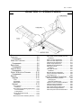
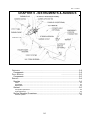
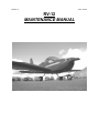
The RV-12 is a single engine, fixed tricycle gear, full-cantilever monoplane. The twoseat cockpit is enclosed with a tip-up windscreen/canopy. The occupants sit side-byside, aft of the engine and forward of the wing spar. Both of the wings are quick
removable. The flaperons remain with the wings and self-connect to the control linkage
when the wings are installed. The empennage consists of a vertical stabilizer, rudder
and stabilator with anti-servo/trim tab.
The airframe is a semi-monocoque aluminum structure, with some steel and
fiberglass parts. Fiberglass composite parts are used to finish some non-structural
portions of the aircraft.
The pilot and passenger board the aircraft from either side using the boarding
step and a reinforced area near the leading edge of the wing. The pilot is seated on the
left side (from within the cockpit) of the aircraft. A combination Electronic Flight
Information System (EFIS) and Engine monitoring System (EMS) with graphical user
interface is used to monitor and report flight and engine performance information to the
pilot.
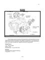
The Rotax 912ULS 100 hp four cylinder engine is enclosed in a fiberglass
composite cowling at the front of the aircraft. Engine power is transferred via an integral
gearbox to the Sensenich composite propeller.
The pilot and the passenger both have full flight and ground controls. Pitch and
roll is controlled from either control stick. The control sticks are linked by push/pull rods
and torque tubes to the flaperons, and linked by cables to a stabilator. The flap lever
controls the flap function of the flaperons. Yaw is controlled using rudder pedals linked
by cables to a traditional rudder that is hinged to a fixed vertical stabilizer. The rudder
pedals have integrated left and right foot pedals that are used to independently control
the wheel brake on the corresponding side.
1-1