1
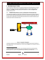
TN-3270 SERVER APPLICATION USER'S MANUAL FOR DT-6XXX EMBEDDED NETWORK PROCESSORS RELEASE.VERSION 13.1 379 Campus Drive, Suite 100 Somerset, NJ 08873 fax: 732 667-1091 phone: 732 667-1080 email: [email protected] http://www.datatekcorp.com D T - 6 X X X TN-3270 Server Application U s e r ' s M a n u a l – R e l e a s e 1 3 . 1 TABLE OF CONTENTS TABLE OF FIGURES AND TABLES ........................................................................ 3 Important Safety Instructions ................................................................................. 4 1 2 INTRODUCTION ................................................................................................. 5 1.1 TN-3270 Server Application (Integrated Configuration)..................................... 5 1.2 TN-3270 Server Application (IP Network Only Configuration)........................... 6 1.3 Variations: Multiple Hosts and Multiple Instances.............................................. 7 TN-3270 Server Application Configuration ...................................................... 8 2.1 DT-6XXX Platform Configuration.......................................................................... 8 2.2 TN-3270 Server Application Configuration .......................................................... 8 2.2.1 2.3 Configuration Planning .................................................................................................. 9 Sample Integrated Configuration ........................................................................10 2.3.1 BNS Node Configuration.............................................................................................. 11 2.3.1.1 UMI Module Configuration.................................................................................... 11 2.3.1.2 SYNC8 (BHI) Configuration .................................................................................. 12 2.3.2 DT-6XXX Configuration ................................................................................................ 13 2.3.2.1 DT-6XXX Platform Configuration ......................................................................... 14 2.3.2.2 TN-3270 Server Application Configuration ......................................................... 14 2.3.3 PC TN-3270 Client ......................................................................................................... 15 2.3.4 Relationships ................................................................................................................ 15 2.4 Sample IP Network Only Configuration ..............................................................16 2.4.1 DT-4000/DT-4180/DT-4280 Configuration ................................................................... 17 2.4.2 DT-6XXX Configuration ................................................................................................ 17 2.4.2.1 DT-6XXX Platform Configuration ......................................................................... 17 2.4.2.2 IP-BHI Application Configuration......................................................................... 18 2.4.2.3 TN-3270 Server Application Configuration ......................................................... 19 2.4.3 PC TN-3270 Client ......................................................................................................... 20 3 Application Commands ................................................................................... 21 3.1 Input Conventions ................................................................................................21 3.2 Login .....................................................................................................................21 3.3 Logout ...................................................................................................................21 3.4 Change Password - chgpass...............................................................................21 3.5 Application Console User Help ...........................................................................21 3.6 Label......................................................................................................................22 3.7 Version - ver..........................................................................................................22 3.8 Configuring BiSync Host Interface Parameters - bsc ........................................22 3.9 Server ....................................................................................................................23 04/13/06 Datatek Applications Inc. 2 D T - 6 X X X TN-3270 Server Application U s e r ' s M a n u a l – R e l e a s e 1 3 . 1 3.10 Timeout ..............................................................................................................23 3.11 Verify Configuration – vfy | vfycfg ...................................................................23 3.12 Display Current Connections – dc | dconn......................................................24 3.13 Display Log - dlog .............................................................................................24 3.14 Display Measurements – dmeas | dm ..............................................................24 3.15 Clear - clr ...........................................................................................................24 4 Application Software Installation & Upgrade ................................................ 25 5 Hardware Warranty .......................................................................................... 26 6 End-User License Agreement for Software ................................................... 26 7 6.1 Software License..................................................................................................26 6.2 Intellectual Property Rights .................................................................................26 6.3 Software Support .................................................................................................27 6.4 Export Restrictions ..............................................................................................27 6.5 Limited Warranty ..................................................................................................27 6.6 No Other Warranties.............................................................................................27 6.7 Special Provisions................................................................................................27 Limitation of Liability....................................................................................... 28 TABLE OF FIGURES AND TABLES FIGURE 1: INTEGRATED CONFIGURATION ....................................................................... 5 FIGURE 2: IP NETWORK ONLY CONFIGURATION ............................................................. 6 FIGURE 3: SAMPLE INTEGRATED CONFIGURATION ........................................................ 10 FIGURE 4: SAMPLE IP-ONLY CONFIGURATION ............................................................. 16 TABLE 1: DMEAS MEASUREMENT CATEGORIES ............................................................ 24 04/13/06 Datatek Applications Inc. 3 D T - 6 X X X TN-3270 Server Application U s e r ' s M a n u a l – R e l e a s e 1 3 . 1 IMPORTANT SAFETY INSTRUCTIONS ! The exclamation point within an equilateral triangle is intended to alert the user to the presence of important operating and maintenance (servicing) instructions in the literature accompanying the product. When installing, operating, or maintaining the DT-6XXX equipment on which this application runs, basic safety precautions should always be followed to reduce the risk of fire, electric shock, and injury to persons, including the following: ! Read and understand all instructions. ! Follow all warnings and instructions marked on this product. ! For information on proper mounting instructions, consult the User’s Manual provided with this product. ! The telecommunications interface should not leave the building premises unless connected to telecommunication devices providing primary and secondary protection. ! This product should only be operated from the type of power source indicated in the User’s Manual. ! This unit is intended to be powered from either –48 V DC or AC voltage sources. See User’s Manual before connecting to the power source. ! The –48 V DC input terminals are only provided for installations in Restricted Access Areas locations. ! Do not use this product near water, for example, in a wet basement. ! Never touch uninsulated wiring or terminals carrying direct current or leave this wiring exposed. Protect and tape wiring and terminals to avoid risk of fire, electric shock, and injury to service personnel. ! To reduce the risk of electrical shock, do not disassemble this product. Service should be performed by trained personnel only. Opening or removing covers and/or circuit boards may expose you to dangerous voltages or other risks. Incorrect re-assembly can cause electric shock when the unit is subsequently used. ! For a unit intended to be powered from –48 V DC voltage sources, read and understand the following: • This equipment must be provided with a readily accessible disconnect device as part of the building installation. • Ensure that there is no exposed wire when the input power cables are connected to the unit. • Installation must include an independent frame ground drop to building ground. Refer to User’s Manual. This symbol is marked on the DT-6XXX, adjacent to the ground (earth) area for the connection of the ground (earth) conductor. ! This Equipment is to be Installed Only in Restricted Access Areas on Business and Customer Premises Applications in Accordance with Articles 110-16, 110-17, and 110-18 of the National Electrical Code, ANSI/NFPA No. 70. Other Installations Exempt from the Enforcement of the National Electrical Code May Be Engineered According to the Accepted Practices of the Local Telecommunications Utility. ! For a unit equipped with an AC Wall Plug-In Unit, read and understand the following: • A DT-6061 unit was tested with the K’TRON, Model KA-52A Wall Plug-In Unit and a DT-6X60 with a Phi Hong Model PSA-30U-240 Wall Plug-In Unit (110-240 V AC to 24 V DC). • Unplug this product from the wall outlet before cleaning. Do not use liquid cleaners or aerosol cleaners. Use a damp cloth for cleaning. • Do not staple or otherwise attach the power supply cord to the building surfaces. • Do not overload wall outlets and extension cords as this can result in the risk of fire or electric shock. • The socket outlet shall be installed near the equipment and shall be readily accessible. • The Wall Plug-In unit may be equipped with a three-wire grounding type plug, a plug having a third (grounding) pin. This plug is intended to fit only into a grounding type power outlet. Do not defeat the safety purpose of the grounding type plug. • Do not allow anything to rest on the power cord. Do not locate this product where the cord may be abused by persons walking on it. • Unplug this product from the wall outlet and refer servicing to qualified service personnel under the following conditions: a) When the powers supply cord or plug is damaged or frayed. b) If liquid has been spilled into the product. c) If the product has been exposed to rain or water. d) If the product does not operate normally by following the operating instructions. Adjust only those controls that are covered by the operating instructions because improper adjustment of other controls may result in damage and will often require extensive work by qualified technician to restore the product to normal operation. e) If the product has been dropped or the cabinet has been damaged. f) If the product exhibits a distinct change in performance. Save These Instructions 04/13/06 Datatek Applications Inc. 4 D T - 6 X X X TN-3270 Server Application U s e r ' s M a n u a l – R e l e a s e 1 3 . 1 1 INTRODUCTION The TN-3270 Server Application that runs on the DT-6XXX family of Embedded Network Processors allows a 3270 client to access a host via a BNS SYNC8 BiSync Host Interface (BHI) module. This Application is designed to replace the TN-3270 DKAP application in either an integrated (BNS network), or a non-BNS (a.k.a. totally IP) network environment. The 3270 client programs are typically resident on a PC. 1.1 TN-3270 SERVER APPLICATION (INTEGRATED CONFIGURATION) The following diagram depicts a configuration involving a 3270 client in an integrated environment. In this environment, a DKAP module running the TN-3270 Server Applications is no longer needed in the node. Instead a DT-6XXX Embedded network Processor is used. A DT-6XXX works either in an IP, frame relay or ATM network. It provides better performance and can handle tremendously more sessions than a DKAP or HS-DKAP module. Node DT-6061 IP U M I TN-3270 Server Application IP Network IP B H I BiSync IP HOST IP PCs with 3270 Client Application Figure 1: Integrated Configuration In the above diagram a 3270 client makes a connection to the BiSync host using the IP address of 1 the DT-6061 plus the TCP port assigned to the TN-3270 server instance that is assigned to that line on the BiSync host. 1 An application instance can be described as a unit of configuration parameters as a specific DT-6XXX application defines them. In other words, each instance of an application is a completely separate process where all aspects of the operation of the application are performed entirely within that process. 04/13/06 Datatek Applications Inc. 5 D T - 6 X X X TN-3270 Server Application U s e r ' s M a n u a l – R e l e a s e 1 3 . 1 Multiple clients call the same IP address and TCP port number. The maximum number of simultaneous clients is a configurable option within the application. The function of the Universal Mediation Interface (UMI) module is to provide the protocol mediation between the BNS network, and the IP network. 1.2 TN-3270 SERVER APPLICATION (IP NETWORK ONLY CONFIGURATION) The TN-3270 Server application may also be used in circumstances where there is no BNS network. DT-6061 IP IP DT-4000 or DT-4180 TN-3270 Server Application & IP-BHI Application IP Network IP IP BiSync HOST PCs with 3270 Client Application Figure 2: IP Network Only Configuration In the above diagram the DT-6061 is actually executing one or more instances of two distinct 2 applications . 1) The first application instance is the TN-3270 Server Application. This is the very same application as in the integrated network case, and the subject of this User's Manual. 2) The second application instance is the BiSync Host Interface (IP-BHI) application. The IP-BHI application interfaces with a BiSync host through a DT-4000, DT-4180, or DT-4280 and performs Cluster Controller emulation for a multi-point host line, thus eliminating the BNS SYNC8 (BHIM) module. 2 The DT-6XXX Platform may support up to 5 simultaneous application types. 04/13/06 Datatek Applications Inc. 6 D T - 6 X X X TN-3270 Server Application U s e r ' s M a n u a l – R e l e a s e 1 3 . 1 1.3 VARIATIONS: MULTIPLE HOSTS AND MULTIPLE INSTANCES Each instance of the TN-3270 Server Application can be configured to distribute clients over multiple BiSync lines connected to one or more BiSync hosts. Each BiSync line must be callable by its own IP address and TCP port number, e.g. via the IP-BHI application or via a UMI module. When multiple hosts are configured, the TN-3270 Server Application allocates new sessions to hosts round robin. If a host fails to answer a call for a new session, it is removed from the round-robin allocation. Any host so removed is periodically monitored until it successfully answers a test call (tried every 70 seconds), whereupon it is made eligible again for allocation to client sessions. Multiple instances of the TN-3270 application may be configured to serve clients using a shared IP address and TCP port. This permits serving up to 3000 clients (up to 30 instances on a single DT3 6061 or DT-6160 each configured with up to 100 clients ) using a single address. The DT-6XXX platform software distributes the calls from the clients to the single address round-robin to the individual instances. The instances must be individually configured so that calls are distributed to the desired set of BiSync lines. 3 A DT-6260 has 48 instances and thus can support up to 4800 clients 04/13/06 Datatek Applications Inc. 7 D T - 6 X X X TN-3270 Server Application U s e r ' s M a n u a l – R e l e a s e 1 3 . 1 2 TN-3270 SERVER APPLICATION CONFIGURATION 2.1 DT-6XXX PLATFORM CONFIGURATION Before proceeding with the configuration of the TN-3270 Server Application, make sure that the DT6XXX Platform has been properly configured and the TN-3270 Server Application is installed on the DT-6XXX Platform. The steps necessary for this are outlined below and are stated in greater detail in the DT-6XXX Platform User's Manual that can be downloaded from the Datatek web site at www.datatekcorp.com. Click on the Support link. Platform Configuration: This command sequence is required for the initial configuration of the DT-6XXX. Platform Software Registration: The platform software must be registered (using the register command) in order to run any applications. Application Installation: This action requires that a host acting as an ftp server is present on a network that is accessible by the DT-6XXX install command. Application Software Registration: The application software must be registered (using the regapp command) in order for it to be enabled. Assignment of an Application to an Instance: The number and type of application must be configured as a system parameter. 2.2 TN-3270 SERVER APPLICATION CONFIGURATION Once the DT-6XXX Platform configuration is complete, instances of the TN-3270 Server Application must be configured. The configuration of the TN-3270 Server application takes place on the application's OA&M port. This OA&M port is accessed by making a Telnet connection to the IP Address of the DT-6XXX that includes the TCP port number of the TN-3270 Server Application instance. The TCP port number of the OA&M port for a particular instance of the TN-3270 Server Application is calculated using the following equation: 10000 + (the application instance # in the DT-6XXX) One TCP session exists per active client. On the client PC, the TCP session is addressed to the TCP port number of an instance of the TN-3270 server application on the DT-6XXX. This is the port that the TN-3270 Server Application uses to listen for an incoming IP call from the client. The default server TCP port number for each instance is calculated using the following equation: 30000 + (( instance # - 1) X 200 ) The server command can be used to change the default TCP port number for an instance, which will allow multiple instances to share a common TCP port number. Typically, a common shared port number is 23, Each instance is configured to connect with one (usually) or more BiSync lines. 04/13/06 Datatek Applications Inc. 8 D T - 6 X X X TN-3270 Server Application U s e r ' s M a n u a l – R e l e a s e 1 3 . 1 2.2.1 CONFIGURATION PLANNING Consider the following planning issues prior to installation and configuration of the DT-6XXX TN-3270 Server Application. ! The number of TN-3270 Client sessions to be allowed for an instance of the TN-3270 server application usually corresponds with the number of terminals in the BHI configuration (either in the BNS SYNC8 BHI modules or in the IP-BHI application) for a particular BiSync line. Where it is desired to pool multiple BiSync lines for use by a client user population, one instance of the TN3270 server application may be configured to call up to 20 different BiSync lines. The TN-3270 server application allows a maximum of 100 client terminals per instance. The default number is sixteen. ! The terminal type to be requested from the TN-3270 client must match. Certain client applications (such as some versions of Hummingbird Exceed) have no provision to configure the 3270 terminal model. Of greater concern is that the terminal model must match what is configured on the BiSync line. A mismatch could cause a serious data error. The TN-3270 Server application will query and set the client for the appropriate terminal type. In the past, this has been defaulted to an “IBM-3278-2” terminal. This is the standard 24x80 terminal type. The TN3270 server allows other terminal types as well. For special circumstances, the TN-3270 server can be configured to accept a secondary terminal type. ! For configuration within the TN-3270 Server Application, consider the IP address of the BHI, and its TCP port for the group of sessions to which a particular BiSync line is attached. • If the BHI is implemented in a BNS SYNC8 module, then this is the IP address of the UMI module and a TCP port number corresponding to the hunt group for a specific set of virtual ports on the UMI. The virtual ports on the UMI specified by this hunt group are configured as “synchronous” virtual ports and have a pre-defined destination to the SYNC8 BHIM group associated with these terminals. • If the BHI is implemented in the IP-BHI application, then the IP address is the address of the DT-6XXX on which the IP-BHI application is resident and the TCP port number is computed using the equation: 30000 + ((instance # - 1) X 200)+ the client group number where a client group number is the number of the group defining a set of logical cluster unit and logical terminals on a BiSync line. 04/13/06 Datatek Applications Inc. 9 D T - 6 X X X TN-3270 Server Application U s e r ' s M a n u a l – R e l e a s e 1 3 . 1 2.3 SAMPLE INTEGRATED CONFIGURATION The following network diagram depicts a generic TN3270 configuration where there is a mixed network of IP elements and BNS. Several network components require configuration. The administrator may need to configure one or more of the following items: 1. BNS Node Configuration • UMI Module • SYNC8 (BHI) Module 2. DT-6061 Configuration • DT-6061 Platform • TN-3270 Server Application 3. PC TN-3270 Client 4. BiSync Host The following sections describe sample configurations for items 1-3 above and are based on the diagram below. Configuration of item number 4 (BiSync Host) is beyond the scope of this document. However, knowledge of the BiSync Host's configuration is required to properly configure the BNS SYNC8 module. TN3270 Instance Number: 1 Base: 30,000 Node DT-6061 with TN-3270 Server Application U M I B H I IP IP 135.17.59.163 IP Network 135.17.59.253 BiSync HOST IP IP PCs with 3270 Client Application Figure 3: Sample Integrated Configuration 04/13/06 Datatek Applications Inc. 10 D T - 6 X X X TN-3270 Server Application U s e r ' s M a n u a l – R e l e a s e 1 3 . 1 2.3.1 BNS NODE CONFIGURATION 2.3.1.1 UMI MODULE CONFIGURATION The UMI can be configured on a BNS/Datakit node by either one of the two ways: 1. As a SAM504, which requires additional configuration on the UMI module itself via the UMI’s OA&M console. This requires two definitions of the same virtual ports, once on the SAM504 and once on the UMI module. 2. As a UMI module only. Beginning with BNS-2000 VCS (Datakit II VCS) Release 6.0, Build 87, the UMI can be configured solely on the BNS node like any other module. Software build 19 or higher must be installed on the UMI module. The examples in the sections below depict the UMI configuration using method 2. Detailed descriptions describing how to configure a UMI can be found in the following documents: 1. UMI User's Manual 2. UMI User's Manual Supplement for BNS/Datakit II VCS Nodes. The overall configuration process for the UMI can be divided into two phases: 1. Base Configuration: setting up the UMI for IP connectivity and console security 2. Operational Configuration: setting up the UMI and BNS node to enable users to make calls between the BNS and IP networks 2.3.1.1.1 UMI - Base Configuration (BNS-2000 VCS Release 6.0 Build 87 and higher) The following console output from a BNS node is the result of the verify umi module command. The results displayed below describe a UMI Base Configuration consistent with the configuration needs of the previous network diagram. CC0> vfy umi mod 19 02-04-17 15:07:22 NODE=WOODY M verify umi module 19 MODULE ADDRESS: 19 MODULE TYPE: umi SERVICE STATE: in DOWNLOAD SERVER: controller VERSION: standard GATEWAY ADDRESS: 135.17.59.1 LOCAL IP ADDR: 135.17.59.253 SNMP IP ADDR: 0.0.0.0 NCHLS: 512 LOCAL SUBMASK: SNMP PORT: 255.255.255.0 0 Datakit is a registered trademark of Lucent Technologies, Inc., licensed to Datatek Applications, Inc., a company independent of Lucent Technologies, Inc. 04/13/06 Datatek Applications Inc. 11 D T - 6 X X X TN-3270 Server Application U s e r ' s M a n u a l – R e l e a s e 1 3 . 1 DNS IP ADDR: vfy umi mod 19 (continued) DNS NAME1: DNS NAME2: DNS NAME3: COMMENT: 2.3.1.1.2 UMI - Operational Configuration The following console output from a BNS node is the result of the verify umi vport command. The results displayed below describe a UMI Operational Configuration consistent with the configuration needs of the network diagram in section 2.3 above. CC0> vfy umi vp 19 1 M 02-04-17 15:08:43 NODE=WOODY verify umi vport 19 1 (Module information which is the same as above) Virtual Port Number 1 to 1 Service State ==> in Service Type ==> ip_to_bns Group ==> 3270orig (This must be an originating group) Protocol ==> synchronous PDD ==> bscm2 (Points to a service name which points to a receive group of virtual terminals defined on a SYNC8 BHI module) Hunt Group Port ==> 14000 CUG list ==> 0 Peer to Peer Encryption ==> Transparent COMMENT UMI vport for TN-3270 service There is one vport defined for each client session that can be active at a time. Each vport is predefined to a service name that points either to a single virtual terminal on a virtual cluster or more realistically to a hunt group of virtual terminals defined on virtual clusters on the SYNC8 (BHI) ports. The hunt group port configured above (14000) on the UMI is the hunt address of virtual ports on the UMI itself to which a TN-3270 client on the user’s PC will connect. This hunt group is different than the group of virtual terminals defined on the SYNC8 module. 2.3.1.2 SYNC8 (BHI) CONFIGURATION The following BNS console output reflects the output of the SYNC8 verify command. The results displayed below describe a bsc3270 configuration consistent with the configuration needs of the previous network diagram. For a more detailed description of how to configure the SYNC8 Module, refer to the BNS-2000 SYNC8 Module Reference Guide. 04/13/06 Datatek Applications Inc. 12 D T - 6 X X X TN-3270 Server Application U s e r ' s M a n u a l – R e l e a s e 1 3 . 1 Note: knowledge of the BiSync Host's configuration is required to properly configure the BNS SYNC8 module This example shows a single virtual cluster controller with three virtual terminals defined in the same receive group. The client PC in the example could be connected to any one of the virtual terminals on the SYNC8 module. CC0> vfy bsc terminal 30 all MODULE ADDRESS: 30 MODULE TYPE: bsc3270 SERVICE STATE: in DOWNLOAD SERVER: controller VERSION: standard HOST PORT 2 MSG CHNLS 6 PORT 2 COMMENT to bsc3270 console PORT CU 2 2 TYPE host TYPE vtam NCHLS: 100 CHNG no CODE SET ebcdic PORT DUPLEX full BAUD RATE 9600 SRVC in SRVC in TERM PORT CU TERM TYPE SCRN SIZE RECV GRP LOGOFF METHOD LOGOFF SEQ ID FWD ACK SRVC 2 1920 bscm2 none N/A no in 2 2 basic BKPL PORT CU TERM CHNL 2 2 1 8 2 2 2 9 2 2 3 15 2.3.2 DT-6XXX CONFIGURATION The DT-6XXX software is composed of two components. One component, called the Platform, exists to support all applications. The second component is comprised of the individual application(s). The Platform provides Operating System functions, selected interfaces, protocol stacks, SNMP functions, and system OA&M while each application uses the services of the resident Platform. 04/13/06 Datatek Applications Inc. 13 D T - 6 X X X TN-3270 Server Application U s e r ' s M a n u a l – R e l e a s e 1 3 . 1 2.3.2.1 DT-6XXX PLATFORM CONFIGURATION The following console output reflects the output of the DT-6XXX vfymod and vfycfg commands. The results displayed below describe a DT-6XXX platform configuration consistent with the configuration needs of the previous network diagram. For a more detailed description of how to configure the DT6XXX platform, refer to the DT-6XXX Platform User's Manual. <tuna: DT-6160> vfy mod module type: DT-6160, Registered hostname: tuna.datatekcorp.com ippublic: 192.168.2.199 status: Active ipother: 192.168.2.99 label: tuna ipaddr: 192.168.2.48 submask: 255.255.255.0 gateway: 192.168.2.1 mac addr: 0.96.10.11.58.123 serial #: 176.61.10.11.58.123 build #: 1.0 rtu #: 5 built on: Thu Apr 22 14:42:15 EDT 2004 booted: 1.07 days ago <tuna: DT-6160> < tuna: DT-6160> vfycfg 1 type=tn3270 2.3.2.2 TN-3270 SERVER APPLICATION CONFIGURATION The following reflects the output of the TN-3270 vfy command based on the configuration input by the bsc command. This output reflects the commands necessary to configure the TN-3270 Server Application so that it is consistent with the configuration needs of the network diagram in Figure 3. <TN3270> bsc dest=135.17.59.253 dport=14000 numsess=50 where dest=IP address of the UMI module dport=TCP port number (This is the hunt group port number on the UMI module.) <TN3270> vfy M Verify TN3270 Instance Configuration Local IP Address: 135.17.59.163, Instance Number: 1 BiSync Host Interface: 135.17.59.253 Port 14000. Number of Sessions: 50 Session Alarm Threshold: 70% 04/13/06 Datatek Applications Inc. 14 D T - 6 X X X TN-3270 Server Application U s e r ' s M a n u a l – R e l e a s e 1 3 . 1 Terminal Type: IBM-3278-2 Secondary Terminal Type: IBM-3279-2 Delay after Host connect: 0 Server TCP Port: 30000 (See the section below on how to determine this value.) Console Inactivity Timeout DISABLED Session Inactivity Timeout DISABLED 2.3.3 PC TN-3270 CLIENT For whatever TN-3270 client is being used, certain configuration parameters must be administered on the client to insure connectivity to the BiSync Host. These parameters are: 1. DT-6XXX IP Address 2. TCP Port Number of the application instance being called Based on the previous network diagram, The DT-6XXX IP Address is 135.17.59.163 . The TCP Port number at the Server is 30000 . The default TCP port number for an instance is a function of the instance in which the application is installed on the DT-6XXX. It is calculated using the following equation: TCP Port Number = 30000 + ((instance # - 1) X 200) The server command can be used to change the default TCP port number. That, in turn, will allow multiple instances to share a common TCP port number. A commonly used, shared TCP port value is 23, which is the standard telnet port value. 2.3.4 RELATIONSHIPS To clarify and summarize the relationship of various TCP ports and hunt group ports for a TN-3270 PC client, the TN-3270 Server Application software, and the UMI module, the following applies: 1. The TCP port to which the TN-3270 PC client is configured to point is the same as the TCP port number that is configured as the server port of one or more instances of the TN-3270 Server Application on the DT-6XXX. The numeric value of this port is either the default calculated by the equation in section 2.3.3 above or overridden by the server command for a particular instance. 2. The TCP port (dport) defined in the BSC command for an instance of the TN-3270 Server Application on the DT-6XXX is the same as the port number defined by the hunt group port (BNS UMI configuration) or vport hport (UMI module configuration) parameter configured on one or more virtual ports on the UMI module. 3. An instance can service several actual BSC host lines where each is defined using the BSC command. Up to 20 host lines can be configured per instance as long as the total aggregate number of terminals is 100 or less. The host lines can be spread over several BiSync hosts or reside on the same host. 04/13/06 Datatek Applications Inc. 15 D T - 6 X X X TN-3270 Server Application U s e r ' s M a n u a l – R e l e a s e 1 3 . 1 2.4 SAMPLE IP NETWORK ONLY CONFIGURATION The following network diagram depicts a generic TN-3270 configuration where there is only an IP network and no BNS. Several network components require configuration. The administrator may need to configure one or more of the following items: 1. DT-4000/DT-4180/DT-4280 2. DT-6XXX Software • DT-6XXX Platform • IP-BHI Application • TN-3270 Server Application 3. PC TN-3270 Client 4. BiSync Host The following sections describe sample configurations for items 1-3 above and are based on the diagram below. Configuration of item number 4 (BiSync Host) is beyond the scope of this document. However, knowledge of the BiSync Host's configuration is required to properly configure the BNS SYNC8 module. D T-6061 w ith TN 3270 A pp lication (instance 21) IP-B H I A pp licatio n (in stan ce 20) IP Netw ork 135.17.59.253 D T-4000 or D T-4180 135.17.59.163 Port 9 B S C H O ST PC s w ith T N3270 Client A pplication. Figure 4: Sample IP-Only Configuration Note that a DT-6XXX with 2 RTU’s or more is required in this configuration since two different applications are residing in the same DT-6XXX. Each application could also reside in different DT6XXX’s. It is the decision of the network administrator/planner what exact configuration is used. 04/13/06 Datatek Applications Inc. 16 D T - 6 X X X TN-3270 Server Application U s e r ' s M a n u a l – R e l e a s e 1 3 . 1 2.4.1 DT-4000/DT-4180/DT-4280 CONFIGURATION A DT-4000, DT-4180, or DT-4280 is used to connect the BiSync host(s) to the IP network. What follows is the output from a DT-4180 console where a BiSync is connected to Port 9. More than one BiSync host can connect to the same DT-4000, DT-4180, or DT-4280. <DT-4180> vfy p 9 Current Configuration for Port 9: Type ==> TCP Port w/Call Origination. Service State ==> In Service. TCP Destination ==> 135.17.59.163 Port 33800 Protocol ==> EBCDIC BiSync. DXE ==> DCE (w/Normal Clocks). Baud Rate ==> 9600 bps. Line Encoding ==> NRZ. Constant Carrier ==> Enabled. Permanently Active ==> Enabled. Peer to Peer Data Encryption ==> Disabled. Comment ==> "to ip-bhi app" A DT-4000/DT-4180/DT-4280 is configured to call the IP-BHI application on a DT-6XXX. The IP address of the DT-6XXX in this example is 135.17.59.163. Each line of one or more BiSync hosts calls its own instance of the IP-BHI application. Conversely, each instance of an IP-BHI application supports only one BiSync host line in a DT-6XXX. In this example, the IP-BHI application is installed on the DT-6XXX in instance 20. Hence the port address configured on the DT-4XXX is determined via the following equation: Port =30000 + ((instance # - 1) X 200) = 30000+((20-1)*200)=33800 Note that a single DT-6061 or DT-6160 can support a combined total of 30 instances of either the IPBHI application and/or TN-3270 server application. A DT-6260 can support 48 instances. 2.4.2 DT-6XXX CONFIGURATION The DT-6XXX software is composed of two components. One component, called the Platform, exists to support all applications. The second component is comprised of the individual application(s). The Platform provides Operating System functions, selected interfaces, protocol stacks, SNMP functions, and system OA&M while each application uses the services of the resident Platform. 2.4.2.1 DT-6XXX PLATFORM CONFIGURATION The following console output reflects the output of the DT-6061 vfymod and vfycfg commands. The results displayed below describe a DT-6061 platform configuration consistent with the configuration 04/13/06 Datatek Applications Inc. 17 D T - 6 X X X TN-3270 Server Application U s e r ' s M a n u a l – R e l e a s e 1 3 . 1 needs of the previous network diagram. For a more detailed description of how to configure the DT6XXX platform, refer to the DT-6XXX Platform User's Manual. <DT-6061> vfymod module type: DT-6061, Registered hostname: test label: none ipaddr: 135.17.59.163 submask: 255.255.255.0 gateway: 135.17.59.1 mac addr: 0.96.29.2.56.87 serial #: 0.0.6.72.97.233 build #: 13.1 rtu #: 2 built on: Thu Apr 22 14:42:15 EDT 2004 booted: 1.07 days ago <DT-6061> vfycfg 20 type=ip_bhi 21 type=tn3270 2.4.2.2 IP-BHI APPLICATION CONFIGURATION For the IP-BHI application itself, only the logical clusters and terminals are defined long with application comments and console labels. The rest of the parameters are the result of the configuration of the DT-6XXX platform. The output of the IP-BHI console is shown below for a vfy bhi. <IP-BHI> vfy bhi M Verify IP-BHI Operation --> Simplex. Instance# --> 20. IP Address --> 135.17.59.163 Console Label --> None Defined. Comments: 1 --> "This is an example" 2 --> "" 3 --> "" BiSync Status: Connected to 135.17.59.253 Port 50009 Code Set --> EBCDIC. EIA Status --> De-Asserted. Host Status --> Inactive. 04/13/06 Datatek Applications Inc. 18 D T - 6 X X X TN-3270 Server Application U s e r ' s M a n u a l – R e l e a s e 1 3 . 1 In the BiSync Status section in the example above, it shows that this instance is connected to the DT-4180 at IP address 135.17.59.253 at port 9 (50009 - 50000 where 50000 is the base for incoming calls on a DT-4000 or DT-4180. The value of 50009 is automatically generated by the IP-BHI application.) In the IP-BHI application, for each instance, logical cluster units and logical terminals must be defined that correspond to the actual physical host’s definition for a BiSync line. The group (grp) command is used to define them. One instance of the IP-BHI application handles only one BiSync line. For more detail, refer to the document DT-6XXX IP-BHI BiSync Host Interface Application User’s Manual which is available for download from the Datatek web site. < IP-BHI> vfy grp 1 M Verify Group 1 Terminal Type: Basic. Screen Size: (M2 - 24 x 80 ) 1920 Characters. Rx Only Attribute: No. Logoff Sequence: None. Host Unavailable Sequence: Connections are prevented. Host becomes available sequence: Connections are allowed. Comment:"" UNITs Assigned: 0.0, 0.1, 0.2, 0.3, 0.4, 0.5, 0.6, 0.7 0.8, 0.9, 0.10, 0.11, 0.12, 1.0, 1.1, 1.2 The example above shows 2 cluster units, one with 13 terminals, and the other with 3, all of which share the same attributes. Additional groups can be defined for this instance defining other clusters and terminals connected to this same BiSync line but with different attributes. There is a maximum of 8 groups and an aggregate total of 64 logical terminals per instance. 2.4.2.3 TN-3270 SERVER APPLICATION CONFIGURATION The following reflects the output of the TN-3270 vfy command based on the configuration input by the bsc command. This output reflects the commands necessary to configure the TN-3270 Server Application so that it is consistent with the configuration needs of the network diagram in Figure 4 <TN3270> bsc dest=135.17.59.163 dport=33801 Where dest=IP address of the DT-6XXX dport=TCP port number (This is the same port number as specified on a DT4000, DT-4180, or DT-4280 for the host line plus the client group number described above.) <TN3270> vfy M Verify TN3270 Instance Configuration Local IP Address: 135.17.59.163, Instance Number: 21 BiSync Host Interface: 135.17.59.163 Port 33801 Number of Sessions: 16 04/13/06 Datatek Applications Inc. 19 D T - 6 X X X TN-3270 Server Application U s e r ' s M a n u a l – R e l e a s e 1 3 . 1 Number of Available Sessions: 0 Session Alarm Threshold: none Terminal Type: IBM-3278-2 Delay after Host connect: 5 Server TCP Port: 34000 Console Inactivity Timeout DISABLED Session Inactivity Timeout DISABLED The server TCP port number (34000 in the above example) is computed using the instance number of the TN-3270 Server Application in the equation below in the next section. This value can be overridden by the server command. One instance of the TN-3270 Server application can support up to 20 host lines. Each host line is configured by specifying corresponding dest and dport parameters. 2.4.3 PC TN-3270 CLIENT For whatever TN-3270 client is being used, certain configuration parameters must be administered on the client to insure connectivity to the BiSync Host. These parameters are: 1. DT-6XXX IP Address 2. TCP Port Number of the application instance being called Based on the previous network diagram in Figure 4. The DT-6061 IP Address is 135.17.59.163. The TCP Port number at the Server is 34000. The default TCP port number for an instance is a function of the instance in which the application is installed on the DT-6XXX. It is calculated using the following equation: TCP Port Number = 30000 + ((instance # - 1) X 200) The server command can be used to change the default TCP port number. That, in turn, will allow multiple instances to share a common TCP port number. A commonly used, shared TCP port value is 23, which is the standard telnet port value. 04/13/06 Datatek Applications Inc. 20 D T - 6 X X X TN-3270 Server Application U s e r ' s M a n u a l – R e l e a s e 1 3 . 1 3 APPLICATION COMMANDS 3.1 INPUT CONVENTIONS All parameters must be given on the command line. Parameters of the form name=<value> may be given in any order. Only the login command might generate a prompt if the passwd=<value> ! Commands may be entered in upper or lower case. ! Parameters of the form name=value may use upper or lower case for name. Default values, if any, are shown in parenthesis as part of the prompt. ! Case is preserved for values. ! When a password is being requested by a prompt, input is not echoed. ! Backspace erases one character and ctrl-U or del (the delete key) deletes the current line of input. 3.2 LOGIN Syntax: login PASSWD=<password> (The default password is “initial”) The login command is used to allow access to the other configuration commands. The PASSWD parameter is not echo suppressed. However, if the PASSWD parameter is not provided, the console prompts for a password; the response is echo-suppressed in this case. Passwords are case sensitive. Upper and lower case letters may be intermixed with digits and other characters. If the password is valid, the user is placed in the logged in mode. Once the console user is logged in, the rest of the commands are accessible. Note: Every application instance might be assigned a different password. 3.3 LOGOUT Syntax: logout The logout command is only allowed if the console user is logged in. It uses no arguments. It will set the console to the logged out mode. 3.4 CHANGE PASSWORD - CHGPASS Syntax: chgpass OLD=<old passwd> NEW=<new> CONFIRM=<new> The chgpass command is used to change a user password on a particular application type. The command is only allowed if the user is logged in. All three parameters must be given on the same line as the command. None of those entries are echo-suppressed. Passwords are case sensitive. Upper and lower case letters must be intermixed. If the current password is valid, and the two entries for the new password match, the password is changed to the new value. 3.5 APPLICATION CONSOLE USER HELP Syntax: help | ? [command] 04/13/06 Datatek Applications Inc. 21 D T - 6 X X X TN-3270 Server Application U s e r ' s M a n u a l – R e l e a s e 1 3 . 1 The help command is always visible. The help command displays the currently allowed commands for the mode that the unit is currently entered. 3.6 LABEL The label command is only allowed when the unit is logged in. Syntax: label [<word> (no spaces) | none | “<string – spaces allowed”] This command enters a label that subsequently appears as part of the system console prompt. Labels can be up to 31 characters long. The label can have embedded blanks if enclosed in double quotes. Labels are case sensitive. The word "none" deletes the label. 3.7 VERSION - VER Syntax: ver The version command is only visible when the application is logged in. The command has no arguments. It displays the current software and database revisions of the application. 3.8 CONFIGURING BISYNC HOST INTERFACE PARAMETERS - BSC Syntax: BSC [dest<n>=<DT-6XXX address of IP-BHI application or UMI IP Address>] [dport<n>=<Computed IP-BHI Application Port number or UMI TCP Hunt Group Port number>] [numsess<n>=<#Sessions>] [ttype=<TERM ID>] [ttype2=<TERM ID>| none] [delay=<seconds>] [almthresh=<% for alarm threshold> | off] The BSC command is only visible when the application is logged in. The command is used to configure the parameters needed for connections to a BiSync Host Interface Application. There is one such connection for each active client. The value of <n> in the dest, dport, and numsess parameters may be 1 to 20. Up to 20 different host links, on the same or different hosts, can be configured for an instance. At least one needs to be configured. If <n> is omitted, 1 is the default; i.e. dest= is the same as dest1=. The dest<n> parameter specifies the IP address of the DT-6XXX containing the IP-BHI application or the IP address of the UMI module. When the dest<n> IP address is the IP-BHI application, the dport<n> parameter value is determined using the equation 30000 + ((instance # - 1) X 200) + the client group number. For further explanation of the client group number, see the DT-6XXX IP-BHI BiSync Host Interface Application User’s Manual. When the dest<n> IP address is the UMI module IP address, the dport<n> parameter is the TCP port of the hunt group for the <n>'th BHI, i.e. UMI module hunt group port, to which the TN-3270 Server makes connections on behalf of its clients. The numsess<n> parameter declares the maximum number of sessions supported by the <n>'th group. The default is sixteen (16). The number of client sessions should match the number of available terminal slots on the BHI. The total of all the configured numsess<n> values is the maximum number of client sessions that will be handled by this instance, and may not exceed 100. To remove a host from the list, execute the following: bsc dest<n>=0.0.0.0 bsc numsess<n>=0 04/13/06 Datatek Applications Inc. 22 D T - 6 X X X TN-3270 Server Application U s e r ' s M a n u a l – R e l e a s e 1 3 . 1 The ttype parameter specifies the terminal type as specified by the host line and the BHI configuration. The TN-3270 server will cycle the client to set this value via the RFC 884 Telnet option sequence. The default value is “IBM-3278-2” which is a 24x80 terminal. Other allowed values are: “IBM-3275-2”, “IBM-3276-2”, “IBM-3276-3”, IBM-3276-4”, “IBM-3277-2”, “IBM-3278-2”, “IBM-3278-3”, “IBM-3278-4”, “IBM-3278-5”, “IBM-3279-2”, and “IBM-3279-3”. For clients that do not cycle properly, the ttype2 parameter may be used to declare an alternate terminal type that the TN-3270 Server Application will accept. The secondary type is accepted after the primary type has been rejected 4 times. This technique may be used IF the client and the BiSync host use a mutual subset of the capabilities of the secondary terminal type. To delete a secondary type, enter ttype2=none. The almthresh parameter declares an alarm threshold, expressed as a percentage of the total available sessions. When the number of active sessions exceeds this percentage, an alarm is reported on the console of the TN-3270 Server Application, if active, or on the DT-6XXX system console. When the number of sessions subsequently drops below 85% of the configured threshold, the alarm is cleared, with a similar console report indicating the condition has cleared. The alarm is disabled by almthresh=off. The delay parameter specifies a number of seconds (from 0 to 10) following the client's initial connection during which messages from the BHI side are dropped instead of being forwarded to the client. After the delay, the “Connected” message is sent. The only purpose for setting a non-zero delay is to configure the TN-3270 Server Application for use with a programmed client and a legacy network in which non-TN3270 messages may originate from the network during call setup. Programbased clients have notorious problems with these non-standard messages. With a delay of 0, the TN3270 Server Application suppresses host messages until the client sends its first message (i.e. the user hits enter). The dc command shows a connection pending delay as “Allocated” instead of “Connected”. 3.9 SERVER Syntax: server [default|<server port number>] The server command is only visible when the application is logged in. The command is used to configure the TCP port number used to accept TN-3270 calls. The default setting will return the TN3270 instance to the default TCP port number associated with that instance based on the formula: 30000 + ((instance # - 1) X 200). 3.10 TIMEOUT Syntax: timeout [console=<seconds> | off] [session=<seconds> | off] The timeout command is only visible when the application is logged in. The command is used to monitor application console inactivity and tn3270 session inactivity. Inactivity is defined as the complete absence of data over the specified period of time. The console parameter sets the inactivity timeout value for the application console. The range of values is 15-254 seconds. The session parameter sets the inactivity timeout value for user sessions. The range of values is 5-3600 seconds. 3.11 VERIFY CONFIGURATION – VFY | VFYCFG Syntax: vfy The vfy command is only visible when the application is logged in. The command is used to display the configured options on the TN-3270 Server application. 04/13/06 Datatek Applications Inc. 23 D T - 6 X X X TN-3270 Server Application U s e r ' s M a n u a l – R e l e a s e 1 3 . 1 3.12 DISPLAY CURRENT CONNECTIONS – DC | DCONN Syntax: dconn The dconn or dc command is used to display all of the current client connections into the TN-3270 Server application. The command will issue a report that shows the connection peer for each active connection. 3.13 DISPLAY LOG - DLOG Syntax: dlog The dlog command is only visible when the application is logged in. This command is used to display the entries in the error log. An exclamation point ( ! ) that precedes a log entry denotes new entries. A double asterisk ( ** ) that precedes a log entry denotes folding of multiple similar entries into a single line. The log file can be cleared with the command: dlog clr 3.14 DISPLAY MEASUREMENTS – DMEAS | DM Syntax: dmeas [SESS <Session #>] The dmeas command is only visible when the application is logged in. The command is used to display currently available measurements on sessions between clients and the host. The SESS < Session #> parameter will limit the display to a particular session number. Session numbers are in the range of one through the maximum allowed per the configuration. The SESS < Session #> parameter is not required to display all sessions with non-zero data. Measurements are only displayed if they are nonzero. The per session measurements available are as follows: Measurement Description Number of Messages from the Client to the Host. Number of Bytes from the Client to the Host. Number of Messages from the Host to the Client. Number of Bytes from the Host to the Client. Number of Empty Messages from the Host to the Client (dropped) 4 Peak Number of Sessions Table 1: Dmeas Measurement Categories 3.15 CLEAR - CLR Syntax: clr The clr command is only visible when the application is logged in. The command is used to clear all measurement tables on sessions between clients and the host. 4 This measurement is suppressed if zero, even when the other measurements are nonzero. 04/13/06 Datatek Applications Inc. 24 D T - 6 X X X TN-3270 Server Application U s e r ' s M a n u a l – R e l e a s e 1 3 . 1 4 APPLICATION SOFTWARE INSTALLATION & UPGRADE An application may be initially installed, or upgraded, using the install and regapp commands on the DT-6XXX console. Release 13.0 and higher must be installed on a DT-6061 running platform software build 16 and higher or on a DT-6160 or DT-6260 with any platform software build. In the DT-6XXX Platform User's Manual, refer to the section titled: “Application Software Installation & Upgrade” 04/13/06 Datatek Applications Inc. 25 D T - 6 X X X TN-3270 Server Application U s e r ' s M a n u a l – R e l e a s e 1 3 . 1 5 HARDWARE WARRANTY The warranty period for the DT-6XXX hardware on which this application runs shall be ninety (90) days from the date of shipment of the hardware from Datatek Applications, Inc. Replacements and repairs are guaranteed for the longer of the remaining original warranty period or 30 days. 6 END-USER LICENSE AGREEMENT FOR SOFTWARE This License Agreement ("License") is a legal contract between you and the manufacturer ("Manufacturer") of the system ("HARDWARE") with which you acquired software product(s) identified above ("SOFTWARE"). The SOFTWARE may include printed materials that accompany the SOFTWARE. Any software provided along with the SOFTWARE that is associated with a separate end-user license agreement is licensed to you under the terms of that license agreement. By installing, copying, downloading, accessing or otherwise using the SOFTWARE, you agree to be bound by the terms of this LICENSE. If you do not agree to the terms of this LICENSE, Manufacturer is unwilling to license the SOFTWARE to you. In such event, you may not use or copy the SOFTWARE, and you should promptly contact Manufacturer for instructions on return of the unused product(s) for a refund. 6.1 SOFTWARE LICENSE You may only install and use one copy of the SOFTWARE on the HARDWARE (unless otherwise licensed by Manufacturer). The SOFTWARE may not be installed, accessed, displayed, run, shared or used concurrently on or from different computers, including a workstation, terminal or other digital electronic device (“Devices”). Notwithstanding the foregoing and except as otherwise provided below, any number of Devices may access or otherwise utilize the services of the SOFTWARE. You may not reverse engineer, decompile, or disassemble the SOFTWARE, except and only to the extent that such activity is expressly permitted by applicable law notwithstanding this limitation. The SOFTWARE is licensed as a single product. Its component parts may not be separated for use on more than one HARDWARE. The SOFTWARE is licensed with the HARDWARE as a single integrated product. The SOFTWARE may only be used with the HARDWARE as set forth in this LICENSE. You may not rent, lease or lend the SOFTWARE in any manner. You may permanently transfer all of your rights under this LICENSE only as part of a permanent sale or transfer of the HARDWARE, provided you retain no copies, you transfer all of the SOFTWARE (including all component parts, the media and printed materials, any upgrades, this LICENSE and, if applicable, the Certificate(s) of Authenticity), and the recipient agrees to the terms of this LICENSE. If the SOFTWARE is an upgrade, any transfer must also include all prior versions of the SOFTWARE. Without prejudice to any other rights, Manufacturer may terminate this LICENSE if you fail to comply with the terms and conditions of this LICENSE. In such event, you must destroy all copies of the SOFTWARE and all of its component parts. 6.2 INTELLECTUAL PROPERTY RIGHTS The SOFTWARE is licensed, not sold to you. The SOFTWARE is protected by copyright laws and international copyright treaties, as well as other intellectual property laws and treaties. You may not copy the printed materials accompanying the SOFTWARE. All title and intellectual property rights in and to the content which may be accessed through use of the SOFTWARE is the property of the respective content owner and may be protected by applicable copyright or other intellectual property laws and treaties. This LICENSE grants you no rights to use such content. All rights not expressly granted under this LICENSE are reserved Manufacturer and its licensors (if any). 04/13/06 Datatek Applications Inc. 26 D T - 6 X X X TN-3270 Server Application U s e r ' s M a n u a l – R e l e a s e 1 3 . 1 6.3 SOFTWARE SUPPORT SOFTWARE support is not provided by Manufacturer, or its affiliates or subsidiaries separate from the HARDWARE. For SOFTWARE support, please contact your supplier of the HARDWARE. SOFTWARE support is limited to the warranty period stated below unless either a separate contract has been consummated between you and the manufacturer or the manufacturer has agreed in writing at the time of purchase by you of the software to an extension of the warranty. Should you have any questions concerning this LICENSE, or if you desire to contact Manufacturer for any other reason, please refer to the address provided in the documentation for the HARDWARE. 6.4 EXPORT RESTRICTIONS You agree that you will not export or re-export the SOFTWARE to any country, person, or entity subject to U.S. export restrictions. You specifically agree not to export or re-export the SOFTWARE: (i) to any country to which the U.S. has embargoed or restricted the export of goods or services, which as of March 1998 include, but are not necessarily limited to Cuba, Iran, Iraq, Libya, North Korea, Sudan and Syria, or to any national of any such country, wherever located, who intends to transmit or transport the products back to such country; (ii) to any person or entity who you know or have reason to know will utilize the SOFTWARE or portion thereof in the design, development or production of nuclear, chemical or biological weapons; or (iii) to any person or entity who has been prohibited from participating in U.S. export transactions by any federal agency of the U.S. government. 6.5 LIMITED WARRANTY Manufacturer warrants that (a) the SOFTWARE will perform substantially in accordance with the accompanying written materials for a period of ninety (90) days from the date of shipment from Datatek Applications, Inc. Software support is limited to the hours of 9 AM to 5 PM ET Monday through Friday excluding Datatek-observed holidays. Other coverage and extended warranty may be purchased at additional cost. Any implied warranties on the SOFTWARE are limited to ninety (90) days. Some states/jurisdictions do not allow limitations on duration of an implied warranty, so the above limitation may not apply to you. Manufacturer's and its suppliers' entire liability and your exclusive remedy shall be, at Manufacturer's option, either (a) return of the price paid, or (b) repair or replacement of the SOFTWARE that does not meet this Limited Warranty and which is returned to Manufacturer with a copy of your receipt. This Limited Warranty is void if failure of the SOFTWARE has resulted from accident, abuse, or misapplication. Any replacement SOFTWARE will be warranted for the remainder of the original warranty period or thirty (30) days, whichever is longer. 6.6 NO OTHER WARRANTIES TO THE MAXIMUM EXTENT PERMITTED BY APPLICABLE LAW, MANUFACTURER AND ITS SUPPLIERS DISCLAIM ALL OTHER WARRANTIES, EITHER EXPRESS OR IMPLIED, INCLUDING, BUT NOT LIMITED TO IMPLIED WARRANTIES OF MERCHANTABILITY, FITNESS FOR A PARTICULAR PURPOSE AND NONINFRINGEMENT, WITH REGARD TO THE SOFTWARE AND THE ACCOMPANYING WRITTEN MATERIALS. THIS LIMITED WARRANTY GIVES YOU SPECIFIC LEGAL RIGHTS. YOU MAY HAVE OTHERS, WHICH VARY FROM STATE/JURISDICTION TO STATE/JURISDICTION. 6.7 SPECIAL PROVISIONS The SOFTWARE and documentation are provided with RESTRICTED RIGHTS. Use, duplication, or disclosure by the United States Government is subject to restrictions as set forth in subparagraph (c)(1)(ii) of the Rights in Technical Data and HARDWARE Software clause at DFARS 252.227-7013 04/13/06 Datatek Applications Inc. 27 D T - 6 X X X TN-3270 Server Application U s e r ' s M a n u a l – R e l e a s e 1 3 . 1 or subparagraphs (c)(1) and (2) of the Commercial HARDWARE Software-Restricted Rights at 48 CFR 52.227-19, as applicable. Manufacturer is Datatek Applications, Inc., 379 Campus Drive, Suite 100, Somerset, NJ 08873. If you acquired the SOFTWARE in the United States of America, this Software License are governed by the laws of the State of New Jersey, excluding its choice of laws provisions. If you acquired the SOFTWARE outside the United States of America, local law may apply. This LICENSE constitutes the entire understanding and agreement between you and the Manufacturer in relation to the SOFTWARE and supercedes any and all prior or other communications, statements, documents, agreements or other information between the parties with respect to the subject matter hereof. 7 LIMITATION OF LIABILITY To the maximum extent permitted by applicable law, in no event shall Manufacturer or its suppliers be liable for any damages whatsoever (including without limitation, special, incidental, consequential, or indirect damages for personal injury, loss of business profits, business interruption, loss of business information, or any other pecuniary loss) arising out of the use of or inability to use this product, even if Manufacturer has been advised of the possibility of such damages. In any case, Manufacturer's and its suppliers' entire liability under any provision of this License shall be limited to the amount actually paid by you for the SOFTWARE and/or the HARDWARE. Because some states/jurisdictions do not allow the exclusion or limitation of liability for consequential or incidental damages, the above limitation may not apply to you. ©Copyright 2000, 2002 TeleComp, Inc. ©Copyright 2002, 2006 TeleComp Research and Development Corporation ©Copyright 2000, 2006 Datatek Applications, Inc. All Rights Reserved Printed in USA 04/13/06 Datatek Applications Inc. 28