1
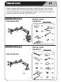
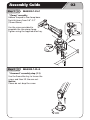
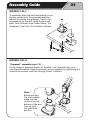
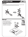
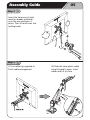
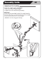
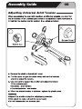
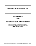
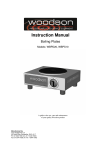
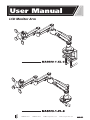
User Manual
LCD Monitor Arm
T 800 463-7731
F 800 461-3182
[email protected]
www.ise-ergonomics.com
01
Check-List
Before assembly please spend some time to read this and follow the procedures step by step. Do not discard any of the packaging until you have
checked all the parts and the package of fittings. If you are missing any of
the parts, please contact ISE Customer Service.
MA5000-1-xl-C
Part Check-List
MA5000-1-xl-G
Part Check-List
Fitting / Tools
Check-List
Fitting / Tools
Check-List
Assembly Guide
Step 1
MA5000-1-xl-C
“Clamp” assembly
Adhere the pad to the clamp base.
Desk thickness from 0.6”-3.3”
(15mm-85mm).
Use the screws provided to
assemble the two-piece clamp.
Tighten using the supplied allen key.
Step 2
MA5000-1-xl-G
“Grommet” assembly step (1-1)
Use the 2mm allen key to loosen the
screw, and then lift the arm out.
Notice:
Please do not drop the screw.
02
Assembly Guide
03
MA5000-1-xl-C
To assemble, place the small metal plate in the
bottom concavity of the grommet and then
adhere the pad to the grommet. Then fix the
grommet set on the desk using the bolt and
parts. Desk thickness from 20mm-50mm. The
diameter of the hole is from 20mm to 50mm.
MA5000-1-xl-G
“Grommet” assembly step (1-3)
Fix the clamp or grommet mount on the desk. Use 2 mm allen key to secure the pole and the clamp or grommet mount together, by tightening the
screw at the bottom, and then turning it back 1 rotation.
Note:
Before securing
the screw please
make sure the
concavity on the
bottom of the arm
lines up with
the small hole
position.
Assembly Guide
04
Step 2
Pull the locking knob out and then drop the lever down to open the Vesa
mount, and then remove the Vesa mount from the arm.
Step 3
Place LCD face down on a flat
surface. Place Vesa mount
on the LCD back and align to
the screw holes. Secure them
together with four screws and
then tighten them up with
screwdriver (not provided).
Assembly Guide
05
Step 4
Insert the Vesa mount (with
monitor already attached)
onto the arm and press it
down. Then lift and insert the
locking knob.
Step 5
(1) Use cable clip supplied to
finish cable management.
(2) Slide the clear plastic cable
wing forward to open. Insert
cables and lift to close.
Assembly Guide
Adjustment For Loading
Caution for weight capacity adjustment:
1. Make sure of the LCD panel weight.
2. Support arm with a hand during assembly.
Adjustment:
Use the Allen key provided to adjust the weight capacity.
Twist the Allen key in a clockwise direction for less weight;
counterclockwise direction for more weight.
• MA5000-1-XL-C/G: 4-9 kg (8.8-19.8 lbs)
06
Assembly Guide
08