1
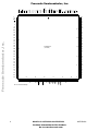
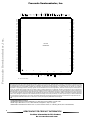
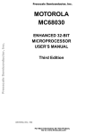
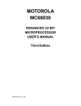
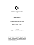
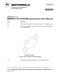
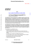
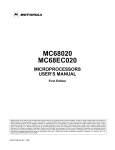
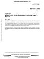
Freescale Semiconductor, Inc.
Order this document
by MC68EC030UMAD/AD
REV 2
MC68EC030
Addendum
Freescale Semiconductor, Inc...
MC68EC030 32-Bit Embedded Controller User's
Manual
April 17, 1996
This addendum to the initial release of the MC68EC030 User's provides additional information not included
in the original (or corrections to the original text). This document and other information on this product is
maintained on the AESOP BBS, which can be reached at (800) 843-3451 (from the U.S. and Canada) or
(512) 891-3650. Configure modem for up to 14.4 Kbaud, 8 bits, 1 stop bit, and no parity. Terminal software
should support VT100 emulation. Internet access is provided by telneting to pirs.aus.sps.mot.com
[129.38.233.1] or through the World Wide Web at http://pirs.aus.sps.mot.com.
Incorporate the following information into the manual. This addendum contain information on junction
temperatures for the pin grid array package and 132-lead ceramic surface mount package. A pinout and the
case package is also given for the 132-lead ceramic surface mount and 144-lead TQFP (PV Suffix)
package.
This document contains information on a product under development. Motorola reserves the right to change or discontinue this product without notice.
SEMICONDUCTOR PRODUCT INFORMATION
© MOTOROLA 1996
For More Information On This Product,
Go to: www.freescale.com
Freescale Semiconductor, Inc.
The following tables define the maximum junction temperature for the PPGA and FE packages for the
MC68EC030.
Maximum Junction Temperature for PPGA Package
TJ Max. = 115 °C
Maximum ambient temperature (°C) vs. airflow and rated frequency—PPGA without heatsink.
Freescale Semiconductor, Inc...
Frequency
MHz
PD Max. at TJ
Max. Watts
Air Flow in linear feet/minute
0*
100
200
400
500
40
1.55
65
72
75
79
81
33.33
1.40
70
76
79
83
84
25
1.25
75
80
83
86
88
20
1.15
78
83
85
89
90
16.67
1.10
80
84
86
90
91
Typical junction temperature (°C) for operations at TA Max. above—PPGA without heatsink.
Frequency
MHz
PD Typical
Watts
Air Flow in linear feet/minute
0*
100
200
400
500
40
0.95
96
98
99
101
102
33.33
0.85
97
100
101
102
103
25
0.75
99
101
102
104
104
20
0.65
99
101
102
104
104
16.67
0.60
99
101
102
104
104
Maximum Power Dissipation vs. Frequency—PPGA Package
Frequency
MHz
PD Max. at
TA = 0° Watts
40
1.80
33.33
1.60
25
1.40
20
1.30
16.67
1.20
Theta JA vs. Airflow—PPGA Package without heatsink (estimated)
Air Flow in linear feet/minute
0*
32
* Natural Convection
2
100
200
400
500
28
26
23
22
MC68EC030 USER MANUAN ADDENDUM
For More Information On This Product,
Go to: www.freescale.com
MOTOROLA
Freescale Semiconductor, Inc.
Maximum Junction Temperature for FE package—without heatsink
TJ Max. = 115 °C
Maximum ambient temperature (°C) vs. airflow and rated frequency—FE without heatsink.
Freescale Semiconductor, Inc...
Frequency
MHz
PD Max. at TJ
Max. Watts
Air Flow in linear feet/minute
0*
100
200
400
500
40
1.55
44
61
72
76
78
33.33
1.40
51
66
76
80
81
25
1.25
58
71
80
84
85
20
1.15
62
75
83
86
87
16.67
1.10
64
77
84
88
89
Typical junction temperature (°C) for operations at TA Max. above—FE without heatsink.
Frequency
MHz
PD Typical
Watts
Air Flow in linear feet/minute
0*
100
200
400
500
40
0.95
87
94
98
100
101
33.33
0.85
90
96
100
101
102
25
0.75
92
98
101
103
103
20
0.65
92
98
101
103
103
16.67
0.60
92
98
101
103
103
Maximum Power Dissipation vs. Frequency—FE Package
Frequency
MHz
PD Max. at
TA = 0° Watts
40
1.80
33.33
1.60
25
1.40
20
1.30
16.67
1.20
Theta JA vs. Airflow—FE Package without heatsink (estimated)
Air Flow in linear feet/minute
0*
46
* Natural Convection
MOTOROLA
100
200
400
500
35
28
25
24
MC68EC030 USER MANUAN ADDENDUM
For More Information On This Product,
Go to: www.freescale.com
3
Freescale Semiconductor, Inc.
Maximum Junction Temperature for FE package—with heatsink
TJ Max. = 115 °C
Maximum ambient temperature (°C) vs. airflow and rated frequency—FE with heatsink.
Freescale Semiconductor, Inc...
Frequency
MHz
PD Max. at TJ
Max. Watts
Air Flow in linear feet/minute
0*
100
200
400
500
40
1.55
61
76
84
86
87
33.33
1.40
66
80
87
88
90
25
1.25
71
84
90
91
93
20
1.15
75
86
92
93
94
16.67
1.10
77
88
93
94
95
Typical junction temperature (°C) for operations at TA Max. above—FE with heatsink.
Frequency
MHz
PD Typical
Watts
Air Flow in linear feet/minute
0*
100
200
400
500
40
0.95
94
100
103
104
104
33.33
0.85
96
101
104
105
105
25
0.75
98
103
105
106
106
20
0.65
98
103
105
106
106
16.67
0.60
98
103
105
106
106
Maximum Power Dissipation vs. Frequency—FE Package
Frequency
MHz
PD Max. at
TA = 0° Watts
40
1.80
33.33
1.60
25
1.40
20
1.30
16.67
1.20
Theta JA vs. Airflow—FE Package with heatsink (estimated)
Air Flow in linear feet / minute
0*
35
* Natural Convection
100
200
400
500
25
20
19
18
The following figures provide a pinout and the mechanical dimensions for the 132-Lead Surface Mount (FE
Suffix) and 144-Lead Thin Quad Flat Pack TQFP (PV Suffix).
4
MC68EC030 USER MANUAN ADDENDUM
For More Information On This Product,
Go to: www.freescale.com
MOTOROLA
Freescale Semiconductor, Inc.
FE SUFFIX PACKAGE
CASE 831-01
S
0.20 (0.008)
M
T X S —YS
0.51 (0.020)
M
T X S —Y S
ZS
A
Z S
PIN ONE INDENT
Freescale Semiconductor, Inc...
G
V
L
B
Y
X
Z
0.51 (0.020)
0.20 (0.008)
M
M
T X S —Y S
T X S —Y S
ZS
Z S
R
J
W
∩ 0.10 (0.004)
T SEATING PLANE
C
M
D 132 PL
0.20 (0.008)
DIM
A
B
C
D
G
H
J
K
L
M
R
S
V
MOTOROLA
H
MILLIMETERS
MIN
MAX
21.85
22.86
21.85
22.86
3.94
4.31
0.204
0.292
0.64 BSC
0.64
0.88
0.13
0.20
0.51
0.76
20.32 REF
8°
0°
0.64
27.31
27.55
27.31
27.55
INCHES
MIN
MAX
0.860
0.900
0.860
0.900
0.155
0.170
0.0080 0.0115
0.025 BSC
0.025
0.035
0.005
0.008
0.020
0.030
0.800 REF
0°
8°
0.025
1.075
1.085
1.075
1.085
G
M
T X S —YS
ZS
K
NOTES:
1. DIMENSIONING AND TOLERANCING PER ANSI Y14.5M, 1982.
2. CONTROLLING DIMENSION: INCH
3. DIM A AND B DEFINE MAXIMUM CERAMIC BODY DIMENSIONS
INCLUDING GLASS PROTRUSION AND MISMATCH OF CERAMIC
BODY TOP AND BOTTOM.
4. DATUM PLANE -W- IS LOCATED AT THE UNDERSIDE OF LEADS
WHERE LEADS EXIT PACKAGE BODY.
5. DATUMS X-Y AND Z TO BE DETERMINED WHERE CENTER LEADS
EXIT PACKAGE BODY AT DATUM -W-.
6. DIM S AND V TO BE DETERMINED AT SEATING PLANE, DATUM -T-.
7. DIM A AND B TO BE DETERMINED AT DATUM PLANE -W-.
MC68EC030 USER MANUAN ADDENDUM
For More Information On This Product,
Go to: www.freescale.com
5
1
5
CIIN
DBEN
SIZ0
SIZ1
ECS
R/W
CBACK
CDREQ
AS
DS
GND
VCC
VCC
DSACK0
GND
GND
DSACK1
STERM
BERR
HALT
10
VCC
17
AVEC
CLK
GND
FC1
FC2
VCC
GND
BR
BGACK
BG
CIOUT
OCS
RMC
FCO
GND
Freescale Semiconductor, Inc.
117
125
A0
D29
D28
A1
A31
A30
GND
110
25
A29
D24
A27
Freescale Semiconductor, Inc...
105
30
VCC
D23
A25
D22
A24
D21
D20
A23
A22
GND
A21
A20
MC68EC030 FE
(TOP VIEW)
35
100
D17
D16
A18
A17
95
GND
D15
40
D14
A16
A15
D13
A14
D12
GND
A13
A12
GND
D19
D18
A19
90
45
GND
D11
D10
A11
D9
A10
VCC
D8
VCC
80
REFILL
STATUS
D0
D1
GND
D2
D3
D4
D5
D6
VCC
VCC
75
70
RESET
NC
GND
GND
IPL2
IPL1
IPL0
CDIS
NC* - Do not connect to this pin.
65
60
IPEND
A9
55
MC68EC030 USER MANUAN ADDENDUM
For More Information On This Product,
Go to: www.freescale.com
83
NC*
D7
50
A8
A7
A6
A5
A4
GND
A3
A2
GND
NC*
NC*
6
GND
D27
D26
D25
A28
A26
VCC
VCC
VCC
D31
D30
MOTOROLA
Freescale Semiconductor, Inc.
CASE 918-02
144 TQFP
0.20 (0.008) H L– M N
0.20 (0.008) H L– M N
144
109
P
L, M, N
108
1
CL
G
DETAIL "A"
B V
DETAIL "B"
Freescale Semiconductor, Inc...
F
AA
J
B1 V1
DETAIL "A"
BASE METAL
36
M
N
72
37
A1
S1
NOTES:
A
S
C
θ2
DETAIL "C"
H
∩ 0.08 (0.003)
T SEATING
PLANE
DETAIL "B"
C2
0.05 (0.005)
S
θ
R2
R1
0.25 (0.010)
GAGE PLANE
K
E
C1
Y
DETAIL "C"
Z
θ1
1. DIMENSIONING AND TOLERANCING PER ANSI
Y14.5M, 1982.
2. CONTROLLING DIMENSION: MILLIMETER.
3. DATUM PLANE -H- IS LOCATED AT BOTTOM OF
LEAD AND COINCIDENT WITH THE LEAD WHERE
THE LEAD EXITS THE PLASTIC BODY AT THE
BOTTOM OF THE PARTING LINE.
4. DATUMS -L-, -M-, AND -N- TO BE DETERMINED AT
DATUM PLANE -H-.
5. DIMENSIONS S AND V TO BE DETERMINED AT SEATING
PLANE -T-.
6. DIMENSIONS A AND B DO NOT INCLUDE MOLD PROTRUSION.
ALLOWABLEPROTRUSION IS 0.25 (0.010 PER SIDE.
DIMENSIONS A AND B DO NOT INCLUDE MOLD
MISMATCH AND ARE DETERMINED AT DATUM LINE -H-.
7. DIMENSION D DOES NOT INCLUDE DAMBAR PROTRUSION.
ALLOWABLEDAMBAR PROTRUSION SHALL NOT CAUSE
THE D DIMENSION TO EXCEED 0.35 (0.014).
DIM
A
A1
B
B1
C
C1
C2
D
E
F
G
J
K
P
R1
R2
S
S1
V
V1
Y
Z
AA
θ
θ1
θ2
MOTOROLA
D
(ROTATED 90°)
144 PL
0.08(0.003) M T L – M
73
MILLIMETERS
MIN
MAX
20.00 BSC
10.00 BSC
20.00 BSC
10.00 BSC
1.60
1.40
0.15
0.05
1.45
1.35
0.27
0.17
0.75
0.45
0.23
0.17
0.50 BSC.
0.20
0.09
0.50 REF
0.25 BSC
0.20
0.13
0.20
0.13
22.00 BSC
11.00 BSC
22.00 BSC
11.00 BSC
0.25 REF
1.00 REF
0.16
0.09
0°
7°
0°
11°
13°
MC68EC030 USER MANUAN ADDENDUM
For More Information On This Product,
Go to: www.freescale.com
INCHES
MIN
MAX
0.790 BSC
0.394 BSC
0.790 BSC
0.394 BSC
0.055 0.063
0.002 0.006
0.053 0.057
0.007 0.011
0.018 0.030
0.007 0.009
0.20 BSC.
0.004 0.008
0.020 REF
0.010 BSC
0.005 0.008
0.005 0.008
0.866 BSC
0.433 BSC
0.866 BSC
0.433 BSC
0.010 REF
0.039 REF
0.004 0.006
0°
0°
7°
11°
13°
7
109
NC*
V CC
110
R/W
SIZ1
ECS
SIZ0
DBEN
GND
CIIN
DS
AS
CBACK
BERR
HALT
VCC
STERM
CBRQ
80
85
90
NC*
NC*
95
DSACK1
GND
GND
DSACK0
GND
VCC
CLK
VCC
AVEC
FC2
100
105
NC*
FC1
FC0
GND
RMC
OCS
BG
CIOUT
NC*
BGACK
Freescale Semiconductor, Inc.
75
73
NC*
NC*
70
BR
D30
A0
A1
115
D29
65
A31
A30
D28
GND
GND
D27
A29
D26
A28
120
D25
60
A27
A26
V CC
A24
D22
D21
125
TOP VIEW
MC68EC030PV
A23
A22
55
D20
GND
D19
GND
A21
A20
D24
V CC
D23
A25
D18
D17
130
A19
50
D16
A18
GND
A17
D15
D14
D13
A16
A15
135
A14
45
GND
A11
140
D9
A10
V CC
40
D8
V CC
37
NC*
NC*
NC*
NC*
D7
D5
D6
35
D3
D4
GND
D1
D0
STATUS
CDIS
VCC
IPL0
D2
30
25
IPL1
IPL2
GND
GND
NC*
20
REFILL
15
VCC
RESET
A4
GND
A5
A7
10
A6
A9
A8
5
A3
A2
GND
NC*
IPEND
144
1
NC*
NC*
D12
GND
D11
D10
A13
A12
NC*
Freescale Semiconductor, Inc...
V CC
V CC
D31
GND
NC*—Do not connect to this pin.
Motorola reserves the right to make changes without further notice to any products herein. Motorola makes no warranty, representation or guarantee regarding
the suitability of its products for any particular purpose, nor does Motorola assume any liability arising out of the application or use of any product or circuit, and
specifically disclaims any and all liability, including without limitation consequential or incidental damages. "Typical" parameters can and do vary in different
applications. All operating parameters, including "Typicals" must be validated for each customer application by customer's technical experts. Motorola does not
convey any license under its patent rights nor the rights of others. Motorola products are not designed, intended, or authorized for use as components in
systems intended for surgical implant into the body, or other applications intended to support or sustain life, or for any other application in which the failure of the
Motorola product could create a situation where personal injury or death may occur. Should Buyer purchase or use Motorola products for any such unintended
or unauthorized application, Buyer shall indemnify and hold Motorola and its officers, employees, subsidiaries, affiliates, and distributors harmless against all
claims, costs, damages, and expenses, and reasonable attorney fees arising out of, directly or indirectly, any claim of personal injury or death associated with
such unintended or unauthorized use, even if such claim alleges that Motorola was negligent regarding the design or manufacture of the part. Motorola and
are registered trademarks of Motorola, Inc. Motorola, Inc. is an Equal Opportunity/Affirmative Action Employer.
Literature Distribution Centers:
USA/EUROPE: Motorola Literature Distribution; P.O. Box 20912, Arizona 85036. 1-800-441-2447
JAPAN: Nippon Motorola Ltd.; 4-32-1, Nishi-Gotanda, Shinagawa-ku, Tokyo 141 Japan.
HONG KONG: Motorola Semiconductors H.K. Ltd.; Silicon Harbour Center, No. 2 Dai King Street, Tai Po Industrial Estate,
SEMICONDUCTOR PRODUCT INFORMATION
For More Information On This Product,
Go to: www.freescale.com