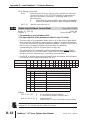
1
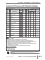
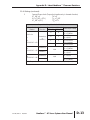
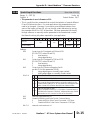
LATEST
SURESERVO™
FIRMWARE REVISIONS
APPENDIX
D
B
In This Appendix...
SureServo Firmware Identification . . . . . . . . . . . . .D–2
Overview of Changes in New Firmware Versions . .D–2
Firmware Version 2.105 . . . . . . . . . . . . . . . . . . . . . . . . . . . . . . .D–2
Firmware Version 2.10 . . . . . . . . . . . . . . . . . . . . . . . . . . . . . . . .D–2
Drive Operation Changes in Firmware Version 2.10
. . . . . . . . . . . . . . . . . . . . . . . . . . . . . . . . . . . . . . .D–2
Summary of Firmware v2.10 Parameter Changes .D–3
Detailed Parameter Listings . . . . . . . . . . . . . . . . . .D–4
Appendix D: Latest SureServo™ Firmware Revisions
SureServo™ Firmware Identification
You can determine the firmware version of your SureServo drive by reading P0-00.
Overview of Changes in New Firmware Versions
Firmware Version 2.105
• P0.18: Added new parameter, “Servo On Time Record”
Firmware Version 2.10
SureServo firmware version v2.10 includes the following changes:
• Reset active fault from keypad
• Torque limit function
• P0-02: Changed parameter setting 05
• P0-17: Added Output Functions Status [new parameter]
• P1-33: New parameter settings 7 and 8
• P1-56: Added Overload Output Warning Threshold [new parameter]
• P2-10~P2-17: Changed parameter setting 06
• P2-18~P2.22: New parameter setting 10
• P2-32: Changed parameter default setting
• P2-64: Added Advanced Torque Limit Mode [new parameter]
• P2-65: Added Special Input Functions [new parameter]
• P3-08: Added Digital Input Software Control Mask [new parameter]
• P4-07: Changed parameter resolution
Drive Operation Changes in Firmware Version 2.10
Reset Active Fault from Keypad
Active faults can now be reset from the keypad. Press and hold the UP and
DOWN Arrow Keys simultaneously for two seconds to clear the fault.
Torque Limit Function
Torque limits are now always in effect whenever they are programmed to do so by
using P1-02 and/or P1-12~P1-14. This includes the torque limits being in effect
during the homing operation. With previous firmware, the torque limits were not
effective until after the homing operation was completed.
D–2
SureServo™ AC Servo Systems User Manual
2nd Ed, Rev B
08/2011
Appendix D: Latest SureServo™ Firmware Revisions
Summary of Firmware v2.10 Parameter Changes
P0-00
1 Firmware Version
P0-02
-
0
0002 40003
2
setting 05
corrected
-
0
0011 40018
21
new
parameter
-
0
0121 40290
441
new settings
7~8
% 120
0138 40313
470
new
parameter
- varies
020A 40523 1012 setting 06
~0211 ~40530 ~1021 corrected
- varies
0212 40531 1022 new setting
~0216 ~40535 ~1026 x10
Y Y Y 0~5
-
0
0220 40545 1040
default setting
changed to 0
-
0
0240 40577 1100
new
parameter
Y Y Y 0~16
Y Y Y
1
Output Functions Status
(Read Only)
P1-33
3
Position Control Mode
Y (when using internal indexer)
0~
1FF [h]
- 0~8
Y Y Y 0~120
P2-10 6 Digital Input Terminal 1~8
Y Y Y 0~145
(DI1~DI8)
~P2-17
P2-18 6 Digital Output Terminal 1~5 Y Y Y 0~110
(DO1~DO5)
~P2-22
P2-32
2 Tuning Mode
Change
Mdbs
Octal
Dec
now reads
v2.103
Drive Status (Front Panel
Display)
Overload Output
Warning Threshold
Hex
0
P0-17
P1-56
Addresses
- varies 0000 40001
Y Y Y
(factory
set)
Default
P V T
Units
Description
Control
Mode
Range
Note
Parameter
Parameters Changed in Firmware v2.10
P2-64
Advanced Torque Limit
Mode
Y Y - 0~3
P2-65
Special Input Functions
Y Y Y
0~
bit
FFFF [h]
0
0241 40578 1101
new
parameter
P3-08
Digital Input Software
Control Mask
Y Y Y
0~
bit
FFFF [h]
0
0308 40777 1410
new
parameter
P4-07
Input Status
Y Y Y
0~
bit
FFFF [h]
0
0404 41032 2007
parameter
now 16 bits
Notes:
1) Read-only register.
2) Parameter cannot be set when the servo drive is enabled.
3) Parameter is effective only after power to the servo drive has been cycled.
4) Parameter setting not written to drive flash memory; not retained when power is off.
5) Parameter does not return to factory default when P2-08 is set to 10.
6) Parameter may or may not return to factory default when switching control modes,
depending upon P1-01 setting.
7) Block Transfer Parameters must be entered from the drive keypad.
Control Mode Abbreviations:
P: Position control mode
T: Torque control mode
V: Velocity control mode
Parameter values are in decimal format unless otherwise indicated by “h” for
hexadecimal.
2nd Ed, Rev B
08/2011
SureServo™ AC Servo Systems User Manual
D–3
Appendix D: Latest SureServo™ Firmware Revisions
Detailed Parameter Listings
Parameter Notes:
1) Read-only register.
2) Parameter cannot be set when the servo drive is enabled.
3) Parameter is effective only after power to the servo drive has been cycled.
4) Parameter setting not written to drive flash memory; not retained when power is off.
5) Parameter does not return to factory default when P2-08 is set to 10.
6) Parameter may or may not return to factory default when switching control modes,
depending upon P1-01 setting.
7) Block Transfer Parameters must be entered from the drive keypad.
Parameter values are in decimal format unless otherwise indicated by “h” for
hexadecimal.
P0-02
Drive Status (front panel display)
Range: 0 ~ 16
Default: 0
Mem Addr: 0002[h]
Units: various
Control Modes: P/V/T
* Setting 05 is corrected in firmware v2.10 to display the input frequency of the
pulse command in 0.1kHz units. (The previous firmware displayed rpm instead.)
• This parameter shows the servo drive status.
Settings:
D–4
00
01
02
03
04
*05
06
07
08
09
10
11
12
13
14
Motor feedback - absolute position (counts) (10,000 counts = 1 rev)
Motor feedback - absolute position (revs)
Position command (counts)
Position command (revs)
Position error (counts)
Input frequency of pulse command (0.1kHz)
Actual motor velocity (rpm)
Velocity input command (V)
Velocity input command (rpm)
Torque input command (V)
Torque input command (%)
Current load (% of rated torque)
Peak load (% of rated torque since powerup)
Bus voltage
Ratio of load inertia to motor inertia (Jl/Jm)
15
16
Motor feedback - captured position (counts)
Motor feedback - captured position (revs)
SureServo™ AC Servo Systems User Manual
2nd Ed, Rev B
08/2011
Appendix D: Latest SureServo™ Firmware Revisions
[1] Output Functions Status
P0-17
Mem Addr: 0011[h]
Range: 0 ~ 1FF [h]
Default: 0
Units: n/a
Control Modes: P/V/T
• This parameter is new in firmware v2.10.
• This parameter allows you to read the status of all DO Functions via MODBUS
communications, regardless of whether or not they are assigned to physical
digital outputs (DO1~DO5).
DO Functions Indications:
bit 0
bit 1
bit 2
bit 3
bit 4
bit 5
bit 6
bit 7
bit 8
bit 9~15
Servo Ready (no faults)
Servo On (enabled)
At Zero Velocity
At Velocity Reached
At Position
At Torque Limit
At Overload Output Warning Threshold
Active Fault
Electromagnetic Brake Control
reserved
[1][5] Servo On Time Record
P0-18
Mem Addr: 0012[h]
Range: 0 ~ 65,535
Units: hr
Default: 0
Control Modes: P/V/T
• This parameter is new in firmware v2.105.
• This parameter stores and displays the total time that the servo drive is ON.
It is written to EEPROM once per hour.
2nd Ed, Rev B
08/2011
SureServo™ AC Servo Systems User Manual
D–5
Appendix D: Latest SureServo™ Firmware Revisions
P1-33
[3] Position Control Mode (Internal Indexer)
Range: 0 ~ 8
Default: 0
Mem Addr: 0121[h]
Units: n/a
Control Modes: Pr
* Settings 7 and 8 are new with firmware v2.10.
• This parameter determines the specific type of control when using Pr control
mode (P1-01) with the internal indexer. (Refer to Chapter 5 for explanation and
examples of Index Mode and internal position indexing.)
Settings:
D–6
0
Absolute Position Mode (Absolute Positioning):
The system will move to new positions based on the values set in P115 ~ P1-30, which are interpreted as target positions referenced from
the home position.
1
Incremental Position Mode (Incremental Positioning):
The system will move to new positions based on the values set in P115 ~ P1-30, which are interpreted as distances to move from the
current position.
2
Forward Operation Index Mode:
The system will go to the programmed index position only in the
forward direction.
3
Reverse Operation Index Mode:
The system will go to the programmed index position only in the
reverse direction.
4
Shortest Path Index Mode:
The system will go to the programmed index position by determining
and using the shortest path and direction.
5
Absolute Auto Position Mode:
The system will move to new positions, referenced from the home
position, based on the Auto Position Mode internal function. The Auto
Position Mode DI (setting 42 of P2-10~P2-17) acts as a level trigger for
this move.
6
Incremental Auto Position Mode
The system will move to new positions, referenced from the current
position, based on the Auto Position Mode internal function. The Auto
Position Mode DI (setting 42 of P2-10~P2-17) acts as a level trigger for
this move.
*7
Absolute One-Cycle Auto-Running Mode:
This setting operates the same as setting #5, except that the DI acts as
an edge trigger, and initiates only one cycle.
*8
Incremental One-Cycle Auto-Running Mode:
This setting operates the same as setting #6, except that the DI acts as
an edge trigger, and initiates only one cycle.
SureServo™ AC Servo Systems User Manual
2nd Ed, Rev B
08/2011
Appendix D: Latest SureServo™ Firmware Revisions
Overload Output Warning Threshold
P1-56
Range: 0 ~ 120
Default: 120 (disabled)
Mem Addr: 0138[h]
Units: %
Control Modes: P/V/T
• This parameter is new in firmware v2.10.
• This parameter sets the level of the overload output warning threshold. When
the system reaches threshold time level set by this parameter, it activates the
Overload Warning DO signal (P2-18~P2-22 = 10; new setting in this firmware)
and displays ALE23 on the LED Display. (ALE23 does not need to be cleared
since it is only a warning, rather than a fault.)
• The setting of this parameter is a percentage of the continuous overload time
required to initiate the Overload Fault ALE06. (The ALE06 Overload Fault times
are set by P1-31 and are discussed in Chapter 1 of this manual.)
• tOL warning = (tOL fault) x (setting value of P1-56)
• Example for 100~750W systems operating at 200% OL, and P1-56 = 60%:
For 100~750W systems, tOL fault @ 200% OL = 8s per Chapter 1 OL charts.
tOL warning = (8s) x (60%) = 4.8s
• Disable this parameter by setting it higher than 100%, so that the drives faults
before it reaches the O/L Warning.
2nd Ed, Rev B
08/2011
SureServo™ AC Servo Systems User Manual
D–7
Appendix D: Latest SureServo™ Firmware Revisions
P2-10
[6] Digital Input Terminal 1 (DI1)
Mem Addr: 020A[h]
P2-17
[6] Digital Input Terminal 8 (DI8)
Mem Addr: 0211[h]
Range: 0 ~ 145
Default: varies
Units: n/a
Control Modes: P/V/T
* DI Function setting 06 is corrected in firmware v2.10 to invert the command
polarity.
• Parameters P2-10 ~ P2-17 determine the functions and active states of DI1 ~
DI7, respectively.
Settings:
DI Function
DI Active State
Unused
DI Function Settings (P2-10 ~ P2-17):
00
01
02
03
04
05
*06
07
08
09
10
11
12
13
14
15
16
17
18
19
20
21
22
23
24
25
26
27
D–8
Input Disabled
Servo Enable
Alarm Reset
Gain Boost Switch
Clear Command (see P2-50)
Low Velocity Clamp (see P1-38)
Command Input Polarity
Inverts the polarity of the AI Input Command Voltage
by multiplying by -1; i.e. +V bcomes -V and vise-versa
Position Command Pause (Internal Indexer only)
Command Trigger (available in Pr mode only)
Torque Limit Enable (bi-directional)
(see DI settings 25, 26; P1-02, P1-12, P2-64)
Velocity Limit Enable (see P1-02, P1-09)
Position Command Select 0
(PCS0)
Position Command Select 1
(PCS1)
Position Command Select 2
(PCS2)
Velocity Command Select 0
(VCS0)
Velocity Command Select 1
(VCS1)
Torque Command Select 0
(TCS0)
Torque Command Select 1
(TCS1)
Position/Velocity Mode Select (0=Vel., 1=Pos.) (dual control)
Velocity/Torque Mode Select (0=Vel., 1=Torq.) (dual control)
Position/Torque Mode Select (0=Torq., 1=Pos.) (dual control)
Fault Stop (Normally Closed)
Reverse Inhibit (Overtravel - Normally Closed)
Forward Inhibit (Overtravel - Normally Closed)
Home Sensor
Torque Limit Enable Reverse (reverse direction only)
(see DI settings 09, 26; P1-02, P1-12, P2-64)
Torque Limit Enable Forward (forward direction only)
(see DI settings 09, 25; P1-02, P1-13, P2-64)
Start Home Move Trigger
SureServo™ AC Servo Systems User Manual
2nd Ed, Rev B
08/2011
Appendix D: Latest SureServo™ Firmware Revisions
P2-10 ~ P2-17 DI Function Settings (continued):
28
29
30
31
32
33
34
35
36
37
38
39
40
41
42
43
44
45
Index Mode Select 0
(IMS0)
Index Mode Select 1
(IMS1)
Index Mode Select 2
(IMS2)
Index Mode Select 3
(IMS3)
Index Mode Select 4
(IMS4)
Index Mode Control 0
(IMC0)
Index Mode Control 1
(IMC1)
Index Mode - Manual Continuous Operation
Index Mode - Manual Single Step Operation
Jog Forward
Jog Reverse
Step Reverse (Pr mode only)
Step Forward (Pr mode only)
Return to Index 1 (Auto Index Mode only); return motor to 1st position
Auto Position mode
Electronic Gear Numerator Select 0 (EGNS0) (see P2-60 ~ P2-62)
Electronic Gear Numerator Select 1 (EGNS1) (see P2-60 ~ P2-62)
Inhibit Pulse Command - Terminal
Causes external pulse input command to be invalid.
1) When P2-10 ~ P2-17 are set to zero (0), the corresponding inputs are disabled.
2) Settings 11~17 are for single control modes; 18~20 are for dual control modes.
DI Active State Settings: (P2-10 ~ P2-17):
0
1
Normally Closed (use N.C. contact)
Normally Open (use N.O. contact)
Examples (for P2-10 ~ P2-17):
• Setting 101 configures this input for Servo On command, and requires a normally
open contact to be connected to it.
• Setting 21 configures this input for Fault Stop circuit monitoring and requires a
normally closed contact to be wired to it.
2nd Ed, Rev B
08/2011
SureServo™ AC Servo Systems User Manual
D–9
Appendix D: Latest SureServo™ Firmware Revisions
P2-18
[6] Digital Output Terminal 1 (DO1)
Mem Addr: 0212[h]
P2-22
[6] Digital Ouput Terminal 5 (DO5)
Mem Addr: 0216[h]
Range: 0 ~ 110
Default: varies
Units: n/a
Control Modes: P/V/T
* DO Function setting 10 is new with firmware v2.10.
• If P2-44 is set to its default value of zero (0), parameters P2-18 ~ P2-22
determine the functions and active states of DO1 ~ DO5, respectively.
Settings:
DO Function
DO Active State
Unused
DO Function Settings (P2-18 ~ P2-22):
00
01
02
03
04
05
06
07
08
09
*10
Output Disabled
Servo Ready (no faults)
Servo On (enabled)
At Zero Velocity
At Velocity Reached
At Position
At Torque Limit
Active Fault
Electromagnetic Brake Control
Homing Completed
At Overload Output Warning Threshold
DO Active State Settings: (P2-18 ~ P2-22):
0
1
Acts like a Normally Closed contact
Acts like a Normally Open contact
Examples for P2-18 ~ P2-22:
• Setting 101 configures this output as a Servo Ready indicator, and the output
functions like a normally open contact.
• Setting 005 configures this output as an At Position Indicator, and the output
functions like a normally closed contact.
1) P2-18 ~ P2-22 are effective only if P2-44 is set to zero (0).
2) When P2-18 ~ P2-22 DO Function digits are set to zero (0), the corresponding
outputs are disabled.
D–10
SureServo™ AC Servo Systems User Manual
2nd Ed, Rev B
08/2011
Appendix D: Latest SureServo™ Firmware Revisions
[2] Tuning Mode
P2-32
Mem Addr: 0220[h]
Range: 0 ~ 5
Default*: 0
Unit: n/a
Control Modes: P/V/T
* The default value for this parameter is changed in firmware v2.10 to 0 (Manual
Tuning Mode). (The previous firmware defaulted to 4.)
Settings:
0
1
2
3
4
5
Manual Tuning Mode
Easy-Tune Mode
PI Adaptive Auto-Tune Mode
PI Fixed Auto-Tune Mode (ratio is fixed; response levels are adjusted)
PDFF Adaptive Auto-Tune Mode
PDFF Fixed Auto-Tune Mode (ratio fixed; response levels are adjusted)
• PI = Proportional - Integral control
• PDFF = Pseudo-Derivative Feedback and Feedforward control
Explanation of Auto-tuning:
1. When switching from mode 2 or 4 to mode 3 or 5 (fixed ratio modes), the
system will save the measured load inertia value automatically to P1-37 and
then set the other corresponding auto tune parameters accordingly.
2. When switching from mode 2 or 4 to mode 0 (manual mode), load
measurements will cease and all parameters will be set to system defaults.
3. When switching from mode 0 to mode 3 or 5 (fixed ratio modes), P1-37 should
be set to the proper mismatch ratio.
4. When switching from mode 3 to mode 0 (manual mode), P2-00, P2-04 and P206 will retain the values determined by the auto-tune mode.
5. When switching from mode 5 to mode 0 (manual mode), the setting value of
P2-00, P2-04, P2-06, P2-25 and P2-26 will retain the values determined by the
auto-tune mode.
2nd Ed, Rev B
08/2011
SureServo™ AC Servo Systems User Manual
D–11
Appendix D: Latest SureServo™ Firmware Revisions
P2-64
Advanced Torque Limit
Mem Addr: 0240[h]
Range: 0 ~ 3
Default: 0
Units: n/a
Control Modes: P/V
• This parameter is new in firmware v2.10.
• This parameter allows you to use a variable analog input Torque Limit whose
range is clamped by one or more separate fixed Torque Limits. The drive
applies whichever applicable limit is more restrictive; variable or fixed.
• The Torque Limit function must be enabled by P1-02 = 1x, or by a DI with
setting P2-10~P2-17 = 9, 25, or 26. Different clamping characteristics are
available depending upon which enabling method you use. Use only one of
the methods to enable the Torque Limit function.
» NTL = Negative Torque Limit
PTL
» PTL = Positive Torque Limit
T_REF
» T_REF = Analog Torque Input
= CN1 #18
» TLN = Applied Negative Torque Limit
» TLP = Applied Positive Torque Limit
T_REF
NTL
Settings:
0
Disable Advanced Torque Limit function
1
Bi-directional Torque Limit
(Torque Limit applies in both forward and reverse directions)
If |T_REF| < PTL
TLP = T_REF
If |T_REF| > PTL
TLP = PTL
If |T_REF| < |NTL|
TLN = T_REF
TLN = NTL
If |T_REF| >|NTL|
Torque Limit Clamp Selection for P2-64 = 1
Torque Enable
Method
Motor
Direction
P1-02 = 1x
or
DI:
P2-10~P2-17 = 09
forward (+)
or
reverse (-)
DI:
P2-10~P2-17 = 25
forward (+)
DI:
P2-10~P2-17 = 26
forward (+)
reverse (-)
reverse (-)
Torque Comand Select DI
Active Torque Clamp
TCS1 (17)
TCS0 (16)
0
0
Pt, V Modes: T_REF AI
Pr, Vz Modes: 0 torque
0
1
NTL = PTL from P1-12
1
0
NTL = PTL from P1-13
1
1
NTL = PTL from P1-14
N/A
N/A
NTL = PTL from T_REF
NTL = PTL from P1-12
NTL = PTL from P1-13
NTL = PTL from T_REF
TCS = Torque Command Select DI function; P2-10~P2-17 = 16 (TCS0) & 17 (TCS1).
D–12
SureServo™ AC Servo Systems User Manual
2nd Ed, Rev B
08/2011
Appendix D: Latest SureServo™ Firmware Revisions
P2-64 Settings (continued):
2
Forward Torque Limit (Torque Limit applies only in forward direction)
If T_REF < 0
TLP = 0
If 0 < T_REF < |PTL|
TLP = T_REF
If T_REF > |PTL|
TLP = PTL
Torque Limit Clamp Selection for P2-64 = 2
Torque Enable
Method
Motor
Direction
Torque Comand Select DI
TCS1 (17)
TCS0 (16)
0
0
0
1
1
0
1
1
P1-02 = 1x
or
DI:
P2-10~P2-17 = 09
DI:
P2-10~P2-17 = 25
DI:
P2-10~P2-17 = 26
forward (+)
or
reverse (-)
forward (+)
N/A
reverse (-)
forward (+)
N/A
reverse (-)
Active Torque Clamp
NTL = 0 torque
PTL = T_REF AI
NTL = 0 torque
PTL = P1-12
NTL = 0 torque
PTL from P1-13
NTL = 0 torque
PTL from P1-14
NTL = 0 torque
PTL = T_REF AI
NTL = 0 torque
PTL = P1-12
NTL = 0 torque
PTL = P1-13
NTL = 0 torque
PTL = T_REF AI
TCS = Torque Command Select DI function; P2-10~P2-17 = 16 (TCS0) & 17 (TCS1).
2nd Ed, Rev B
08/2011
SureServo™ AC Servo Systems User Manual
D–13
Appendix D: Latest SureServo™ Firmware Revisions
P2-64 Settings (continued):
3
Reverse Torque Limit (Torque Limit applies only in reverse direction)
If T_REF > 0
TLN = 0
If -|NTL| < T_REF < 0
TLN = -T_REF
TLN = NTL
If T_REF < -|NTL|
Torque Limit Clamp Selection for P2-64 = 3
Torque Enable
Method
Motor
Direction
Torque Comand Select DI
TCS1 (17)
TCS0 (16)
0
0
0
1
1
0
1
1
P1-02 = 1x
or
DI:
P2-10~P2-17 = 09
DI:
P2-10~P2-17 = 25
DI:
P2-10~P2-17 = 26
forward (+)
or
reverse (-)
forward (+)
N/A
reverse (-)
forward (+)
N/A
reverse (-)
Active Torque Clamp
NTL = T_REF AI
PTL = 0 torque
NTL = P1-12
PTL = 0 torque
NTL from P1-13
PTL = 0 torque
NTL from P1-14
PTL = 0 torque
NTL = T_REF AI
PTL = 0 torque
NTL = P1-12
PTL = 0 torque
NTL = P1-13
PTL = 0 torque
NTL = T_REF AI
PTL = 0 torque
TCS = Torque Command Select DI function; P2-10~P2-17 = 16 (TCS0) & 17 (TCS1).
D–14
SureServo™ AC Servo Systems User Manual
2nd Ed, Rev B
08/2011
Appendix D: Latest SureServo™ Firmware Revisions
Special Input Functions
P2-65
Mem Addr: 0241[h]
Range: 0 ~ FFFF [h]
Default: 0
Units: bit
Control Modes: P/V/T
• This parameter is new in firmware v2.10.
• This is a multi-function parameter that controls the behavior of several different
DI and DO/alarm functions. For most applications this parameter does not
need to be changed. However, if you require some different behavior from
some of the inputs or Alarm 08, you can modify certain behaviors by turning
the parameter bits ON or OFF as described. Set these parameter bits directly
through software, or manually set the parameter to the hexadecimal number
that forms the binary bit pattern required for your application.
P2-65 Bit Number
Applicable
DI or DO
DI or DO
Function Setting
15 14 13 12 11 10
n/a
9
DI
1~8
8
n/a
05
7
6
5
DO
1~5
n/a
07;
ALE08
4
3
2
DI8
new
function
1
0
DI
1~8
16,
17
DI
1~8
14,
15
Settings:
Bit 0
Contact type for DI assigned as VCS0 and VCS1
(P2-10~P2-17 codes 14 and 15).
0
level sensing
1
rising edge sensing
Bit 1
Contact type for DI assigned as TCS0 and TCS1
(P2-10~P2-17 codes 16 and 17).
0
level sensing
1
rising edge sensing
Bit 2
Contact type for DI8 when assigned as Fast DI
per bits 3~4 of this parameter (P2-65).
0
rising edge trigger or normally open contact
1
falling edge trigger or normally closed contact
Bits 3~4
B4 B3 DI8 Function
0 0 Disable Fast DI function for DI8
Enable Fast Position Latch for DI8:
0 1 This is a new DI function that works in conjunction with P0-04~P005 Status Monitor setting 15 or 16. DI8 serves as a fast trigger to latch
Position Counts (15) or Position Revs (16) into a Status Monitor.
Enable Fast DI Inhibit for DI8:
1 0 Works in conjunction with P2-17 = 07 (Position Command Pause) or
45 (Inhibit Pulse Command - Terminal). Initiates quicker stop; Fast DI
response time is 0.0~0.1 ms (vs. 0.4~0.6 ms for normal DI).
2nd Ed, Rev B
Bit 5
reserved; must remain set = 0
Bit 6
Disable ALE08 Abnormal Pulse Control Command alarm
0
Enable ALE08 for Pulse Control Command > 570 kpps
1
Disable ALE08 for Pulse Control Command > 570 kpps
Bits 7~9
reserved; must remain set = 0
08/2011
SureServo™ AC Servo Systems User Manual
D–15
Appendix D: Latest SureServo™ Firmware Revisions
P2-65 Settings (continued):
Bit 10
System behavior when zero velocity clamp conditions are met; when
Low Velocity Clamp DI (P2-10~P2-17 code 05) is active and the
velocity of the motor is less than P1.38 setting; valid only in
velocity modes.
0
Motor halts at present position; ramp settings disregarded
1
Velocity command is forced to 0rpm using ramp settings
Bit 11~15
P3-08
reserved; must remain set = 0
Digital Input Software Control Mask
Mem Addr: 0308[h]
Range: 0 ~ FFFF [h]
Units: bit
Default: 0
Control Modes*: P/V/T
• This parameter is new in firmware v2.10.
* The upper eight bits of this parameter are effective only in Pr Mode.
• The lower byte of this parameter allows some or all of the drive’s Digital Inputs
to be controlled via Modbus communications instead of via external hardware.
The DIs are controlled by external hardware by default. Control of any or all of
the DIs can be changed to Modbus communication by setting the
corresponding bit of the P3-08 lower byte to a logic one.
• The upper byte of this parameter provides an additional eight Virtual Digital
Inputs for use only in Pr control mode. These Virtual DI have factory assigned
functions, and are controlled only via Modbus communications
• Use P4-07 to write to the actual and virtual DI that are enabled and configured
for Modbus control using this parameter (P3-08).
P3-08 Bit #
15
14
13
12
11
10
9
8
7
6
5
4
3
2
1
0
Actual CN1 DI
- DI8 DI7 DI6 DI5 DI4 DI3 DI2 DI1
Pr Mode Virtual DI DI16 DI15 DI14 DI13 DI12 DI11 DI10 DI9 P3-08 Virtual DI Factory Assigned Functions
Bit # DI #
8
9
10
11
12
13
14
15
DI Function Code
9
10
11
12
13
14
15
16
08
11
12
13
02
27
37
38
DI Function Description
Command Trigger (Pr mode only)
Position Command Select 0 (PCS0)
Position Command Select 1 (PCS1)
Position Command Select 2 (PCS2)
Alarm Reset
Start Home Move Trigger
Jog Forward
Jog Reverse
Settings:
Bit 0~7; DI1~DI8:
0
1
Bit 8~15; DI9~DI16; 0
1
DI controlled by external hardware
DI controlled by Modbus communications
Disable Virtual DI
Enable Virtual DI control via Modbus communications
If a virtual DI and an actual DI are set to the same function, that function is handled as
a logical OR. The function is active if either DI is active.
D–16
SureServo™ AC Servo Systems User Manual
2nd Ed, Rev B
08/2011
Appendix D: Latest SureServo™ Firmware Revisions
Input Status
P4-07
Range*: 0 ~ FFFF [h]
Default: 0[h]
Mem Addr: 0407[h]
Units: bit
Control Modes: P/V/T
* The range for this parameter is increased in firmware v2.10 from eight bits to
16 bits. It can also now be written to via Modbus communications in
conjunction with P3-08.
• Use this parameter to read the status of the digital inputs (Refer to P2-10 ~ P217 to assign DI functions). The least significant bit (bit 0) shows DI1 status, and
bit 7 shows DI8 status.
• Use this parameter in conjuction with P3-08 to change the status of actual and
virtual Digital Inputs via Modbus communications.
2nd Ed, Rev B
08/2011
SureServo™ AC Servo Systems User Manual
D–17
Appendix D: Latest SureServo™ Firmware Revisions
BLANK
PAGE
D–18
SureServo™ AC Servo Systems User Manual
2nd Ed, Rev B
08/2011