1
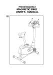
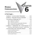
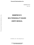
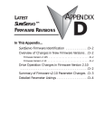
Speed control with MODBUS
THIS INFORMATION PROVIDED BY AUTOMATIONDIRECT.COM TECHNICAL SUPPORT IS
SUPPLIED "AS IS", WITHOUT ANY GUARANTEE OF ANY KIND. These documents are provided by
our technical support department to assist others. We do not guarantee that the data is suitable for
your particular application, nor do we assume any responsibility for them in your application.
PRODUCT FAMILY: SureServo
Number: AN-SERV-008
Subject: Speed control with MODBUS
Date issued: Jun-30-2009
Revision: First edition
This example shows how to use a Sureservo with MODBUS to control the speed
using a MODBUS RTU master PLC.
Here is shown a procedure on how to program a DirectLOGIC PLC, but the
concept is the same for other PLCs.
Rotary table
Servomotor
Gearbox ratio 8:1
In a given situation, we could create a displacement on a rotary table shown on the
adjacent figure to 1/4 of a revolution from the original position (or 2 revolutions in
the servo motor with a gearbox of 8:1 ratio) or any other angle, by programming
the parameters of P1-15 and P1-16 to 2 revolutions and 0 counts, P1-17 and P1-18
to, may be, 4 revolutions and 0 counts, and so on for up to 8 target preset positions.
What if we desire to change this desired position by an angle changed by an
operator? In a given application we may wish to place the rotary table in any angle
that we wish; of course we can program 8 positions with respect to absolute Home
position, or find a combination of incremental positions to move the table in certain
discrete positions.
What options do we have if we wish to define the revolutions and the pulses only
some moments before the movement? This is possible writing data to registers of
the Sureservo through the CN3 port of the drive, that allows the data transfer in a
transmission rate of up to 115.2 kbps (kilobit per second).
1st Ed.
6/09
Luis Miranda
1
Speed control with MODBUS
DirectLOGIC PLC’s can be master and use port 2 with up to 38.4 kBaud, namely
CPU’s D2-250-1, D2-260, DL05 and DL06 PLCs , or up to 115.2 kbps using the port
2 of D0-DCM module.
Any other system that could transmit commands as a master with MODBUS can
also make this exchange of information.
In this example we will show only the velocity mode control.
Speed control with Sureservo can be done in several ways:
- Using an analog input with a signal +/- 10 Volt in terminal V-REF.
- Using up to 3 preset values stored inside the servo drive and selecting then with
the combination of 2 digital inputs.
- Using an external pulse train.
- Using a master PLC with MODBUS protocol, to write the value of speed.
This is the purpose of this application note.
The speed “writing” to the servo is one of many possibilities; it has, of course, the
possibility to write the target positions, we can change other parameters such as the
acceleration and deceleration, speed, torque and speed and torque limits, etc.
We can also read the status, the current position, the current torque, the motor
speed as a number directly expressed in rpm, and not only through the single
analog signal.
Use of MODBUS with Sureservo
A characteristic of the Sureservo drive is the possibility of linking the registers of the
servo, as slave, to a PLC, as a master, using MODBUS RTU.
The technical note AN-SERV-004, available in the web site of Automation Direct, in
the area of Technical support>Application Notes shows a simple example on how
to implement a communication link through port 2.
DirectSOFT software allows the programming of instructions MRX and MWX in a
very simple way, when the PLC DL06 or the CPU D2-260 is used, but not every
command is done through MODBUS. The DL05 PLC and the CPU D2-250-1 have
the instructions RX and WX or NETRX and NETWX.
New firmware 2.105 on the servo allows to command the digital inputs through
MODBUS. Previous versions allowed the transfer of some of the parameters only,
but not digital inputs.
Sometimes it is convenient to do so, but there are certain inconveniences that we
will not describe in detail in this document, but, as example, the Home sensor
should be wired directly to the servo drive, to avoid delays on the detection of the
Home position. Other example is the wiring of overtravel limit switches, that are
safety switches and would be better to hardwire them.
2
Luis Miranda
Speed control with MODBUS
Introduction to communications with MODBUS RTU protocol
Before explaining the example, we will develop an introduction to serial
communications with Sureservo using MODBUS RTU protocol .
A communication protocol is a 'language’ used by devices in a network to
communicate with each another. All the devices in the network must use the same
communication protocol to be able to communicate among them.
The MODBUS RTU serial protocol is a standard protocol very common in the
industry, and it is used to communicate with an ample variety of industrial devices
that support this protocol. In this case, it is needed a Master device to command the
servo, which is acting as slave.
There are three standards of wiring that can be used with the Sureservo actuators:
RS-232C is a wiring standard point to point with a practical distance of wiring of 15
meters, or 50 feet, maximum. Only two devices can communicate in a RS-232C
network, only a master device and one slave device and the total cable length can
not exceed 50 feet. A cable Belden® 8102 or equivalent is recommended, for
networks RS-232C. A cable Belden 9729 also will work.
RS-422 is a standard of multiple nodes with a practical distance of wiring of 1000
meters, or 3280 feet, length overall maximum. This means that a master can
communicate with up to 247 slaves theoretically, but in practice about 10 slaves is
the maximum practical limit, and the total distance of all the network between all
the devices cannot exceed 1000 meters, or 3280 feet. Standard RS-422 does not
specify a topology of the network, but actually, a topology of multiple connections
in series with the master on one end is the only way to make the communication
reliable (daisy chain). The cable Belden® 8102 or equivalent is recommended for
networks RS-422. Use a termination resistor of equal value to the characteristic
impedance of the cable that is used (100 for Ohm Belden 8102) at both ends of the
network.
RS-485 is a standard of wiring of multiple nodes, with a practical distance of
maximum wiring of 4000 feet. Standard RS-485 does not specify a network
topology, but actually, a topology of multiple connections in series with the master
on one end (daisy chain) is the only way to make the communication reliable. The
cable Belden 9841or equivalent is recommended, for networks RS-485. Use a
termination resistance of equal value to the characteristic impedance of the cable
that is used (120 Ohm for Belden 9841) at both ends of the network.
The data transmission uses digital asynchronous serial data transmission. The
characters are sent codified in bits, one bit every time, in signal levels such as the
ones in RS-232C.
The detail of this transmission is outside the intention of this document and more
will not be explained here. The reader can look for information on this subject in
Internet or specialized books. From the point of view of the user, this is not
important and it is mentioned here only for better understanding of the basic
concepts.
1st Ed.
6/09
Luis Miranda
3
Speed control with MODBUS
It does not matter what wiring protocol is used, there are several communication
parameters that must be selected for each device before they can establish the
communication. These parameters include:
Transmission rate in kilobits/s (kbps) [Baud rate]
Flow control
Data bits
Echo Suppression
Parity
Timeouts
Stop bits
Delay times
Node address
Format
All these parameters may not be necessary, or not be available. The used parameters
depend on the device that is used, and if the device is a master or a slave.
NOTE: The point to remember is that when the same parameters are available in the
master and the slave (that is, baud rate, parity, stop bits, etc), the values of these must be
equal.
The serial transmission can be of the type half duplex or full duplex. A transmission
half duplex can transmit in both directions, but in a single direction every time. One
full duplex can transmit data in two-way traffic simultaneously.
For example, it is possible to be said that a walkie talkie is half duplex, because it
can only transmit the voice in a single direction. In contrast, a telephone is full
duplex, since both parties can talk simultaneously.
The servo drive only can be half duplex.
A serial network can be the one as shown one in the following figure: The network
is controlled by a master station, that typically is a PLC with capacity to execute
these orders, which commands the data interchange to each one of the slaves, in a
sequence one at a time.The slave responds to the orders of the master. The slave
cannot initiate communications.
Generates orders or instructions to transfer data; for example
read the data in the slave register whose address is 40002.
The servo drive, that is the slave in this case, has registers with parameters whose
content causes the servo to work the way that the designer of the control system
wishes it to work.These registers have location addresses you select, shown in the
chapter 6 of the servo drive user manual. For example, if you want to read if the
servo is with or without fault or want to know the type of fault in case there is an
alarm, you can read the register 40002, that corresponds to the P0-02 parameter.
4
Luis Miranda
Speed control with MODBUS
How can we control the servo through a network?
You can easily create a control system with a servo using a serial MODBUS network
following the six steps below:
1) Define the control concept.
2) Design the network according to your application; select the master who will
communicate with the slave or slaves.
3) Select the cables and communication parameters.
4) Create the program in the master PLC and set up the slave.
5) Run the start up of the network setting up the port and activate the program of the
master to initiate the communications.
6) Test that the actuator works as desired.
Let us see the control of a servo using a speed reference given by the control though
Modbus.
We will explain this with an example that uses speed set point and PLC port 2:
1) Control concept: In this example we will need to run a motor with a speed
reference with a value given in memory V2000, directly in rpm in binary format,
that can be written, by example, from a calculation on the PLC, or from a
tachogenerator, or read with an analog input module or from the determination
of speed from encoder. The acceleration and deceleration can be fixed,for now,
but also it can be written to the servo drive through MODBUS communication.
The speed reference will be written in the servo drive to the P1-09 parameter and
the servo will be enabled with one of the virtual inputs defined in P4-07 with help
of P3-08, as is explained on page 11 in this document. The values will be chosen
either 0 rpm or the value in P1-09.
2 Network design: One possibility is to link them with RS-422, as in the following
figure:
Configuration for RS-422
The SVC-MDCOM-CBL is a cable of 3 feet length and the ZL-CMA15L module only
measures about 2 inches; therefore this can be a physical configuration whose cable
distance between the drive and the PLC can have about 3 feet ONLY. If more
distance is needed, it can be of up to 1000 meters with an additional RS-422 cable
you can add in series.
1st Ed.
6/09
5
Speed control with MODBUS
3) Select the parameters: Set P3-00 parameter to the desired slave address. In this
case we will use the value 2, that is just to say servo drive slave 2.
Then set a value 3 in P3-01, that defines the transmission rate as 38.4 kBaud. This
value also must be set in the configuration of PLC port 2.
P3-02 defines the protocol and the configuration. In this case, we select 8 as
MODBUS RTU, 8 data bits, odd parity, 1 stop bit.
Finally, we set the P3-05 value with a value of 1 (RS-422).
This configuration is done with the keypad of the servo drive.
The communication parameters in DL06 PLC or D2260 CPU are configured
with DirectSOFT5 software
or by ladder code. This is
explained in the manual
D0-06USER-M or the D2USER-M, respectively and
we only show it here the
adopted values, in the
adjacent figure.
If you use another type of
master device, see how to
set these values in the
manual of the master
device. Any master that
follows the MODBUS RTU
specifications can be used.
Next, leave the other values
as factory default.
Then we must connect the PLC to the servo drive.
4) Creation of the program: In order to be able to read the data from the servo drive
and at the same time to verify that the connections are correct, I suggest to run
the program shown in the following diagram.
Set a value 10 in the P2-08 parameter with the keyboard to configure all the
values of the servo as default values. Errors ALE14, ALE15 and ALE13 will appear
on the display and this is normal.
Next, be sure that the value of the motor code is set in the P1-32 parameter.
When the servo is powered up, but not enabled and the axis of the motor turns
freely, the data that is contained in the parameters P0-00 to P0-08 can be read.
These parameters have memory addresses 40001 up to 40009, as shown in the
table on the following page and described in the user manual in chapter 6.
6
Luis Miranda
Speed control with MODBUS
This is the explanation of the operation:
SP116 is a bit in the PLC that turns ON when there is communication on port 2. It
is called "Busy" and indicates when the PLC is transmitting data through the
communication in port 2, and turns OFF when the data transmission is completed.
Therefore, on the first scan, instruction MRX is executed and reads 9 consecutive
registers from the servo. See more details in the PLC manual. Let us say that the PLC
scan takes 2 ms; when beginning the transmission the contact of bit SP116 closes and
makes the rung true to allow the transmission to be executed. When establishing the
transmission, SP116 turns ON; when the transaction completes, SP116 contact is
closed again and then another transaction begins and thus it follows continuously.
Typically the transmission takes more than the PLC scan time. In this case it is
approximately 18 ms.
The values in the selected range go to the memories of the PLC V3000 to V3010,
according to the following table:
Parameter
P0-00
P0-01
P0-02
P0-03
P0-04
P0-05
P0-06
P0-07
P0-08
Value
2105
14
0
1
1
0
0
0
0
MODBUS address
40001
40002
40003
40004
40005
40006
40007
40008
40009
PLC memory
V3000
V3001
V3002
V3003
V3004
V3005
V3006
V3007
V3010
Description
Software version
Fault code
Display code
Analog monitor
Status monitor 1
Status monitor 2
Status monitor 3
Status monitor 4
Status monitor 5
The fault ALE 14 and others in the servo drive display indicates that the overtravel
limit switch is activated, and this is true, since of P2-15 default (that corresponds to
the DI6 input function) it set as 22, P2-16 (that corresponds to the DI7 input
function) is set as 23 and P2-17 (that corresponds to the DI8 input function) is set
as 21.
To make these errors disappear we must set P2-15 to P2-17 to a value 0 to disable
the function of each input in DI6, DI7 and DI8. In order to clear the faults press the
“up and down arrow” keys on the keypad simultaneously cleaning any error can be
there, or it is also possible to power cycle the servo drive to get the same function.
Also it is necessary to place some function in the parameters P0-03 to P0-08 to be
able to visualize what it is desired to see in the PLC.
We will change the values in the parameters according to the following table:
1st Ed.
6/09
Luis Miranda
7
Speed control with MODBUS
Parameter
P0-00
P0-01
P0-02
P0-03
P0-04
P0-05
P0-06
P0-07
P0-08
Value
2105
14
0
1
1
0
6
11
13
MODBUS address
40001
40002
40003
40004
40005
40006
40007
40008
40009
PLC memory
V3000
V3001
V3002
V3003
V3004
V3005
V3006
V3007
V3010
Description
Software version
Fault code
Drive Status
Analog monitor
Current revolutions
Current counts
Current rpm
Current % torque
DC Bus voltage
The values in V3000 until V3007 are all signed decimal values.
When you have changed the parameter values, you can move the shaft of the
servomotor and it will be possible to observe that the V3005 memory shows the
same number that the display on the servo, and can be seen that the speed changes,
when the shaft of the motor moves. The DC voltage in P0-08 should be of the order
of 305 to 315 Volt DC, as it is in V3010, as decimal value. This allows us to check
that the communication has been established.
How can we measure the PLC scan time and how many
transactions are happening per second? With the
following method:
- The scan can be seen using menu PLC > Diagnostics
in DirectSOFT and then select "scan Time"; the
dialogue of the adjacent figure will appear:
- As we know, when a communication transaction
begins SP116 will turn ON, and then we can count how many times the SP116
contact closes in 1 second, for example with a simple counter. Remember that a
counter counts whenever there is a transition of the input from OFF to ON. See
the diagram below with the ladder code corresponding and the explanations in
each line.
C0 closes one scan every second
Every time C0 closes the current count is copied to V4000
Here the counter CT0 counts the closing of SP116
C0 resets the counter every one second
8
Luis Miranda
Speed control with MODBUS
You can read V4000 in Data View and can
see that the result is 55 or 56 counts every
second. Since there are 1000 milliseconds
in a second, 1000/55 ms is approximately
18 ms on each transaction. See the
adjacent figure.
This it is a good method to determine the
transmission speed.
When the comm link between the PLC and
the servo has been tested, we should code
in the PLC something to be able to give the
servo the value of speed setpoint.
Remember that we are still in the stage of creation of the program on the master
PLC. Also it is necessary to define how data is written to the servo drive.
We have said previously that we want to write the speed value in P1-09.
The following logic can be written for MRX and MWX to avoid execution at the
same time. For that we do an interlock between reading and writing. This is the
fastest update possible. A simple way to do this is the following:
At the beginning, the
closed contact SP116
and C1 allow the
reading with MRX, but
immediately will turn
ON C1 with the SET
instruction, and waits
for SP116 to be turned
OFF.
C1 will close but SP116
will be ON (busy);
when the reading
transaction
is
completed, the writing
begins with instruction
MWX; C1 is turned OFF
with
the
Reset
instruction.
Notice that only one transaction at a time is possible.The PLC will be reading or
writing in sequence.
Nevertheless, it is necessary to consider the following:
The servo drive has two types of memory, RAM and EEPROM. In RAM memory data
can be written at any time but the memory EEPROM can be written a limited
number if times, the order of 100,000 times. The fixed parameters are written
typically in EEPROM memory and with this memory it is not necessary to maintain
drive power. When powering the servo drive, these values will be still stored in the
memory.
1st Ed.
6/09
Luis Miranda
9
Speed control with MODBUS
In RAM memory this is not possible and the data only stays if the drive stays
powered. If we want to write continuously to the drive memory, we should set the
value of P2-30 parameter as 5; but this value is not retained in memory EEPROM.
Clearly it is not possible that the setting of this value be done by the operator of the
machine when the servo powers on. Therefore it is necessary to write a value 5 to
this memory when the drive powers ON or otherwise the servo will reach the limit
of writings and the device will not be functional anymore.
One of several ways is to use a comparison function reading the content of P2-30
parameter and on the basis of that value execute a writing of that parameter.
It can be created an interlock such that this function is not executed anymore when
P2-30 (MODBUS address 40543 [or 21E in hexadecimal format ] has a 5 in its
content.
Here it is advisable the use of the block transfer parameters P0-09 up to P0-16, that
are configurable parameters allowing to read or write data in consecutive servo
addresses, which is better than to read data in random addresses (not consecutive).
For that, we will configure P0-09 with the keyboard (By default with value 407) as
21E, that causes this parameter to be defined as P2-30.
Then we will increase the reading of 9 registers in MRX to 10, to have included P009.
For example:
Instruction MRX reads 10
consecutive registers up to P009. P0-09 is the value contained
in P2-30, that corresponds to
V3011. C1 turn ON with the coil
SET
V3011 content is compared with
5. If is not so, turn ON C2.
If C2 is ON and SP116 is OFF, it
is written the value in V4010
(That is 5, forced by the first line
not shown here) in P2-30,
through P0-09.
When the content of V3011 is 5,
C2 is turned OFF.
This is the writing instruction that
writes the value of V2000 in P109. Enabling this function turns
OFF C1, and now it is possible
to read the 10 data again.
This it is the interlock between
reading and writing
10
Luis Miranda
Speed control with MODBUS
Now we have the complete communication defined but we cannot command the
servo to be moved through MODBUS.
We need to be able to enable the servo, with a virtual digital input and to define
acceleration and deceleration, the operation mode and other constants that are
listed below (Other parameters are left by default):
- P1-01 Operation mode, that by default is 0, set as 4.
- P1-32 Selection of the stop mode, changed to 1 from value 0.
- P1-34 Acceleration time: Let us define 1000 ms.
- P1-35 Deceleration time:500 ms to arrive at 0.
- P1-55, left as 5000.
- P2-10, DI1, set as 101
- P2-11, DI2, set as 0
- P2-12, DI3, set as 114
- P2-13, DI4, set as 115
- P2-14 until P2-17 set as 0 (Disabled inputs)
The values of digital inputs are defined by the content in the P3-08 parameters and
the P4-07.
P3-08 is a parameter that allows control of digital inputs with MODBUS.
Each one of the parameter bits has a predefined function or defined with other
parameters.
If any one of the eight less significant bits is a 1, digital inputs DI1 until DI8 are used
with MODBUS. The 8 most significant bits have predefined functions.
Bit
order
1st Ed.
6/09
Digital
input
Code
0
DI1
101
1
DI2
0
2
DI3
3
DI4
4
DI5
5
6
Assigned
value
Description.
Servo Enable
1
Disabled
1
114
VCS0
1
115
VCS1
1
0
Disabled
0
DI6
0
Disabled
0
DI7
0
Disabled
0
7
DI8
121
External fault stop
0
8
DI9
08
Trigger - Predefined value
0
9
DI10
11
PCS0 - Predefined value
0
10
11
DI11
DI12
12
13
PCS1 - Predefined value
PCS2 - Predefined value
0
0
12
DI13
02
Alarm reset - Predefined value
0
13
DI14
27
Home search trigger- Predefined value
0
14
DI15
37
JOG Forward- Predefined value
0
15
DI16
38
JOG Reverse- Predefined value
0
Luis Miranda
11
Speed control with MODBUS
We will set each one of the bits according to the following table:
Bit
order
Digital
input
Code
Description
Assigned value PLC bit
0
1
2
3
4
5
6
7
8
9
DI1
DI2
DI3
DI4
DI5
DI6
DI7
DI8
DI9
DI10
101
0
114
115
0
0
0
21
08
11
Servo Enable
Disabled input
VCS0
VCS1
Disabled input
Disabled input
Disabled input
External fault stop
Trigger- Predefined value
PCS0 - Predefined value
1
1
1
1
0
0
0
0
0
0
10
11
12
13
14
15
DI11
DI12
DI13
DI14
DI15
DI16
12
13
02
27
37
38
PCS1- Predefined value
PCS2 - Predefined value
Alarm reset- Predefined value
Home search trigger- Predefined value
JOG Forward- Predefined value
JOG Reverse.- Predefined value
0
0
0
0
0
0
C100
C101
C102
In this case, we must place P3-08 as 000F. Enter this value with the keypad.
The concept of speed control will be so that, after enabling the servo drive output
with DI1, will be able to be select the speed in P1-09 or a speed of 0.
P4-07 is the parameter that contains the digital inputs on each one of the bits.
We will associate to P4-07 the following:
Therefore, P3-08 has the first 4 bits set to 1. The first least significant bit of P4-07
must be turned ON so that the servo works; third to select the speed P1-09, the
quarter to select the speed in P1-10 (that is zero, so far, but it can be any other speed
in the operation range of the servo).
Notice in the figure of the following page that we added line 1, to cause that C0 to
C10 always be OFF in the beginning of the program when powering up the PLC and
that the V4010 memory has value 5 to be able to pass this value to P2-30 at the right
moment.
What is a value of memory V to send the data of the digital inputs and the value
in P1-10? The answer is given by the following:
We can define the 3 consecutive parameters beginning in P0-10 and consecutive in
such way than they are the values of speed in P1-09 (P0-10), P1-10 (P0-12) and the
digital input word in P4-07 (P0-12). Therefore, it is necessary to change the code of
line 9 so that 3 consecutive registers could be written and the function will be 16
instead of 6.
We must write with the keypad the following:
P0-10 will be desired speed 1 with the value 109hex equivalent to P1-09.
P0-11 will be desired speed 2 with the value 10Ahex equivalent to P1-10.
P0-12 will be the word with the digital inputs with the value 407hex equivalent to
P4-07.
12
Luis Miranda
Speed control with MODBUS
Since we had defined that V2000 is the value of speed reference, it is logical that
we will have the V2001 values as the second speed, that is zero so far, and V2002
must be equal to what goes in P4-07.
This allows to write in those memories and the only thing that is missing is to relate
the bits of V2002 to C100, C101 and C192. See the ladder code in the next pages.
_FirstScan
SP0
LD
1
K5
OUT
V4010
C0
C10
RST
_1Second
SP4
C0
PD
2
C0
LD
3
CTA0
OUT
Transactions/s
Datos/segundo
V4000
SP116
CNT
4
CT0
K9990
C0
SP116
C1
C2
5
MRX
CPU/DCM Slot :
CPU
Port Number :
K2
Slave Address :
K2
Function Code :
03 - Read Holding Registers
Start Slave Memory Address :
K40001
Start Master Memory Address :
V3000
Number of Elements :
K10
Modbus Data type :
584/984 Mode
Exception Response Buffer :
V10000
C1
SET
IfSithe
content de
of V3011
V3011noisesnot
equal
and
C1active
is ON,
el contenido
igual
a 5 y to
C15está
ON,
C2 turn ON C2
C1
V3011
6
K5
C2
SET
(Continues on next page)
1st Ed.
6/09
Luis Miranda
13
Speed control with MODBUS
Lines 2 to 4 are used for the determination of data transmission speed, as explained
on a previous page.Rungs 5, 6 and 7 were already explained.
Rung 8 turns OFF the bit C2 when the value in P2-30 is set to 5.
Rung 9 executes the writing of 3 words to the P0-10 to P0-12 parameters.
Rungs 10, 11 and 12 change the bits of the V2002 memory to cause that P4-07 gives
the digital inputs servo enable, and select one of the speeds.
IfSIC2
is ON, copy the value of 5 into P2-30 to allow only RAM writing
C2 está activado, copie el valor 5 en P2-30 para poder escribir solamente en RAM
C2
SP116
MWX
CPU
CPU/DCM Slot :
Port Number :
K2
Slave Address :
K2
Function Code :
06 - Preset Single Register
Start Slave Memory Address :
K40010
Start Master Memory Address :
V4010
Number of Elements :
n/a
584/984 Mode
Modbus Data type :
Exception Response Buffer :
V10040
7
If
the
content
V3011
is 5,a reset
C2 C2
Si el
contenido
deof
V3011
es igual
5 , desactive
V3011
K5
C2
8
RST
SP116
9
C1
C2
MWX
CPU/DCM Slot :
CPU
Port Number :
K2
Slave Address :
K2
Function Code :
16 - Preset Multiple Registers
Start Slave Memory Address :
K40011
Start Master Memory Address :
V2000
Number of Elements :
K3
Modbus Data type :
584/984 Mode
Exception Response Buffer :
V10020
C1
RST
Servo enable
C100
10
VCS0
C101
11
VCS1
C102
14
B2002.0
OUT
B2002.2
OUT
12
B2002.3
OUT
13
END
Luis Miranda
Speed control with MODBUS
The program is complete for this example.
Notice that the instruction MWX uses the data in 3 memories:
- V2000, that goes into P1-09, the speed reference, to be changed in some way on
the PLC, for example, with an operator interface, or by a calculation inside the
PLC.
- V2001, other possible speed that will go into P1-10.
- V2002, that is the word to be sent to P4-07 to define when the inputs are active.
In summary, MODBUS RTU can transfer data in an operation of reading or writing
one at the time, the P2-30 parameter in the servo must be set as 5 and we can create
virtual digital inputs using the parameters P3-08 and P4-07.
Naturally, it is necessary to emphasize the use of the P0-09 parameters to P0-16, for
block transfer.
Take into account that initially we had 55 readings per second; when a writing
instruction is added, the writing counts must also be considered and therefore, the
number of readings decreases. Evidently it is possible to create counters for readings
and writings.Another possibility is to only write when necessary.
The reader can consider to do this if it is important in the process.
5)Operate the network, by activating the master program to initiate the
communications.
Use Data View in DirectSOFT for the next actions:
5.1 - Set a value of rpm in V2000, for example, 300 rpm.
5.2 - Turn ON C100 to enable the servo. The motor will be powered and you will
hear the typical noise of motor windings excited. The shaft should be locked
in position.
5.3 - Turn ON C101 and the servo will rotate at the speed defined in V2000. You
can change the speed at any time .
5.4 - The servo can be stopped by turning off the bit C101 or you can disable the
servo.
1st Ed.
6/09
Luis Miranda
15
Speed control with MODBUS
16
Luis Miranda