1
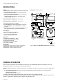
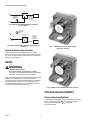
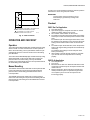
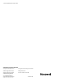
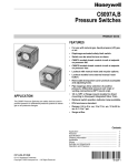
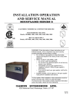
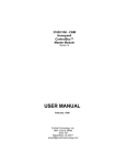
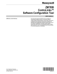
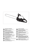
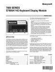
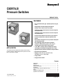
C6097A,B
Pressure Switches
PRODUCT DATA
FEATURES
• For use with natural gas, liquid propane (LP) gas,
or air.
• Diaphragm-actuated safety-limit switch.
• Switch can be wired to turn on alarm.
• C6097A models break control circuit at setpoint
on pressure fall.
• C6097B models break control circuit at setpoint
on pressure rise.
• Lockout with manual reset and recycle options.
• Lockout models have external manual reset
button.
• Removable transparent cover protects scaleplate
and adjusting knob.
• Pipe tappings allow selection of positive
pressure, differential pressure (air only) or
venting connections (NPT mount only).
APPLICATION
The C6097 Pressure Switches are safety devices used in
positive-pressure or differential-pressure systems to sense
gas or air pressure changes.
• 1/4 in. NPT or flange mount models for direct
mounting to Honeywell Integrated Valve Train.
• Optional switch position indicator lamp available.
• IP54 enclosure standard.
• Ranges: 0.4 to 5 in. wc, 3 to 21 in. wc,
12 to 60 in. wc or 1.5 to 7 psi.
• Surge orifice.
• Integral Vent Limiter.
Contents
Application ........................................................................
Features ...........................................................................
Specifications ...................................................................
Ordering Information ........................................................
Installation ........................................................................
Optional Switch Position Indication Lamp ........................
Wiring ...............................................................................
Settings and Adjustments .................................................
Operation and Checkout ..................................................
1
1
2
2
4
4
6
6
7
CP-UM-5109E
5th Edition: Issued in Jan. 2008
65-0237-05
C6097A,B PRESSURE SWITCHES
SPECIFICATIONS
Models:
C6097A Pressure Switch: Breaks a circuit when pressure falls
to scale setting. See Table 1.
C6097B Pressure Switch: Breaks a circuit when pressure
rises to scale setting. See Table 1.
Table 2 shows switch ratings and Table 3 shows alternate
electrical ratings when used with Honeywell Flame
Safeguard Programmers.
Dimensions: See Fig. 1 and 2.
2-21/32 (68)
2-21/32 (68)
15/32 (12)
1-3/32 (28)
27/32
(22)
1-17/32
HOLE
(90)
Minimum Ambient Temperature: -40°F (-40°C).
3-3/16
(81)
Maximum Ambient Temperature: 140°F (60°C).
2-1/4
(57)
Connections (Depending on Model):
1/4-18 NPT tapping for main or high-pressure connection.
1/8-27 NPT tapping for vent or low-pressure connection
(air only).
Flange mount for connection to Honeywell Integrated Valve
Train (internal vent only, no external connections).
13/32
(11)
31/32
(25)
2-23/32 (69)
2-23/32 (69)
1-3/4 (45)
INDICATOR
HOUSING
2-13/32
(61)
Scale Range:
0.4 to 5 in. wc (0.10 kPa to 1.25 kPa).
3 to 21 in. wc (0.75 to 5.23 kPa).
12 to 60 in. wc (3.0 kPa to 15 kPa).
1.5 to 7 psi (10.3 kPa to 48 kPa).
25/32
(21)
Approvals:
Underwriters Laboratories Inc. listed.
Canadian Standards Association listed.
Factory Mutual: Approved.
Industrial Risk Insurers: Acceptable.
CSD-1 AFB: Acceptable.
DIFFERENTIAL
CONNECTION
1/8 NPT
GAS CONNECTION
1/4 NPT WITH DUST SEAL
TERMINAL DIAGRAM
1 2
3
NO
COM
NC
Accessories:
32003041-001 C6097 Cover for manual reset models.
32003040-001 C6097 Cover for recycle models.
32003039-001 Position Indication Lamp Kit.
P
M17125
Fig. 1. C6097 1/4 in. NPT Mount dimensions in in. (mm).
ORDERING INFORMATION
When purchasing replacement and modernization products from your TRADELINE® wholesaler or distributor, refer to the
TRADELINE® Catalog or price sheets for complete ordering number.
If you have additional questions, need further information, or would like to comment on our products or services, please write or
phone:
1. Your local Honeywell Automation and Control Products Sales Office (check white pages of your phone directory).
2. Honeywell Customer Care
1885 Douglas Drive North
Minneapolis, Minnesota 55422-4386
In Canada—Honeywell Limited/Honeywell Limitée, 35 Dynamic Drive, Toronto, Ontario M1V 4Z9.
International Sales and Service Offices in all principal cities of the world. Manufacturing in Australia, Canada, Finland, France,
Germany, Japan, Mexico, Netherlands, Spain, Taiwan, United Kingdom, U.S.A.
65-0237—05
2
C6097A,B PRESSURE SWITCHES
Table 1. Pressure Switch Model Selection.
Manual Reset
Differential
Model
Operating
Pressure
Range
Maximum
at
Minimum
Setpoint
Maximum
at
Maximum
Setpoint
Non-Manual Reset
Differential
Nominal
Maximum
Differential
Type
Maximum
Rated
Pressure
(continuous)
(psi)
Manual
Reset
Additive
2.9
No
Air/Gas
Mediaa
Switch
Action at
Setpoint
Comments
0.4 to 5 in. —
wc
—
0.16 in.
wc
0.24 in. wc
C6097A1012
3 to 21 in. 2.4 in. wc
wc
4.2 in. wc
—
—
5.0
Yes
Air/Gas
C6097A1020
3 to 21 in. 2.4 in. wc
wc
4.2 in. wc
—
—
5.0
Yes
Air/Gas
Flange Mount
C6097A1038
12 to 60
in. wc
10 in. wc
12 in. wc
—
—
5.0
Yes
Air/Gas
1/4 in. NPT
Mount
C6097A1046
12 to 60
in. wc
10 in. wc
12 in. wc
—
—
5.0
Yes
Air/Gas
Flange Mount
C6097A1053
3 to 21 in. —
wc
0.24 in.
wc
0.48 in. wc
5.0
No
Air/Gas
1/4 in. NPT
Mount
C6097A1061
3 to 21 in. —
wc
—
0.24 in.
wc
0.48 in. wc
5.0
No
Air/Gas
Flange Mount
C6097A1079
12 to 60
in. wc
—
—
1.1 in. wc 2.4 in. wc
5.0
No
Air/Gas
1/4 in. NPT
Mount
C6097A1087
12 to 60
in. wc
—
—
1.1 in. wc 2.4 in. wc
5.0
No
Air/Gas
Flange Mount
C6097A1095
0.4 to 5 in. 0.6 in. wc
wc
1.0 in. wc
—
—
2.9
Yes
Air/Gas
1/4 in. NPT
Mount
C6097A1103
1.5 to 7
psi
1.1 psi
1.4 psi
—
—
9.3
Yes
Air/Gas
Flange Mount
C6097A1111
1.5 to 7
psi
1.1 psi
1.4 psi
—
—
9.3
Yes
Air/Gas
14 in. NPT Mount
C6097A1129
1.5 to 7
psi
—
—
0.1 psi
0.3
9.3
No
Air/Gas
Flange Mount
C6097A1137
1.5 to 7
psi
—
—
0.1 psi
0.3
9.3
No
Air/Gas
1/4 in. NPT
Mount
C6097A1210
0.4 to 5 in. —
wc
—
0.16 in.
wc
0.24 in. wc
2.9
No
Air/Gas
Flange Mount
C6097A1228
0.4 to 5 in. —
wc
—
—
—
2.9
Yes
Air/Gas
Flange Mount
C6097B1002
12 to 60
in. wc
10 in. wc
12 in. wc
—
—
5.0
Yes
Air/Gas
C6097B1010
12 to 60
in. wc
10 in. wc
12 in. wc
—
—
5.0
Yes
Air/Gas
C6097B1028
3 to 21 in. 2.4 in. wc
wc
4.2 in. wc
—
—
5.0
Yes
Air/Gas
1/4 in. NPT
Mount
C6097B1036
3 to 21 in. 2.4 in. wc
wc
4.2 in. wc
—
—
5.0
Yes
Air/Gas
Flange Mount
C6097B1044
1.5 to 7
psi
1.1 psi
1.4 psi
—
—
9.3
Yes
Air/Gas
Flange Mount
C6097B1051
1.5 to 7
psi
1.1 psi
1.4 psi
—
—
9.3
Yes
Air/Gas
1/4 in. NPT
Mount
C6097B1069
3 to 21 in. —
wc
—
0.24 in.
wc
0.48 in. wc
5.0
No
Air/Gas
Flange Mount
C6097B1077
12 to 60
in. wc
—
—
1.1 in. wc 2.4 in. wc
5.0
No
Air/Gas
Flange Mount
C6097B1085
12 to 60
in. wc
—
—
1.1 in. wc 2.4 in. wc
5.0
No
Air/Gas
1/4 in. NPT
Mount
C6097B1093
1.5 to 7
psi
—
—
0.1 psi
0.3 psi
9.3
No
Air/Gas
Flange Mount
C6097B1101
1.5 to 7
psi
—
—
0.1 psi
0.3 psi
9.3
No
Air/Gas
1/4 in. NPT
Mount
C6097B1119
3 to 21 in. —
wc
—
0.24 in.
wc
0.48 in. wc
5.0
No
Air/Gas
1/4 in. NPT
Mount
a
Subtractive
Breaks N.O.
to C.
connection
on pressure
fall.
1/4 in. NPT
Mount
C6097A1004
Breaks N.C.
to C.
connection
on pressure
rise.
1/4 in. NPT
Mount
1/4 in. NPT
Mount
Flange Mount
Acceptable media: Natural gas, liquid propane (LP) gas, and air.
3
65-0237—05
C6097A,B PRESSURE SWITCHES
When Installing this Product...
Table 2. Switch Ratings (Amperes).
1.
120/240 Vac, 50/60 Hz
Inductive
Full Load
3.0
Locked Rotor
18.0
Resistive
2.
5.0
3.
Table 3. Alternate Electrical Ratings when used with
Honeywell Flame Safeguard Programmers.
Device
4.
Rating
Ignition Transformer
540 VA
Pilot Valve
50 VA
Main Valve
400 VA with 2-1/2 times inrush.
27/32 (22) HOLE
5/8 (16)
Electrical Shock Hazard.
Can cause serious personal injury or death.
Disconnect power supply before beginning installation.
More than one disconnection can be involved.
Mounting
NOTE: On flange models, remove the label holding the
O-ring in place and make sure O-ring seal is in place
before mounting the pressure switch on the valve.
1-1/4
(32)
2-23/32 (69)
WARNING
2-21/32 (68)
2-1/4
(57)
2-23/32 (69)
The C6097 models allow NPT or flange (directly to valve)
mounting. The NPT models have a hexagonal fitting with a
1/4 in. NPT tapping, which is the high pressure connection, in
differential applications. The bleed fitting is 1/8 in. NPT tapped.
In differential pressure control applications using air only,
connect the lower pressure to the bleed fitting. See Fig. 1.
1/32
(1)
INDICATOR
PRESSURE INLET
2
(52)
TERMINAL DIAGRAM
1 2
3
Read these instructions carefully. Failure to follow
them can damage the product or cause a hazardous
condition.
Check the ratings given in the instructions and on the
product to make sure that the product is suitable for your
application.
Installer must be a trained, experienced service
technician.
After installation is completed, check out product
operation as provided in these instructions.
Both the flange mount and NPT mount models are supplied
with an Integral Vent Limiter. External vent line is not required.
If necessary, this 1/8-in. atmospheric vent fitting can be used
for the vent line connection.
C6097 models with flange mount can be fitted directly to
Honeywell Integrated Valve Train (model specific). See Fig. 2
and Table 1. The flange mount models vent internally, with no
external tap.
2 (52)
NO
COM
NC
P
Mount the C6097A,B in any position.
M17124
Leak Check
Fig. 2. C6097 Flange Mount dimensions in in. (mm).
After installation, perform a leak check on the pressure switch:
1. Turn on main gas. Make sure gas has reached the
pressure switch (e.g., high gas pressure switch)
2. Check installation for gas leaks using a gas leak detector
or a soap solution.
INSTALLATION
WARNING
Explosion or Fire Hazard.
Can cause severe personal injury, death or
property damage.
Observe all safety requirements each time a control is
installed on a burner.
OPTIONAL SWITCH POSITION
INDICATION LAMP
The 32003039-001 Switch Position Indicator Lamp Kit consists
of a plastic bag containing the following parts (see Fig. 1):
1.
2.
3.
4.
65-0237—05
4
Lamp and wires.
Terminal plate.
Captive screw and nut.
Screw.
C6097A,B PRESSURE SWITCHES
3-11/32 (85)
1-19/32 (40)
4-1/8 (105)
LAMP AND WIRES
1/2
(13)
1/4 (6)
SCREW
TERMINAL
PLATE
CAPTIVE SCREW
AND NUT
M16523
C6097
COVER
Fig. 3. 32003039-001 Position Indication Lamp Kit.
Installation
C6097
BODY
WARNING
SLIDE TWO LAMP WIRES
THROUGH SLOT
Explosion or Fire Hazard.
Can cause severe personal injury, death or
property damage.
Observe all safety requirements each time a control is
installed on a burner.
WARNING
Electrical Shock Hazard.
Can cause serious personal injury or death.
Disconnect power supply before beginning installation.
More than one disconnection can be involved.
CONNECTIONS FOR
LAMP LEADWIRES
Installing the Position Indication Lamp Kit
(See Fig. 4)
1.
2.
3.
4.
5.
6.
Remove the cover from the C6097 by removing the
screws in the upper left and lower right quadrants of the
cover.
Place the lamp in the slot to the right of the dial, in the
upper right-hand corner of the C6097, with the base
down. Run the two lamp wires through the slit in the
upper left corner of the lamp slot.
Place the nut in the hexagonal depression in the lower
left-hand corner of the C6097.
Place the terminal plate over the nut and fasten the
terminal plate to the C6097 with the screw through the
bottom hole in the terminal plate.
Place the captive screw through the terminal lug on the
shorter wire and fasten the wire to the terminal plate with
the captive screw secured by the nut under the terminal
plate.
Using Fig. 5 or 6 for reference, fasten the terminal lug on
the longer lamp wire to either the normally open (NO) or
normally closed (NC) terminal of the C6097.
5
LAMP
1
NC
NO
L2
1
CONNECT L1 (HOT) LEAD TO THE NO OR NC TERMINAL
BASED ON MODEL AND DESIRED LAMP FUNCTION.
M16522
Fig. 4. Installing the Position Indicator Lamp Kit.
65-0237—05
C6097A,B PRESSURE SWITCHES
C6097A
C
L1
POSITION
INDICATION
LAMP
NO
FLAME
SAFEGUARD
CONTROL
(RM78XX)
NC
M16524
L2
Fig. 5. Wiring the Position Indicator Lamp Kit
in the C6097A.
POSITION
INDICATION
LAMP
L2
C6097B
C
L1
M16525
NO
FLAME
SAFEGUARD
CONTROL
(RM78XX)
NC
Fig. 6. Wiring the Position Indicator Lamp Kit in the
C6097B.
Fig. 7. C6097 (manual reset switch model)
with cover removed.
Position Indicator Lamp Operation
The Position Indicator Lamp will light when the C6097
Pressure Switch opens and provides power to the lamp (see
Fig. 5or 6). An option alarm circuit can also be connected as
shown in the same figures.
WIRING
WARNING
Electrical Shock Hazard.
Can cause serious personal injury or death.
Disconnect power supply before beginning installation.
More than one disconnection can be involved.
Make sure that all wiring agrees with all applicable local codes,
ordinances and regulations. An opening is provided to
accommodate rigid conduit or armored cable for line voltage
operation (see Fig. 3 and 4). Do not overload the switch
contacts (see Switch Ratings in the Specifications section).
The switching schematic is shown in Fig. 5.
Fig. 8. C6097 (recycle model) with cover removed.
SETTINGS AND ADJUSTMENTS
Pressure Setpoint Adjustment
To adjust the pressure setting, turn the setpoint adjustment dial
(Fig. 3, 4 and 5) clockwise
to increase the pressure
setting and counterclockwise
to decrease
the pressure setting.
65-0237—05
6
C6097A,B PRESSURE SWITCHES
To reset, once normal operating pressure is restored, push the
reset button in as far as it goes, then release.
NO
IMPORTANT
Lockout models cannot be made to recycle
automatically by permanently holding in the
reset lever.
2
NC
Checkout
1
C
C6097 Gas Fuel Application
1
C6097A BREAKS C-NO, MAKES C-NC ON PRESSURE
FALL. MANUAL RESET MODELS LOCK OUT.
2
C6097B BREAKS C-NC, MAKES C-NO ON
PRESSURE RISE AND LOCKS OUT.
1.
2.
M17123
3.
4.
Fig. 9. C6097 schematic.
OPERATION AND CHECKOUT
Operation
5.
The manual reset C6097A diaphragm actuates the snap-acting
switch to break a control circuit and lock out when pressure
falls to the scale setting. The recycle C6097A models recycle
automatically when the control circuit returns to scale setting
plus differential.
6.
The manual reset C6097B diaphragm actuates the snap-acting
switch that breaks a control circuit and locks out when the
pressure rises to the scale setting. The recycle C6097B
models recycle automatically when the control pressure falls to
the scale setting minus differential.
Manual Resetting
The C6097A manual reset models lock out when pressure falls
to the scale setting and require manual resetting after the
pressure rises to scale setting plus differential to resume
normal operation.
Set cutoff pressure.
Open main supply line. Depress reset lever on lockout
models until switch makes control circuit.
Set controller and limit switch to call for heat.
For C6097A: Close the manual gas shutoff valve. C6097
should open control circuit when pressure reaches cutoff
point.
For C6097B: Open the manual gas shutoff valve, wait a
few minutes for the pressure to rise; then lower the scale
setting until the switch breaks control circuit and locks
out.
For C6097A: Open the shutoff valve, return the pressure
switch to its original setting and press the reset button (if
necessary).
For C6097B: raise setting to normal and press reset
button (if necessary).
Allow system to operate through at least one complete
cycle to make sure all components are functioning
properly.
C6097A Air Application
1.
2.
3.
4.
Set cutoff pressure.
Turn on fan.
Block fan inlet or filter area. Switch should break control
circuit when pressure drops to cutoff point. Manual reset
models lock out.
Remove obstruction. Press reset lever (manual reset
models) and allow system to operate through at least
one complete cycle to be sure all components are
functioning properly.
The C6097B manual reset models lock out when pressure
rises to the scale setting and require manual resetting after the
pressure falls to scale setting minus the differential to resume
normal operation.
7
65-0237—05
C6097A,B PRESSURE SWITCHES
Automation and Control Solutions
Honeywell International Inc.
Honeywell Limited-Honeywell Limitée
1985 Douglas Drive North
35 Dynamic Drive
Golden Valley, MN 55422
Toronto, Ontario M1V 4Z9
customer.honeywell.com
® U.S. Registered Trademark
© 2007 Honeywell International Inc.
65-0237—05 M.S. Rev. 09-07
Printed in Japan