1
Intepro Systems
ML1800 Series
Multiple Channel Programmable DC Electronic Load
User Manual
©All rights reserved Intepro Systems
Version V1.00
2013
Introduction
Dear User,
Thank you very much for choosing the Intepro Systems ML1800 series multiple channel
programmable DC electronic load. This manual is covers the use of the ML1800 series mainframe
and load modules including the installation, operation and specifications of the loads.
Please read the user manual carefully, especially the notes on safety, to insure that you can use the
load safely and correctly.
Please keep the manual, so that you can look up information as needed.
Announcement
All information in this manual is copyrighted by Intepro Systems. Information included in this manual
should be only for user’s reference and is subject to change without notice. Intepro is not responsible
for any damage, mistakes or losses caused by acting outside the guidance of this manual.
For latest news on the product, updates to the manual, please visit Intepro System’s website at
www.inteproate.com.
Certification
Intepro Systems certifies that ML1800 series electronic load meets its published specifications. It
also certifies that it adheres to it quality standards in its use of raw materials used and the
manufacturing design to ensure the highest quality product.
Warranty
This hardware product is warranted against faults caused under the normal use and maintenance
for a period of two years. Customer shall prepay shipping charges including duty and tax if required
for products returned to our repair facility. Intepro will pay for return of products to customer.
Limitation of Warranty
The warranty is only limited to the mainframe (excluding protective tube).
Any misuse, absentee
control, unauthorized modification, operation outside of the environmental specifications for the
products and damage from a major force is not covered and Intepro will not repair for free. Yearly
calibration is also not covered.
All repairs will offer an evaluation report before repair.
I
Only the warranty above is offered,no any other express or implied warranty is offered. Intepro
Systems is not responsible for any special, occasional or indirect damage.
Safety Summary
The following general safety precautions must be observed during all phases of operation and repair,
otherwise, the protection function of the product will be compromised .Intepro will not take any
responsibility for any consequences caused by the non-observation of safety notes.
Safety Instruction
Three-core cable is required for AC input of the load, and must be connected to ground;
otherwise potential hazardous events can occur that could result in personal injury.
Operating personnel must not remove the covers. Only trained and qualified personnel are
allowed to do service or calibration or the warranty will be voided.
Always ensure that AC input power is de-energized prior to connection or disconnecting any
cable.
Make sure the protection tube is assembled correctly before turning on the load.
Do not operate in an explosive and flammable atmosphere.
Do not assemble or replace any components alone or modify without authorization.
To avoid fire or permanent damage, please make sure the input voltage is no more than 50%
higher than the rated value.
Safety Symbols
Interpretation of international symbols used on the chassis and user manual is as the chart below:
II
Content
Introduction............................................................................................................................ I
Announcement....................................................................................................................... I
Certification....................................................................................................................... I
Warranty............................................................................................................................ I
Limitation of Warranty ..................................................................................................... I
Safety Summary..................................................................................................................... II
Safety Instruction ............................................................................................................ II
Safety Symbols ............................................................................................................... II
Content......................................................................................................................... III
1 Overview .................................................................................................................... 1
1.1 Introduction..................................................................................................................... 1
1.2 Main Features.................................................................................................................. 1
1.3 Chassis ............................................................................................................................. 2
1.4 Panel Introduction........................................................................................................... 3
1.4.1 Front Panel Introduction ...................................................................................... 3
1.4.2 Rear Panel Introduction ....................................................................................... 3
1.5 Module Introduction ....................................................................................................... 4
2 Installation ................................................................................................................. 5
2.1 Inspection ........................................................................................................................ 5
2.2 Cleaning ........................................................................................................................... 6
2.3 Installation....................................................................................................................... 6
2.3.1 Module Installation................................................................................................ 6
2.3.2 Channel Number................................................................................................... 7
2.3.3 Mainframe Installation .......................................................................................... 8
2.3.4 Input Connection................................................................................................... 8
2.4 AC Input Requirements ................................................................................................... 9
2.5 Power-on Self-test........................................................................................................... 9
2.6 Connections................................................................................................................... 10
2.6.1 Input Connection................................................................................................. 10
2.6.2 Sampling Connection ......................................................................................... 11
2.6.3 Parallel Connection ............................................................................................ 12
3 Functions and Features ......................................................................................... 13
3.1 Control Mode ................................................................................................................ 13
3.1.1 Local Control Mode ............................................................................................ 13
3.1.2 Remote Control Mode ........................................................................................ 13
III
3.2 Test Functions................................................................................................................ 14
3.2.1 CC Mode .............................................................................................................. 14
3.2.2 Constant Voltage Mode (CV) ............................................................................ 15
3.2.3 Constant Resistance Mode (CR)...................................................................... 16
3.2.4 Constant Power Mode (CP) .............................................................................. 16
3.2.5 LED Mode ............................................................................................................ 17
3.3 Apply Function............................................................................................................... 17
3.3.1 Constant Current Soft Starting Mode (CC Rise)............................................ 17
3.3.2 Constant Voltage Soft Starting Mode(CV Rise)........................................ 18
3.3.3 CC To CV............................................................................................................. 18
3.3.4 Constant Resistance to Constant Voltage Mode (CR To CV) ..................... 19
3.4 Programming Function.................................................................................................. 19
3.5 OCP Function ................................................................................................................. 20
3.6 Load Synchronization .................................................................................................... 20
3.7 Battery Charge Test Function ........................................................................................ 20
3.8 Input Control ................................................................................................................. 21
3.8.1 Turn on/off the load ............................................................................................ 21
3.8.2 Short Circuit ......................................................................................................... 21
3.8.3 Loading/Unloading Voltage ............................................................................... 21
3.9 Protection Features ....................................................................................................... 22
3.10 Slew Rate and Minimum Transition Time ................................................................... 23
3.11 Remote Sampling ........................................................................................................ 24
3.12 System Language......................................................................................................... 24
3.13 Fast Recall.................................................................................................................... 24
3.14 Turn-On Keypad Lock .................................................................................................. 25
3.15 Restore Factory Settings.............................................................................................. 25
4 Operation ................................................................................................................. 26
4.1 Keypad ........................................................................................................................... 26
4.1.1 Numeric Keypad ................................................................................................. 26
4.1.2 Function Keys...................................................................................................... 27
4.2 Channel Selection .......................................................................................................... 27
4.3 Setting up Operation Mode........................................................................................... 28
4.3.1 Constant Current Operation (CC) .................................................................... 28
4.3.2 Constant Voltage Operation (CV) .................................................................... 29
4.3.3 Constant Resistance Operation (CR) .............................................................. 30
4.3.4 Constant Power Operation (CP)....................................................................... 31
4.3.5 LED Operation..................................................................................................... 32
4.4 Setting Application Settings........................................................................................... 33
IV
4.4.1 Constant Current Soft Start Operation (CC Rise).......................................... 33
4.4.2 Constant Voltage Soft Start Operation (CV Rise).......................................... 34
4.4.3 Constant Current to Constant Voltage Operation (CC To CV) .................... 35
4.4.4 Constant Resistance to Constant Voltage Operation (CR To CV).............. 37
4.5 Setting OCP.................................................................................................................... 38
4.6 Programming ................................................................................................................. 39
4.6.1 Program Edit........................................................................................................ 40
4.6.2 Program Operation ............................................................................................. 43
4.7 Specification Examination ............................................................................................. 44
4.8 System Settings ............................................................................................................. 45
4.9 File Recall....................................................................................................................... 51
4.9.1 Recall Mode File ................................................................................................. 51
4.9.2 Recall OCP File................................................................................................... 51
4.9.3 Fast Recall ........................................................................................................... 52
4.10 Save File....................................................................................................................... 52
4.10.1 Save Mode File ................................................................................................. 52
4.10.2 Save Program File............................................................................................ 52
4.10.3 Save OCP File .................................................................................................. 52
4.11 External Port................................................................................................................ 53
5 Remote Control ....................................................................................................... 57
5.1 GPIB interface................................................................................................................ 57
5.1.1 GPIB System Configuration .............................................................................. 57
5.1.2 GPIB Address...................................................................................................... 58
5.2 RS232 Serial Port ........................................................................................................... 58
5.2.1 Set Baud rate....................................................................................................... 59
5.2.2 Set Parity Check System................................................................................... 59
5.3 Remote Control Mode................................................................................................... 59
6 Programming Commands Overview .................................................................... 60
6.1 Introduction to Programming Commands .................................................................... 60
6.2 Command Definition ..................................................................................................... 60
6.3 Data Format................................................................................................................... 61
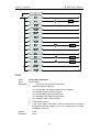
6.3.1 Digital Data Format............................................................................................. 62
6.3.2 Character Data Format ...................................................................................... 63
6.4 Separator and Terminator............................................................................................. 63
6.5 Command Terminator ................................................................................................... 64
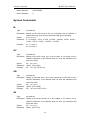
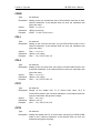
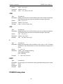
7 Command Details ................................................................................................... 64
7.1 Public Commands .......................................................................................................... 64
7.2 Specified Instructions .................................................................................................... 69
V
ABORT Subsystem ...................................................................................................... 69
CHANNEL Subsystem ................................................................................................. 69
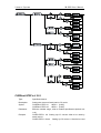
CONFIGURE Subsystem ............................................................................................ 71
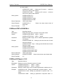
CURRENT Subsystem................................................................................................. 76
FETCH Subsystem....................................................................................................... 80
LOAD Subsystem ......................................................................................................... 82
MEASURE Subsystem ................................................................................................ 84
MODE Subsystem ........................................................................................................ 87
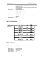
PROGRAM Subsystem ............................................................................................... 88
RESISTANCE Subsystem........................................................................................... 93
RUN Subsystem ........................................................................................................... 95
SPECIFICATION Subsystem...................................................................................... 95
STATUS Subsystem .................................................................................................... 99
VOLTAGE Subsystem ............................................................................................... 103
System Commands .................................................................................................... 105
POWER Subsystem ................................................................................................... 109
LED Subsystem .......................................................................................................... 111
OCP Subsystem ......................................................................................................... 112
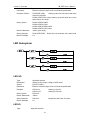
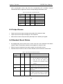
8 Status System ....................................................................................................... 117
8.1 Introduction................................................................................................................. 117
8.2 Channel Register Group............................................................................................... 117
8.2.1 Channel Status.................................................................................................. 118
8.2.2 Channel Summary............................................................................................ 119
8.2.3 Questionable Status ......................................................................................... 119
8.3 Output Queue.............................................................................................................. 120
8.4 Standard Event Status ................................................................................................. 120
8.5 Status Byte Register..................................................................................................... 121
8.6 Service Request Enable Register ................................................................................. 121
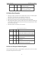
9 Practical Example ................................................................................................. 122
9.1 Introduction................................................................................................................. 125
9.2 Error Message Check ................................................................................................... 125
Specification............................................................................................................. 126
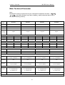
Supplementary Characteristic ........................................................................................... 126
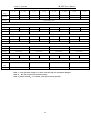
Main Technical Parameter ................................................................................................ 127
VI
Intepro Systems
ML1800 User Manual
1 Overview
This manual mainly includes the specification, installation and use instruction etc of
ML1800 series multiple channel electronic load.
1.1 Introduction
ML1800 series is the newly developed high end multiple programmable DC electronic
loads. This series load offers powerful test functions and friend user interface. The
ML1800 series loads can be applied to the test for DC power supply, battery, charger
and other related devices, which can offer many solutions for your design and testing.
This series product include ML1800 chassis, 4 models of module such as 66103A
(300W), 66105A (300W), 66106A (600W), 66108A (600W). The load chassis is
designed with open bays to easily receive a maximum of 6 load modules, which is
very applicable for configuring power supply test platform, and is cost efficient. The
ML1800 series offers powerful functions, excellent performance, and good stability
with an elaborate design that is perfect for your needs.
Unless otherwise noted, this manual describes the operation FT66100 series
electronic loads, “chassis” means 66100A chassis, “Module” means 66103A, 66105A,
66106A, and 66108A electronic load.
1.2 Main Features
Main features of ML1800series electronic load are as below:
Constant Current (CC), Constant Voltage (CV), Constant Resistance(CR),
Constant Power (CP), and LED mode
Up to 20KHz transient test speed,rise and fall slew rate can be set,and support
user to change data online
OVP, OCP, OPP, OTP and Reverse Polarity protection
Two remote interfaces: GPIB and RS232
16bit ADC measurement
Short circuit simulation allows double power when short circuit
OCP test function
Special useful battery CV charging function
Programmable on current and power limit
Save/call 100 groups of data, support fast call for the first 10 groups
1
Intepro Systems
ML1800 User Manual
10 groups of program can be linked for automated test so that the production
efficiency can be raised
TFT LCD color display, wise view angle, high brightness
Simplified Chinese, traditional Chinese, and English are available
Rotary knob and numeric keypad make the operation fast and flexible
Voltage polarity display can be set to positive value ( + ) or negative value ( - )
GO/NG auto test function to test if the device under test meet the specification
Rich SCPI commands facilitate to configure intellectualizing test platform and
secondary development
Intelligent fan control, saving power and lowering noise.
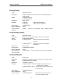
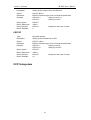
1.3 Chassis
ML1800 main box operates six modules installed, each module takes 1 to 2
installation positions. The size of the installation position is associated with a specific
module. Specification of Chassis is as Table 1- 1.
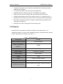
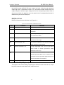
Table 1- 1 chassis specification
Part Number
ML1800
Module installation position
6 from the bottom
Power(all modules
1800W
installed)
Communication interface
RS232, GPIB (optional)
Module options
FT66103A, FT66105A
Power voltage
220V AC/50Hz
weight
16kg
size
570(D) × 433(W) ×190(H)
Operation temperature
0°C~40°C
Indoor operation and design, maximum humidity
Operation environment
90%
2
Intepro Systems
ML1800 User Manual
1.4 Panel Introduction
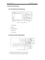
1.4.1 Front Panel Introduction
Figure 1- 1 Front Panel of Electronic Load
1.
Power switch
2.
Display
3.
Numeric keypad
4.
Rotary knob
5.
Function keys
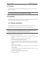
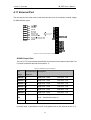
1.4.2 Rear Panel Introduction
Figure 1- 2 Rear Panel of Electronic Load
1.
SENSE input interface (positive and negative polarity)
2.
Load input interface (positive and negative polarity)
3
Intepro Systems
ML1800 User Manual
3.
Fuse
4.
AC input connector
5.
NG/GO output interface
6.
DIGITAL I/O interface
7.
GPIB bus interface
8.
RS232 interface
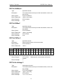
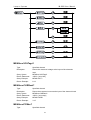
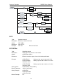
1.5 Module Introduction
FT66103A and FT66105A can both be installed in ML1800. Each module has
independent channel number and input terminal, and can be controlled separately or
simultaneously by the chassis.
Each module has two test input terminals (plus and minus) and remote sense terminal.
General features and operation ranges are listed in Table 1- 2.
Table 1- 2 Module General Specification
Model Number
FT66103A
FT66105A
FT66106A
FT66108A
Input Current
0-60A
0-10A
0-120A
0-20A
Input Voltage
0-80V
0-500V
0-80V
0-500V
Max power
300W
300W
600W
600W
CC Range
6A/60A
1A/10A
12A/120A
2A/20A
CV Range
16V/80V
50V/500V
16V/80V
50V/500V
0.025~100Ω(16V)
0.5~1875Ω(50V)
12. 5mΩ~50Ω(16V)
0.25~937.5Ω(50V)
0.625~2500Ω(80V)
25~93600Ω(500V)
0.3125~1250Ω(80V)
12.5~46.8KΩ(500V)
CP Range
300W
300W
600W
600W
LED Mode Range
16V/80V
50V/500V
16V/80V
50V/500V
Installation Position
1
1
2
2
CR Range
Sampling
Local sampling or remote sampling
Protection
OVP, OCP, OPP, OTP and input reverse connection protection
4
Intepro Systems
ML1800 User Manual
2 Installation
This chart describes how to install ML1800 multiple channel programmable DC
electronic load, and introduces the boot check procedures and cautions of
application.
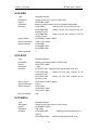
2.1 Inspection
After receiving the electronic load, please check the equipment according to the
following steps:
Check if any damage caused during the transport.
If the box or the protective pad is seriously damaged, please immediately contact an
Intepro authorized dealer or customer service department.
Note:please do not send the equipment back before the offer.
■ Accessories inspection
Make sure you also receive the accessories as below:
Figure 2- 1 Accessories
Accessories
Power cord and fuse
Description
Access to 110 or 220V AC power
supply
RS232 interface cable
Access to PC
User manual
Include installation, operation
information
CD
Software and technical information
Warranty card and after sale
Warranty and after sale service
service guide
information
If there is anything missing or damaged, please immediately contact an Intepro authorized
dealer or customer service department.
■ Machine inspection
If the load chassis is damaged or operates abnormally, please immediately contact an Intepro
authorized dealer or customer service department.
5
Intepro Systems
ML1800 User Manual
2.2 Cleaning
If you need to clean the external card cage, please wipe gently with a dry or non-scented cloth, do
not wipe the inside part.
Warning:Disconnect the power supply before cleaning!
2.3 Installation
Electronic load dissipates heat through the cooling fan, please ensure there is at least a 15cm space
from the upper side and all around with other objects for air circulation.
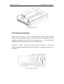
2.3.1 Module Installation
Module installation must start from the first slot position close to the main board, others are
sequentially installed. The installation methods of all types of modules are the same.
Warning:When removing or installing module, please follow the standard anti-static work
routine, avoid touching the connecting terminal and the circuit board.
The installation method and steps are as follows:
1.
Turn off the power supply of the chassis, disconnect the power line and all connection
terminal
2.
Release the screw cap with a screwdriver and remove the cover
3.
Remove all the packing material inside the chassis
4.
Wear anti-static bracelet, seize the module input terminal and fix the screw hole position
5.
Install the module from the first slot position close to the main board sequentially as in
figure 2-1
6.
Install all screws to fix module
7.
Connect the wire to the terminal, then insert the wire into the module ,and ensure a
proper connection
8.
If need to install other module, Please install the module according to steps 4 – 7 to the
slot right next to the former one
9.
After all the modules are installed, install the load cover
10. Reconnect the power line.
6
Intepro Systems
ML1800 User Manual
Figure 2- 1Module Installation
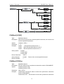
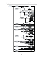
2.3.2 Channel Number
Module channel number is up to the installation position. Module channel number
closest to the motherboard is always 1, the other modules in accordance with the
motherboard distance from near to far are numbered 2 to 6. The module which
occupies two positions will still have only one channel number.
As Figure 2- 2 shown:The channel number of the first module is 1. The second
module occupies two positions and channel number is 2, if installation continues, the
number is 3.
Figure 2- 2 module channel number
7
Intepro Systems
ML1800 User Manual
2.3.3 Mainframe Installation
The electronic load offers both workbench and rack mountable installation ways.
Please ensure there is 15cm space at least from the upper side and all around with
other objects for air circulation. For exact size of the chassis please refer to Figure
Table 1- 1.
Workbench Installation
Put the electronic load on the workbench, than install the tripod to ensure there is
enough vertical space between the chassis and the workbench for air circulation.
Rack mountable Installation
Electronic loads can be installed into 19” rack. Please make sure there is at least
15cm space between the load and the other instrument which will be mounted above
the load for adequate air circulation.
For installation frame package, please contact an Intepro authorized sales agent.
2.3.4 Input Connection
Warning:To ensure the security and accuracy of test,the wire resistance
between the electronic load and power supply under test should be as low as
possible to ensure the wire is not overheat when short circuit current passing.
During the test,there will be higher current through the connection wire, which will
produce a certain pressure drop and heat on the wire. When the connection load and unit
are under test, the connection wire diameter needs to be considered in order to guarantee
the measurement precision and test security. Two small wires will impact the test accuracy;
the large heat dissipation may cause a safety hazard. Standard copper wire is ideal for
connection wire, Table 2- 2 lists the maximum current that copper wires of different
diameters can bear, please refer to the list of content to choose appropriate pressure drop
wires, please ensure the connecting line is not more than 0.5V when load modules work.
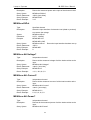
Table 2- 2 Copper wire diameter and the maximum current it can bear
2
Diameter(mm )
Current(Unit A)
Remarks
2.5
25
1. If use aluminum wire, the maximum load current is
8
Intepro Systems
ML1800 User Manual
4.0
30
about 84% of the same diameter copper wire.
6.0
40
2. If a plurality of wires bundled together, the
8.0
55
maximum load will be reduced. Calculation of actual
14
70
load current
22
95
2 wires:2×94%×rated current carrying capacity
30
100
3 wires:3×89%×rated current carrying capacity
38
125
4 wires:4×83%×rated current carrying capacity
50
145
of a plurality of wires as below:
5 wires:5×76%×rated current carrying capacity
3. Maximum temperature
60
Ambient temperature:50℃
165
Connection wire temperature:85℃
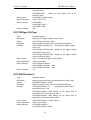
2.4 AC Input Requirements
Rated input voltage of the electronic load is either 115VAC±10% OR 220VAC±10%;
Frequency is 50 or 60 Hz.
The power supply input wire is 3 core cables with grounding protection. If there are no
appropriate earth plug, do not connect the load.
There is a power supply molded cable matching your local voltage included in
accessories. If the power input line and the power supply AC input end does not
match, please immediately contact an Intepro authorized dealer or customer service
department.
2.5 Power-on Self-test
Before operating the load, please confirm the following:
1.
Mark of the AC input range for the AC input socket:Either 100-130 VAC or
200V~240V AC
2.
Power line is connected to the AC input socket.
Warning:Electronic load is chassis grounded through three core power line.
Before load operating, please confirm the load good grounding.
9
Intepro Systems
ML1800 User Manual
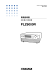
When the load power on, the screen will display the LOGO picture, and then displays
the load model and the voltage and current monitor interface.
Figure 2- 3 Load Monitor Interface
If the monitoring interface prompt "LOST", it means the calibration data is lost.
If the load does not start, the following methods can help you find the possible
problems:
1) Check if the power line is connected.
2) Check if the power line is connected and the power switch is turned on.
3) Check if the fuse of the load is burnt.
If fuse is burnt,please replace it.
Please open the small plastic cover, which is on the rear panel of the load and on the
left side of the power source socket, than replace the fuse. The fuse position is as
Figure 1-1 shown.
More information, Please contact the Intepro technical support department.
2.6 Connections
2.6.1 Input Connection
10
Intepro Systems
ML1800 User Manual
Warning:To meet the safety requirements, electronic load line must be
sufficient to withstand the maximum short-circuit current connecting to other
devices, but do not produce overheat phenomenon.
The DC load input connection is made by the “+”and “–” on the real panel of the load
and the equipment under test. With the input connection, attention must be paid on
diameter, length and polarity of input connection wire. Wire diameter that is too small can
affect the test precision, and excessive heat may cause a safety hazard. Copper line is
normally used for connection line, and it must be short and thick to ensure the DC voltage
drop is not more than 0.5V when the load is drawing current.
Warning:To meet the load requirements of higher performance and slope,the
inductance of the wire between the equipment under test and load must be less
than 5.0uh.
2.6.2 Sampling Connection
The load has two voltage measurement modes, which are remote sampling and local
sampling. Sampling mode can be selected from "voltage sampling" for switch option
under "system settings" menu.
local sampling
When the load is light, local sampling modes is available for input voltage
measurements.
remote sampling
When the load works, the input current will produce a certain voltage drop on the
contact resistance of connection wires and port and wire, which will affect the
accuracy of load voltage measurement. When the load is on the CV, CR, and CP
function and need accurate measurement, remote sampling mode is recommended.
Remote sampling terminal (SENSE+ and SENSE-) need to be directly connected
to the voltage output of the equipment under test for remote sampling Line connection
as shown in Figure 2- 4.
11
Intepro Systems
ML1800 User Manual
Figure 2- 4 remote sampling line connection
2.6.3 Parallel Connection
When the power or current of the power supply under test exceeds the specification
of the electronic load, 2 or more electronic loads input can be paralleled to increase the
current and power carry of the load. Electronic loads can be performed in parallel in the
CC, CR and CP mode, but can't achieve the parallel operation in CV mode. During
parallel operation, the measured output power is equal to the sum of all parallel load
power consumption. To take the constant current function for instance, two loads
connected in parallel, a principal value is set to 20A, the other one is set to 30A, than
the measured power will be on the 50A output current.
Figure 2- 5 load parallel line connection
12
3 Functions and Features
This chapter main describe the main functions and features of the electronic load.
You will have deeper knowledge on ML1800 series electronic load by reading this
chapter.
3.1 Control Mode
Electronic load offer two control modes:local control and remote control. Under local
control mode, the user main operate and set through the panel of the electronic load
and check the load status through the liquid display; Under remote control mode, the
user main operate and set through various interfaces and program commands
offered by the electronic load.
3.1.1 Local Control Mode
When the load turned on, default mode is local control mode. The user can operate
the load through the panel keypad under local control mode. The liquid display
provides users parameters, measurement display, and state indicator display
function.
Some parameters only can be set under local control mode, which include:
Remote communication interface of electronic load——RS232, GPIB (option);
GPIB address,serial baud rate and calibration mode.
3.1.2 Remote Control Mode
To enter the remote control mode of the electronic load,please select the right
interface mode first:GPIB or RS232, and connect the wire between the control device
and electronic load. The configured remote control parameters must be consistent
with the settings of the control device. When receiving the programming commands,
the electronic load will be switched to remote control mode automatically.
All the buttons on the panel of the load will be shielded under remote control mode,
and the load only can be controlled by programming commands. If you want to return
to local control mode, press "Shift" + "9" key.
13
Intepro Systems
ML1800 User Manual
3.2 Test Functions
5 modes are included in the test function of electronic load:
Constant current mode(CC)
Constant voltage mode (CV)
Constant resistance mode (CR)
Constant power mode (CP)
LED mode
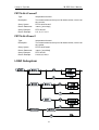
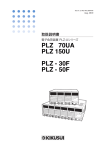
3.2.1 CC Mode
In the constant current mode, the load will consume constant current regardless of
the input voltage. Working curve is as shown in Figure 3- 1.
Figure 3- 1 constant current mode
The constant current mode is with high and low ranges. In low range, the input control
accuracy and resolution is high; High range can achieve wide load range. The load
range can be switched by changing the parameter in “mode settings” menu.
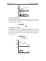
3.2.1.1 Steady State Test
Each range of steady state constant current mode has two values (A/B) for constant
current mode. The A value and B value are switched by pressing "A/B" key. The
rising / falling slope decide the speed of the load from one set value to another set
value, as shown in Figure 3- 2.
14
Intepro Systems
ML1800 User Manual
Figure 3- 2 steady state constant current mode
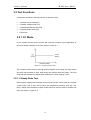
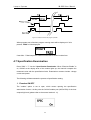
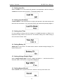
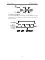
3.2.1.2 Transient Test
The transient test function allows the load to switch the set parameters (main value
and transient value) according to the set rule, which is ideal for transient test of power
supply. As shown in Figure 3- 3.
Figure 3- 3 transient constant current mode
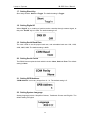
3.2.2 Constant Voltage Mode (CV)
In the constant voltage mode, the load will consume enough current to make input
voltage maintained at the set value, the working curve as shown in figure 3-4.
Figure 3- 4 constant voltage mode
The constant voltage mode is with high and low ranges (CVL and CVH), which can be
15
Intepro Systems
ML1800 User Manual
switched by the parameters in the “mode settings” menu. Two voltage values can be
switched by pressing “A/B” key under constant voltage.
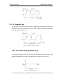
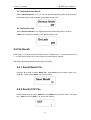
3.2.3 Constant Resistance Mode (CR)
In the constant resistance mode, the load is equivalent to a constant resistor, the
input current of which will be adjusted according to the change of the input voltage.
Working curve shown in figure 3-5.
Figure 3- 5 constant resistance mode
Constant resistance mode has high and low ranges (CRH and CRL), corresponding
to the two range of the voltage range under CV mode. Load range can be switched by
changing the parameters in “setting mode” menu. Two resistance values can be
switched by pressing “A/B” key.
3.2.4 Constant Power Mode (CP)
In the constant power mode, the load will consume a certain constant power. The
input current will be adjusted linearly according to the change of the input voltage to
ensure power consumption is unchanged, working curve as shown in Figure 3-6.
Figure 3- 6 constant power mode
Constant power mode only has one range. Two power value can be switched by
pressing “A/B” key.
16
Intepro Systems
ML1800 User Manual
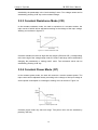
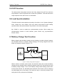
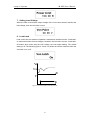
3.2.5 LED Mode
LED mode is mainly used for LED driver test. When the UUT voltage exceeds a
certain limited value Vf, the load will operate in approximately constant resistance
mode. The working curve is shown in Figure 3-7.
Figure 3- 7 LED mode
LED mode has high and low ranges (LEDH and LEDL),corresponding to the working
voltage. Load range can be switched by changing the parameters in “setting mode”
menu.
3.3 Apply Function
FT66100 offers a variety of application mode to adapt to the tests under special
cases, Including four modes:
Constant current soft starting mode (CC Rise)
Constant voltage soft starting mode (CV Rise)
Constant current to constant voltage mode (CC TO CV)
Constant resistance to constant voltage mode (CR TO CV)
3.3.1 Constant Current Soft Starting Mode (CC Rise)
Constant current soft starting mode is equivalent to an inductive load, and the
simulated inductance is proportional to the rise time of the soft starting. The working
curve is shown in Figure 3- 8.
17
Intepro Systems
ML1800 User Manual
Figure 3- 8 constant current soft starting mode
Constant current soft starting mode has two ranges (CCL Rise and CCH Rise).
3.3.2 Constant Voltage Soft Starting Mode(CV Rise)
Constant current soft start mode is equivalent to a capacitive load and the simulated
capacitance is proportional to the rise time of the soft start. The UUT might be
impacted instantly by high current in this mode. The working curve is shown in Figure
3-9.
Figure 3- 9 constant current soft start mode
Constant current soft starting mode has two ranges (CVL Rise and CVH Rise).
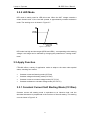
3.3.3 CC To CV
Constant current to constant voltage mode can make the battery discharge more fully.
The working curve is shown in Figure 3-10.
18
Intepro Systems
ML1800 User Manual
Figure 3- 10 CC to CV
CC to CV mode has two ranges (CCL To CV and CCH To CV).
3.3.4 Constant Resistance to Constant Voltage
Mode (CR To CV)
Constant resistance to constant voltage mode can make the battery discharge more.
The working curve is shown in Figure 3- 11.
Figure 3- 11 CR to CV
CR to CV mode has two ranges (CRL To CV and CRH To CV).
3.4 Programming Function
Under programming mode, load executes many test items on the equipment
according to the file. After the test, Pass or Fail will be displayed for test result. The
advantage of programming mode is particularly evident in the product inspection,
which can significantly improve the efficiency of product inspection. Load can store
up to 10 programs, each program contains 10 series, a total of 100 archives. If a
single program sequence is not enough to test the UUT, program chain function can
help get more sequence for test.
19
Intepro Systems
ML1800 User Manual
3.5 OCP Function
The load provides rising slope current to test if the voltage of the UUT can reach the
end potential in order to determine the normal OCP protection. This test checks the
output response of the UUT when it is overloaded.
3.6 Load Synchronization
FT66100 electronic load comprises a plurality of modules. In the "Systems Settings"
menu, setting the "sync enable" open can realize multi-module On/Off loading
synchronously. Load synchronization only effects in the mode and program.
Key "SYNC" is used to enable the synchronization function. When setting the
synchronization function of each channel, press "SYNC" key, synchronization
function effects.
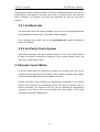
3.7 Battery Charge Test Function
Battery charging test includes constant current charging, constant voltage charging.
and constant current to constant voltage charging. The wiring diagram when the
battery is charging is shown in figure 3- 12.
Figure 3- 12 battery charging test wiring diagram
When it works in constant current mode, the electronic load can be used for battery
constant current charging. When working in battery mode of CV, the load can be used
for battery voltage charge. To turn on the battery voltage mode settings, please refer
to the manual section 4.8. ML1800 series electronic load can be used for charging
and discharging test of the battery. The loads are easy to control by software, and
easily achieve life cycling test of the battery.
20
Intepro Systems
ML1800 User Manual
3.8 Input Control
3.8.1 Turn on/off the load
Press “On/Off” key to change the input state of the electronic load.
3.8.2 Short Circuit
Electronic load can be simulated to test the protection performance of the UUT. When
the load is short circuited, the current it consumed depends on the current operation
mode and current range. Under CC and CP modes, the maximum short circuit current
is 105% of the current range; Under CV modes, short circuit operation is equivalent to
setting the constant voltage value of the load 0V. Short circuit operation does not
change the current settings. The load will return to the previous state when exiting
short circuit operation. When short circuit, during the first 200ms the maximum power
the load consumes is 2 times of the rated power.
FT66100 has two short circuit modes: Hold and Toggle
Press the "Short" load short-circuit to select Hold, releasing the button will exit
the short-circuit condition.
Press the "Short" load short circuit to select Toggle, then press "Short" again to
exit the short-circuit condition.
Short circuit operation only effect in Mode. If you press the “SYNC” key, the short
circuit operation is only valid for the current module.
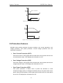
3.8.3 Loading/Unloading Voltage
When the UUT voltage rise or fall speed is slow, setting the "load voltage" can
implement UUT protection. When set, only when the measured power supply voltage
rises to higher than the set “load voltage” will the load starts drawing current. When
the “load voltage” drops below the setting, load stops drawing current. When the
"load latch" and "unload enable" are turned on; When voltage drops below the
“unloading voltage”, the load will stop drawing current. The working curve is shown
below. Loading / unloading voltage setting is only useful in CC Mode.
21
Intepro Systems
ML1800 User Manual
Figure 3- 13 Von Loading(Von non-locking)
Figure 3- 14 Von Unloading(Von non-locking)
3.9 Protection Features
ML1800 series provide protection functions including: over current protection, over
voltage protection, over power protection, reverse voltage protection and over
temperature protection:
Over Current Protection (OCP)
If the input current is 105% higher than the rated value, the load will enter the over
current protection state. VFD displays the information as “OC”.
Over Voltage Protection (OVP)
If the input voltage is 105% higher than the rated value, the load will enter the over
voltage protection state. VFD displays the information as “OV”.
Over Power Protection (OPP)
Over power protection is mainly used to protect the hardware to avoid
components aging quickly or damaged caused by being in long time state of over
power. When the input power is 105% higher than the rated value, the input will be
turned off, VFD displays the information as “OP”.
22
Intepro Systems
ML1800 User Manual
Reverse Voltage Protection (rEVP)
When the polarity of the power supply to be measured is not connected properly,
VFD displays the information as "rEV", and an alarm sound can be heard. The
electronic load will be in a conducting state. The maximum permissible reverse
current is the same as the rated current of the load. If the reverse current
exceeds the rated current, it may cause damage to the electronic load.
Over Temperature Protection (OT)
The load is with internal temperature detection circuit, when the internal
temperature exceeds the safety limit, the load will close the input and “OT” will be
prompted on the screen. A fan will be at full load operation as soon as possible to
cool the load.
Warning:Please do not place the AC power output end to the input end of
the load, and ensure the input voltage should not exceed the maximum rated input
voltage.
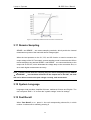
3.10 Slew Rate and Minimum Transition Time
Conversion slew rate defines the switching speed between value A and value B in the
constant current, constant resistance, and constant power function of the load. The
slew rate of the CC, CR, and CP functions can be set up. The time of one x value
converted to another setting value can be set by changing slew rate of the electronic
load. Figure 3-15 describes the relationship between slew rate set value and actual
converting time.
In CC, CR, and CP functions; Rise and fall slew rate can be set up. If the constant
current transient mode is on, the load will convert between the rise slew rate and fall
slew rate. Slope value will determine the minimum conversion time between the
principal value and the transient value. When the slew rate is set to the maximum
value, the conversion time between the principal value and the transient value is the
minimum.
23
Intepro Systems
ML1800 User Manual
Figure 3- 15 relationship between slew rate and actual conversion time
3.11 Remote Sampling
SENSE+and SENSE- are remote sampling terminals, which provide the internal
measurement system of the load with remote voltage signal.
When the load operates on the CV, CR, and CP function or need to measure the
output voltage of the UUT accurately, remote sampling mode is recommended. When
remote sampling rate, terminal SENSE+and SENSE- are connected directly to the
output end of the UUT, which eliminates the voltage drop on the connection wire, so
as to reach higher measurement accuracy.
Note:If select remote mode for sampling way,but remote sampling terminal SENSE
+ and SENSE - has not been connected to the output end of the UUT, the load
will not be able to measure the port voltage correctly, and cannot work.
3.12 System Language
Languages load provides: simplified Chinese, traditional Chinese and English. The
user can press "Shift" + "6" to enter the "system settings" menu for settings.
3.13 Fast Recall
When “Fast Recall” is on,press 0~9 to call corresponding schema file, in which
number 10 schema file is called by pressing 0.
24
Intepro Systems
ML1800 User Manual
3.14 Turn-On Keypad Lock
FT66100 electronic load support keyboard lock function. Press "Shift" + "8" key,
open/close the keyboard lock. When Keyboard is locked, only “On/Off”, “Short”,
“Shift” and “SYNC” can be operated. Keyboard lock state can be configured by
setting “Boot Keypad Lock” option in “System Settings” menu.
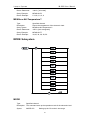
3.15 Restore Factory Settings
The load provides restore factory setting function. Detailed factory settings with
parameters are as shown in table 3-1.
Table 3- 1 restore factory default parameters table
Item
Parameters
Sync enable
On
Remote sampling
Off
CC voltage range
High
Current sampling range
High
Power, current limit
Maximum
Load/unload voltage
0V
Load latch/unload enable
Off
Power load
Off
Power up mode
Mode
Load time
0s
Battery constant voltage
Off
Keyboard sound
On
Short circuit key
Toggle
Digital port / fast call / boot
keyboard lock
Off
Steps of restore factory default settings are as follows:
1. Press “Shift”+“4” into document call interface;
2. In “Schema File” option,enter 101,and press Enter to confirm.
Note:After restoring factory settings, need power on again。
25
4 Operation
This chapter describes operation methods of ML1800 electronic load.
4.1 Keypad
Figure 4- 1keypad of electronic load
Electronic load keypad is divided into three areas: numeric keypad, function keypad,
knob. The following are introduced in detail.
4.1.1 Numeric Keypad
Figure 4- 1 Numeric keys introduction
Key
Function
0 ~ 9
0 through 9 are used for entering numeric
values
·
Decimal point
▲▼
Scrolling keys let you move through the
commands in the present select function menu,
bring up the next command in the list. On setting
parameters, these two keys are used to control
the movement of a cursor among digital.
26
Intepro Systems
ML1800 User Manual
Enter
Confirmation key,is used to enter setup option
or confirm input and exit the settings.
←
Remove the set data
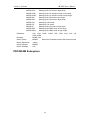
4.1.2 Function Keys
Function keys compromise single function keys and composite function keys, the
introduction is as follows.
Figure 4- 2 single function keys introduction
Key
Function
CH1~CH6
Select channel need to be edited
Mode
Enter “Mode Settings” menu
SYNC
Synchronization key, press this key, all modules
with sync enable on can do On/Off, Short and
save in the recall synchronously.
Shift
Second function switching key
Esc
Return to the previous menu.
A/B
Select steady state operation, switch A/B
Short
Short circuit key, press this key will make all
channels of the electronic load to enter short
circuit state.
On/Off
Input switch
Figure 4- 3 Composite function keys introduction
Composite keys
Function
Shift+1 (Save)
Enter the save menu
Shift+2 (Prog)
Enter the program edit menu
Shift+3 (OCP)
Enter OCP menu
Shift+4 (Recall)
Enter recall menu
Shift+5 (Apply)
Enter application settings menu
Shift+6 (Config)
Enter system setup menu
Shift+7 (SPEC)
Enter specification check menu
Shift+8 (Lock)
Enter / Exit the keyboard lock
mode
Shift+9 (Local)
Return to the local control mode
4.2 Channel Selection
Press "CH1" to "CH6" and select one channel for manual operation. You can find
27
Intepro Systems
ML1800 User Manual
channel number at section 2.3.2. The host will scan the installed module and module
type after boot. If there are no modules installed in the mainframe, “Can not find any
module” will be shown on the display. Edit channel setting, you must first select the
channel. If the channel does not exist, you can not operate.
4.3 Setting up Operation Mode
Press “Mode” to enter “Mode” menu. Users can set the load working modes: CC, CV,
CR, CP or LED mode.
4.3.1 Constant Current Operation (CC)
There are four levels for constant current (CC) operation:
Static low range(CCL)
Static high range (CCH)
Transient low range (CCDL)
Transient high range (CCDH)
The following will demonstrate the constant current operation process. Before the
operation, first select the channel, and enter the "Mode " menu.
1. Select CC range
Press▲▼ or knob to choose “Mode”, and press Enter key to confirm. Choose “CCL”
or press numeric key “1” and confirm.
2. Setting Current Value
Press▲▼ or knob to choose “CCL1”, enter 1 and confirm. Choose “CCL2”, enter 2
and confirm.
28
Intepro Systems
ML1800 User Manual
3. Setting Slew Rate
Press ▲▼or knob to choose “rise slew rate”, enter 1 and confirm. Choose “fall slew
rate”, enter 2 and confirm.
4. Setting Transient Functional Cycle
In CCDL or CCDH mode, main value / transient pulse width need to be set, the range
is 0.025ms ~ 50000ms. Press▲▼ or know to choose “T1”, enter 10 and confirm.
Choose “T2”, enter 20 and confirm.
4.3.2 Constant Voltage Operation (CV)
Constant voltage has (CV) high and low ranges:
CV low level (CVL)
CV high level (CVH)
Voltage is in volts (V) as a unit, the response rate can be set as fast (Fast), medium
(Medium) and slow (Slow). The following will demonstrate the constant voltage
operation process. Before the operation, first select the channel, and enter the
"mode" menu.
1. Select Constant Voltage Range
Press▲▼ or knob to choose “Mode”, and press Enter key to confirm. Choose “CVL”
or press numeric key “7” and confirm.
29
Intepro Systems
ML1800 User Manual
2. Setting Voltage Value
Press▲▼ or knob to choose “CVL1”, input, and press Enter to confirm. Choose
“CVL2”, enter 6 and confirm.
3. Setting Response Rate
Press▲▼ or knob to choose “Response”, Press▲▼ keys or knob to choose
response rate “Slow”, and press Enter to confirm.
4.3.3 Constant Resistance Operation (CR)
Constant resistance has (CV) high and low ranges:
CR low level (CRL)
CR high level (CRH)
The resistance is in ohms (Ω) as a unit, and the slew rate is in the amp / S (A/us) as a
unit. The following will demonstrate the operation process of constant resistance.
Before the operation, first select the channel, and enter the "Mode" menu.
1. Select Constant Voltage Range
Press▲▼ or knob to choose “Mode”, and press Enter key to confirm. Choose “CRL”
or numeric key“5”and confirm.
2. Setting Resistance Value
30
Intepro Systems
ML1800 User Manual
Press▲▼ or knob to choose “CRL1”, enter 1 and confirm. Choose “CRL 2”, enter 2
and confirm.
3. Setting Slew Rate
Press ▲▼or knob to choose “rise slew rate”,input 1 and confirm. Choose “fall slew
rate”, enter 2 and confirm.
4.3.4 Constant Power Operation (CP)
The power is in watts (W) as a unit, and the slew rate is in the amp / S (A/us) as a unit.
The following will demonstrate the operation process of constant power. Before the
operation, first select the channel, and enter the "Mode" menu.
1. Select Constant Power Mode
Press▲▼ or knob to choose “Mode”, and press Enter key to confirm. Choose “CP”
or numeric key“9”and confirm.
2. Setting Power Value
Press▲▼ or knob to choose “CP1”, enter 10 and confirm. Choose “CP2”, enter 20
and confirm.
31
Intepro Systems
ML1800 User Manual
3. Setting Slew Rate
Press ▲▼or knob to choose “rise slew rate”, enter 1 and confirm. Choose “fall
slew rate”, enter 2 and confirm.
4.3.5 LED Operation
LED mode has high and low ranges:
LED low level (LEDL)
LED high level (LEDH)
The following will demonstrate the operation process of LED mode. Before the
operation, first select the channel, and enter the "Mode" menu.
1. Select LED Level
Press▲▼ or knob to choose “Mode”, Press Enter key to confirm. Choose “LEDL”,
or press numeric key “0” and confirm.
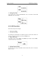
2. Setting Output Voltage
Set LED driver test voltage. Press▲▼ or knob to choose “Vo”, enter 10,and press
Enter to confirm.
32
Intepro Systems
ML1800 User Manual
3. Setting Output Current
Set LED driver test current. Press▲▼ or knob to choose “Io”, enter 0.5, and press
Enter to confirm.
4. Setting Forward Bias
Press▲▼ or knob to choose “Vf”, enter 5, and press Enter to confirm.
4.4 Setting Application Settings
Press“Shift”+“5”key to enter “Apply” menu. Users can set the load working modes: CC
soft start, CV soft start, CC to CV, or CR to CV.
4.4.1 Constant Current Soft Start Operation (CC
Rise)
Constant current soft start operation has high and low ranges:
Constant current soft start low range (CCL Rise)
Constant current soft start high range (CCH Rise)
Current is in Amp (A) as a unit, the slew in the Amp / Microsecond (A/us) as a unit,
voltage in volts (V) as a unit, and the rise time in milliseconds (MS) as the unit, its
time setting range: 0.1 ~ 10000ms.
The following will demonstrate the operation process of constant current soft start.
Before the operation, first select the channel, and enter the “Application” menu.
33
Intepro Systems
ML1800 User Manual
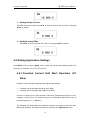
1. Select Constant Current Soft Start Function
Press▲▼ or knob to choose “Apply Select” and confirm. Choose “CCL Rise” and
confirm.
2. Setting Current Value
Press▲▼ or knob to choose “CCL1”, enter 1 and confirm.
3. Setting Rise Time
Press▲▼ or knob to choose “CCL Rise Time”, enter 1000,and press Enter key to
confirm.
4. Setting Slew Rate
Press ▲▼or knob to choose “rise slew rate”, enter 1 and confirm. Choose “fall slew
rate”, enter 2 and confirm.
4.4.2 Constant Voltage Soft Start Operation (CV
Rise)
Constant voltage soft start operation has high and low ranges:
Constant voltage soft start low range (CVL Rise)
Constant voltage soft start high range (CVH Rise)
The response rate is set as Fast, Medium and Slow, rise time setting range:
34
Intepro Systems
ML1800 User Manual
0.1~10000ms.
The following will demonstrate the operation process of constant voltage soft start.
Before the operation, first select the channel, and enter the “Application” menu.
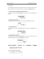
1. Select Constant Voltage Soft Start Function
Press▲▼ or knob to choose “Apply Select” and confirm. Choose “CVL Rise” and
confirm.
2. Setting Voltage Value
Press▲▼ or knob to choose “CVL1”, enter 10 and press Enter key to confirm.
3. Setting Rise Time
Press▲▼ or knob to choose “CVL Rise Time”, enter 1000, and press Enter key to
confirm.
4. Setting Response Rate
Press▲▼ or knob to choose “Response Rate”, then choose response rate to be
“Fast” through ▲▼ or knob, and press Enter key to confirm.
4.4.3 Constant
Current
Operation (CC To CV)
CC to CV operation has two ranges:
CC(low range)to CV(CCL To CV)
CC(high range)to CV(CCH To CV)
35
to
Constant
Voltage
Intepro Systems
ML1800 User Manual
The following will demonstrate the operation process of CC (low range) to CV. Before
the operation, first select the channel, and enter the “Apply” menu.
1. Select CC to CV Function
Press▲▼ or knob to choose “Apply Select” and confirm. Choose “CCL to CV” and
confirm.
2. Setting Current Value
Press▲▼ or knob to choose “CCL1”, enter 1 and press Enter key to confirm.
3. Setting Slew Rate
Press ▲▼or knob to choose “rise slew rate”, enter 1 and confirm. Choose “fall slew
rate”, enter 2 and confirm.
4. Setting Mode Conversion Voltage
Press ▲▼ or knob to choose “Conversion Voltage”, enter 10 and press Enter key
to confirm.
5. Setting Response Rate
Press▲▼ or knob to choose “Response”, then choose response rate to be “Fast”
and press Enter key to confirm.
36
Intepro Systems
ML1800 User Manual
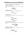
4.4.4 Constant Resistance to Constant Voltage
Operation (CR To CV)
CR to CV operation has two ranges:
CR (low range) to CV (CRL To CV)
CR (high range) to CV (CRH To CV)
The following will demonstrate the operation process of CR (low range) to CV. Before
the operation, first select the channel, and enter the “Apply” menu.
1. Select CR to CV Function
Press▲▼ or knob to choose “Apply Select” and confirm. Choose “CRL to CV” and
confirm.
2. Setting Resistance Value
Press▲▼ or knob to choose “CRL1”, enter 10 and press Enter key to confirm.
3. Setting Slew Rate
Press ▲▼or knob to choose “rise slew rate”, enter 1 and confirm. Choose “fall slew
rate”, enter 2 and confirm.
4. Setting Mode Conversion Voltage
Press ▲▼or knob to choose “Conversion Voltage”, enter 10 and press Enter key to
confirm.
37
Intepro Systems
ML1800 User Manual
5. Setting Response Rate
Press▲▼ or knob to choose “Response”, then choose response rate to be “Fast”,
and press Enter key to confirm.
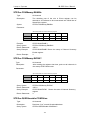
4.5 Setting OCP
Press “Shift” “3”key to enter “OCP” menu. Parameters need to be set include: Start
current (I-Start), End current (I-End): they are set up according to the selection of CCH
or CCL. OCP only work when I-Start<I-End.
Increasing step No.(NO.Step):1~100
Dwell Time(DwellT):500~1000ms
Step current OCP test:
OCP Accuracy =
I୬ୢ − Iୗ୲ୟ୰୲
NO. Step
Trigger voltage (VOLT-Trig): set according to the user's requirements, only work when
the trigger voltage is lower than the measured voltage.
Specify low limit (SPEC_L), Specify Upper Limit (SPEC_H): set according to the user's
requirements.
After parameters are set, press “On/Off”key to start test.
Test results are up to the current when the measured voltage reachesthe measured
voltage:When the current is within the range, "Pass" shown on the screen, otherwise
screen shows "Fail".
The following will demonstrate the operation process of OCP.
1. Setting Start and End Current
Press▲▼ or knob to choose “I-Start”, enter 1 and confirm. Choose “I-end”, enter 10
and confirm.
38
Intepro Systems
ML1800 User Manual
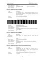
2. Setting Increasing Step Numbers and Dwell Time
Press▲▼ or knob to choose “NO.Step”, enter 100 and confirm. Choose “DwellT”,
enter 500 and confirm.
3. Setting Trigger Voltage
Press▲▼ or knob to choose “Trigger Voltage”, then press Enter key. Enter 3.6 and
confirm.
4. Setting Specified Upper and Lower Limit of OCP
Press▲▼ or knob to choose “SPEC-L”, enter 8.8 and press Enter key. Press▲▼ or
knob to choose “SPEC-H”, enter 9 and press Enter key.
When parameter setting is completed, press "On/Off" to start the OCP test. When the
test is completed, test results Pass or Fail as well as OCP voltage and current value
will be shown. Press "Shift" + "Clear" can remove the test results; press "On/Off" to
start a test again.
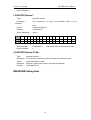
4.6 Programming
Electronic load can save the mode test into file, then executed automatically by
programming.
39
Intepro Systems
ML1800 User Manual
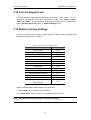
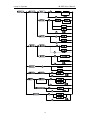
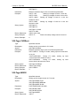
A total of 10 programs (1 ~ 10), each program has 10 sequences, which is marked
from 1 to 100 in schema archives. The table below shows the relationship between
program sequence and the corresponding schema archives.
Table 4- 4 Relationship between program sequence and the corresponding schema archives
Program 1
1
2
3
4
5
6
7
8
9
10
1
2
3
4
5
6
7
8
9
10
1
2
3
4
5
6
7
8
9
10
11
12
13
14
15
16
17
18
19
20
1
2
3
4
5
6
7
8
9
10
91
92
93
94
95
96
97
98
99
100
sequence No.
Corresponding file
No.
Program 2
sequence No.
Corresponding file
No.
:
:
Program 10
sequence No.
Corresponding file
No.
During programming operation, corresponding file parameters must be set first. If a
program sequence is not sufficient to complete the test, you can use the program
chain function to get more sequences.
4.6.1 Program Edit
Press“Shift”+“2”key to enter “Program Edit” menu. The following will demonstrate
the process of program edit.
1. Recall Program Files
Input 1~10 means to recall program 1~program 10. In "program files" option to
recall program 1 and confirm.
2. Channel Activation
40
Intepro Systems
ML1800 User Manual
Only when the module exists and the synchronization (SYNC.RUN) option in
configuration menu is set to on, program test can be run.
Press ▲▼ or knob to select “Active CHAN”,Press 1~6 to choose active channel to
be effective or ineffective, and confirm.
3. Setting Program Chains
Program chains function help get more test sequences. Enter 1 ~ 10 implies that the
link program 1~ program 10, enter 0 represents no program chain.
To choose “Chain Number” option and enter 2 represents linking to program 2, then
press Enter to confirm.
4. Setting Check Time Delay
Sequence Pass/Failure delay time is used to set delay time for P/F detection, the
range is 0 to 30 seconds (S).
Input 1 at “P/F delay”, which means detection delay time is set to 1s and confirm.
5. Setting Load ON/OF Time
When the program is executed, with and without load time sequence control load on /
off, On/Off time range is 0 ~ 60 seconds (s).
Press▲ ▼ button or knob to select "On time", enter 2 and confirm. Select the "Off
Time" option, enter 0 and confirm.
41
Intepro Systems
ML1800 User Manual
6. Setting Edit Steps
Input 1 ~ 10 represents calling sequence 1~ sequence 10.
Press▲ ▼ button or knob to select “SEQ”, enter 1, and press Enter key to confirm.
7. Setting Sequence Mode
Three modes to control the execution ways of sequences:
Skip: Skip sequence and the input state of the load will be kept the same.
Auto: Use loading/unloading time to control the loading and unloading of the load.
When loading/unloading time pass, the load will skip to the next sequence
automatically.
Manual: Use ▲ ▼ or 0 to 9 number keys to control the execution sequence. Press
numeric key to select random execution sequence number. 0 represents sequence
10.
External:When triggering signal, D7 of DIGITAL I/O is for external triggering to
control execution sequence.
8. Setting Short Circuit Channel
Press▲ ▼ button or knob to select "Short CHNN", and press Enter to confirm,
Press 1~6 keys to turn on/off the short circuit function of corresponding modules and
then confirm.
42
Intepro Systems
ML1800 User Manual
9. Setting Short Time
The short time range is 0 ~ 60 seconds (s).
Press▲ ▼ button or knob to select "Short Time", enter 1and confirm, set the short
time to 1s.
10. Repeat step 6 to 9 until the program editing is finished
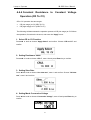
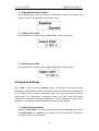
4.6.2 Program Operation
When the program function is selected, press "On/Off" to operate the program. The
program operation status is displayed:
PROG:Displays the program number of the current channel operation.
SEQ:Displays the sequence number of the operation.
Load: Displays the input status.
Mode: Displays the operation mode.
QC:Displays the test results compared with the standard inspection.
Sequence when the program operates is as in Figure 4- 2.
43
Intepro Systems
ML1800 User Manual
Figure 4- 2 Sequence when the program operates
When program test is finished, program running result will be displayed. If all is
passed, “PASS” will be displayed.
If test fails,Failed sequence numbers of test will be shown in table form.
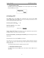
4.7 Specification Examination
Press "Shift" + "7" into the "Specification Examination. When “Examine Enable” is
on, GO/NG at the display area of the module lights up, the load will compare the
measured value with the specification limits. Examination contents include: voltage
current and power.
The following will demonstrate the process of specification setting.
1. Examine ON/OFF
The "enable" option is set to open, which means opening the specification
examination function. At this point the GO/NG enable port (NG/GO EN) of the host
outputs high level (please refer to the manual section 4.11).
44
Intepro Systems
ML1800 User Manual
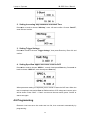
2. Setting Examination Content
Press ▲ ▼ button or knob to select the "Examination Content" and confirm, and
choose “Current” as examination content and confirm.
3. Setting Lower Limit
Press ▲ ▼ button or knob to select “Lower Limit”, enter 5 and confirm.
4. Setting Upper Limit
Press ▲ ▼ button or knob to select “Upper Limit”, enter 10 and confirm.
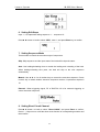
4.8 System Settings
Press "Shift" + "6" to enter the "Settings" menu. The electronic load provides many
configuration characteristics such as load voltage, current limit, synchronous operation etc.
To use these features, relative parameters need to be set in accordance with the
requirements. The configuration parameters include: the main value and module
configuration parameters. Channel configuration is stored separately, so must be set
separately. The following will demonstrate the process of system setting.
1. Setting Synchronization
When the "Sync Enable" on, load switch is controlled by the "On/Off" button. When
the "Sync Enable" off, "On/Off" are only valid for the current channel. Synchronous
operation is set to be on by default.
45
Intepro Systems
ML1800 User Manual
2. Setting Remote Sampling
"Remote Sampling" on means load voltage remote sampling, "Remote Sampling"
off means load voltage proximal sampling. Remote sampling eliminates the
connection voltage drop on connection wire so as to obtain higher measurement
accuracy. Default setting is on.
3. Setting CC Voltage Range
In CC mode, there are two kinds of read back voltage range. High range (High) is for
use in high voltage, low range (Low) is for use in low voltage, so as to obtain a better
voltage resolution. The voltage range of CC is high range (High) by default.
4. Setting Current Sampling Range
There are two “Current Sampling Range”. High range is for (High) CCH, low range
is for CCL. The default setting is high range (High).
5. Setting Current Limit
This function will limit the load current and the protection current in CV mode can not
exceeds the limit value. The default value is the maximum permitted current.
6. Setting Power Limit
This function will limit the maximum load power to be the power limit value. If the
power exceeds the limit value, the load stops loading. The default value is the
maximum permitted power.
46
Intepro Systems
ML1800 User Manual
7. Setting Load Voltage
When the load is ON and the output voltage of the unit to be measured reaches the
load voltage, then the load sinks current.
8. Load Latch
Load control has two modes of operation: latched and unlatched mode. "Load latch"
on means that when the load voltage is reached, the load sinks current; "Load latch"
off means when lower than the load voltage, the load stops loading. The default
setting is off. The following figure 4- 3 and 4- 4 shows the current waveform when the
Von latch is on or off.
Figure 4- 3 Current waveform when Von Latch On
47
Intepro Systems
ML1800 User Manual
Figure 4- 4 Current waveform when Von Latch On
9. Setting Unload Enable
“Load On” on means the measured voltage of UUT is lower than the unload voltage,
the load stops loading. “Load On” off means the unload voltage does not represent
any function. The default value is off.
10. Setting Unload Voltage
"Unload Enable" is set to be on, "Load Voltage" and "Load Latch" must be set first.
Load voltage must be greater than the unload voltage, and load latch must be opened
so that the unloading voltage effects. When the voltage is lower than the unload
voltage, load stop loading. Figure 4- 5 shows the waveform of the setting load and
unloading voltage.
Figure 4- 4 Set load current waveform of Von and Voff
48
Intepro Systems
ML1800 User Manual
11. Setting Load On
When “Load On” is on, the module will operate in correspondence with the setting of
“Load On” when the host is turned on. The default setting is off.
12. Setting Load On Mode
“Load On Mode” is set to be Mode, the module will operate in the latest setup mode
when the host is turned on. If it is set to be PROG, the module will operate program 1.
13. Setting Load Time
For time setting of timing mode, the range is 0 to 99999 seconds (s). Where in 0s
represents timing mode is not turned on. The default setting is 0s. When timing is
over, the screen shows “Over”.
14. Setting Battery CV
“Battery CV” is set to be on. The load can be used for constant voltage charging. The
default setting is off.
15. Setting Voltage Display Signs
When “Voltage Display Sign” is minus, voltage read back is “–“, and it accounts for a
character width, if set to plus, no sign will be displayed.
16. Setting Keypad Sound
When “Sound” is on, key-touch tone is on; when it is off, key-touch tone is on.
49
Intepro Systems
ML1800 User Manual
17. Setting Short Key
Short ways include: Hold and Toggle. The default setting is Toggle.
18. Setting Digital IO
When “Digi IO” is on, loading of module can be controlled through external signal, at
this point “On/Off” key is invalid. The default setting is off.
19. Setting Serial Baud Rate
The user needs to set the proper baud rate, and selectable baud rate: 600, 1200,
2400, 4800, 9600. The default setting is 9600.
20. Setting Serial Check
The RS232 has an optional check which includes: None, Odd and Even. The default
setting is None.
21. Setting GPIB Address
“GPIB Address” can be any integer from 0~31. The default setting is 5.
22. Setting System Language
Setting language include: Simplified Chinese, Traditional Chinese and English. The
default setting is English.
50
Intepro Systems
ML1800 User Manual
23. Setting Shortcut Recall
When “Shortcut Recall” is on, you can call the corresponding mode file by pressing
the number keys on the keyboard. The default setting is off.
24. Setting On Lock
When “Shortcut Recall” is on, digital keyboard is locked after reboot. There is
“Shift”+“8” on/off lock in addition. The default setting is off.
4.9 File Recall
Press "Shift" + "4" key to enter the "Recall" menu. FT66100 has 1 ~ 101 schema files and
1~10 OCP file for recall. No.101 file recall is to restore factory settings.
The following will demonstrate the process of file recall.
4.9.1 Recall Mode File
Press ▲ ▼ or knob to select “Mode File”, press Enter key to confirm. Input 10 to
recall No. 10 file. Press “Mode” key for file content.
4.9.2 Recall OCP File
Press ▲ ▼ or knob to select “OCP File”, press Enter key to confirm. Enter 1 to recall
No. 1 OCP file. Press “Shift” + “3” key for file content.
51
Intepro Systems
ML1800 User Manual
4.9.3 Fast Recall
In configuration menu, if “fast recall” is set to on, 1~10 mode files can be recalled by
pressing numeric key “0”~“9” directly. Wherein key “0” corresponds to No.10 mode
file.
Note:Fast recall function is only valid in mode page.
4.10 Save File
FT66100 has 1 ~ 10 schema files to save, and 1~10 program files and 1~10 OCP files
to save. The following will demonstrate the process of file recall.
4.10.1 Save Mode File
In “Mode” menu, Press “Shift” + “1” key to enter “Save” menu. Press▲▼ or knob to
select “Mode File”, and press Enter to confirm. Enter 10 and confirm.
4.10.2 Save Program File
In“Program Edit”menu, Press“Shift”+“1”key to enter “Save” menu. Press▲▼ or
knob to select “Program File”, and press Enter to confirm. Choose “Yes” and
confirm.
4.10.3 Save OCP File
In “OCP File” menu,Press “Shift” + “1” key to enter “Save” menu. Press▲▼ or knob
to select “OCP File”, and press Enter to confirm. Enter 10 and confirm.
52
Intepro Systems
ML1800 User Manual
4.11 External Port
The rear panel of the main board of the loads has two rows of connection terminal: digital
I/O AND NG/GO output.
Figure 4- 5 Load control connection terminal
GO/NG Output Port
The use of TTL level indicates specification test results of each channel are Pass/ Fail.
Functions of NG/GO terminal are as table 4- 5.
Figure 4- 5 NG/GO port function definition
Pin
Corresponding
Name
Channel
NG/GO 1
1
High level:Pass
Low level:Fail
NG/GO 2
2
High level:Pass
Low level:Fail
NG/GO 3
3
High level:Pass
Low level:Fail
NG/GO 4
4
High level:Pass
Low level:Fail
NG/GO 5
5
High level:Pass
Low level:Fail
NG/GO 6
6
High level:Pass
Low level:Fail
NG/GO
Enable
Low level : Specification check off
High
level:Specification check on
EN
GND
Description
Ground
NG/GO public place
In steady state, if specification check is off (please refer to the manual section 4.7),
53
Intepro Systems
ML1800 User Manual
the NG/GO enable (NG/GO EN) port outputs low level, while the other channels
output high level; if specification check is on, the NG/GO enable (NG/GO EN) port
outputs high level and the output voltage level of the corresponding channel is up to
check result. When the program runs, the output level of corresponding channel is
determined by the result of step test.
DIGITAL I/O Port
DIGITAL I/O port function definition is as Figure 4- 6.
Figure 4- 6 Function definition of DIGITAL I/O terminal
Port
Function
Remarks
D1
Load On/Off(O/P)
High level output at Load On, High level
D2
Total Pass(O/P)
High level pulse signal output if test items all channels
at Load Off.
are passed
D3
Total Fail(O/P)
High level pulse signal output if test items of one or
more channels are failed.
D4
Short Signal(O/P)
High level output when channel is short circuited,
otherwise low level output.
D5
Protection Signal(O/P)
Any protection happens at any channel, high level
output, otherwise, low level output.
D6
External Load On/Off(I/P)
TTL input signal (high>4.3V,low<0.7V) is used to
control module to execute synchronous loading
(SYNC.Run is set to On).
D7
External Trig(I/P)
This signal is used for test program. Programs set to
external trigger (SEQ Mode is set to External), when
the program runs, the input down signal of the pin is to
control the execution of the sequence.
GND
Ground
This pin is the public place of DIGITAL I/O
1. Load On/Off (O/P) (Level)
This signal is the actual loading On/Off signal. When the main board is On, output
high level; when the main board is Off, output low level.
54
Intepro Systems
ML1800 User Manual
2. Total Pass (O/P) (Pulse)
This signal is used only in program testing. If all tests are passed, output is high pulse
signal. Signal pulse width is 50ms.
3. Total Fail (O/P) (Pulse)
This signal is used only in program testing. If one or more tests are failed, output is
high pulse signal. Signal pulse width is 50ms.
4. Short Signal (O/P) (Level)
When performing short circuit operation, Short ON will output the high level, while
Short OFF will output low level.
5. Protection Signal (O/P) (Level)
When protection happens on any module, Protection Signal will output high level.
When protection disappears, signal will output low level.
6. External Load On/Off (I/P) (Level)
TTL input signal (high>4.3V,low<0.7V) is used to control signal on main board so
as to execute synchronous loading.
55
Intepro Systems
ML1800 User Manual
7. External Trig (I/P) (Pulse)
This signal is used only in program testing. It only works when "DIGI IO" is set to "ON".
If the mode of any line of programs is set to "External", program running need pulse
signal input externally.
56
Intepro Systems
ML1800 User Manual
5 Remote Control
ML1800 series programmable DC electronic load provides two kinds of remote
communication interface for the user: RS232, GPIB (optional). Users can use a common
microcomputer with the corresponding control lines to control the electronic load
conveniently. Note, the above two kinds of communication interfaces can not be used at
the same time, users can only choose one. The default selection is RS232 interface to be
remote communication interface.
Figure 5- 1 Communication interface of electronic load
Remote Control
Communication
Device
Interface
Overview
GPIB(universal interface bus)is used to connect
GPIB
microcomputer or other
computer and standard interfaces of peripheral units.
specialized equipment
Asynchronous
with relevant interface
RS232
serial
communication
interface,
interface level is compatible with the RS232
specification.
5.1 GPIB interface
GPIB (universal instrument interface bus) is interface standard, which is used to connect
the computer and peripheral equipments, and it supports the following international
standards: IEEE488.1, IEC-625, IEEE488.2. The GPIB interface allows the external
computer to control the electronic load through GPIB bus.
5.1.1 GPIB System Configuration
If GPIB bus interface is used to connect electronic load, you must first have a GPIB
interface card. Electronic load provides optional accessories of GPIB interface card. If
users use the GPIB interface card and related software provided by Intepro, GPIB
remote control system can be built on personal computer easily. Figure 5- 1 is the
structure diagram of GPIB remote control system using the GPIB interface card.
57
Intepro Systems
ML1800 User Manual
Figure 5- 1 GPIB system
A GPIB interface card can control 14 sets of equipment at most at the same time.
Note the cable length between two interconnection equipment in system can not be
more than 4 meters, system connecting cable length can not exceed the number of
connected devices x 2 meters.
The GPIB interface card and IEEE488.2 GPIB connection cable for optional
accessories, please contact the Intepro for the accessories.
5.1.2 GPIB Address
Before using the GPIB interface to connect to the load, you must set the address for
the GPIB interface, address can be any value between 0 and 30. The default value of
the GPIB address in the factory is "5". The GPIB address can only be changed by the
panel operation mode, and unable to be set by remote control. Press "Shift" + "6" key
to enter the "System Settings" menu, select the communication mode to be GPIB,
than set the GPIB address.
Note:
1. Once the electronic load receives programming commands through the
GPIB interface, it will automatically enter a remote control mode.
2. The GPIB address is stored in the non-volatile memory, it will not be changed
after shutdown or calling the preset.
5.2 RS232 Serial Port
RS232 serial port is asynchronous serial communication interface, which conforms to
RS232 level specification. The baud-rate, parity and other parameters need to be
58
Intepro Systems
ML1800 User Manual
configured first before using this interface. The serial correlation parameters can only be
set through the front panel in the local control mode. Command string must end with
ASCII characters "LF" (decimal 10) when edit commands are sent by using serial
interface.
5.2.1 Set Baud rate
The default baud rate in the factory is 9600bp. The user can set the appropriate baud
rate, selectable baud rates: 600, 1200, 2400, 4800 or 9600bps.
In the "Settings" menu option, you can set “Serial Baud rate” option to change the
baud rate of RS232.
5.2.2 Set Parity Check System
Serial check properties of the factory default settings is "none parity". Users will also
be able to set odd or even parity for serial port. In the "system settings" menu, you
can set the "Serial Check" option.
5.3 Remote Control Mode
In remote control mode, the keyboard is locked, the electronic load can only be
controlled through programming commands. When remote connection, load voltage,
current and power parameters will be updated in real time.
Remote connection. After receiving the programming commands of the remote
interface, the electronic load automatically enters the remote connection mode. In
remote connection, the electronic load only can be controlled by programming
command. If you want to return to local control mode, press "Shift" + "9" or send
commands "CONFigure:REMote OFF ".
59
Intepro Systems
ML1800 User Manual
6 Programming Commands Overview
6.1 Introduction to Programming Commands
Command of electronic load includes two types: IEEE488.2 public command and
SCPI command equipment related.
IEEE 488.2 public commands defines some control and query commands which are
universal to instruments. Public commands allow the basic operation of the electronic
load, such as reset, state query. All the IEEE 488.2 public commands consist of " * "
and three letter mnemonics, such as: *RST, *IDN?, *ESE?.IEEE 488.2
The SCPI command realizes the function of the electronic load such as most of the
tests, setting, calibration and measurement etc. This type of command is in command
tree form. Each command can contain multiple mnemonics, each node of command
tree is separated with the characters " : " separation, as shown in figure 6- 1 shown.
Top of command tree "ROOT" is called "root". The whole route from the "root" to the
nodes is one complete programming command.
Figure 6- 1 Command tree example
6.2 Command Definition
The GPIB statement includes the instrument control and the query commands. Command
statement transfer commands to the electronic load, and the query commands request
information from the electronic load.
60
Intepro Systems
ML1800 User Manual
Simple Command
Simple commands include one command or keyword, which is normally followed by
parameter or data:
LOAD ON
Complex command
When two or more than two keywords are connected with the colon (:), it consists of a
complex command. The last keyword is normally followed by a parameter or data:
CURRent: STATic:L1 3
or
CONFigure: VOLTage:RANGe H
Query Command
A simple query command includes a keyword and then followed by a question mark:
MEASure: VOLTage?
MEASure: CURRent?
or
CHAN?
Keyword Form
Each keyword has two forms:
Long form
Complete spelling of the word to confirm its function, such as CURRENT,
VOLTAGE and MEASURE.
Short form
Word group includes only the first three or four words of the long form, such as
CURR, VOLT and MEAS.
In the definition and chart of the keyword, in short form of each keyword, uppercase
letters are emphasized to help you remember. However, However, Volt, volt, voltage,
VOLTAGE, volTAGE and so on, regardless of the form, electronic load can receive. If
the keyword is incomplete, for example, "VOL" or "curr", the electronic load will not be
able to identify.
6.3 Data Format
Main data formats include:digital data format and character data format.
61
Intepro Systems
ML1800 User Manual
6.3.1 Digital Data Format
Digital data format ML1800 electronic load receive is as shown in Table 6- 1. Digital
data can be added to the suffix to distinguish data. Doubler may be put before the
suffix. The unit of data forms can be adopted in ML1800 is as shown in table 6-2, the
doubler are listed in table 6- 3.
Table 6- 1 Digital Data Format
Symbol
Description
Example
NR1
Digits without decimal point. Assumed
decimal point in the right of the least
significant digit to the right.
123, 0123
NR2
Digits with decimal point.
123., 12.3, 0.123, .123
NR3
Digits with decimal point and index.
1.23E+3, 1.23E-3
NRf
Elastic decimal format, include NR1 or
NR2 or NR3.
123, 12.3, 1.23E+3
NRf+
Expanded decimal format, include
NRf, MIN, MAX. MIN and MAX are the
minimum and maximum value of the
parameters.
123, 12.3, 1.23E+3, MIN,
MAX
Table 6- 2 Unit Form
Mode
Type
First Suffix
Secondary
Suffix
CC
Current
A
Ampere
CR
Resistance
OHM
Ohm
CV
Voltage
V
Volt
All
Time
s
Second
All
Slew Rate
ms
A/µs
Reference Unit
Millisecond
Amperes/micro
Second
Table 6- 3 Suffix Doubler
Doubler
Mnemonic
Symbol
Definition
1E6
MA
mega
1E3
K
kilo
1E-3
M
milli
1E-6
U
micro
1E-9
N
nano
62
Intepro Systems
ML1800 User Manual
6.3.2 Character Data Format
On the instruction statement, <NRf+> data format allows character input. On enquiry
statement, string may return in one of the two formats shown in the following.
Symbol
Character Format
crd
Character response data. Characters allowed to up to 12.
aard
Any ASCII response data, it allows the contingent 7 digits ASCII
to return. This data format is hidden message Terminator
(reference to "Separator and Terminator.").
6.4 Separator and Terminator
Except keywords and parameters, GPIB program statement need:
Data separation
Data must be separated with the command keywords before by a space. Using
spaces to delimit is shown in example (such as: CURR 3), and the circle inside is
separated with the letter SP on the chart.
Keywords separation
Keywords (or header) are separated with a colon (:), a semicolon (;) or both. For
example:
LOAD:SHOR ON
MEAS:CURR?;VOLT?
CURR:STAT:L1 3;:VOLT:L1 5
Program line separators
Terminator notify GPIB has reached the end of the program, normally it is
transmitted by GPIB programming statement automatically. Other terminator
code will also end, such as EOI. In this manual, terminator is at the end of each
example. If you need to specify the words, to show in symbol <nl>, which means
"new line" and said the byte of ASCII code is 0x0A hexadecimal (or 10 decimal
places).
Branch instructions:
Colon “:” separated between keywords means the change of the main value
of the branch to the next lower layer. For example:
CONF:VOLT:ON 5
CONF is the root order instruction, VOLT is the first branch, while ON is the
second branch. Each ":" moves instructions down to the next branch.
Semicolon“;”, makes you connect instruction statement for a column, return
63
Intepro Systems
ML1800 User Manual
instructions to a colon before.
For example: Join the following two instruction statements:
RES:RISE 100 <nl>
and
RES:L1 400 <nl>
makes synthetic instruction listed below:
RES:RISE 100;L1 400 <nl>
Return to the root order format, you can
1. Enter a new line character, with "<nl>" as the representative. And "LF" for
wrapping or / and "EOI" for the end of the line. Or
2. Follow colon “:”, then enter semicolon.
Please refer to the following:
1. (root order):VOLT:L1:30<nl>
Start a new line to return to the root order
2. (root order):SPEC:VOLT:H 30;
:L 5;:
(root order):RES:L1 400;
:RISE 1000;:
6.5 Command Terminator
The command terminator has newline characters (ASCII characters LF, the value is 10)
and EOI (only applicable to GPIB interface) two formats. At the end of the function of the
terminator is to end the current command string and will reset the command path to the
root path.
7 Command Details
7.1 Public Commands
Public commands are a general command IEEE 488.2 specification requires the
instrument to support, for general function control of instruments, such as reset, status
query, its syntax and semantics follow the IEEE 488.2 protocol specification. IEEE 488.2
public commands are without hierarchy, each command has a first symbol "*".
64
Intepro Systems
ML1800 User Manual
*CLS
*CLS
Clear Status Command
Type:
Device status
Description:
The function of commands execution:
1. Clear the following registers:
<1> All channels use Channel Status Event registers
<2> Channel Summary Event register
<3> Questionable Status Event register
<4> Standard Event Status Event register
<5> Operation Status Event register
2. Clear the error queue
3. If the “Clear Status Command” follows immediately the program
message termination program (<nl>), the "output queue" and MAV
will also be removed.
Syntax:
*CLS
Parameter:
None
65
Intepro Systems
ML1800 User Manual
*ESE
*ESR
Standard Event Status Enable Command/Query
Type:
Unit Status
Description:
The instruction sets Standard Event Status Enable register,
decide which one of the events of Standard Event Status
Event register (see *ESR?) can be allowed to set the ESB
(event summary bit) of Status Byte register. “1”in the bit site,
starts the corresponding event. Initiating event of all Standard
Event Status register is the logical 「Or」function makes the
status byte ESB (5) to be set up. Description of all three
registers, please see Chapter eighth "Status System".
Syntax:
*ESE <NR1>
Parameter:
0 to 255
Example:
*ESE 48
This command starts the CME and EXE events of Standard
Event Status register.
Query syntax:
*ESE?
Return Parameter:
<NR1>
Query example:
*ESE?
The current of return to “Standard Event Status Enable” is set.
*ESR?
*ESR?
Standard Event Status Register Query
Type:
Device status
Description: This query reads Standard Event Status register. Cleared after reading
register. The detailed description of this register, please see Chapter
eighth "Status System".
Standard Event Status register
Bit Site
7
6
5
4
3
2
1
0
Condition
0
0
CME
EXE
DDE
QYE
0
0
Site
128
64
32
16
8
4
2
1
Query syntax:
*ESR?
Return Parameter:
<NR1>
Query example:
*ESR?
Return the status reading value of Standard Event Status register.
Return example:
48
*IDN?
*IDN?
Recognition Query
Type:
System interface
Description: This query requests self identification of the host of electronic load host
66
Intepro Systems
ML1800 User Manual
Query Syntax:
*IDN?
Return Parameter:
<aard>
Query example:
*IDN?
Return string description:
Intepro (manufacturer), ML1800 (model), 0 (always returns zero), 01.00 (rev level)
Return example:
Intepro, ML1800,0,01.01
*OPC
*OPC
Operating Commands
Type:
Device status
Description: When the electronic load host 66100 completes all pending operation,
this instruction becomes the reason of interface setting of OPC bit (bit 0)
of Standard Event Status register.
Syntax:
*OPC
Parameter: None
*OPC?
*OPC?
Operating Completing Query
Type:
Device status
Description:
When all the pending operations are finished, this query
returns ASCII “1”.
Query Syntax:
*OPC?
Return Parameter:
<NR1>
Query example:
1
*RCL
*RCL
Recall Instrument Status Command
Type:
Device status
Description:
This command resets the status with *SAV command of the
electronic load stored in the memory before to specified site (see*SAV).
Syntax:
*RCL <NR1>
Parameter:
1 to 100
Example:
*RCL 50
*RDT?
*RDT?
Resource Transmission Query
Type:
system interface
Description: This command returns the 66100 module type of the electronic load, if
no channel exists, it returns 0.
If channel exists,it returns type such as FT66103A,FT66105A,FT66106A...
Query Syntax:
RDT?
Return Parameter:
<aard>
67
Intepro Systems
Query Example:
ML1800 User Manual
FT66103A,FT 66103A,FT66105A,FT66105A,0, 0
*RST
*RST
Type:
Description:
Syntax:
Parameter:
Reset Command
Device status
This command imposes ABORt, *CLS, LOAD:PROT:CLE instructions.
*RST
None
*SAV
*SAV
Store Command
Type:
Device status
Description: This command stores the current status of single electronic load and
status of all the channels of multiple modules to specified particular
locations.
Syntax:
*SAV <NR1>
Parameter: 1 to 100
Example:
*SAV 50
*SRE
*SRE
Service Request On Command/Query
Type:
Device status
Description:
This commands set service request start register, decide which one
of the events of Status Byte register is allowed to set MSS(main
status summary) bit. In bit sites “1” bit is logical「Or」function, which
makes bit 6(main status summary bit) of Status Byte register to be
set up. Detailed corresponding Status Byte register, please refer to
“Status System.
Syntax:
*SRE <NR1>
Parameter:
0 to 255
Example:
*SRE 20 starts CSUM and MAV bits service request to be on.
Query Syntax:
*SRE?
Return Parameter: <NR1>
Query example: *SRE? returns “Service Request Enable”.
*STB?
*STB?
Read the Status Byte Query
Type:
Device status
Description: This query reads Status Byte register. Please note in MSS(main status
summary )but not RQS bit,return in bit 6, this bit shows if the electronic
load has at least one reason to request service. *STB? will not remove
Status Byte register until only when the later actions has cleared all
68
Intepro Systems
ML1800 User Manual
setting bits. More information on registers, please refer to chapter
eighth “Status System”.
Status Byte Register
Bit Site
7
6
5
4
3
2
1
0
Status
0
MSS
ESB
MAV
QUES
CSUM
0
0
Site
128
64
32
16
8
4
2
1
Query Syntax:
Return Parameter:
Query Example:
Return Example:
*STB?
<NR1>
*STB? returns the content of “status byte”.
20
7.2 Specified Instructions
FT66100 series products have the following specified SCPI commands.
ABORT Subsystem
ABORt
Type:
All channels
Description: Set all electronic loads to be “OFF”
Syntax:
ABORt
CHANNEL Subsystem
69
Intepro Systems
ML1800 User Manual
CHANnel[:LOAD]
Type:
Specified channel
Description: Select channel by the later channel specific instruction, will receive and
execute specified instructions.
Syntax:
CHANnel <NRf+>
Parameter: 1 ~ 6
Example:
CHAN
1 Set specified channel to be “1”
CHAN
MAX Set specified channel to be “6”
CHAN
MIN Set specified channel to be “1”
Query Syntax:
CHAN?
CHAN? MAX
CHAN? MIN
Return Parameter:
<NR1>
Query Example:
CHAN? Return to the current specified channel
Return Example:
1
CHANnel:SYNCon
Type:
Specified channel
Description: Set if the load receives synchronous instruction action of RUN ABORT.
Syntax:
CHANnel:SYNCon ON
CHANnel:SYNCon OFF
Parameter: ON/1, OFF/0
Example:
CHAN:SYNC ON Set the load to receive the synchronous instruction
action of RUN ABORT.
CHAN:SYNC OFF Set the load to receive the synchronous instruction
70
Intepro Systems
ML1800 User Manual
action of RUN ABORT.
Query Syntax:
Return Parameter:
Query Example:
Query Example:
CHAN:SYNC?
<NR1>
CHAN:SYNC?
Return to load module and receive
synchronous instruction status.
0 Load module can not receive synchronous instruction status.
1 Load module receives synchronous instruction status.
CHANnel:ID?
Type:
Description:
Query Syntax:
Return Parameter:
Query Example:
Return Example:
Specified channel
This query requests module self identification.
ID?
<aard>
CHAN:ID?
String
Description
Intepro
Manufacturer
FT6610xA Model
0
Always return zero
xx.xx
The main revision
2011.11.23 Revision date
Intepro,FT66103A,0,01.00,2011.11.23
CONFIGURE Subsystem
71
Intepro Systems
ML1800 User Manual
72
Intepro Systems
ML1800 User Manual
CONFigure:VOLTage:ON
Type:
Specified channel
Description:
Set start voltage
Syntax:
CONFigure:VOLTage:ON <NRf+> [suffix]
Parameter:
Numerical value range is set according to module specifications.
Example:
CONF:VOLT:ON 1
Set Von=1V
CONF:VOLT:ON 300mV
Query Syntax:
Set Von=300mV
CONFigure:VOLTage:ON?
Return Parameter:
<NR2>, [Unit=Volt]
Query Example:
CONF:VOLT:ON?
Return Example:
3.5
Return setup Von value
CONFigure:VOLTage:RANGe
Type:
Description:
Syntax:
Parameter:
Example:
Query Syntax:
Return Parameter:
Query Example:
Return Example:
Specified channel
Set voltage measurement range in constant current mode.
CONFigure:VOLTage:RANGe <NRf>[ suffix]
Numerical value range is set according to module
specifications.
CONF:VOLT:RANG 16
Set voltage level to be low level.
CONF:VOLT:RANG 80
Set voltage level to be high level.
CONF:VOLT:RANG H
Set voltage level to be high level.
CONF:VOLT:RANG L
Set voltage level to be low level.
CONFigure:VOLTage:RANGe?
<NR2>
CONF:VOLT:RANG?
Return to voltage rank
16
CONFigure:VOLTage:LATCh
Type:
Description:
Syntax:
Parameter:
Example:
Query Syntax:
Specified channel
Set functions and classification of Von.
CONFigure:VOLTage:LATCh ON
CONFigure:VOLTage:LATCh OFF
ON/1, OFF/0
CONF:VOLT:LATC ON
Set functions and classification of
Von to be latch.
CONF:VOLT:LATC OFF
Set functions and classification of
Von to be non-latch. (detailed functions,please refer to user
manual)
CONFigure:VOLTage:LATCh?
73
Intepro Systems
ML1800 User Manual
Return Parameter:
Query Example: CONF:
Return Example:
<NR1>
VOLT:LATC?
0 (non-latch) , 1 (latch)
classification of Von Von.
Return
functions
and
CONFigure:AUTO:LOAD
Type:
Description:
Syntax:
Parameter:
Example:
Query Syntax:
Return Parameter:
Query Example:
Return Example:
All channels
Set whether the load module will perform automatic load
conduction during boot.
CONFigure:AUTO:LOAD ON
CONFigure:AUTO:LOAD OFF
ON/1, OFF/0
CONF:AUTO:LOAD ON During boot, turn on the automatic
load conduction. CONF:AUTO:LOAD OFF During boot, turn
off the automatic load conduction.
CONFigure:AUTO:LOAD?
<NR1>
CONF:AUTO:LOAD?
0 or 1
Return status of the automatic load conduction.
CONFigure:AUTO:MODE
Type:
Description:
Syntax:
Parameter:
Example:
Query Syntax:
Return Parameter:
Query Example:
Return Example:
All channels
Set the automatic load conduction to be LOAD ON or
PROGRAM RUN.
CONFigure:AUTO:MODE LOAD
CONFigure:AUTO:MODE PROGRAM
LOAD/1, PROGRAM/0
CONF:AUTO:MODE LOAD
Set the automatic load
conduction to be normally LOAD ON.
CONF:AUTO:MODE PROGR Set the automatic load
conduction to be PROGRAM RUN.
CONFigure:AUTO:MODE?
<NR1>
CONF:AUTO:MODE?
0 or 1 Return the execution type of automatic load conduction.
CONFigure:REMote
Type:
Description:
Syntax:
Parameter:
Example:
All channels
Set status of remote control
CONFigure:REMote ON
CONFigure:REMote OFF
ON/1, OFF/0
CONF:REM ON
74
Set to be remote control
Intepro Systems
ML1800 User Manual
CONFigure:TIMing:TIMEOUT
Type:
Description:
Syntax:
Parameter:
Example:
Query Syntax:
Return Parameter:
Query Example:
Return Example:
Specified channel
Set the stop time of timing mode [0s-99999s]
CONFigure:TIMing:TIMEOUT <NRf>
0~99999
CONFigure:TIMing:TIMEOUT 1000
Set stop time to be
1000ms
CONFigure:TIMing:TIMEOUT?
<NR1>,[unit=MS]
CONFigure:TIMing:TIMEOUT?
00:16:40.000s
CONFigure:VOFF[:STATe]
Type:
Description:
Syntax:
Parameter:
Example:
Query Syntax:
Return Parameter:
Query Example:
Return Example:
Specified channel
Set VOFF mode to be on/off
CONFigure:VOFF[:STATe] <NR1>
ON/1,OFF/0
CONFigure:VOFF ON
Set VOFF mode to be on
CONFigure:VOFF?
<NR1>
CONFigure:VOFF? Return VOFF mode to be on or off
1
CONFigure:VOFF:FINALVOLTage
Type:
Description:
Syntax:
Parameter:
Example:
Query Syntax:
Return Parameter:
Query Example:
Return Example:
Specified channel
Setting the end voltage in VOFF mode
CONFigure:VOFF:FINALVOLTage <NRf>
Value returned according to load module. Detailed number
range, please refer to specification.
CONFigure:VOFF:FINALVOLTage 1.8 Setting
the
end
voltage to be 1.8V.
CONFigure:VOFF:FINALVOLTage?
<NRf>,[unit=Volt]
CONFigure:VOFF:FINALVOLTage? Return setting value of
the end voltag
1.8
CONFigure:DIGITalio
Type:
Specified channel
Description: Setting On or Off of the DIGITal I/O function
Syntax:
CONFigure:DIGITalio <NR1>
75
Intepro Systems
Parameter:
Example:
Query Syntax:
Return Parameter:
Query Example:
Return Example:
Return Example:
ML1800 User Manual
ON/1,OFF/0
CONFigure:DIGITalio ON Setting up DIGITal I/O function to
be on
CONFigure:DIGITalio?
<NR1>
CONFigure:DIGITalio? Return DIGITal I/O function to be on
or off
1
1
Respond to what kind of parameter setting
CURRENT Subsystem
76
Intepro Systems
ML1800 User Manual
CURRent:STATic:L1/L2
Type:
Description:
Syntax:
Parameter:
Example:
Specified channel
Setting the current of static load in CC mode.
CURRent:STATic:L1 <NRf+> [suffix]
CURRent:STATic:L2 <NRf+> [suffix]
Effective number range, refer to module specification (default unit
is A).
CURR:STAT:L1 20 Setting up CC current= 20A to be used by
static load L1
CURR:STAT:L2 10mA Setting up CC current = 10mA to be used
77
Intepro Systems
ML1800 User Manual
by static loadL2
CURR:STAT:L1 MAX
Setting up CC current = maximum
value to be used by static load L1
CURR:STAT:L2 MIN
Setting up CC current = minimum
value to be used by static load L2
Query Syntax:
CURRent:STATic:L1?
CURRent:STATic:L2?
CURRent:STATic:L1? MAX
CURRent:STATic:L2? MIN
Return Parameter:
<NR2>,[unit=Amp]
Query Example:
CURR:STAT:L1?
Return the setup current value of
static load
Return Example:
3.12
CURRent:STATic:RISE/FALL
Type:
Description:
Syntax:
Parameter:
Example:
Query Syntax:
Return Parameter:
Query Example:
Return Example:
Specified channel
Setting the slew rate in constant current static mode.
CURRent:STATic:RISE <NRf+> [suffix]
CURRent:STATic:FALL <NRf+> [suffix]
Effective number range, refer to module specification (default
unit is A/µs).
CURR:STAT:RISE 2.5 Setting up the rise slew rate of static
load to be 2.5A/µs
CURR:STAT:FALL 1A/µs Setting up the fall slew rate of static
load to be 1A/µs
CURRent:STATic:RISE?
CURRent:STATic:FALL?
CURRent:STATic:RISE? MAX
CURRent:STATic:FALL? MIN
<NR2>,[unit=A/µs]
CURR:STAT:RISE? Return the rise slew rate of static load
2.5
CURRent:DYNamic:L1/L2
Type:
Specified channel
Description: Setting up current of dynamic load in CC mode.
Syntax:
CURRent:DYNamic:L1 <NRf+> [suffix]
CURRent:DYNamic:L2 <NRf+> [suffix]
Parameter: Effective number range, refer to module specification(default unit is A).
Example:
CURR:DYN:L1 20 Setting up parameter of dynamic load L1 = 20A
CURR:DYN:L2 10mA Setting up parameter of dynamic load L2 =
10mA
CURR:DYN:L1 MAX
Setting up parameter of dynamic load L1 =
78
Intepro Systems
ML1800 User Manual
maximum value
CURR:DYN:L2 MIN Setting up parameter of dynamic load
L2 = minimum value
Query Syntax:
CURRent:DYNamic:L1?
CURRent:DYNamic:L2?
CURRent:DYNamic:L1? MAX
CURRent:DYNamic:L2? MIN
Return Parameter:
<NR2>,[unit=Amp]
Query Example:
CURR:DYN:L1? Return the setup value in dynamic load L1
Return Example:
35.6
CURRent:DYNamic:RISE/FALL
Type:
Description:
Syntax:
Specified channel
Setting up the current slew rate in CC dynamic mode
CURRent:DYNamic:RISE <NRf+> [suffix]
CURRent:DYNamic:FALL <NRf+> [suffix]
Parameter:
Effective number range, refer to module specification (default unit
is A/µs).
Example:
CURR:DYN:RISE 2.5 Setting up the rise slew rate to be 2.5A/µs
CURR:DYN:FALL 1A/µs Setting up the fall slew rate to be 1A/µs
CURR:DYN:RISE MAX
Setting up the rise slew rate to be the
maximum value of dynamic load
CURR:DYN:FALL MIN
Setting up the fall slew rate to be the
minimum value of dynamic load
Query Syntax:
CURRent:DYNamic:RISE?
CURRent:DYNamic:FALL?
CURRent:DYNamic:RISE? MAX
CURRent:DYNamic:FALL? MIN
Return Parameter:
<NR2>,[unit=A/µs]
Query Example: CURR:DYN:RISE?
Return the rise slew rate of dynamic load
Return Example: 2.500
CURRent:DYNamic:T1/T2
Type:
Description:
Syntax:
Parameter:
Example:
Specified channel
Setting up the parameter at T1 or T2 duration of dynamic
load.
CURRent:DYNamic:T1 <NRf+> [suffix]
CURRent:DYNamic:T2 <NRf+> [suffix]
Effective number range 0.025ms~50000ms (default unit is s).
CURR:DYN:T1 10ms Setting up dynamic time period T1 =
10ms
CURR:DYN:T1 10
Setting up dynamic time T1 = 10s
CURR:DYN:T2 2s
Setting up dynamic time period T2 = 2s
79
Intepro Systems
Query Syntax:
Return Parameter:
Query Example:
Return Example:
ML1800 User Manual
CURR:DYN:T1 MAX Setting up dynamic time period T1 to be
the maximum value
CURR:DYN:T2 MIN Setting up dynamic time period T2 to be
the minimum value
CURRent:DYNamic:T1?
CURRent:DYNamic:T2?
CURRent:DYNamic:T1? MAX
CURRent:DYNamic:T2? MIN
<NR2>,[unit=s]
CURR:DYN:T1?
Return the parameter of dynamic time
period T1
0.15
FETCH Subsystem
FETCh:VOLTage?
Type:
Description:
Query Syntax:
Return Parameter:
Query Example:
Return Example:
Specified channel
The measurement at the input of the load module, return real
time voltage.
FETCh:VOLTage?
<NR2> ,[unit=Volt]
FETC:VOLT?
8.12
80
Intepro Systems
ML1800 User Manual
FETCh:CURRent?
Type:
Description:
Specified channel
The measurement at the input of the load module, return real
time current.
FETCh:CURRent?
<NR2>, [unit=Amp]
FETC:CURR?
3.15
Query Syntax:
Return Parameter:
Query Example:
Return Example:
FETCh:POWer?
Type:
Description:
Specified channel
The measurement at the input of the load module, return real
time power.
FETCh:POWer?
<NR2>, [unit=Watt]
FETC:POW?
5.28
Query Syntax:
Return Parameter:
Query Example:
Return Example:
FETCh:STATus?
Type:
Description:
Query Syntax:
Return Parameter:
Site
15
14
13
Specified channel
Return real time status of the load module
FETCh:STATus?
<NR1>
12
11
10
9
8
7
6
5
4
3
2
1
0
Status
OT
RV
OP
OV
OC
Bit
16
8
4
2
1
value
Query Example:
Return Example:
FETC:STAT?
module.
4
Read back the current status of the load
FETCh:ALLVoltage?
Type:
Description:
Query Syntax:
Return Parameter:
Query Example:
Return Example:
Independent channel
The measurement at the input of all load modules, return real
time voltage.
FETCh:ALLVoltage?
<aard> ,[unit=Volt]
FETC:ALLV?
1.2, 2, 0, 0, 10.2, 0
81
Intepro Systems
ML1800 User Manual
FETCh:ALLCurrent?
Type:
Description:
Query Syntax:
Return Parameter:
Query Example:
Return Example:
Independent channel
The measurement at the input of all load modules, return real
time current.
FETCh:ALLCurrent?
<aard>, [unit=Amp]
FETC:ALLC?
0, 0, 0, 0, 5.12, 0
FETCh:ALLPower?
Type:
Description:
Query Syntax:
Return Parameter:
Query Example:
Return Example:
Independent channel
The measurement at the input of all load modules, return real
time power.
FETCh:ALLPower?
<aard>, [unit=Watt]
FETC:ALLP?
5.28,2,0,0,10.2,0
LOAD Subsystem
82
Intepro Systems
ML1800 User Manual
LOAD:[STATe]
Type:
Description:
Syntax:
Parameter:
Example:
Query Syntax:
Return Parameter:
Query Example:
Example:
Specified channel
LOAD command to make the electronic load effective/On or
ineffective/Off
LOAD:[STATe] ON
LOAD:[STATe] OFF
ON/1, OFF/0
LOAD ON
Make the load effective
LOAD OFF
Make the load ineffective
LOAD:[STATe]?
<NR1>
LOAD?
Return if the electronic load is effective Return
1
LOAD:SHORt[:STATe]
Type:
Description:
Syntax:
Example:
Parameter:
Query Syntax:
Return Parameter:
Query Example:
Return Example:
Specified channel
Make the short circuit simulation effective or ineffective
LOAD:SHORt[:STATe]
LOAD:SHOR ON
Make the short circuit simulation
effective
LOAD:SHOR OFF
Make the short circuit simulation
ineffective
ON/1, OFF/0
LOAD:SHORt [:STATe]?
<NR1>
LOAD:SHOR?
Return the status of short circuit simulation
1
LOAD:SHORt:KEY
Type:
Description:
Syntax:
Parameter:
Example:
Query Syntax:
Return Parameter:
Query Example:
All channels
Setting up the mode of short circuit key in the electronic load.
LOAD:SHORt:KEY TOGGLE
TOGGLE/1, HOLD/0
LOAD:SHOR:KEY TOGGLE Setting up the mode of short
circuit key to be Toggle
LOAD:SHOR:KEY HOLD Setting up the mode of short circuit
key to be Hold
LOAD:SHORt:KEY?
<NR1>
LOAD:SHOR:KEY?
Return the mode of short circuit
key in the electronic load.
83
Intepro Systems
ML1800 User Manual
Return Example: 1
LOAD:PROTection?
Type:
Description:
electronic
Specified channel
This command is to query the protection status of the
load.
LOAD:PROTection?
LOAD:PROT?
<NR1>
Syntax:
Example:
Return Parameter:
Bit Site
15
14
13
12
11
10
9
8
7
6
5
4
3
2
1
0
Status
0
0
0
0
0
0
0
0
0
0
0
OT
RV
OP
OV
OC
16
8
4
2
1
Site
Query Example:
Return Example:
LOAD:PROT?
0
Return the status of the electronic load
LOAD:PROTection:CLEar
Type:
Description:
Syntax:
Parameter:
Example:
Specified channel
This command resets the protection status of the electronic load.
LOAD:PROTection:CLEar
Effective number range, refer to individual specification.
LOAD:PROT:CLE
MEASURE Subsystem
84
Intepro Systems
ML1800 User Manual
MEASure:VOLTage?
Type:
Description:
Query Syntax:
Return Parameter:
Query Example:
Return Example:
Specified channel
Return the measured voltage at the input of the electronic
load.
MEASure:VOLTage?
<NR2> ,[unit=Volt]
MEAS:VOLT?
8.12
MEASure:CURRent?
Type:
Description:
Query Syntax:
Return Parameter:
Query Example:
Return Example:
Specified channel
Return the measured current at the input of the electronic load.
MEASure:CURRent?
<NR2>, [unit=Amp]
MEAS:CURR?
3.15
MEASure:POWer?
Type:
Specified channel
85
Intepro Systems
Description:
Query Syntax:
Return Parameter:
Query Example:
Return Example:
ML1800 User Manual
Return the measured power at the input of the electronic load.
MEASure:POWer?
<NR2>,[unit=Watt]
MEAS:POW?
3.15
MEASure:INPut
Type:
Description:
Syntax:
Parameter:
Example:
Query Syntax:
Return Parameter:
Query Example:
Return Example:
Specified channel
Select the input interface of electronic load (distal or proximal)
to measure the voltage
MEASure:INPut?
UUT/1, LOAD/0
MEAS:INP UUT
MEAS:INP LOAD
MEASure:INPut? Return the input interface has been set up
<NR1>
MEAS:INP?
0
MEASure:ALLVoltage?
Type:
Description:
Query Syntax:
Return Parameter:
Query Example:
Return Example:
Independent channel
Return all the measured voltage of all the load modules at the
input.
MEASure:ALLVoltage?
<aard>, [unit=Volt]
MEAS:ALLV?
1.2, 2, 10.2,0, 0, 0
MEASure:ALLCurrent?
Type:
Description:
Query Syntax:
Return Parameter:
Query Example:
Return Example:
Independent channel
Return all the measured current of all the load modules at the
input.
MEASure:ALLCurrent?
<aard> ,[unit=Amp]
MEAS:ALLC?
5.12, 0, 0, 0, 0, 0
MEASure:ALLPower?
Type:
Description:
Query Syntax:
Independent channel
Returns all the measured power of all the load modules at the
input.
MEASure:ALLPower?
86
Intepro Systems
Return Parameter:
Query Example:
Return Example:
ML1800 User Manual
<aard>, [unit=watt]
MEAS:ALLP?
5.12,0, 0, 0, 0, 0
MEASure:ALLTemperature?
Type:
Description:
Query Syntax:
Return Parameter:
Query Example:
Return Example:
Specified channel
Return the temperature of the electronic load.
MEASure:ALLTemperature?
<NR1>,[unit=centigrade]
MEAS:ALLT?
30,30, 30, 30, 30, 50
MODE Subsystem
MODE
Type:
Specified channel
Description: This command sets up the operation mode of the electronic load.
Syntax:
MODE CCL
Setting up the CC mode in low range.
87
Intepro Systems
ML1800 User Manual
MODE CCH
Setting up the CC mode in high range.
MODE CCDL
Setting up the CC dynamic mode in low range.
MODE CCDH
Setting up the CC dynamic mode in high range.
MODE CRL
Setting up the CR mode in low range.
MODE CRH
Setting up the CR mode in high range.
MODE CVH
Setting up CVH mode.
MODE CVL
Setting up CVL mode
MODE CP
Setting up the CP mode in high range.
MODE LEDL
Setting up the LEDL mode in low range.
MODE LEDH
Setting up the LEDL mode in high range.
Parameter:
CCL, CCH, CCDL, CCDH, CRL, CRH, CVH, CVL, CP,
LEDL,LEDH
Example:
MODE CCL
Query Syntax:
MODE?
Return the operation mode of the electronic load.
Return Parameter:
<aard>
Query Example:
MODE?
Return Example:
CCL
PROGRAM Subsystem
88
Intepro Systems
:PRORGram
ML1800 User Manual
:FILE
<NRf+>
SP
<NR1>
?
:SEQuence
SP
<NRf+>
<NR1>
?
:SHORt
:CHANnel
<NRf>
SP
<NR1>
?
:TIME
SP
<NRf>
<NR2>
?
:MODE
SKIP
SP
AUTO
MANUAL
EXT
?
SP
:ACTive
<NRf>
<NR1>
?
:CHAin
SP
<NRf>
<NR1>
?
:ONTime
SP
<CHAR>
<NRf>
suffix
<NR2>
?
SP
MAX
MIN
:OFFTime
SP
<NRf>
suffix
<NR2>
?
SP
MAX
MIN
:PFDTime
SP
<NRf>
Suffix
SP
MAX
?
MIN
SP
:RUN
ON/1
OFF/0
?
:SAVE
<NR1>
:KEY
89
Intepro Systems
ML1800 User Manual
PROGram:FILE
Type:
Description:
Syntax:
Parameter :
Example:
Query Syntax:
Return Parameter:
Query Example:
Return Example:
Depends on program file
Setting up program number
PROGram:FILE <NRf+>
1 to 10
PROG:FILE 10
PROGram:FILE?
Return the program number used
<NR1>
PROG:FILE?
10
PROGram:SEQuence
Type:
Description:
Syntax:
Parameter:
Example:
Query Syntax:
Return Parameter:
Query Example:
Return Example:
Depends on program file
Setting up program sequence
PROGram:SEQuence <NRf+>
1 to 10
PROG:SEQ 3
PROGram:SEQuence?
<NR1>
PROG:SEQ?
3
PROGram:SEQuence:MODE
Type:
Description:
Syntax:
Parameter:
Example:
Query Syntax:
Return Parameter:
Query Example:
Return Example:
Depends on program file
Setting up sequence type
PROGram:SEQuence:MODE SKIP
PROGram:SEQuence:MODE AUTO
PROGram:SEQuence:MODE MANUAL
PROGram:SEQuence:MODE EXT
SKIP, AUTO, MANUAL,EXT
PROG:SEQ:MODE SKIP
PROG:SEQ:MODE AUTO
PROG:SEQ:MODE MANUAL
PROG:SEQ:MODE EXT
PROGram:SEQ:MODE?
SKIP, AUTO, MANUAL,EXT
PROG:SEQ:MODE?
AUTO
90
Intepro Systems
ML1800 User Manual
PROGram:SEQuence:SHORt:CHANnel
Type:
Description:
Syntax:
Parameter:
Depends on program file
Setting up the short channel of SEQuence in PROGRAM file
PROGram:SEQuence:SHORt:CHANnel <NRf+>
0~255
Channel
8
7
6
5
4
3
2
1
Site
128
64
32
16
8
4
2
1
Example:
Query Syntax:
Return Parameter:
Query Example:
Return Example:
PROG:SEQ:SHOR:CHAN 3
PROGram:SEQuence:SHORt:CHANnel?
<NR1>
PROG:SEQ:SHOR:CHAN?
3
PROGram:SEQuence:SHORt:TIME
Type:
Description:
Depends on program file
Setting up short time of SEQuence in PROGRAM file
(default unit is s)
PROGram:SEQuence:SHORt:TIME < NRf+>
0~60.0
PROG:SEQ:SHOR:TIME 10
PROGram:SEQuence:SHORt:TIME?
<NR2>,[unit=s]
PROG:SEQ:SHOR:TIME?
10.000
Syntax:
Parameter:
Example:
Query Syntax:
Return Parameter:
Query Example:
Return Example:
PROGram:ACTive
Type:
Description:
Syntax:
Parameter:
Depends on program file
Select load module used
PROGram:ACTive <NRf>
0~255
Channel
8
7
6
5
4
3
2
1
Site
128
64
32
16
8
4
2
1
Example:
Query Syntax:
Return Parameter:
Query Example:
Return Example:
PROG:ACT 12
PROGram:ACTive?
<NR1>
PROG:ACT?
12
91
Intepro Systems
ML1800 User Manual
PROGram:CHAin
Type:
Description:
Syntax:
Parameter:
Example:
Query Syntax:
Return Parameter:
Query Example:
Return Example:
Depends on program file
Setting up the type of program file with continuous execution.
PROGram:CHAin <NRf>
0~10 (0 is dis continuous)
PROG:CHA 7
PROGram:CHAin?
<NR1>
PROG:CHA?
7
PROGram:ONTime
Type:
Depends on program file
Description:
Setting up the load on time of program file(default unit is s)
Syntax:
PROGram:ONTime <NRf+>
Parameter:
Effective number range, refer to individual specification.
Example:
PROG:ONT 10
PROG:ONT 100ms
Query Syntax: PROGram:ONTime?
Return Parameter: <NR2>, [unit=s]
Query Example:PROG:ONT?
Return Example:
10.5
PROGram:OFFTime
Type:
Description:
Syntax:
Parameter:
Example:
Query Syntax:
Return Parameter:
Query Example:
Return Example:
Depends on program file
Setting up the load off time of program file(default unit is s)
PROGram:OFFTime <NRf+>
Effective number range, refer to individual specification.
PROG:OFFT 20
PROG:OFFT 200ms
PROGram:OFFTime?
<NR2> ,[unit=s]
PROG:OFFT?
0.2
PROGram:PFDTime
Type:
Description:
Syntax:
Parameter:
Example:
Depends on program file
Setting up the delay time of good/bad products in program file.
PROGram:PFDTime <NRf+>
Effective number range, refer to individual specification.
PROG:PFDT 1
92
Intepro Systems
PROG:
Query Syntax:
Return Parameter:
Query Example:
Return Example:
ML1800 User Manual
PFDT 200ms
PROGram:PFDTime?
<NR2> [unit=s]
PROG:PFDT?
0.2
PROGram:SAVE
Type:
Description:
Syntax:
Parameter:
Example:
Depends on program file
Setting up stored program
PROGram:SAVE
None
PROG:SAVE
PROGram:RUN
Type:
Description:
Syntax:
Parameter:
Example:
Query Syntax:
Return Parameter:
Query Syntax:
Return Parameter:
Depends on program file
Execute program
PROGram:RUN ON
PROGram:RUN OFF
ON/1, OFF/0
PROG:RUN ON
PROGram:RUN?
<NR1>
PROGram:RUN?
1
PROGram:KEY
Type:
Depends on program file
Description: Respond to key codes in the manual (Keys are those on the panel of
the mainframe)
Syntax:
PROGram:KEY <NR1>
PROGram:RUN OFF
Parameter: 0~9→ K0~K9
10→Kup
11→Kdown
Example:
PROG:KEY 11
RESISTANCE Subsystem
93
Intepro Systems
ML1800 User Manual
RESistance:L1/L2
Type:
Description:
Syntax:
Parameter:
Example:
Query Syntax:
Return Parameter:
Query Example:
Return Example:
Specified channel
Setting up the main value of static resistance in CR mode
RESistance:L1 <NRf+> [suffix]
RESistance:L2 <NRf+> [suffix]
Effective number range, refer to individual specification.
RES:L1 20 OHM Setting up CR = 20 ohm to be used by load
L1
RES:L2 10 OHM Setting up CR = 10 ohm to be used by load
L2
RES:L1 MAX Setting up CR = maximum value of L1 to be
used by load L1
RES:L2 MIN Setting up CR = minimum value of L2 to be used
by load L2
RESistance:L1?
RESistance:L2?
RESistance:L1? MAX
RESistance:L2? MIN
<NR2>,[unit=OHM]
RES:L1?
Return the setup resistance of load L1 value
10
RESistance:RISE/FALL
Type:
Description:
Syntax:
Specified channel
Setting up the impedance slew rate in CR mode
RESistance:RISE <NRf+> [suffix]
RESistance:FALL <NRf+> [suffix]
94
Intepro Systems
Parameter:
Example:
Query Syntax:
Return Parameter:
Query Example:
Return Example:
ML1800 User Manual
Effective number range, refer to individual specification.
RES:RISE 2.5
Setting up CR rise slew rate to be 2.5A/µs
RES:FALL 1A/µs Setting up CR fall slew rate to be 1A/µs
RES:RISE MAX Setting up CR rise slew rate to be maximum
programmable value
RES:FALL MIN Setting up CR fall slew rate to be minimum
programmable value
RESistance:RISE?
RESistance:FALL?
RESistance:RISE? MAX
RESistance:FALL? MIN
<NR2>,[unit=A/µs]
RES:RISE?
Return CR rise slew rate
2.5
RUN Subsystem
RUN
Type:
All channels
Description: Set all electronic loads to be “ON”
Syntax:
RUN
SPECIFICATION Subsystem
95
Intepro Systems
ML1800 User Manual
SPECification:RBWHat
Type:
Description:
Syntax:
Parameter:
Example:
Query Syntax:
Query Example:
Return Parameter:
Return Example:
Specified channel
Setting up examination content of specification
SPECification:RBWHat
Effective number range, refer to individual specification.
SPEC:RBWH <NR1>
SPECification:RBWHat?
SPEC:RBWH?
<NR1>
0 (0: current; 1: voltage; 2: power)
SPECification[:PASS]:VOLTage?
Type:
Description:
Query Syntax:
Query Example:
Return Parameter:
Return Example:
Specified channel
Request GO-NG result, please refer to voltage specification.
SPECification:VOLTage?
SPEC:VOLT? Return voltage GO-NG result to CC and CR
mode
<NR1>
0 (NG), 1 (GO)
SPECification[:PASS]:CURRent?
Type:
Description:
Specified channel
Request GO-NG result, please refer to current specification.
96
Intepro Systems
Query Syntax:
Query Example:
Return Parameter:
Return Example:
ML1800 User Manual
SPECification:CURRent?
SPEC:CURR?
Return current GO-NGresult to CV mode
<NR1>
0 (NG), 1 (GO)
SPECification[:PASS]:POWer?
Type:
Description:
Query Syntax:
Query Example:
Return Parameter:
Return Example:
Specified channel
Request GO-NG result, please refer to power specification.
SPECification:POWer?
SPEC:POW? Return power GO-NG result to CP mode
<NR1>
0 (NG), 1 (GO)
SPECification?
Type:
Description:
Query Syntax:
Query Example:
Return Parameter:
Return Example:
All channels
Request GO-NG result, please refer to specifications of all
channels.
SPECification?
SPEC?
Return GO-NG results of all channels.
<NR1>
0 (NG), 1 (GO)
SPECification:VOLTage
Type:
Description:
Syntax:
Parameter:
Example:
Query Syntax:
Query Example:
Return Parameter:
Return Example:
Specified channel
Setting up voltage specifications
SPECification:VOLTage:H
SPECification:VOLTage:L
Effective number range, refer to individual specification.
SPEC:VOLT:H <NRf+> [suffix]
SPEC:VOLT:L <NRf+> [suffix]
SPECification:VOLTage:H?
SPECification:VOLTage:L?
SPEC:VOLT:H?
<NR2>,[unit=Volt]
4.75
SPECification:CURRent
Type:
Description:
Syntax:
Parameter:
Specified channel
Setting up current specifications
SPECification:CURRent:H
SPECification:CURRent:L
Effective number range, refer to individual specification.
97
Intepro Systems
Example:
Query Syntax:
Query Example:
Return Parameter:
Return Example:
ML1800 User Manual
SPEC:CURR:H <NRf+> [suffix]
SPEC:CURR:L <NRf+> [suffix]
SPECification:CURR:H?
SPECification:CURR:L?
SPEC:CURR:H?
<NR2>,[unit=Amp]
4.75
SPECification:POWer
Type:
Description:
Syntax:
Parameter:
Example:
Query Syntax:
Query Example:
Return Parameter:
Return Example:
Specified channel
Setting up power specifications
SPECification:POWer:H
SPECification: POWer:L
Effective number range, refer to individual specification.
SPEC:POW:H <NRf+> [suffix]
SPEC:POW:L <NRf+> [suffix]
SPECification: POW:H?
SPECification: POW:L?
SPEC: POW:H?
<NR2>,[unit=Volt]
4.75
SPECification:TEST
Type:
Description:
Syntax:
Parameter:
Example:
Query Syntax:
Query Example:
Return Parameter:
Return Example:
Specified channel
On or Off specification test
SPECification:TEST ON
SPECification:TEST OFF
ON/1, OFF/0
SPEC:TEST ON
SPEC:TEST OFF
SPECification:TEST?
SPEC:TEST?
<NR1>
1
98
Intepro Systems
ML1800 User Manual
STATUS Subsystem
STATus:CHANnel:CONDition
Type:
Description:
Query Syntax:
Return Parameter:
Specified channel
Return status of real time channel
STATus:CHANnel:CONDition?
<NR1>
Bit Site of Channel Status Register
Bit Site
15
14
13
12
11
10
9
8
7
6
5
4
3
2
1
0
Status
0
0
0
0
0
0
0
0
0
0
0
OT
RV
OP
OV
OC
16
8
4
2
1
Site
Query Example:
Return Example:
STAT:CHAN:COND?
2048
99
Return status of the electronic load
Intepro Systems
ML1800 User Manual
STATus:CHANnel:ENABle
Type:
Description:
Syntax:
Parameter:
Example:
Query Syntax:
Return Parameter:
Query Example:
Return Example:
Specified channel
The shielding part of the site in Event register can be
alternative, and allowed to be summarized into corresponding
channel site of Channel Summary Event register.
STATus:CHANnel:ENABle
0 ~ 65535
STAT:CHAN:ENABle 24
STATus:CHANnel:ENABle
<NR1>
STAT:CHAN:ENAB? Return the content of Status Channel
Enable register
24
STATus:CHANnel:EVENt?
Type:
Description:
Query Syntax:
Return Parameter:
Query Example:
Return Example:
Specified channel
After reading the regiter last time, record all the channel event
and reset Channel Event register.
STATus:CHANnel:EVENt?
<NR1>
STAT:CHAN:EVEN? Read and reset Channel Event register
24
STATus:CHANnel:PTRansition/NTRansition
Type:
Description:
Syntax:
Parameter:
Example:
Query Syntax:
Return Parameter:
Query Example:
Return Example:
Specified channel
Programmable filter can decide the conversion type in
Condition register (0 to1 or 1to 0),and will set up the Event
register’s corresponding bits.
STATus:CHANnel:PTRansition/NTRansition <NR1>
0 ~ 65535
STAT:CHAN:PTR 4 Setting up over power(over power site
2)to be 0 to 1
STAT:CHAN:NTR 4
Setting up over power(over power
site 2)to be from 1 to 0
PTR and NTR are both 4 presents from 0 to 1and 1 to 0 are
set.
STATus:CHANnel:PTRansition?
STATus:CHANnel:NTRansition?
<NR1>
STAT:CHAN:PTR? Query the setup of PTRansition channel
4
100
Intepro Systems
ML1800 User Manual
STATus:CSUMmary:ENABle
Type:
Description:
All channels
The shielding part of the site in Event register can be
alternative, and allowed to be summarized into CSUM site of
Status Byte register.
STATus:CSUMmary:ENABle
Syntax:
Parameter:
Site Configuration of Channel Summary register
Bit Site
5
4
3
2
1
0
Channel
6
5
4
3
2
1
Site
32
16
8
4
2
1
Example:
Query Syntax:
Return Parameter:
Query Example:
STAT:CSUM:ENAB 3
STATus:CSUMmary:ENABle?
<NR1>
STAT:CSUM:ENAB? Return the setup of Channel Summary
Enable register
3
Return Example:
STATus:CSUMmary:EVENt?
Type:
Description:
All channels
After reading the registers last time, point out all channels in
the startup STAT:CHAN event.
Parameter:
Site Configuration of Channel Summary register
Bit Site
5
4
3
2
1
0
Channel
6
5
4
3
2
1
Site
32
16
8
4
2
1
Query Syntax:
Return Parameter:
Query Example:
Return Parameter:
STATus:CSUMmary:EVENt?
<NR1>
STAT:CSUM:EVEN? Return the value of Channel Summary
register
3
STATus:QUEStionable:CONDition
Type:
Description:
Query Syntax:
All channels
Real time (“live”) record Questionable data
STATus:QUEStionable:CONDition?
101
Intepro Systems
ML1800 User Manual
Return Parameter:
Query Example:
Return Example:
<NR1>
STAT:QUES:COND?
6
Return channel status
STATus:QUEStionable:ENABle
Type:
Description:
All channels
The shielding part of the site in Event register can be
alternative, and allowed to be summarized into QUES site of
Status Byte register.
STATus:QUEStionable:ENABle
Syntax:
Parameter:
Bit Site of Questionable Status Register
Bit Site
15
14
13
12
11
10
9
8
7
6
5
4
3
2
1
0
Status
0
0
0
0
0
0
0
0
0
0
0
TE
RV
PE
VE
CE
16
8
4
2
1
Site
Example:
Query Syntax:
Return Parameter:
Query Example:
Return Example:
STAT:QUES:ENAB 24
STATus:QUEStionable:ENABle?
<NR1>
STAT:QUES:ENAB? Return the setup of Status Questionable
Enable register
24
STATus:QUEStionable:EVENt?
Type:
Description:
Questionable
Query Syntax:
Return Parameter:
Query Example:
Return Example:
All channels
After reading the registers last time, record all the
status.
STATus:QUEStionable:EVENt?
<NR1>
STAT:QUES:EVEN? Return the content of Questionable
Event register
24
STATus:QUEStionable:PTRansition/NTRansition
Type:
Description:
Syntax:
Parameter:
All channels
Programmable filter can decide the conversion type in
Condition register (0 to1 or 1to 0),and set up the Event
register’s corresponding bits.
STATus:QUEStionable:PTRansition/NTRansition <NR1>
0 ~ 65535
102
Intepro Systems
Example:
Query Syntax:
Return Parameter:
Query Example:
Return Example:
ML1800 User Manual
STAT:QUES:PTR 4 Setting up over power(over power bit 2)
to be from 0 to 1
STAT:QUES:NTR 4 Setting up over power (over power bit 2)
to be from 1 to 0
STATus:QUEStionable:PTRansition?
STATus:QUEStionable:NTRansition?
<NR1>
STAT:QUES:PTR? Return the setup on QUEStionable
Ptransition/ Ntransition
4
VOLTAGE Subsystem
VOLTage:L1/L2
Type:
Description:
Syntax:
Specified channel
During CV mode, setting up the voltage of the static load.
VOLTage:L1
103
Intepro Systems
Parameter:
Example:
Query Syntax:
Return Parameter:
Query Example:
Return Example:
ML1800 User Manual
VOLTage:L2
Effective number range, refer to individual specification.
VOLT:L1 8V
Setting up voltage of load L1 to be 8V
VOLT:L2 24V
Setting up voltage of load L2 to be 24V
VOLT:L1 MAX
Setting up voltage of load L1 to be the
maximum value
VOLT:L2 MIN
Setting up voltage of load L2 to be the
minimum value
VOLTage:L1?
VOLTage:L2?
VOLTage:L1? MAX
VOLT:L2? MIN
<NR2>,[unit=Volt]
VOLT:L1?
Return the setup voltage value of Load L1
0
VOLTage:CURRent
Type:
Description:
Syntax:
Parameter:
Example:
Query Syntax:
Return Parameter:
Query Example:
Return Example:
Specified channel
Setting up the current limit in CV mode.
VOLTage:CURRent
Effective number range, refer to individual specification.
VOLT:CURR 3 During CV mode, setting up load current limit
to be 3A
VOLT:CURR MAX
During CV mode, setting up load
current limit to be maximum value.
VOLT:CURR MIN
During CV mode, setting up load
current limit to be minimum value.
VOLTage:CURRent?
<NR2>,[unit=Amp]
VOLT:CURR?
3
VOLTage:MODE
Type:
Description:
Syntax:
Parameter:
Example:
Query Syntax:
Return Parameter:
Specified channel
Setting up the response rate in CV mode.
VOLTage:MODE FAST
VOLTage:MODE MEDIUM
VOLTage:MODE SLOW
FAST/2,MEDIUM/1,SLOW/0
VOLT:MODE FAST
VOLT:MODE SLOW
VOLTage:MODE?
<NR1>
104
Intepro Systems
Query Example:
Return Example:
ML1800 User Manual
VOLT:MODE?
0
System Commands
M
Type:
All channels
Description: Setting up the load mode to be one mainframe with 6 channels. If
channel does not exist, then the mainframe will ignore the setup.
Syntax:
M “n,n,n,n,n,n”
Parameter: 0:no change;1:CCL;2:CCH;3:CCDL;4:CCDH;5:CRL;6:CRH;
7:CVH;8:CVL;9:CPH;10:LEDL;11:LEDH
Example:
M 1,1,2,2,2,2
M 2,2,2,2,2,2
AC
Type:
All channels
Description: Setting up the main value 1(L1) of the current in CC mode in the 6
channel mainframe. If the channel does not exist, the mainframe will
ignore the setup.
Syntax:
AC n,n,n,n,n,n
Parameter: <NR2>, [unit =Amp]
Example:
AC 1.0,1,2.5,5.0,10.5,4.5
AR
Type:
All channels
Description: Setting up the main value 1(L1) of the resistance in CR mode in the 6
channel mainframe. If the channel does not exist, the mainframe will
ignore the setup.
Syntax:
AR n,n,n,n,n,n
Parameter: <NR2>, [unit =OHM]
Example:
AR 1.0,0.1,0.2,0.5,0.15,0.4
AV
Type:
All channels
Description: Setting up the main value1(L1) of the voltage in CV mode in the 6
channel mainframe. If the channel does not exist, the mainframe will
ignore the setup.
Syntax:
AV n,n,n,n,n,n
Parameter: <NR2>, [unit =Volt]
105
Intepro Systems
Example:
ML1800 User Manual
AV 5.0,5.5,3.3,5.1,12.0,-5.5
CCR
Type:
All channels
Description: Setting up the rise slew rate in CC mode in the 6 channel mainframe. If
the channel does not exist, the mainframe will ignore the setup.
Syntax:
CCR n,n,n,n,n,n
Parameter: <NR2> ,[ unit =A/us]
Example:
CCR 1.0,2.5,2.5,1,2.0,1
CCF
Type:
All channels
Description: Setting up the fall slew rate in CC mode in the 6 channel mainframe. If
the channel does not exist, the mainframe will ignore the setup.
Syntax:
CCF n,n,n,n,n,n
Parameter: <NR2>, [unit=A/us]
Example:
CCF 1.0,2.5,2.5,10,2.0,5.0
CRR
Type:
All channels
Description: Setting up the rise slew rate in CR mode in the 6 channel mainframe. If
the channel does not exist, the mainframe will ignore the setup.
Syntax:
CRR n,n,n,n,n,n
Parameter: <NR2>, [unit=A/us]
Example:
CRR 1.0,2.5,2.5,10,2.0,5.0
CRF
Type:
All channels
Description: Setting up the fall slew rate in CR mode in the 6 channel mainframe. If
the channel does not exist, the mainframe will ignore the setup.
Syntax:
CRF n,n,n,n,n,n
Parameter: <NR2>,[unit=A/us]
Example:
CRF 1.0,2.5,2.5,10,2.0,5.0
LAT
Type:
All channels
Description: Setting up the action type of Von in the 6 channel mainframe. If the
channel does not exist, the mainframe will ignore the setup.
Syntax:
LAT n,n,n,n,n,n
Parameter: 0:OFF, 1:ON
Example:
LAT 0,1,1,1,0, 1
106
Intepro Systems
ML1800 User Manual
GO
Type:
All channels
Description: This command start/stop the current sinking of the 6 channel
mainframe. If the channel does not exist, the mainframe will ignore the
setup.
Syntax:
GO n,n,n,n,n, n
Parameter: 0:OFF, 1:ON, other value:no action
Example:
GO 0,1,1,1,0,1
VRB
Parameter:
Example:
0:LOW range, 1:HIGH range, other value:no action
VRB 0,1,1,1,0,1,0,1
VR
Type:
All channels
Description: Setting up the voltage range in CC mode in the 6 channel host. If the
channel does not exist, the host chassis will ignore the setup. The unit
of the setup value is Volt. Please refer to the specification table in
measurement section.
Syntax:
VR n,n,n,n,n,,n
Parameter: <NR2>,[ unit =Volt]
Example:
VR 1,1,2,16,80,10
VON
Type:
All channels
Description: Setting up the Von voltage in the 6 channel mainframe. If the channel
does not exist, the mainframe will ignore the setup.
Syntax:
VON n,,n,n,n,n,n
Parameter: <NR2>,[ unit =Volt]
Example:
VON 1.23,1.23,0,0,5, 12
CCSR
Type:
All channels
Description: Setting the rise and fall slew rate of CC mode the host sets in the 6
channel mainframe. If the channel does not exist, the mainframe will
ignore the setup.
Syntax:
CCSR n,n,n,n,n,n
Parameter: <NR2>,[unit=A/us]
Example:
CCSR 1.0,2.5,2.5,10,2.0,5.0
107
Intepro Systems
ML1800 User Manual
CRSR
Type:
All channels
Description: Setting up the rise and fall slew rate of CR mode the host sets in the 6
channel mainframe. If the channel does not exist, the mainframe will
ignore the setup.
Syntax:
CRSR n,n,n,n,n, n
Parameter: <NR2>,[unit=A/us]
Example:
CRSR 1.0,2.5,2.5,10,2.0,5.0
CDL1
Type:
All channels
Description: Setting up the current main value 1(L1)of CCDL/CCDH mode in the 6
channel mainframe. If the channel does not exist, the mainframe will
ignore the setup.
Syntax:
CDL1 n,n,n,n,n,n
Parameter: <NR2>,[ unit =Amp]
Example:
CDL1 1.0,1,2.5,5.0,10.5,4.5
CDL2
Type:
All channels
Description: Setting up the of current main value 2(L2) of CCDL/CCDH mode in the
6 channel mainframe. If the channel does not exist, the mainframe will
ignore the setup
Syntax:
CDL2 n,n,n,n,n,n
Parameter: <NR2>,[ unit =Amp]
Example:
CDL2 1.0,1,2.5,5.0,10.5,4.5
CDT1
Type:
All channels
Description: Setting up the enable time T1 of current main value 1(L1) of
CCDL/CCDH mode in the 6 channel mainframe. If the channel does not
exist, the mainframe will ignore the setup
Syntax:
CDT1 n,n,n,n,n,n
Parameter: <NR2>,[ unit =s]
Example:
CDT1 1.0,1,2.5,5.0,10.5,4.5
CDT2
Type:
All channels
Description: Setting the enable time T2 of current main value 2(L2)of CCDL/CCDH
mode in the 6 channel mainframe. If the channel does not exist, the
mainframe will ignore the setup.
108
Intepro Systems
Syntax:
Parameter:
Example:
ML1800 User Manual
CDT2 n,n,n,n,n,n
<NR2>,[ unit =s]
CDT2 1.0,1,2.5,5.0,10.5,4.5
CDR
Type:
All channels
Description: Setting rise slew rate of CCDL/CCDH mode in the 6 channel mainframe.
If the channel does not exist, the mainframe will ignore the setup.
Syntax:
CDR n,n,n,n,n, n
Parameter: <NR2>,[ unit =A/us]
Example:
CDR 1.0,2.5,2.5,10,2.0,5.0
CDF
Type:
All channels
Description: Setting fall slew rate of CCDL/CCDH mode in the 6 channel mainframe.
If the channel does not exist, the mainframe will ignore the setup.
Syntax:
CDF n,n,n,n,n, n
Parameter: <NR2>,[ unit =A/us]
Example:
CDF 1.0,2.5,2.5,10,2.0,5.0
L
Type:
All channels
Description: Setting load principal value according to the mode in the 6 channel
mainframe. If the channel does not exist, the mainframe will ignore the
setup.
Syntax:
L n,n,n,n,n,n
Parameter: <NR2> ,[ unit =Amp(CCL/CCH)]
[unit=OHM(CRL/CRH)]
[unit =Volt(CV)]
Example:
L 1.0,2.5,2.5,10,2.0,5.0
ERR?
Type:
Description:
Syntax:
Parameter:
Example:
All channels
For querying errors of electronic load generates in the process of using
ERR?
<crd>
ERR?
POWER Subsystem
109
Intepro Systems
ML1800 User Manual
POWer:STATic:L1/L2
Type:
Description:
Syntax:
Parameter:
Example:
Query Syntax:
Return Parameter:
Query Example:
Return Example:
Specified channel
Setting up the power of static load in CP mode
POWer:STATic:L1 <NR2> [suffix]
POWer:STATic:L2 < NR2> [suffix]
Effective number range, refer to individual specification.
POWer:STAT:L1 20 Setting up CC power = 20W to be used by
static load L1.
POWer:STAT:L2 10 Setting up CC power = 10W to be used
by static load L2 .
POWer:STAT:L1 MAX
Setting up CC power = maximum
value to be used by static load L1.
POWer:STAT:L2 MIN Setting up CC power = minimum value
to be used by static load L2 .
POWer:STATic:L1?
POWer:STATic:L2?
POWer:STATic:L1? MAX
POWer:STATic:L2? MIN
<NR2> [unit=Watt]
POW:STAT:L1? Return the setup power value of the static
load L1.
20
POWer:STATic:RISE/FALL
Type:
Description:
Syntax:
Specified channel
Setting up the power slew rate in CC static mode
POWer:STATic:RISE <NRf+> [suffix]
POWer:STATic:FALL <NRf+> [suffix]
110
Intepro Systems
ML1800 User Manual
Parameter:
Example: POWer:
Effective number range, refer to individual specification.
STAT:RISE 2.500
Setting up the rise slew rate of the static
load to be 2.5W/µs
POWer:STAT:FALL 1W/µs Setting up the fall slew rate of the
static load to be 1W/µs
POWer:STATic:RISE?
POWer:STATic:FALL?
POWer:STATic:RISE? MAX
POWer:STATic:FALL? MIN
<NR2>,[unit=A/µs]
POW:STAT:RISE? Return the rise slew rate of the static load
2.5
Query Syntax:
Return Parameter:
Query Example:
Return Example:
LED Subsystem
LED:VO
Type:
Description:
Syntax:
Parameter:
Example:
Query Syntax:
Return Parameter:
Query Example:
Return Example:
Specified channel
Setting up the output voltage of LED driver.
LED:VO <NRf+>
Effective number range, refer to individual specification.
LED:VO 8
Setting up Vo=8V
LED:VO 24
Setting up Vo=24V
LED:VO?
<NR2>
LED:VO?
Respond to the setup Vo value.
24
LED:IO
Type:
Specified channel
111
Intepro Systems
Description:
Syntax:
Parameter:
Example:
Query Syntax:
Return Parameter:
Query Example:
Return Example:
ML1800 User Manual
Setting up the output current of LED driver
LED:IO <NRf+>
Effective number range, refer to individual specification.
LED:IO 0.1
Setting up Io=0.1A
LED:IO 2
Setting up Io=2A
LED:IO?
<NR2>
LED:IO?
Respond to the setup Io value.
2
LED:VF
Type:
Description:
Syntax:
Parameter:
Example:
Query Syntax:
Return Parameter:
Query Example:
Return Example:
Specified channel
Setting up the forward bias of LED
LED:VF <NRf+>
Effective number range, refer to individual specification.
LED:VF 8
Setting up Vf=8V
LED:VF 24
Setting up Vf=24V
LED:VF?
<NR2>
LED:VF?
Respond to the setup Vf value.
24
OCP Subsystem
112
Intepro Systems
ML1800 User Manual
:OCP
SP
ON/1
OFF/0
:ISTARt
SP
:IEND
?
<NR2>
<NR2>
MAX
SP
:STEP
MIN
:DWEL1
:TRIGger
:VOLTage
SP
:SPEC
:H
?
<NR2>
SP
:L
MAX
MIN
?
:RESult
<NR2>
OCP
Type:
Description:
Syntax:
Parameter:
Example:
Specified channel
Execute or cancel OCP test
OCP <NR1>
ON/1,OFF/0
OCP ON
Execute OCP test
OCP:ISTArt
Type:
Description:
Syntax:
Parameter:
Specified channel
Setting the start current in OCP mode.
OCP:ISTArt <NRf+>
Effective number range, refer to individual specification.
Example:
OCP:ISTA 0.5
Setting up the start current to be 0.5A.
OCP:ISTA MAX
Setting up the start current to be the
maximum value.
OCP:ISTA MIN
Setting up the start current to be the
minimum value.
OCP:ISTArt?[ <MAX | MIN>]
<NR2>,[ unit=Amp]
OCP:ISTA?
OCP:ISTA? MAX
OCP:ISTA? MIN
0.5
Query Syntax:
Return Parameter:
Query Example:
Return Example:
113
Intepro Systems
ML1800 User Manual
OCP:IEND
Type:
Description:
Syntax:
Parameter:
Example:
Query Syntax:
Return Parameter:
Query Example:
Return Example:
Specified channel
Setting up the end current in OCP mode.
OCP:IEND <NRf+>
Effective number range, refer to individual specification.
OCP:IEND 3
Setting up the end current to be 3A.
OCP:IEND MAX
Setting up the end current to be the
maximum value.
OCP:IEND MIN
Setting up the end current to be the
minimum value
OCP:IEND?[ <MAX | MIN>]
<NR2>, [unit=Amp]
OCP:IEND?
OCP:IEND? MAX
OCP:IEND? MIN
3
OCP:STEP
Type:
Description:
Syntax:
Parameter:
Example:
Query Syntax:
Return Parameter:
Query Example:
Return Example:
Specified channel
Setting up the step number in OCP mode.
OCP:STEP <NR1>
1~100
OCP:STEP 100 Setting up the step number to be 100.
OCP:STEP MAX
Setting up the step number to be
maximum value.
OCP:STEP MIN
Setting up the step number to be
minimum value.
OCP:STEP?[ <MAX | MIN>]
<NR1>
OCP:STEP?
OCP:STEP? MAX
OCP:STEP? MIN
100
OCP:DWELl
Type:
Description:
Syntax:
Parameter:
Example:
Specified channel
Setting up the interval time in OCP mode.
OCP:DWELl <NRf+>
500~1000
OCP:DWEL 500
Setting up the interval time to be
100 ms.
OCP:DWEL MAX
Setting up the interval time to be
114
Intepro Systems
Query Syntax:
Return Parameter:
Query Example:
Return Example:
ML1800 User Manual
maximum value.
OCP:DWEL MIN
Setting up the interval time to be
minimum value.
OCP:DWEL?[ <MAX | MIN>]
<NR1>,[unit = ms]
OCP:DWEL?
OCP:DWEL? MAX
OCP:DWEL? MIN
500
OCP:TRIGger:VOLTage
Type:
Description:
Syntax:
Parameter:
Example:
Query Syntax:
Return Parameter:
Query Example:
Return Example:
Specified channel
Setting up the trigger voltage in OCP mode.
OCP:TRIGger:VOLTage <NRf+>
Effective number range, refer to individual specification.
OCP:TRIGger:VOLTage 4.5
Setting up the trigger voltage
to be 4.5V.
OCP:TRIGger:VOLTage MAX Setting up the trigger voltage
to be the maximum value.
OCP:TRIGger:VOLTage MIN Setting up the trigger voltage
to be the minimum value.
OCP:TRIGger:VOLTage?[ <MAX | MIN>]
<NR2>, [unit=Volt]
OCP:TRIGger:VOLTage?
OCP:TRIGger:VOLTage? MAX
OCP:TRIGger:VOLTage? MIN
4.5
OCP:SPECification:L
Type:
Description:
Syntax:
Parameter:
Example:
Query Syntax:
Return Parameter:
Query Example:
Specified channel
Setting up the lower limit of test specification in OCP mode.
OCP:SPECification:L <NR2>
Effective number range, refer to individual specification.
OCP:SPECification:L 1.5
Setting up the lower limit of
specification to be 1.5A
OCP:SPECification:L MAX Setting up the lower limit of
specification to be the maximum value.
OCP:SPECification:L MIN Setting up the lower limit of
specification to be the minimum value.
OCP:SPECification:L?[ <MAX | MIN>]
<NR2>, [unit=Amp]
OCP:SPECification:L?
OCP:SPECification:L? MAX
115
Intepro Systems
Return Example:
ML1800 User Manual
OCP:SPECification:L? MIN
1.5
OCP:SPECification:H
Type:
Description:
Syntax:
Parameter:
Example:
Query Syntax:
Return Parameter:
Query Example:
Return Example:
Specified channel
Setting up the upper limit of test specification in OCP mode
OCP:SPECification:H <NR2>
Effective number range, refer to individual specification.
OCP:SPECification:H 2.8 Setting up the upper limit to be
2.8A.
OCP:SPECification:H MAX Setting up the upper limit to be the
maximum value.
OCP:SPECification:H MIN
Setting up the upper limit
to be the minimum value.
OCP:SPECification:H?[ <MAX | MIN>]
<NR2>, [unit=Amp]
OCP:SPECification:H?
OCP:SPECification:H? MAX
OCP:SPECification:H? MIN
2.8
OCP:RESult?
Type:
Description:
Syntax:
Parameter:
Example:
Query Syntax:
Return Parameter:
Query Example:
Specified channel
Return test result in OCP mode.
None
None
None
OCP:RESult?
When -1 is returned, it represents OCP test stops.
-2 represents OCP test is ready to execute, wait for Von or
other conditions.
-3 represents OCP test is executed.
<arg1>,<arg2>
<arg1>:Pass/Fail. <NR1>, 0:PASS;1:FAIL [unit = none]
<arg2>:OCP current. <NR2>, [unit = Amp]
OCP:RES?
116
Intepro Systems
ML1800 User Manual
8 Status System
8.1 Introduction
This chapter describes the status data structure of Intepro ML1800 series electronic
load, as Figure 8- 1 shows. Standard register such as Event Status register, the
output queue, status byte and service request start register to implement the
standard GPIB function and define programmable instrumentation with IEEE-488.2
standard digital interface. Other status register groups use specific status system
requirements of electronic load. Multiple channels of electronic load use channel
status and Channel Summary register group to save the status information into the
status register of each channel.
8.2 Channel Register Group
Status Register
Status Register represents the present status of electronic load signal. Reading
status register does not change its bit status.
PTR/NTR filter,EVEN event register
Event register depends on the corresponding status change of status bit in the
status register, or specific status in the electronic load. When the corresponding
status makes the definition of the electronic load change, the event becomes true.
■
Positive conversion (0 to 1)
■
Negative conversion (1 to 0)
■
Positive or Negative conversion (0 to 1 or 1 to 0)
PTR/NTR filter decides setting which kind of status conversion bit in the event of
register. Channel status and Questionable status allow programming conversion.
Other register groups, such as Channel Summary, standard event status register
group use implied rising (0 to 1) status transformation to set the bits in the event
register. Reading event register clears the value of the register (all bits set to
zero).
Enable register
Enable register can make the bits corresponding to Event register to be logical
「or」 function, and programmed into Channel Summary bit .
117
Intepro Systems
ML1800 User Manual
Figure 8- 1 Status register of electronic load
8.2.1 Channel Status
Figure 8- 1 Channel Status register of electronic load
Mnemonic
Bit
Value
Meaning
0
1
Over current. When over current occurs in the channel, set up bit 0
symbol
OC
and save the setting until over current is removed and
programming LOAD:PROT:CLE .
OV
1
2
Over voltage. When over voltage occurs in the channel, set up bit 1
and save the setting until over voltage is removed and programming
LOAD:PROT:CLE .
OP
2
4
Over power. When over power occurs in the channel, set up bit 2 and
save the setting until over power is removed and programming
LOAD:PROT:CLE .
RV
3
8
Reverse voltage input. When reverse voltage is applied in the
118
Intepro Systems
ML1800 User Manual
channel, set up bit 3. Save the setting until reverse voltage is
removed and programming LOAD:PROT:CLE.
OT
4
16
Over temperature. When over temperature occurs in the channel, set
up bit 4 and turn off the channel. Save the setting until complete
cooling, lower than over temperature dividing point and programming
LOAD:PROT:CLE.
Channel Status register provide you one or more channel status condition, pointing
out some fault or error in specific channel. Figure 8- 1 describes the channel status
condition applied to electronic load.
When setting up bits of Channel Status Condition register, corresponding conditions
are true.
Programming PTR/NTR filters to select which kind of conversion way of bit condition
in Channel Status Condition register, and will set up the corresponding bit in Event
register. The reading of Channel Status Event register will be reset to be 0.
Channel Status Enable register is programmable and demonstrate which bit in
channel status event is logical「or」function, which will change into the corresponding
bit in Channel Summary Event register.
8.2.2 Channel Summary
Channel Summary register summarizes channel condition status, and up to 6
channels.
When setting up one of the bits in Channel Status Event register is set, will also make
the corresponding channel bits to be set in Channel Summary Event register.
Reading the value of Event register will make the position to be 0.
Channel Summary Enable register is programmable and demonstrate which channel
summary event bit changes from the current channel logically-O Red into the bit 2
(CSUM )in Status Byte register.
8.2.3 Questionable Status
Questionable Status register provides one or more abnormal status condition bits.
Table 8- 2 lists abnormal conditions of electronic load, which are same as channel
status conditions. Complete description, please refer to Table 8-1.
Where abnormal status occurs, corresponding condition register is set.
Programming PTR/NTR to select which conversion way of bit condition in Status
Condition register, will set up the corresponding bits in Event register.
Read the value of Questionable Status Event register, the data will be reset.
Questionable Status Enable register is used to control the electronic load to enable
119
Intepro Systems
ML1800 User Manual
which questionable events. Only when the corresponding bit is enabled, Channel
Questionable Event register will record corresponding questionable event.
Table 8- 2 Bit description of questionable status
Mnemonic
Bit
Value
Meaning
CE/OC
0
1
Current error
OV
1
2
Over voltage
PE/OP
2
4
Power error voltage
RV
3
8
Input reverse
TE/OT
4
16
Temperature error
symbol
8.3 Output Queue
Output queue store output message until reading from electronic load.
Output queue store output message in FIFO sequence.
When there is data in the queue bit 4 (MAV bit)is set in status byte register.
8.4 Standard Event Status
All programming errors will set one or more error bits in the standard event status
register. Table 8- 3describes standard events applied in electronic load.
Read the value of standard event status register, the data will be reset.
Standard Event Enable is used to control standard events electronic load records.
Table 8- 3 Bit description of standard event status
Mnemonic
Bit
Value
Meaning
0
1
Finish operation. Generation of this event
symbol
OPC
bit is to respond to *OPC command.
Point out that the device has
completed all the selected pending
operation.
QYE
2
4
Query error. When no data or the data in
the queue is lost, reading the output queue.
DDE
3
8
Subject to device error memory lost or self
test error.
EXE
4
16
Execution error. Command parameter is
not within the statutory range or consistent
with the operation of the electronic load, or
120
Intepro Systems
ML1800 User Manual
command can not be executed because of
some operation condition.
CME
5
32
Command error. Occurrence of syntactic or
semantic error, or electronic load received
<GET> from program information.
8.5 Status Byte Register
Status byte register summarize all the standard status events in all Status register.
Table Table 8- 4describes status events applied to electronic load.
Status byte register can be read with serial polling or *STB? query.
RQS is the only bit which can be removed automatically after serial polling
When Status byte register is read by *STB? query, bit 6 in Status byte register will
include MSS bit. MSS bit indicates the load has at least one requested service. *STB?
will not influence status byte.
Status byte register is removed by *CLS command.
Table 8- 4 Bit description of status byte
Mnemonic
Bit
Value
Meaning
2
4
Channel summary. Indicates whether to enable
symbol
CSUM
channel events. Affected by channel condition,
channel event and channel summary event register.
QUES
3
8
Questionable. Indicates whether to occur.
MAV
4
16
Message can be used. Indicates whether the output
queue includes data.
ESB
5
32
Event status bit. Indicates whether the standard
event occurs.
RQS/MSS
6
64
Request service/main summary status. During serial
polling period, returns and remove RQS. Query with
*STB?, return but do not remove MSS.
8.6 Service Request Enable Register
Service Request Enable register is programmable to specify which one bit in the status
byte register will generate service request.
121
Intepro Systems
ML1800 User Manual
9 Practical Example
◎Note:
Some programming commands in this section are followed by comment
statements started with “//”, which is not within the range that the electronic
load can identify, but only for the convenience of understanding the
corresponding programming commands, so in the actual operation of
electronic load, comment statement including “//” can not be entered.
This section provides a basic paradigm for the control of electronic load. Here the
GPIB is NI (National Instruments) product. For more detailed information, please refer
to the examples folder under installation CD-ROM directory.
paradigm:
#include "stdafx.h"
#include <windows.h>
#include "ni488.h"
#define
BUFFERSIZE
1024
// define character buffer size
#define
GPIB_BoardID 0
// Board handle
#define
GPIB_ADDRESS 5
// device address
#define
GPIB_NO_SECONDARY_ADDR 0
//second-level address
#define
TIMEOUT
T10s
// timeout 10s
#define
EOTMODE
1
// Enable the END message
#define
EOSMODE
0
// Disable the EOS mode
int
iDev;
int
txLength;
char
txBuffer[BUFFERSIZE + 1];
// Send buffer
char
rxBuffer[BUFFERSIZE + 1];
// Receive buffer
int main(int argc, _TCHAR* argv[])
{
// Traditional NI-488.2 Calls ( ibwrt/ ibrd) traditional function communication
iDev
=
ibdev(GPIB_BoardID,
GPIB_ADDRESS,
GPIB_NO_SECONDARY_ADDR,
TIMEOUT, EOTMODE, EOSMODE);
strcpy(txBuffer,"*IDN?\n");
txLength=strlen(txBuffer);
122
Intepro Systems
ML1800 User Manual
printf("ibwrt -> %s\n", txBuffer);
ibwrt(iDev, txBuffer, 10L);
ibrd(iDev,rxBuffer, BUFFERSIZE);
rxBuffer[ibcntl] = '\0';
printf("ibrd <- %s\n", rxBuffer);
ibonl (GPIB_BoardID, 0);
// Multi-Device NI-488.2 Calls (Send/ Receive) Multiple devices function
communication
//Send the following ending way are used respectively NULLend / NLend /
DABend
SendIFC(GPIB_BoardID);
DevClear(GPIB_BoardID, GPIB_ADDRESS);
strcpy(txBuffer,"*IDN?");
txLength=strlen(txBuffer);
printf("Send -> %s\n", txBuffer);
Send(GPIB_BoardID, GPIB_ADDRESS, txBuffer, txLength, NLend);
Receive(GPIB_BoardID,
GPIB_ADDRESS,
rxBuffer,
BUFFERSIZE,
STOPend);
rxBuffer[ibcntl] = '\0';
printf("Receive <- %s\n", rxBuffer);
strcpy(txBuffer,":CHANnel 1");
// set up channel 1
txLength=strlen(txBuffer);
printf("Send -> %s\n", txBuffer);
Send(GPIB_BoardID, GPIB_ADDRESS, txBuffer, txLength, NLend);
strcpy(txBuffer,":MODE CCL");
//set up mode to be CCL
txLength=strlen(txBuffer);
printf("Send -> %s\n", txBuffer);
Send(GPIB_BoardID, GPIB_ADDRESS, txBuffer, txLength, NLend);
strcpy(txBuffer,":CURRent:STATic:L1 2.5"); //set up L1 current in CCL to be
2.5A
txLength=strlen(txBuffer);
printf("Send -> %s\n", txBuffer);
Send(GPIB_BoardID, GPIB_ADDRESS, txBuffer, txLength, NLend);
strcpy(txBuffer,":LOAD ON");
//start loading
txLength=strlen(txBuffer);
printf("Send -> %s\n", txBuffer);
Send(GPIB_BoardID, GPIB_ADDRESS, txBuffer, txLength, NLend);
Sleep(500);
strcpy(txBuffer,":MEASure:VOLTage?");
// measured voltage value
txLength=strlen(txBuffer);
printf("Send -> %s\n", txBuffer);
Send(GPIB_BoardID, GPIB_ADDRESS, txBuffer, txLength, DABend);
Receive(GPIB_BoardID, GPIB_ADDRESS, rxBuffer, BUFFERSIZE, STOPend);
rxBuffer[ibcntl] = '\0';
123
Intepro Systems
ML1800 User Manual
printf("Receive <- %s\n", rxBuffer);
strcpy(txBuffer,":MEASure:CURRent?\n");
//measured current value
txLength=strlen(txBuffer);
printf("Send -> %s\n", txBuffer);
Send(GPIB_BoardID, GPIB_ADDRESS, txBuffer, txLength, NULLend);
Receive(GPIB_BoardID, GPIB_ADDRESS, rxBuffer, BUFFERSIZE, STOPend);
rxBuffer[ibcntl] = '\0';
printf("Receive <- %s\n", rxBuffer);
strcpy(txBuffer,":LOAD OFF");
//unload
txLength=strlen(txBuffer);
printf("Send -> %s\n", txBuffer);
Send(GPIB_BoardID, GPIB_ADDRESS, txBuffer, txLength, NLend);
ibonl (GPIB_BoardID, 0);
getchar();
return 0;
124
Intepro Systems
ML1800 User Manual
Error Message
9.1 Introduction
Any errors that occur in the working process of the load, are recorded in the error
queue until the queue is full. Error message can be read through the panel menu or
programming commands.
Error is retrieved with FIFO sequence, the first returned error is the earliest error
occurred. One of the error message will be deleted from the error queue after each
reading If there is currently no error, which means error queue is empty, then when
sending the query command, the load returns information with "+0 No error ".
9.2 Error Message Check
In the remote control mode, one error message in the queue can be read out and
removed by executing the following commands:
ERR?
The message this command returns is string, such as:
“+101 Invalid character”
The error message shows that invalid characters exist in the command string
electronic load received. If all the error message has been read or no error occurs
when reading error information, executing "ERR?" command will return information:
“+0 No error”
This message shows no error or all error message has been removed.
125
Specification
Supplementary Characteristic
AC power input:220V ±10%,50Hz
Cooling Mode:Air cooling
Storage Environmental Temperature:0 to 60 °C
Operation Temperature:0 to 40 °C. Relationship between load power and
operating temperature as shown in Figure:
Relationship between load power and operating temperature
126
Intepro Systems
ML1800 User Manual
Main Technical Parameter
Note:
Measurement accuracy is specified for one year, load operation temperature should be
22℃~28℃
(71~82℉)
,and relative humidity is up to 80%. In addition,please preheat the load for half an
hour before measuring accuracy.
Model
No.
66103A
66105A
66106A
66108A
Power
300W
300W
600W
600W
Current
60A
10A
120A
20A
Voltage*1
80V
500V
80V
500V
1V@60A
4.5V@10A
1.5V@120A
5V@20A
Minimum
Voltage at
Full Current
CC
Range
0~6A
0~60A
0~1A
0~10A
0~12A
0~120A
0~2A
0~20A
Resolution
0.1mA
1mA
0.02mA
0.2mA
0.2mA
2mA
0.04mA
0.4mA
Accuracy
0.1%+0.1%F.S.
0.1%+0.2%F.S.
0.1%+0.1%F.S.
0.1%+0.2%F.S.
0.1%+0.1%F.S
0.1%+0.2%F.S.
0.1%+0.1%F.S.
0.1%+0.2%F.S.
Range
0~16V
0~80V
0~50V
0~500V
0~16V
0~80V
0~50V
0~500V
Resolution
0.3mV
2mV
1mV
10mV
0.3mV
2mV
1mV
10mV
Accuracy
0.05%+0.1%F.S.
0.05%+0.1%F.S.
0.05%+0.1%F.S.
0.05%+0.1%F.S.
0.05%+0.1%F.S.
0.05%+0.1%F.S.
0.05%+0.1%F.S.
0.05%+0.1%F.S.
CV
CP*2
Range
0~300W
0~300W
0~600W
0~600W
Resolution
5mW
5mW
10mW
10mW
Accuracy
0.5%+1%F.S.
0.5%+1%F.S.
0.5%+1%F.S.
0.5%+1%F.S.
0.025Ω~100Ω(16V)
0.5Ω~1875Ω(50V)
12.5mΩ~50Ω(16V)
0.25~937.5Ω(50V)
0.625Ω~2500Ω(80V)
25Ω~93600Ω(500V)
0.3125~1250Ω(80V)
12.5~46.8KΩ(500V)
16bit
16bit
16bit
16bit
3%+0.4%(100Ω)
3%+0.4%(1875Ω)
3%+0.4%(50Ω)
3%+0.4%(937.5Ω)
3%+0.2% (2500Ω)
3%+0.2% (93600Ω)
3%+0.2% (2500Ω)
3%+0.2% (46800Ω)
0.025~50ms/Res:5μs
0.025~50ms/Res:5μs
0.025~50ms/Res:5μs
0.025~50ms/Res:5μs
0.1~500ms/Res:25μs
0.1~500ms/Res:25μs
0.1~500ms/Res:25μs
0.1~500ms/Res:25μs
10~50s/Res:2.5ms
10~50s/Res:2.5ms
10~50s/Res:2.5ms
10~50s/Res:2.5ms
1us/1ms+100ppm
1us/1ms+100ppm
1us/1ms+100ppm
1us/1ms+100ppm
CR*2*3
Range
Resolution
Accuracy
Transient
T1 & T2
Accuracy
Slew Rate
127
Intepro Systems
ML1800 User Manual
Current
0~6A
0~60A
0~1A
0~10A
0~12A
0~120A
0~2A
0~20A
1~25mA/μs
0.01~2.5A/μs
0.16~40mA/μs
1.6~400mA/μs
2~50mA/μs
0.02~5A/μs
0.32~80mA/μs
3.2~800mA/μs
0.001A/μs
0.01A/μs
0.16mA/μs
1.6mA/μs
0.002A/μs
0.02A/μs
0.32mA/μs
3.2mA/μs
Range
Slew Rate
Accuracy
(1±35%)×setting value
Measurement
Voltage Measurement
Range
0~16V
0~80V
0~50V
0~500V
0~16V
0~80V
0~50V
0~500V
Resolution
0.3mV
2mV
1mV
10mV
0.3mV
2mV
1mV
10mV
Accuracy
0.05%+0.1%F.S.
0.05%+0.1%F.S.
0.05%+0.1%F.S.
0.05%+0.1%F.S.
Current Measurement
Range
0~6A
0~60A
0~1A
0~10A
0~12A
0~120A
0~2A
0~20A
Resolution
0.1mA
1mA
0.02mA
0. 2mA
0.2mA
2mA
0.04mA
0. 4mA
0.05%+0.1%F.S.
0.05%+0.1%F.S.
0.05%+0.1%F.S.
0.05%+0.1%F.S.
Range
0~300W
0~300W
0~600W
0~600W
Resolution
5mW
5mW
10mW
10mW
Accuracy
1%+0.5%F.S.
1%+0.5%F.S.
1%+0.5%F.S.
1%+0.5%F.S.
Accuracy
Power Measurement
Short Circuit Feature
Current(CC)
Voltage(CV)
≒6A
0V
≒60A
≒1A
0V
≒10A
≒12A
0V
≒120A
≒2A
0V
≒20A
Other Features
Temperature
100ppm/℃(typical value)
100ppm/℃(typical value)
100ppm/℃(typical value)
100ppm/℃(typical value)
2.7Kg
2.7Kg
5.5Kg
5.5Kg
Drift
Weight
NOTE *1:If the operation voltage is 1.1 times of the full range, the load will be damaged .
NOTE *2: Vin >6V is required for nominal accuracy.
NOTE *3:When CR mode,if I < 0.5%F.S., accuracy will not be specified.
128