1
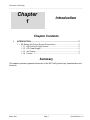
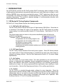
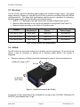
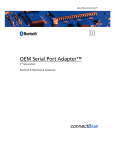
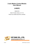
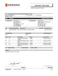
RX Series Products Phoseon FireFly™ User Manual March 2011 PN 26418 Rev. 1.0 © Phoseon Technology _____________________________________________________________________________________________________________________________ Phoseon FireFly™ - 4W SOLID STATE UV CURING SYSTEM USERS MANUAL PN: 26418 _________________________________________________________ All rights reserved. No part of this document may be stored in a retrieval system, transmitted, or used in any form or by any means, electronic, mechanical, photocopying, recording or otherwise without the prior permission of the copyright holder. Phoseon Technology, Inc. 7425 NW Evergreen Parkway Hillsboro, OR 97124-5845 USA For Technical Assistance Contact: Phone +1 503 439 6446 • Fax +1 503 439 6408 Email: [email protected] Home Page: www.phoseon.com Phoseon reserves the right to change specifications and other product information without notice. Product offered by Phoseon is covered by US Patent(s) and additional pending US and foreign patents. Phoseon™ is a registered trademark of Phoseon Technology. Copyright© 2011 Phoseon Technology _____________________________________________________________________________________________________________________________ March 2011 Page ii PN 26418 Rev. 1.0 © Phoseon Technology _____________________________________________________________________________________________________________________________ TABLE OF CONTENTS 1 INTRODUCTION ............................................................................................... 2 1.1 RX SERIES UV CURING SYSTEM COMPONENTS ............................................. 2 2 RX FIREFLY SAFETY ....................................................................................... 4 2.1 2.2 2.3 2.4 2.5 2.6 PROTECTIVE GUARDS................................................................................... 4 SAFETY NOTICES ......................................................................................... 5 UV SAFETY ................................................................................................. 6 INTEGRATION OF RX SERIES SYSTEM ............................................................ 7 RESTRICTION OF HAZARDOUS SUBSTANCES (ROHS) ...................................... 7 REGISTRATION, EVALUATION, AUTHORIZATION AND RESTRICTION OF CHEMICALS (REACH) .................................................................................................... 7 2.7 PRODUCT RECYCLING (WEEE)..................................................................... 7 3 SITE REQUIREMENTS ..................................................................................... 9 3.1 3.2 3.3 3.4 3.5 3.6 4 SETUP & OPERATION ................................................................................... 13 4.1 4.2 4.3 4.4 5 RX FIREFLY SETUP.................................................................................... 14 DC POWER/DATA CABLE CONNECTIONS FOR THE RX FIREFLY ..................... 22 REAR PANEL INDICATORS ........................................................................... 23 RX FIREFLY POWER SUPPLY SETUP ........................................................... 24 LIGHT SOURCE OPERATION ....................................................................... 28 5.1 5.2 5.3 5.4 5.5 6 FOOTPRINT .................................................................................................. 9 WEIGHT....................................................................................................... 9 ELECTRICAL ............................................................................................... 10 AIRFLOW ................................................................................................... 10 ENVIRONMENTAL ........................................................................................ 11 PLC CONTROL .......................................................................................... 11 ON/OFF CONTROL ..................................................................................... 28 IRRADIANCE VS. DISTANCE .......................................................................... 29 IRRADIANCE VS. TEMPERATURE ................................................................... 29 IRRADIANCE – TOTAL UV POWER ................................................................ 30 CONNECTING AN INTERLOCK ....................................................................... 30 SERVICE ......................................................................................................... 32 6.1 CLEANING GLASS ....................................................................................... 32 6.2 AIR FILTER REPLACEMENT .......................................................................... 32 6.3 RX FIREFLY – TROUBLESHOOTING GUIDE.................................................... 33 7 WARRANTY POLICY ..................................................................................... 35 7.1 WARRANTY POLICY .................................................................................... 35 7.2 PROCEDURE FOR WARRANTY CLAIMS .......................................................... 36 7.3 GENERAL PACKING INSTRUCTIONS .............................................................. 37 APPENDIX A ........................................................................................................... 39 _____________________________________________________________________________________________________________________________ March 2011 Page iii PN 26418 Rev. 1.0 © Phoseon Technology _____________________________________________________________________________________________________________________________ Revision History Revision 1.0 Nature of Change Initial Release Date March 2011 _____________________________________________________________________________________________________________________________ March 2011 Page iv PN 26418 Rev. 1.0 © Phoseon Technology _____________________________________________________________________________________________________________________________ Chapter 1 Introduction Chapter Contents 1 INTRODUCTION ............................................................................................... 2 1.1 RX SERIES UV CURING SYSTEM COMPONENTS ............................................. 2 1.1.1 RX FireFly UV Light Source ............................................................ 2 1.1.2 DC Power Supply............................................................................ 2 1.1.3 Air-Cooling ...................................................................................... 2 1.1.4 Control ............................................................................................ 2 Summary This chapter provides a general introduction of the RX FireFly and its key characteristics and functions. _____________________________________________________________________________________________________________________________ March 2011 Page 1 PN 26418 Rev. 1.0 © Phoseon Technology _____________________________________________________________________________________________________________________________ 1 INTRODUCTION Like all RX Series products the RX FireFly utilizes SLM™ technology which combines an array of light emitting semiconductor devices with high tech micro optics and micro cooling in a cost effective MOEMS (micro-opto-electro-mechanical system). SLM™ technology offers low cost of ownership, low energy consumption, increased productivity, long lifetime, as well as cooler operating temperature. The product’s physical package is environmentally attractive with mercury and ozone free operation. 1.1 RX Series UV Curing System Components RX FireFly UV Curing System requires the following components: 1.1.1 RX FireFly UV Light Source The RX FireFly emits a narrow band of pure UV light between 380-420nm. Since there is no emission in the deep UV region of the spectrum, the RX FireFly does not produce ozone making it an environmentally friendly UV Curing System. See Section 2.3 for UV safety. The product name which is shown on the product identification label will define the production configuration: Example: FireFly™ 25x20AC395-4W 25 represents the UV emitting length in mm 20 represents the UV emitting width in mm AC defines unit as air-cooled 395 defines wavelength in nm 4W defines the factory set peak irradiance up to 4W/cm² measured at the UV emitting window 1.1.2 DC Power Supply The RX FireFly utilizes standard off-the-shelf power supplies. Since RX Series products only require about 1/5 the electrical power of a traditional arc lamp; the power supply is compact and energy efficient. See the Site Requirements Section 3.3 for power supply specifications. 1.1.3 Air Cooling The RX FireFly is an air-cooled product. The heat generated by the semiconductor devices is dissipated with proprietary thermal management technology with no excess heat to the substrate. Since SLM™ technology produces 1/10 of the heat generated by traditional arc lamps; the cooling requirements are significantly lower resulting in lower cost of operation. See the Site Requirements Section 3.4 for airflow specifications. 1.1.4 Control The RX FireFly is controlled through simple voltages for easy integration. Since the semiconductor devices utilized in SLM™ technology can be turned on and off within a few milliseconds, there is no need for shutters and the Light Source can be enabled only when needed resulting in lower energy consumption and overall cost of operation. See the Setup Section 4.1.2 for PLC interface specifications. _____________________________________________________________________________________________________________________________ March 2011 Page 2 PN 26418 Rev. 1.0 © Phoseon Technology _____________________________________________________________________________________________________________________________ Chapter 2 Safety Chapter Contents 2 RX FIREFLY SAFETY ....................................................................................... 4 2.1 2.2 2.3 2.4 2.5 2.6 PROTECTIVE GUARDS................................................................................... 4 SAFETY NOTICES ......................................................................................... 5 UV SAFETY ................................................................................................. 6 INTEGRATION OF RX SERIES SYSTEM ............................................................ 7 RESTRICTION OF HAZARDOUS SUBSTANCES (ROHS) ...................................... 7 REGISTRATION, EVALUATION, AUTHORIZATION AND RESTRICTION OF CHEMICALS (REACH) .................................................................................................... 7 2.7 PRODUCT RECYCLING (WEEE)..................................................................... 7 Summary This chapter provides information regarding safe operation of the RX Series Light Source. _____________________________________________________________________________________________________________________________ March 2011 Page 3 PN 26418 Rev. 1.0 © Phoseon Technology _____________________________________________________________________________________________________________________________ 2 RX FireFly Safety It is important that you familiarize yourself with the safety features that are incorporated into the machine to provide a safe working environment. Similar to the ANSI Z535.4 standard, the ISO 3864-2 standard defines the hazard severity panels as follows: The yellow safety alert symbol indicates a possible human injury hazard exists. DANGER signal word used to indicate an imminently hazardous situation which, if not avoided, will result in death or serious injury. WARNING signal word used to indicate a potentially hazardous situation which, if not avoided, could result in death or serious injury. CAUTION signal word used to indicate a potentially hazardous situation which, if not avoided, could result in minor or moderate injury. 2.1 Protective Guards Phoseon Technology equipment is fitted with protective guards that fully enclose electrical mechanisms that may harm you or others during normal use. The fixed guards on Phoseon Technology equipment adhere to the appropriate international safety standards. Note: Do not operate the machine while any of the safety guards are open, loose, damaged or missing. _____________________________________________________________________________________________________________________________ March 2011 Page 4 PN 26418 Rev. 1.0 © Phoseon Technology _____________________________________________________________________________________________________________________________ 2.2 Safety Notices Symbol English description German description French description Spanish description Japanese description Safety Notices Sicherheitshinweise Consignes de Sécurite Notas de Seguridad 安全通知 Attention Read manual for safety instructions Vorsicht Bitte Vorsichtsmassnahmen in der Gebrauchsanleitung lesen Attention Lisez les instructions de sécurité dans le manuel Atención Lea el manual de Instrucciones de seguridad 注意 UV LICHT Vorsichtsmassnahmen in der Gebrauchsanleitung lesen Lumière UV Lisez les instructions de sécurité dans le manuel Luz UV Lea el manual de Instrucciones de seguridad Warnung UV STRAHLUNG RISIKOGROUPE 3 VON DIESEM PRODUKT EMITTIER Avertissement Rayonnement UV À Risque de Groupe 3 Advertencia RADIACION UV DE RIESDGO GRUPO 3 EMITIDA POR ESTE PRODUCTO UV Light Read manual for safety instructions Warning RISK GROUP 3 UV EMITTED FROM THIS PRODUCT Avoid eye and skin exposure to unshielded product. Vermeiden Augen und Haut Exposition von Produkt ohne ausreichenden Schutz. Évitez l'exposition d'oeil et de peau au produit non protégé. 安全上の注意のため のマニュアルを読み なさい 紫外線 安全上の注意のため のマニュアルを読み なさい 注意 LED線照射からの紫 外光にご注意下さい Evite la exposición de ojos y piel por el producto sin protección adecuada. 安全設備をちゃんと 設置してご使用下さ い 照射機からの紫外光 を直線に目視するこ とや皮膚に直接照ら すことをお控え下さ い。 Table 2-1 Safety Figure 2-1 RX FireFly Safety Label Placement _____________________________________________________________________________________________________________________________ March 2011 Page 5 PN 26418 Rev. 1.0 © Phoseon Technology _____________________________________________________________________________________________________________________________ 2.3 UV Safety Phoseon makes high-intensity solid-state ultraviolet (UV) Light Sources for industrial curing applications. These applications require high radiance and irradiance to initiate desired chemical reactions. CEI/IEC 62471 describes the photo-biological safety standards of lamps and LED systems. The actual source classification depends on usage, however, and when equipped with the proper interlocks and with limited viewing it is possible to make Phoseon sources safe for workers in the immediate vicinity. Hazard Classification: The classification scheme indicates only the potential risk. Depending upon use factors, time of exposure, and luminaire effects, these potential hazards may or may not actually become real hazards. Where the Light Source is intended for special applications, it should be evaluated and rated for the intended application. Distance specified in IEC 62471 for hazard classification is 200mm. Risk groups defined in IEC 62471 Exempt means there is no photo-biological hazard for the end points in this standard Risk Group 1 – Low Risk Does not pose a hazard due to normal behavioral limitations on exposure Risk Group 2 – Moderate Risk Does not pose a hazard due to aversion response to very bright Light Sources or due to thermal discomfort Note: A portion of the RX Series UV Light Source will be visible and will be a strong visual stimulus. Figure 2-2 Spectral Distribution Risk Group 3 – High Risk May pose a hazard even for momentary or brief exposure Phoseon’s Light Sources are classified as Risk Group 3 under IEC 62471 when viewed directly and close-up. However, when integrated into equipment, the risk is low to moderate or the Light Sources are exempt depending on specific integration schemes. Therefore, it is important that you do not look directly at the UV Light Source without wearing UV safety goggles. For example: UVEX SCT-orange lens which reduces eye fatigue by absorbing blue and green light and allows the operator to clearly view components during curing and inspection processes absorbs 99.9% of UV radiation and visible light up to 532nm. Note: RX Series products emit 90% or more of the total UV light energy between 380-420nm. As with all personal protective equipment, it is the employer's responsibility to conduct an onsite or workplace hazard assessment. _____________________________________________________________________________________________________________________________ March 2011 Page 6 PN 26418 Rev. 1.0 © Phoseon Technology _____________________________________________________________________________________________________________________________ 2.4 Integration of RX Series System RX Series systems are designed so that they can be professionally installed into a final product. It is the responsibility of the installer to ensure that the final product housing the RX Series components complies with the requirements of all applicable directives for the product. The RX Series Light Source and optional power supply, if purchased, is supplied as “open type” equipment. The RX Series system must be mounted within an enclosure that is suitably designed for the specific environmental conditions present for the final product, and appropriately designed to prevent personal injury resulting from accessibility to live parts. 2.5 Restriction of Hazardous Substances (RoHS) Phoseon Technology declares to the best of our knowledge, based on available information conducted to us, that the RX FireFly does not contain any homogeneous materials that: Contains lead (Pb) in excess of 0.1 weight -% (1000 ppm) Contains mercury (Hg) in excess of 0.1 weight-% (1000 ppm) Contains hexavalent chromium (Cr VI) in excess of 0.1 weight-% (1000 ppm) Contains polybrominated biphenyls (PBB) or polybrominated dimethyl ethers (PBDE) in excess of 0.1 weight-% (1000 ppm) Contains cadmium (Cd) in excess of 0.01 weight-% (100 ppm) 2.6 Registration, Evaluation, Authorization and Restriction of Chemicals (REACH) Phoseon Technology has determined that their products are not subject to EU REACH directive registration requirements. With regards to the projected candidate list of substances of very high concern (SVHC) – issued 10 October 2008. Phoseon Technology further declares that, to the best of our knowledge, our products do not contain any currently listed SVHC above the level 0.1% by weight. 2.7 Product Recycling (WEEE) This symbol is an internationally agreed indicator that the product bearing it should not be disposed of as general waste or garbage which might end up in landfill sites, but should instead be returned to Phoseon for reuse or be disposed of in accordance with local laws. Figure 2-3 Do Not Recycle Symbol _____________________________________________________________________________________________________________________________ March 2011 Page 7 PN 26418 Rev. 1.0 © Phoseon Technology _____________________________________________________________________________________________________________________________ Chapter 3 Site Requirements Chapter Contents 3 SITE REQUIREMENTS ..................................................................................... 9 3.1 FOOTPRINT .................................................................................................. 9 3.1.1 Light Source Dimensions ................................................................ 9 3.1.2 Optional Power Supply Dimensions ................................................ 9 3.2 WEIGHT....................................................................................................... 9 3.2.1 RX FireFly ....................................................................................... 9 3.2.2 Optional Power Supply ................................................................... 9 3.3 ELECTRICAL ............................................................................................... 10 3.4 AIRFLOW ................................................................................................... 10 3.5 ENVIRONMENTAL ........................................................................................ 11 3.5.1 Light Source .................................................................................. 11 3.5.2 Optional Power Supply ................................................................. 11 3.6 PLC CONTROL .......................................................................................... 11 Summary This chapter provides an overview of the site requirements for integrating an RX FireFly UV Light System. _____________________________________________________________________________________________________________________________ March 2011 Page 8 PN 26418 Rev. 1.0 © Phoseon Technology _____________________________________________________________________________________________________________________________ 3 Site Requirements 3.1 Footprint 3.1.1 Light Source Dimensions RX FireFly Length (mm) Width (mm) Height (mm) Size 110 68 200 Table 3-1 Light Source Dimensions 3.1.2 Optional Power Supply Dimensions Power Supply Length (mm) Width (mm) Height (mm) SDR-480-48 86 125 129 Table 3-2 Power Supply Dimensions 3.2 Weight 3.2.1 RX FireFly RX FireFly: 1 kg (2.2 lbs) 3.2.2 Optional Power Supply 480W: 1.6 kg (3.5 lbs) _____________________________________________________________________________________________________________________________ March 2011 Page 9 PN 26418 Rev. 1.0 © Phoseon Technology _____________________________________________________________________________________________________________________________ 3.3 Electrical The RX FireFly requires a switching power supply with constant voltage output. The power supply tested by Phoseon for use with the RX FireFly systems is the Mean Well SDR-480-48 (see Appendix A). The Mean Well specifications can be used as a guideline for selecting a switching power supply with the following critical specifications: 48VDC +/- 1V delivered to the Light Source from constant voltage output source Minimum Watts delivered to the Light Source based on configuration (see Table 3-3) Maximum ripple should be on the order of 4V peak-to-peak Product Power Requirement Voltage at the Light Source Optional Mean Well Power Supply RX FireFly 75x20 Up to 480W +48±1VDC SDR-480-48 RX FireFly 50x20 Up to 336W +48±1VDC SDR-480-48 RX FireFly 25x20 Up to 192W +48±1VDC SDR-480-48 Table 3-3 RX FireFly Power Requirements 3.4 Airflow The RX FireFly has an internal cooling fan to properly cool the components. Do not restrict the airflow, it may be necessary to exhaust air to maintain proper airflow if the system is integrated. Minimum clearance of 50mm should be maintained for main air inlet and exhaust ports Ambient Air Temp < 40°C Air Inlet Air Exhaust (both sides) Figure 3-1 Airflow direction for RX FireFly An optional air filter replacement is also available for the top air inlet, PN 25981, Multicomp PN MC32707, polyurethane foam, 45 ppi. _____________________________________________________________________________________________________________________________ March 2011 Page 10 PN 26418 Rev. 1.0 © Phoseon Technology _____________________________________________________________________________________________________________________________ 3.5 Environmental 3.5.1 Light Source Light Source Operating Environment Operation Altitude Operating Temp (°C) Storage (°C) Humidity RH non-condensing for temperatures up to 30°C RX FireFly Indoor Use Only Up to 3000m* 0 to 40 -20 to 85 20 to 95% Table 3-4 RX FireFly Environmental Specifications * Power supply selected for integration should be consistent with intended altitude requirements. This instrument has been designed for use in harsher industrial manufacturing environments with pollution degree 3. 3.5.2 Optional Power Supply If using the optional Mean Well power supply, environmental specifications are shown below. Please refer to Appendix A for additional Mean Well power supply specifications. Power Supply Model Description Operating Environment Operating Altitude Operating Temp (°C) Storage (°C) Humidity RH non-condensing Cooling SDR-480-48 480W Indoor Use Only Up to 2000m* -25 to 70** -40 to 85 20 to 95% Forced air Table 3-5 RX FireFly Optional Power Supply Environmental Specifications * Note the power supply rated altitude is lower than the Light Source ** When operated above 70°C, see de-rating curve in Appendix Power supply pollution degree rating should be consistent with end user’s environmental conditions. 3.6 PLC Control The Light Source can be controlled via a PLC (Programmable Logic Controller) using the 13W3 connector. For more information please refer to section 4.1.2 of this manual. _____________________________________________________________________________________________________________________________ March 2011 Page 11 PN 26418 Rev. 1.0 © Phoseon Technology _____________________________________________________________________________________________________________________________ Chapter 4 Light Source Setup Chapter Contents 4 SETUP & OPERATION ................................................................................... 13 4.1 RX FIREFLY SETUP.................................................................................... 14 4.1.1 Mounting: ...................................................................................... 14 4.1.2 PLC Interface ................................................................................ 15 4.1.3 Light Source Setup Scenarios ...................................................... 19 4.2 DC POWER/DATA CABLE CONNECTIONS FOR THE RX FIREFLY ..................... 22 4.3 REAR PANEL INDICATORS ........................................................................... 23 4.4 RX FIREFLY POWER SUPPLY SETUP ........................................................... 24 4.4.1 Example Installation of Power Supply ........................................... 24 Summary This chapter of the manual will cover the steps required to setup the RX FireFly UV Light System. _____________________________________________________________________________________________________________________________ March 2011 Page 12 PN 26418 Rev. 1.0 © Phoseon Technology _____________________________________________________________________________________________________________________________ 4 Setup & Operation The diagram below shows an overview of the components that will need to be setup for proper operation of the RX FireFly UV Light Source System. Data/DC Power Cable Mating connector FCI PN: DB013W3SA00LF (Housing), 8638PSS1505LF (15A Max Female Contacts, solder or 8638PSC2005LF 20A Max Female, crimp) Type: 13W3 Female (socket) Dsub connector* (See Section 4.2) Ambient Air: <40C Air Inlet (top): Data & DC Power Connector Type 13W3: Input Power: 481VDC Minimum Clearance: 50mm (See Site Requirements Section 3.4) RX FireFly 50x20: Power Consumption: up to 324W RX FireFly 25x20: Power Consumption: up to 162W (See Section 4.1.2) Optional ¼-20 Mounting (See Section 4.1.1) RX FireFly Mounting 4X M3x0.5 Mounting Positions (See Section 4.1.1) Air Exhaust (both sides) Minimum Clearance: 50mm (See Site Requirements Section 3.4) Figure 4-1 Diagram for RX FireFly System Setup *Components shown with purple outline are options that are sold separately and are available from Phoseon. _____________________________________________________________________________________________________________________________ March 2011 Page 13 PN 26418 Rev. 1.0 © Phoseon Technology _____________________________________________________________________________________________________________________________ 4.1 RX FireFly Setup An overview of the steps required to setup the RX FireFly UV Light System are shown below with detailed instructions for each step in the following sub-sections: 4.1.1 4.1.2 4.1.3 4.1.1 Mounting PLC/Power Interface Light Source Setup Scenarios Mounting: The RX FireFly can be mounted using the mounting holes located on the back of the unit as shown in the diagram below: 4X M3x0.5 Mounting Positions Optional ¼-20 Mounting Figure 4-2 RX FireFly Mounting Holes In order to assist users with process development, Phoseon offers an optional RX FireFly adjustable arm as shown below. The RX FireFly has a standard ¼-20 mounting hole as shown in the functional layout diagram (Figure 4-4) for ease of mounting with standard camera connections or optical bench. Figure 4-3 RX FireFly Adjustable Arm Option _____________________________________________________________________________________________________________________________ March 2011 Page 14 PN 26418 Rev. 1.0 © Phoseon Technology _____________________________________________________________________________________________________________________________ Figure 4-4 Design Layout of the RX FireFly-4W 4.1.2 PLC Interface The DB13W3 connector is used to control the Light Source via a PLC and also provides power to the Light Source. The connector, as shown below is numbered with Pins 1-5 on the top row (right to left) and Pins 6-10 on the bottom row (right to left). Figure 4-5 shows the pin numbering on the RX FireFly connector and Table 4-1 shows the connector pin assignments. Figure 4-5 DB13W3 Connector Pin Number Diagram Note: All input and output control signals; i.e. voltages, from the Light Source, must be referenced to the same common Ground as the 48VDC input power. _____________________________________________________________________________________________________________________________ March 2011 Page 15 PN 26418 Rev. 1.0 © Phoseon Technology _____________________________________________________________________________________________________________________________ There is a connector located on the side of the RX FireFly, as shown below, that is for factory use ONLY. DO NOT connect to this connector. Figure 4-6 RX FireFly Factory Use Only Connector _____________________________________________________________________________________________________________________________ March 2011 Page 16 PN 26418 Rev. 1.0 © Phoseon Technology _____________________________________________________________________________________________________________________________ The 13W3 connector on the RX FireFly has the following interface: Pin Function 1 Do Not Use 2 INTENSITY CONTROL (Option 1) Input/ Output --- Range (min/max) --- I 0.0V to +5.0V Comments Do Not Use Input voltage is converted to required current to achieve desired intensity where 5V = 100% and 1.0V = 20%. A minimum voltage of 1.0V is required for proper Light Source operation. Note: Connect to Pin 6 for 100% Intensity (Zin = 10kΩ) 3 ENABLE HIGH 4 INTENSITY CONTROL (Option 2) I 0.0V or +5.0V I 0.0V to +10.0V TTL (transistor-transistor logic) Input: 0.0V to +0.4V = OFF (Open input will default to OFF) +3.5V to +5.0V = ON RX FireFly behavior if operated outside these specified voltages is not definite. Input voltage is converted to required current to achieve desired intensity where 10V = 100% and 2.0V = 20%. A minimum voltage of 2.0V is required for proper light source operation. (Zin = 10kΩ) 5 THERMAL FAULT O 0.0V or +5.0V 6 Do Not Use --- --- 7 INTERLOCK I 0.0V or +5.0V 8, 10 Ground --- 0.0V 9 TEMPERATURE MONITOR O 0.0V to +10.5V A1 +48VDC Power Input I A2 A3 Ground PE ----- +47V to +49V 0.0V 0.0V Open Collector TTL Output / TTL Input: 0.0V to +0.4V (Ground) = Fault +3.5V to +5.0V (open) = No Fault Sink Current Maximum = 5mA RX FireFly behavior if operated outside these specified voltages is not definite. Note: See Figure 4-7 for more details DO NOT USE; Except to connect directly to Pin 2 for 100% Intensity For use with external customer defined interlock circuit, if no interlock is present, defeat this feature by connecting one of the Ground pins to Pin 7 If interlock circuit is present, connect interlock to Pin 7 only. TTL (transistor-transistor logic) Input: 0.0V to +0.4V = UV Emission Allowed +3.5V to +5.0V = UV Emission Stopped RX FireFly behavior if operated outside these specified voltages is not definite. Note: Connect to Ground pin (Pin 8 or 10) if no interlock is used Refer to Operation Section 5.5 for implementation details Ground Output is a voltage proportional to SLM heat sink temperature This value should not exceed approximately +8V Conversion Factor: 0.1V/˚C (Example 30˚C = 3.0V) +48VDC Power Input to power Light Source +48VDC Return, Ground Protective Earth, Ground Table 4-1 Pin Connections for the 13W3 Connector _____________________________________________________________________________________________________________________________ March 2011 Page 17 PN 26418 Rev. 1.0 © Phoseon Technology _____________________________________________________________________________________________________________________________ The diagram below illustrates the circuitry involved if a fault should occur (pin 5). Figure 4-7 Fault (Open Collector Output) Diagram _____________________________________________________________________________________________________________________________ March 2011 Page 18 PN 26418 Rev. 1.0 © Phoseon Technology _____________________________________________________________________________________________________________________________ 4.1.3 Light Source Setup Scenarios Setup Scenario #1 – On/Off at 100% Intensity No PLC – Simple On/Off Switch 100% Intensity Only No Fault or Temperature Monitoring No External Interlock Figure 4-8 Light Source Setup Scenario #1 _____________________________________________________________________________________________________________________________ March 2011 Page 19 PN 26418 Rev. 1.0 © Phoseon Technology _____________________________________________________________________________________________________________________________ Setup Scenario #2 – On/Off with Intensity Control using PLC PLC Control Intensity Control 1-5V for 20-100% UV Output Temperature Monitoring No Fault Monitoring No External Interlock Figure 4-9 Light Source Setup Scenario #2 _____________________________________________________________________________________________________________________________ March 2011 Page 20 PN 26418 Rev. 1.0 © Phoseon Technology _____________________________________________________________________________________________________________________________ Setup Scenario #3 – On/Off with Intensity Control and feedback using PLC PLC Control Intensity Control 1-5V for 20-100% UV Output Temperature Monitoring Thermal and SLM Fault Monitoring External Interlock Figure 4-10 Light Source Setup Scenario #3 _____________________________________________________________________________________________________________________________ March 2011 Page 21 PN 26418 Rev. 1.0 © Phoseon Technology _____________________________________________________________________________________________________________________________ 4.2 DC Power/Data Cable Connections for the RX FireFly The RX FireFly-4W Light Sources are connected to the power supply through a 13W3 type connector where Pins A1-A3 are for DC power input and pins 1-10 are for light source control through a PLC. +48VDC Return +48VDC To Power Supply: +48VDC (Pin A1) +48VDC Return (Pin A2) Figure 4-11 RX FireFly DC Connector and Cable The mating DB13W3 connector is a 13W3 Female (socket) Dsub connector. FCI part numbers for the connector assembly are as follows: DB13W3SA00LF (Housing), 8638PSS1505LF (15A Max Female Contacts) and 8655MH2501LF (connector back shell). If the DC Power/Data Y cable is purchased from Phoseon, the pin diagram of the DB15 is as follows: Pin Function 1 Do Not Use INTENSITY CONTROL (Option 1) 2 Input/ Output --- Range (min/max) --- I 0.0V to +5.0V See Pin 2 on 13W3 Connector, Table 4-1Table 4-1 Comments Do Not Use 3 ENABLE HIGH I 0.0V or +5.0V See Pin 3 on 13W3 Connector, Table 4-1 4 INTENSITY CONTROL (Option 2) I 0.0V to +10.0V See Pin 4 on 13W3 Connector, Table 4-1 5 THERMAL FAULT O 0.0V or +5.0V See Pin 5 on 13W3 Connector, Table 4-1 6 Do Not Use --- --- See Pin 6 on 13W3 Connector, Table 4-1 7 INTERLOCK I 0.0V or +5.0V See Pin 7 on 13W3 Connector, Table 4-1 8, 10, 14 Ground --- 0.0V 9, 11-13 Do Not Use --- --- 15 TEMPERATURE MONITOR O 0.0V to +10.5V Ground Do Not Use See Pin 9 on 13W3 Connector, Table 4-1 Table 4-2 DC Power/Data Y cable DB15 Pin Diagram _____________________________________________________________________________________________________________________________ March 2011 Page 22 PN 26418 Rev. 1.0 © Phoseon Technology _____________________________________________________________________________________________________________________________ 4.3 Rear Panel Indicators The RX FireFly is designed with an indicator to tell the user when the unit is plugged in and UV Light Source is enabled. Blue LED indicates UV ON Green LED indicates DC power present Figure 4-12 RX FireFly Indicator Lights _____________________________________________________________________________________________________________________________ March 2011 Page 23 PN 26418 Rev. 1.0 © Phoseon Technology _____________________________________________________________________________________________________________________________ 4.4 RX FireFly Power Supply Setup As noted in Section 2.4, the RX Series Light Source and optional power supply if purchased is supplied as “open type” industrial equipment and is intended for installation within enclosures supplied in the field. It must be mounted within an enclosure that is suitably designed for those specific environmental conditions that will be present, and appropriately designed to prevent personal injury resulting from accessibility to live parts. Warning: Only trained, qualified installers and service mechanics should install, start-up, and service this equipment. An example power supply system setup using the Mean Well power supply is shown for illustrative purposes. Because of the many variables and requirements associated with any particular installation, Phoseon Technology cannot assume responsibility or liability for actual use based on the examples and diagrams. Note: If supplying your own power supply, please ensure it meets the specifications in the Site Requirements Section 3.3. 4.4.1 Example Installation of Power Supply The power supply used in this example has been functionally tested for use with Phoseon’s RX Series products. Specific product specifications for this power supply are provided in Appendix A for convenience. This example will cover the following: 4.4.1.1 4.4.1.2 4.4.1.3 4.4.1.4 Mounting AC Power Cable Connection DC Power Cable Connection Verify DC Voltage 4.4.1.1 Mounting Mean Well Power Supply Mount the power supply in a position where both the AC and DC power cords will not be stressed and airflow to the power supply will not be impeded. Mounting information for the 480W power supply from Mean Well is provided by the vendor and shown in Appendix A. The dimensioned drawing is copied here for reference. _____________________________________________________________________________________________________________________________ March 2011 Page 24 PN 26418 Rev. 1.0 © Phoseon Technology _____________________________________________________________________________________________________________________________ SDR-480-48 Figure 4-13 RX FireFly 480W Optional Power Supply Dimensions 4.4.1.2 Connecting AC Power Cable to Mean Well Power Supply Connect the AC power cable to the power supply by connecting the AC power cord to the AC/L, AC/N, and Ground pins as shown in the example below. Figure 4-14 Power Supply AC Connection Warning: Do not connect or disconnect the AC Power Line to the Terminal Strip with power applied. _____________________________________________________________________________________________________________________________ March 2011 Page 25 PN 26418 Rev. 1.0 © Phoseon Technology _____________________________________________________________________________________________________________________________ 4.4.1.3 Connecting DC Power Cable to Mean Well Power Supply The DC Power Cable connects the RX FireFly light source to the power supply. Connect the DC Cable to the power supply connecting the ferrule (either black ferrule or black wire) to DC output V- terminals and ferrule (either red ferrule or red wire) to DC Output V+ terminals, and the protective earth ground to the power supply chassis, as shown in the example below. Figure 4-15 Power Supply DC Connections Note: Do not connect or disconnect the DC cable harness to the Light Source while power is applied. 4.4.1.4 Verify DC Voltage for Mean Well Power Supply Check the voltage output of the power supply and verify it is set correctly (+48VDC measured at the Light Source). Adjust if necessary. If using the optional Mean Well power supply, the voltage can be adjusted using the potentiometer shown below. Voltage Adjustment Potentiometer Figure 4-16 Voltage Adjustment for the Optional 480W Power Supply _____________________________________________________________________________________________________________________________ March 2011 Page 26 PN 26418 Rev. 1.0 © Phoseon Technology _____________________________________________________________________________________________________________________________ Chapter 5 Light Source Operation Chapter Contents 5 LIGHT SOURCE OPERATION ....................................................................... 28 5.1 5.2 5.3 5.4 ON/OFF CONTROL ..................................................................................... 28 IRRADIANCE VS. DISTANCE .......................................................................... 29 IRRADIANCE – TOTAL UV POWER ................................................................ 29 CONNECTING AN INTERLOCK ....................................................................... 30 Summary This chapter of the manual will cover the steps required to operate the RX FireFly UV Light Source. _____________________________________________________________________________________________________________________________ March 2011 Page 27 PN 26418 Rev. 1.0 © Phoseon Technology _____________________________________________________________________________________________________________________________ 5 Light Source Operation This section describes tips for operating the Light Source when integrated into equipment and covers the following: 5.1 5.2 5.3 5.5 On/Off Control Irradiance vs. Distance Irradiance – Total UV Power Connecting an Interlock 5.1 On/Off Control The RX FireFly is controlled through simple voltages. Since the semiconductor devices utilized in SLMTM technology can be turned on and off in less than 5ms, there is no need for shutters and the Light Source can be enabled only when needed. RX FireFly can be turned on/off through the PLC enable circuitry at Pin 2; see Section 4.1.2. Figure 5-1 Instant On/Off Note: When the Light Source is not needed (when not actively curing), turn off the Light Source to avoid the build-up of heat. Even if the surface of the Light Source is not heating up, the area around the Light Source (for example - any material held in close proximity to the emitting window without moving and surrounding air) can reach very high temperatures. _____________________________________________________________________________________________________________________________ March 2011 Page 28 PN 26418 Rev. 1.0 © Phoseon Technology _____________________________________________________________________________________________________________________________ 5.2 Irradiance vs. Distance Phoseon RX Series Light Sources use optics to capture and direct the light to the work surface, but unlike arc lamps, Phoseon’s Light Sources are area sources. Therefore, the optimum placement for the highest intensity will be closest to the UV emitting window. A typical distance from the RX FireFly to the substrate is 3-5mm. Phoseon does not use reflectors that require positioning the Light Source several inches away from the material. The UV light from the emitting window of the RX FireFly does diverge with distance, so the peak irradiance will decrease as a function of distance from the protective glass. Figure 5-2 Irradiance as a Function of Distance 5.3 Irradiance vs. Temperature The performance of the RX FireFly, which is an air cooled system, will be directly impacted by the temperature of the ambient air. Irradiance will decrease slightly as the ambient air increases. A temperature switch has been integrated into the light source to shut down the emission of UV light when the light source has exceeded a safe operating temperature. The light source will shut off to prevent a thermal run away condition and a Thermal Fault signal will be output (Pin 5) see Figure 4-1. Note: When a temperature fault occurs, the light source will shut off automatically. The light source will turn back on automatically when the operating temperature has returned to an acceptable value. Do not exceed the air temperature specifications as indicated in the site requirements Section 3.5.1. _____________________________________________________________________________________________________________________________ March 2011 Page 29 PN 26418 Rev. 1.0 © Phoseon Technology _____________________________________________________________________________________________________________________________ 5.4 Irradiance – Total UV Power Phoseon’s RX Series products utilizing SLMTM technology deliver high peak irradiance over a large area generating the highest total UV Power. The total UV power produced by the RX FireFly is a function of the area of the emitting window and peak irradiance. An RX FireFly 395nm system will output up to 60W of UV Power between the wavelength range of 380420nm. 5.5 Connecting an Interlock The RX FireFly has the capability to support a customer supplied interlock circuit. This is useful for situations where the function of the Light Source is tied to an enclosure or distance above a conveyor, where the UV emission should be stopped when a door is opened or if the Light Source is raised a specified distance above a conveyor. An external interlock circuit is not required for Light Source operation. If no interlock is present, simply connect Pin 7 to any Ground pin (Pin 8 or 10) to disable this feature. _____________________________________________________________________________________________________________________________ March 2011 Page 30 PN 26418 Rev. 1.0 © Phoseon Technology _____________________________________________________________________________________________________________________________ Chapter 6 Service Chapter Contents 6 SERVICE ......................................................................................................... 32 6.1 CLEANING GLASS ....................................................................................... 32 6.2 AIR FILTER REPLACEMENT .......................................................................... 32 6.3 RX FIREFLY – TROUBLESHOOTING GUIDE.................................................... 33 Summary This chapter describes service items associated with the RX FireFly Light Source _____________________________________________________________________________________________________________________________ March 2011 Page 31 PN 26418 Rev. 1.0 © Phoseon Technology _____________________________________________________________________________________________________________________________ 6 Service For further details contact Phoseon Technology by phone at +1.503.439.6446 or email at [email protected] 6.1 Cleaning Glass The emitter glass on the light source should be cleaned on an as needed basis. For light cleaning please use general purpose glass cleaner or Isopropyl Alcohol and a soft cloth. DO NOT submerge the light source or spray cleaning solution directly onto the light source. If the material cannot be removed with glass cleaner or Isopropyl Alcohol, then a ceramic utility scraper (similar to the one shown below) can be used to carefully scrape the material off of the glass. Figure 6-1 - Ceramic Utility Scraper for Glass Cleaning Please note, it is the employer’s responsibility to provide proper PPE (personal protective equipment) when working with hazardous chemicals or sharp equipment. 6.2 Air Filter Replacement Clean the fan filter on an as-needed basis. The time interval will vary depending on the environment where the unit is installed. 1. Turn off the power to the Light Source and disconnect the power cord. 2. Remove the retainer and filter (no tools required) and soak the filter in hot soapy water. Note: Do not use abrasive scouring powders to clean the air filter. Never spray liquid into the fan filter while installed on the Light Source. 3. If needed, wipe the fan guard and retainer down with dry paper towels. 4. After drying the filter, place it back into the fan guard and secure the filter in place with the retainer. 5. Reconnect main power cord. 6. The Light Source can then be powered on. _____________________________________________________________________________________________________________________________ March 2011 Page 32 PN 26418 Rev. 1.0 © Phoseon Technology _____________________________________________________________________________________________________________________________ 6.3 RX FireFly – Troubleshooting Guide Symptom Component Power Supply No Light is emitted from Light Source Light Source with PLC Control Over-temp Action or Cause Check that AC and DC cables are wired correctly to power supply: - See Appendix A in User Manual - Check that power supply is plugged in to AC outlet and turned on Check wiring to DB13W3 connector (see Table 4-1) - Green light on - Pin 7 (interlock) must be tied to Ground (Pin 8 or 10) If Light Source has thermally tripped, no light will be emitted until the Light Source returns to a safe operating temperature (see Airflow Section 3.4). Note that the fans will continue to operate if the Light Source has thermally tripped. Table 6-1 Troubleshooting Guide _____________________________________________________________________________________________________________________________ March 2011 Page 33 PN 26418 Rev. 1.0 © Phoseon Technology _____________________________________________________________________________________________________________________________ Chapter 7 Warranty Policy Chapter Contents 7 WARRANTY POLICY ..................................................................................... 35 7.1 WARRANTY POLICY: ................................................................................... 35 7.2 PROCEDURE FOR WARRANTY CLAIMS: ......................................................... 36 7.3 GENERAL PACKING INSTRUCTIONS: ............................................................. 37 Summary Phoseon Technology warranties our product under normal use. See Warranty Policy for further details. _____________________________________________________________________________________________________________________________ March 2011 Page 34 PN 26418 Rev. 1.0 © Phoseon Technology _____________________________________________________________________________________________________________________________ 7 Warranty Policy 7.1 Warranty Policy Thank you for purchasing a quality Phoseon Technology product. Supplier warrants that all equipment shall be free from defects in material and workmanship if properly installed, stored, maintained and operated by Buyer under normal use with competent supervision for a period of one (1) year from date of shipment to Buyer (see Terms & Conditions for full warranty specifications). Phoseon Technology will repair or replace, at its option, any defective parts when returned freight pre-paid by Buyer to Phoseon. Equipment damaged in transit, abused, misused, operated on incorrect power sources, or on which the factory seals have been broken (evidencing unauthorized intrusion), shall be excluded from warranty coverage. Determination of the suitability of the product or fitness to a particular purpose lies solely with the Buyer. Phoseon assumes no liability for any incidental or consequential damages or expense. Equipment may not be returned, whether for warranty or other purposes, without prior authorization and issuance of a Returned Material Authorization Number by Phoseon Technology. Phoseon Technology assumes no expense or liability for repairs made outside its facility without written consent or for any labor costs which are incurred. If repair of equipment is required but return of such equipment to Phoseon Technology is not feasible, then by mutual consent of Phoseon and purchaser, an authorized Phoseon service representative will be sent to the purchaser’s plant to effect necessary repairs. The purchaser will be charged for the representative’s time and expenses. Any repairs or alternations, including use of non-Phoseon parts, made by the user of this product without Phoseon’s prior written consent shall void all warranties provided by Phoseon Technology and such warranties shall cease to be in effect. No allowance will be granted for such repairs or alterations. No person, agent, representative, or distributor is authorized to give any warranties on behalf of Phoseon Technology, or to accept for Phoseon Technology any other liability in connection with any Phoseon products. This warranty excludes consumables such as fuses without regard to whether any claimed defects were discoverable or latent on the date of shipment. The following are the standard product specifications unless otherwise agreed upon: Measurements to be taken at the output of the protective glass while operating continuously (maximum (peak) over output area): RX FireLine: 125, 150, 225, 300 - 8W/cm2 RX FireFly: 1.5W/cm2 - 4W/cm2 RX StarFire MAX: 75, 150, 300 - 4W/cm2 RX StarFire: 100 - 2W/cm2 RX StarFire: 150 - 1.75W/cm2 RX FireFlex: 75 - 8W/cm2 RX FireJet: 225 - 7W/cm² _____________________________________________________________________________________________________________________________ March 2011 Page 35 PN 26418 Rev. 1.0 © Phoseon Technology _____________________________________________________________________________________________________________________________ Note: If the equipment is used in a manner not specified by the manufacturer, the protection provided by the equipment may be impaired. If the equipment is not used in a manner as explicitly stated in the manual, then this shall be deemed to be misuse and will invalidate any warranty claim. 7.2 Procedure for Warranty Claims 1. Obtain RMA Number from Phoseon Technology. Equipment may not be returned, whether for warranty or other purposes, without prior authorization and issuance by Phoseon Technology of a Returned Material Authorization Number. Please call +1.503.439.6446 or send email to [email protected] to request an RMA number. Serial number of unit is required. 2. All Products being returned for warranty repair must be sent back to Phoseon Technology in original or comparable packaging (see below). Phoseon Technology shall not be responsible for items being exchanged that are lost or damaged in transit. Postage and handling charges both to and from Phoseon Technology must be paid the customer. We strongly recommend that you FULLY INSURE THE PACKAGE. 3. Phoseon will inspect non-functioning product to determine cause of failure. Loss of or damage to the covered product due to abuse, mishandling, improper packaging by you, alteration, accident, electrical current fluctuations or failure to follow operating, maintenance or environmental instructions prescribed in the covered product's User Manual is subject to a fee. 4. Replacement components are functionally tested before shipping. 5. A new or refurbished component, at Phoseon Technology’s sole discretion, will be sent to the customer at the customer’s expense. 6. Replacement components will be covered by the balance of the time remaining on the customer's original limited warranty or 90 days whichever is longer (unless otherwise specified). _____________________________________________________________________________________________________________________________ March 2011 Page 36 PN 26418 Rev. 1.0 © Phoseon Technology _____________________________________________________________________________________________________________________________ 7.3 General Packing Instructions If possible, original packaging materials should be reused for return shipment to Phoseon Technology. If Phoseon Technology’s packaging materials are not used, equivalent packaging, as outlined in the following sections, is to be used. Power Supply: Box: Bursting Test: 24kg/cm2 (350lbs/sq in) Gross Weight Limit: 70kg (155lbs) Fills: Rigid high density Styrofoam or cardboard fills as required to ensure power supply does not shift in box during shipment. Note: Packaging materials should not push against connectors or controls. RX Series UV Light Source: Box: Bursting Test: 24kg/cm2 (350lbs/sq in) Gross Weight Limit: 70kg (155lbs) Fills: Rigid high density Styrofoam as required ensuring power supply does not shift in box during shipment. Note: Packaging materials should not push against glass or connectors or controls. _____________________________________________________________________________________________________________________________ March 2011 Page 37 PN 26418 Rev. 1.0 © Phoseon Technology _____________________________________________________________________________________________________________________________ Appendix Appendix Contents APPENDIX A ........................................................................................................... 39 Summary The appendix provide data specifications to related items of the RX FireFly _____________________________________________________________________________________________________________________________ March 2011 Page 38 PN 26418 Rev. 1.0 © Phoseon Technology _____________________________________________________________________________________________________________________________ Appendix A Mean Well USA Model SDR-480-48 _____________________________________________________________________________________________________________________________ March 2011 Page 39 PN 26418 Rev. 1.0 © Phoseon Technology _____________________________________________________________________________________________________________________________ _____________________________________________________________________________________________________________________________ March 2011 Page 40 PN 26418 Rev. 1.0 © Phoseon Technology _____________________________________________________________________________________________________________________________ _____________________________________________________________________________________________________________________________ March 2011 Page 41 PN 26418 Rev. 1.0