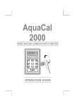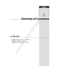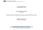
1
SGI® UVTM System Management Node
Administrator Guide
007–5694–010
COPYRIGHT
© 2010–2013 SGI. All rights reserved; provided portions may be copyright in third parties, as indicated elsewhere herein. No
permission is granted to copy, distribute, or create derivative works from the contents of this electronic documentation in any manner,
in whole or in part, without the prior written permission of SGI.
LIMITED RIGHTS LEGEND
The software described in this document is "commercial computer software" provided with restricted rights (except as to included
open/free source) as specified in the FAR 52.227-19 and/or the DFAR 227.7202, or successive sections. Use beyond license provisions is
a violation of worldwide intellectual property laws, treaties and conventions. This document is provided with limited rights as defined
in 52.227-14.
TRADEMARKS AND ATTRIBUTIONS
Altix, SGI, the SGI logo, and UV are are trademarks or registered trademarks of Silicon Graphics International Corp. or its subsidiaries
in the United States and other countries.
Firefox and Mozilla are registered trademarks of the Mozilla Foundation. Linux is a registered trademark of Linus Torvalds in the
United States and other countries. Microsoft and Windows are registered trademarks or trademarks of Microsoft Corporation in the
United States and/or other countries. Novell and SUSE are registered trademarks of Novell, Inc., in the United States and other
countries. Red Hat and all Red Hat-based trademarks are trademarks or registered trademarks of Red Hat, Inc. in the United States
and other countries. SUPERMICRO is a registerd trademark of Super Micro Computer, Inc. All other trademarks mentioned herein are
the property of their respective owners.
New Features in This Manual
This rewrite of the SGI UV System Management Node Administrator Guide supports the
SGI System Management Node 1.7 release.
The installation and configuration information that used to reside in this manual has
been updated and removed to the SGI UV Systems Software Installation Guide. The SGI
UV Systems Software Installation Guide contains information about how to install and
configure operating system software, SGI Foundation Software, and System
Management Node (SMN) software on the SMN and on the SGI UV server.
Information about SMN commands has been rewritten.
An appendix section that includes information about network topology on SGI UV
2000 and SGI UV 1000 systems has been added.
007–5694–010
iii
Record of Revision
007–5694–010
Version
Description
001
October 2010
Original Printing.
002
February 2011
Updated to support the SGI Foundation Software 2.3 release.
003
February 2011
Updated to support additional changes for the SGI Foundation
Software 2.3 release.
004
February 2011
Updated to add information about remote console and reinstalling
operating system software.
005
March 2011
Updated to support additional changes for the SGI Foundation
Software 2.3 release.
006
April 2011
Updated to support changes for the SGI Foundation Software 2.4
release.
007
July 2011
Updated to support additional changes for the SGI Foundation
Software 2.4 release.
008
September 2011
Updated to support additional changes for the SGI Foundation
Software 2.4 release.
009
May 2012
Updated to support changes for the SGI System Management Node
1.5 release.
010
May 2013
Updated to support the SGI System Management Node 1.7 release.
v
Contents
About This Manual
Obtaining Publications
. . .
.
.
.
.
. . . .
.
.
Related Publications and Other Sources
Conventions
.
.
Reader Comments
. . .
. . . .
. . . .
. .
ix
.
.
.
.
.
.
.
.
.
.
.
.
.
.
.
.
ix
.
.
.
.
.
.
.
.
.
.
.
.
.
.
.
.
ix
.
.
.
.
.
.
.
.
.
.
.
.
.
.
.
.
.
.
.
.
.
.
.
x
.
.
.
.
.
.
.
.
.
.
.
.
.
.
.
.
.
.
.
.
.
.
.
x
. . . .
. .
1
1. Introduction
.
. . . .
. . . .
. . .
System Management Node Software and Documentation
Logging in to the System Management Node
.
. . . .
.
.
.
.
.
.
.
.
.
.
.
1
.
.
.
.
.
.
.
.
.
.
.
.
.
.
2
.
.
.
.
.
.
.
.
.
.
.
.
.
.
3
Chassis Management Controller (CMC) and System Management Node (SMN) Commands
3
Managing Multiple, Individual SGI UV Systems or Single System Images (SSIs) From a Single
SMN
. . . . . . . . . . . . . . . . . . . . . . . . . .
5
Specifying Unique SGI UV System Targets
System Management Node (SMN) Commands
SMN RPMs for Single System Images (SSIs)
2. System Network Addressing
.
.
.
.
.
.
.
.
.
.
.
.
.
.
.
6
.
.
.
.
.
.
.
.
.
.
.
.
.
.
.
7
. . . .
. .
9
. . .
. . .
. . . .
System Network Addressing Overview
.
.
.
.
.
.
.
.
.
.
.
.
.
.
.
.
9
System Management Node Ethernet Ports
.
.
.
.
.
.
.
.
.
.
.
.
.
.
.
.
10
eth1smn
.
.
.
.
.
.
.
.
.
.
.
.
.
.
.
.
.
.
.
.
.
.
.
.
.
10
eth2smn
.
.
.
.
.
.
.
.
.
.
.
.
.
.
.
.
.
.
.
.
.
.
.
.
.
11
eth3smn
.
.
.
.
.
.
.
.
.
.
.
.
.
.
.
.
.
.
.
.
.
.
.
.
.
11
.
.
.
.
.
.
.
.
.
.
.
.
.
.
.
.
.
12
.
.
.
.
.
.
.
.
.
.
.
12
.
.
.
.
.
.
.
.
.
.
.
13
SGI UV CMC IP Address Assignment
Multiple SGI UV Partitions or Systems on a Single SMN
Non SGI UV Systems on the SMN
007–5694–010
.
.
.
.
.
.
.
vii
Contents
SMN Firewall Capabilities
.
.
.
.
.
.
.
.
.
3. Simple Network Management Protocol
SNMP Agent Overview
.
.
.
Verifying the SMN Software Stack
SNMP Configuration
.
.
.
.
.
.
.
.
. .
.
.
.
.
. . . .
.
.
.
.
.
.
13
. . . .
. .
15
.
.
.
.
.
.
.
.
.
.
.
.
.
.
.
.
.
.
15
.
.
.
.
.
.
.
.
.
.
.
.
.
.
.
.
.
.
16
.
.
.
.
.
.
.
.
.
.
.
.
.
.
.
.
.
.
20
.
.
.
.
.
.
.
.
.
.
.
.
20
.
.
.
.
.
.
.
.
.
.
.
.
21
. .
23
.
23
Automatic Configuration Using uv_snmpconfig
Manual Configuration
.
.
.
Appendix A. Network Topology
.
.
.
. . .
.
. . .
. . . .
. . . .
About the System Control Network on SGI UV 2000 Systems and SGI UV 1000 Systems
SGI UV 2000 Network Topology
.
.
Single IRU System Control Cabling
.
.
.
.
.
.
.
.
.
.
.
.
.
.
.
.
.
24
.
.
.
.
.
.
.
.
.
.
.
.
.
.
.
.
.
24
.
.
.
.
26
.
.
.
28
One Single System Image (SSI) System Management Node (SMN) Network
Multiple Single System Image (SSI) System Management Node (SMN) Network
Two Systems, One Single System Image (SSI) System Management Node (SMN) Network
SGI UV 1000 Network Topology
Physical Connections
30
.
.
.
.
.
.
.
.
.
.
.
.
.
.
.
.
.
.
.
32
.
.
.
.
.
.
.
.
.
.
.
.
.
.
.
.
.
.
.
.
.
32
.
.
.
.
.
.
.
.
.
.
.
.
.
.
.
.
.
.
.
.
.
.
34
Discovery and Failover
.
.
.
.
.
.
.
.
.
.
.
.
.
.
.
.
.
.
.
.
.
35
. .
41
VLANs
Index
viii
.
.
.
.
.
. . . .
. . . .
. . . .
. . .
. . . .
. . . .
007–5694–010
About This Manual
This manual describes how to use the system management node (SMN), which is an
administrative computer for SGI® UVTM 2000, SGI® UVTM 1000, and SGI® UVTM 100
systems.
An SMN is required for SGI UV 1000 systems. An SMN is optional for SGI UV 2000
systems and SGI UV 100 systems.
Obtaining Publications
You can obtain SGI documentation in the following ways:
• You can access user guides and reference manuals from the SGI Technical
Publications Library at the following website:
http://docs.sgi.com.
Various formats are available. This library contains the most recent and most
comprehensive set of online books, release notes, man(1) pages, and other
information.
• You can log into an SGI system and retrieve Linux man(1) pages for a particular
topic title. Type man title on a command line.
Related Publications and Other Sources
The SGI UV Systems Software Install Guide describes how to install operating system
software, SMN software, and SGI Foundation Software on SGI UV 2000, SGI UV 1000,
and SGI UV 100 systems.
The SGI Foundation Software X.X Start Here contains a list of manuals that can be
useful to SMN administrators.
For information about the optional SGI Management Center (SMC) software, see the
following:
• SGI Management Center (SMC) Installation and Configuration
• SGI Management Center (SMC) System Administrator Guide
007–5694–010
ix
About This Manual
The SGI Knowledgebase has been updated to include advanced information that
pertains to the SMN. Your SGI representative can assist you in obtaining information
from the SGI Knowledgebase about the following:
• How to flash the BMC and CMC firmware.
• How to flash the LG-E or Edge-corE switch firmware.
• How to boot using the iSCSI protocol or how to boot from a Fibre Channel disk.
Conventions
The following conventions are used throughout this document:
Convention
Meaning
command
This fixed-space font denotes literal items such as
commands, files, routines, path names, signals,
messages, and programming language structures.
manpage(x)
Man page section identifiers appear in parentheses after
man page names.
variable
Italic typeface denotes variable entries and words or
concepts being defined.
user input
This bold, fixed-space font denotes literal items that the
user enters in interactive sessions. (Output is shown in
nonbold, fixed-space font.)
[]
Brackets enclose optional portions of a command or
directive line.
...
Ellipses indicate that a preceding element can be
repeated.
Reader Comments
If you have comments about the technical accuracy, content, or organization of this
publication, contact SGI. Be sure to include the title and document number of the
publication with your comments. (Online, the document number is located in the
x
007–5694–010
SGI® UVTM System Management Node Administrator Guide
front matter of the publication. In printed publications, the document number is
located at the bottom of each page.)
You can contact SGI in any of the following ways:
• Send e-mail to the following address:
[email protected]
• Contact your customer service representative and ask that an incident be filed in
the SGI incident tracking system.
• Send mail to the following address:
SGI
Technical Publications
46600 Landing Parkway
Fremont, CA 94538
SGI values your comments and will respond to them promptly.
007–5694–010
xi
Chapter 1
Introduction
This chapter includes the following topics:
• "System Management Node Software and Documentation" on page 1
• "Logging in to the System Management Node" on page 2
• "System Management Node (SMN) Commands" on page 3
• "SMN RPMs for Single System Images (SSIs)" on page 7
System Management Node Software and Documentation
The SMN requires the following software:
• Operating system software, which can be either SUSE Linux Enterprise Server 11
or Red Hat Enterprise Linux 6
• SGI Foundation Software
• SGI System Management Node Software
In addition to the preceding list of required software, you might want to install the
SGI Management Center (SMC) software. SMC provides a graphical user interface tool
that enables you to initiate management actions and monitor essential system metrics.
To verify the software on your SMN, type the following command:
smn:~ # cat /etc/*release
SGI provides documentation on the documentation website at http://docs.sgi.com. In
addition, documentation is included in the SMN software packages. You can access
the SMN documentation on your SMN in one of the following ways:
• To retrieve the location of the SMN release notes, type the following command:
smn:~ # rpm -qld sgi-smn-release
• To retrieve the locations for the PDF and HTML versions of this manual, the SGI
UV System Management Node Administrator Guide, type the following command:
smn:~ # rpm -qld sgi-smn-docs
007–5694–010
1
1: Introduction
• To retrieve a menu that lists additional documentation, type the following
relnotes(8) command:
smn:~ # relnotes -b smn
After you make a selection from the menu, the system starts the appropriate
viewing tool and presents your selection. The relnotes(8) command displays
PDFs or other graphical documentation when X11 forwarding is enabled. To
enable X11 forwarding, log into the SMN with a command similar to the following:
smn:~ # ssh -X root@my-smn
For example:
smn:~ # relnotes -b smn
NOTICE: Found only one(1) PDF viewer : /usr/bin/evince
NOTICE: Found multiple HTML viewers : /usr/bin/firefox /usr/bin/lynx,no
1 sgi-smn-1
SGI-SMN-1.7-readme.txt
2 sgi-smn-1
SGI-SMN-1.7-rpms.txt
3 sgi-smn-1
UV_mannode_AG/pdf/UV_mannode_AG.pdf
4 sgi-smn-1
UV_mannode_AG/sgi_html/index.html
File number (h or ? for help) [1] : 3
... Using /usr/bin/evince
# NOTE: At this point, the PDF viewer starts on the desktop.
4 sgi-smn-1
UV_mannode_AG/sgi_html/index.html
File number (h or ? for help) [4] : 4
1 /usr/bin/firefox
2 /usr/bin/lynx
Choose viewer (h or ? for help) [Default=1] :
# NOTE: At this point, select the browser.
Logging in to the System Management Node
The following procedure explains how to log into the SMN.
Procedure 1-1 To log into the SMN
1. Type the following command to log into the SMN:
# ssh -X sysco@uv-system-smn
2. Type the password for the SMN.
2
007–5694–010
SGI® UVTM System Management Node Administrator Guide
By default, the password is sysco.
3. (Optional) Type the following to list the SMN commands:
# /sysco/bin/help
System Management Node (SMN) Commands
The SGI UV system includes some commands that are available only on the SMN and
others that are available on both the SMN and the chassis management controller
(CMC). For information about how to log into the CMC and enter commands from
the CMC, see the SGI UV CMC Software User Guide.
The following topics describe the SMN commands:
• "Chassis Management Controller (CMC) and System Management Node (SMN)
Commands" on page 3
• "Managing Multiple, Individual SGI UV Systems or Single System Images (SSIs)
From a Single SMN" on page 5
• "Specifying Unique SGI UV System Targets" on page 6
Chassis Management Controller (CMC) and System Management Node (SMN) Commands
Table 1-1 on page 3 lists the CMC commands, lists the SMN commands, and shows
platform availability. To obtain more information about any of these commands, type
the following:
command_name --help
Table 1-1 CMC and SMN Commands
007–5694–010
3
1: Introduction
4
Command
Availability
Action
auth
CMC,
SMN
Authenticates system serial number (SSN) changes and sets the average
peak performance in weighted teraflops (APPWT) limit for export
compliance. You can obtain this key and reset the limit if needed.
autopower
CMC,
SMN
Allows your system to power up automatically when power is applied
after a power outage. Issuing the autopower command without an
argument acts as a query, with the results displaying the current state
(enabled/disabled) and (if enabled) the current delay time and the
results of the last attempted automatic power on.
baseiolist
SMN
For each Base I/O BMC, lists the IP addresses, system serial number
(SSN), Base I/O hostname, CMC hostname, and CMC IP address for
the SGI UV systems attached to the SMN.
This command requires the smnd daemon to be running.
bios
CMC,
SMN
Displays BIOS information for the system after it is powered on.
bmc
CMC,
SMN
Sends a command to one or more BMCs. It is a shell command similar
in behavior to the ssh command.
cmc
CMC,
SMN
Sends a command to one or more CMCs. It is a shell command similar
in behavior to the ssh command.
config
CMC,
SMN
Displays the system configuration.
console
CMC,
SMN
Opens a console window on the CMC, BMC, or compute blade. Type
CTRL -] q to exit the console.
help
CMC,
SMN
Displays the hardware error logs.
hel
CMC,
SMN
Displays the hardware error logs.
hwcfg
CMC,
SMN
Displays and sets hardware override variables.
leds
SMN
Displays system LED values.
log
CMC,
SMN
Provides a log of various operations performed on the CMC.
007–5694–010
SGI® UVTM System Management Node Administrator Guide
Command
Availability
Action
power
CMC,
SMN
Accesses power control/status. The power command is also available
on the chassis management controller (CMC). When a power
command is issued, it checks to see if the individual rack units (IRUs)
are powered on. If not on, the power command powers up the IRUs
and then powers up the blades in the IRUs.
/smnbackup
SMN
Creates a tar(1) file and, optionally, other system files for the SMN.
For more information, type the following command:
# /smnbackup --help
uv_con
SMN
Collects all SMN UV Base I/O UV consoles locally for consultation
purposes.
Managing Multiple, Individual SGI UV Systems or Single System Images (SSIs) From a
Single SMN
You can configure one SMN to manage multiple SGI UV systems. If you need to run
SMN commands on only one system that is managed, type the config command
first to retrieve the system serial numbers (SSNs) of the machines that your SMN
manages. For example:
# config
SSN: UV2-00000050
CMCs:
BMCs:
Partitions:
Accessories:
20
160
1
0
SSN: UV2-00000051
CMCs:
BMCs:
Partitions:
Accessories:
007–5694–010
20
160
1
0
5
1: Introduction
If an SGI UV system is partitioned into multiple single system images (SSIs), the
config command returns the number of SSIs and notes the BMCs and CMCs that
are associated with each SSI.
Alternatively, you can use the cmcfind or the cmclist commands on the chassis
management controller (CMC) to retrieve the SSN of a machine.
Specifying Unique SGI UV System Targets
Each of the SMN commands accepts a target argument. The target argument is
optional. You can use the target argument if your SMN manages mulitple SGI UV
systems and you want the command to operate on only one system. You can also use
the target argument if you want the command to operate on a specific rack, IRU, or
blade. You can also specify multiple targets or only one single system image (SSI) of a
system.
In the SMN command help output, the target argument is [TARGET], as follows:
usage: leds
[-sv] [-c <index>] [-d <value>] [--help] [TARGET]...
If you specify the target argument, use the following format:
[system_serial_number:]rrack_num[iiru_num[bblade_num]]
The variables are as follows:
• For system_serial_number, specify the system serial number (SSN) of the SGI UV
system, followed by a colon character (:). To retrieve the SSN of a particular SGI
UV system, type the config command.
• For rack_num, specify the rack number upon which the command needs to
operate. If you specify the target argument to a command, this rack number is the
only required argument.
• For iru_num, specify the individual rack unit (IRU) upon which the command
needs to operate.
• For blade_num, specify the blade number upon which the command needs to
operate.
6
007–5694–010
SGI® UVTM System Management Node Administrator Guide
Example 1: To retrieve the power status of r1i1b0 on the SGI UV 2000 system with
SSN UV2-00000050, type the following command:
# power status UV2-00000050:r001i01b00
==== r001i01b00 ====
power is on
Example 2: r1i02 specifies rack 1, slot 2.
Example 3: r2i1b4 specifies rack 2, slot 1, blade 4.
SMN RPMs for Single System Images (SSIs)
The following RPM is installed on each SSI:
• SLES platforms:
rpm -i sysco-uv-smnconfig-1.1-sgi707r1.sles11sp2.x86_64.rpm
• RHEL platforms:
rpm -i sysco-uv-smnconfig-1.1-sgi707r1.rhel6.x86_64.rpm
007–5694–010
7
Chapter 2
System Network Addressing
This chapter describes the internal system management network addressing scheme
for SGI UV 2000, SGI UV 1000, or SGI UV 100 systems.
It covers the following topics:
• "System Network Addressing Overview" on page 9
• "System Management Node Ethernet Ports" on page 10
• "SGI UV CMC IP Address Assignment" on page 12
• "Multiple SGI UV Partitions or Systems on a Single SMN" on page 12
• "Non SGI UV Systems on the SMN" on page 13
• "SMN Firewall Capabilities" on page 13
System Network Addressing Overview
The SGI UV hostname assignment is based on the rack and u position of the blade or
other component. The rack/u position must be uniform across all SGI UV systems
that are attached to a system management node (SMN). In other words, a single SGI
UV 1000 system or SGI UV 2000 system that encompasses multiple racks will have
racks numbers 1 to N in increments of 1, and u positions (upos) within each rack will
range from 1 to 42, with an increment of 3 (there is an exception where upos 2 is also
present). In the case of multiple SGI UV 100 systems, each SGI UV 100 is assigned a
unique rack/upos in the same manner, so all SGI UV 100 systems are identifiable in
this way.
The system management node (SMN) has three dedicated Ethernet ports to connect to
the SGI UV systems, specifically, for the system control network and the primary Base
I/O of each partition. There is one Ethernet port on the SMN that is to be attached to
the customer network. The connections described in this manual are very specific.
Sites are not allowed to also attach other unrelated customer equipment to these
dedicated networks because this would interfere with SGI UV system management
network.
The SMN detects and then assigns hostnames, IP addresses, and name binding for the
SGI UV systems and any additional systems that have a dedicated BMC port
007–5694–010
9
2: System Network Addressing
connection to the single system image (SSI) segment. For more information, see
"eth1smn" on page 10 and "Multiple SGI UV Partitions or Systems on a Single SMN"
on page 12. Because the SGI UV rack/upos convention for identification is used and
the network connections are very specific, guidelines must be adhered to carefully.
System Management Node Ethernet Ports
The SGI UV 2000 SMN is a SuperMicro SuperServer 6017R-N3RF4+ server. The SGI
UV 1000 SMN is a SuperMicro SuperServer 6016T-URF 1U server.
The four ports on the SMN are designated eth0 through eth3. The eth0 port is
attached to the customer network. Its address is not assigned by the SMN software
stack. Customers assign the IP address of the eth0 port. The ports eth1 through
eth3 are dedicated to the system management network. To distinguish the SMN
Ethernet ports from other ports on Base I/O blades or CMCs, the port is suffixed with
"smn", for example eth0smn.
You can get product specification information and other documentation for the
SuperMicro servers at http://www.supermicro.com/ or at http://docs.sgi.com/.
Search on the following:
• SuperServer 6016T-URF User’s Manual, part number 860-0498-001.
• SuperServer 6017R-N3RF4+ User’s Manual, part number 007–5849–001
eth1smn
eth1smn is the port for the private network known as the SSI network. This is a
dedicated, known path between the SGI Management Center (SMC) application and
each kernel instance, or single system image (SSI). If an SGI UV system is partitioned,
each partition requires at least one Base I/O blade, and the primary Base I/O of each
partition is connected to the SMN. The eth1smn network connects the Base I/O
baseboard management controller (BMC) to the SMN. This network can also connect
systems other than SGI UV systems to an SMN. For example, you can attach the BMC
from an SGI Rackable series system to the SMN, thus enabling administration
through the SMN for these systems.
The IP address range for eth1smn is 172.21.0.0/16 with starting address 172.21.1.1.
Within this range, the convention is to designate 172.21.1-128.x for Base I/O Ethernet
and 172.21.129-254.x for BMCs on systems other than SGI UV systems.
10
007–5694–010
SGI® UVTM System Management Node Administrator Guide
eth2smn
eth2smn is the port for the private network known as the primary CMC network.
The SGI UV 100, SGI UV 1000, or SGI UV 2000 systems with multiple CMCs are very
specifically configured into a small network, and the SMN is a peer on this network.
The range of IP addresses for devices attached to eth2smn is 172.19.0.0/16 with
starting address 172.19.1.1.
eth3smn
You can configure the eth3smn interface to operate in one of three different modes.
To configure different modes for eth3smn, open file /etc/sysconfig/smnconfig,
and search for the ETH3_MODE parameter. The ETH3_MODE parameter accepts one of
the following arguments:
007–5694–010
Argument
Effect
sysco
Configures eth3smn to operate in the same way as
eth2smn, except that this argument sets the IP address
range from 172.20.1.0 through 172.20.255.254 for DHCP
known clients. For unknown clients, an anonymous
pool is available in the range 172.20.0.2 through
172.20.0.63. The range 172.20.0.64 through 172.20.0.255
is reserved for static IP addresses and is not managed
by the SMN’s DHCP server.
dhclient
Configures eth2smn as a standard DHCP client, so no
DHCP configuration is generated for the eth2
interface. The IP range of 172.20.0.0/16 segment should
not be used.
dhserver
The effect of the dhserver argument is similar to the
effect of the sysco argument. IP addresses ranging
from 172.20.0.2 through 170.20.0.63 and IP addresses
ranging from 172.20.1.0 through 172.20.255.254 are
available for unknown clients. Like the sysco
argument, the range 172.20.0.64 through 172.20.0.255 is
11
2: System Network Addressing
reserved for static IP addresses and is not managed by
the SMN’s DHCP server.
SGI UV CMC IP Address Assignment
The chassis management controllers (CMCs) are given IP addresses based on their
location in the racks. The address is determined, as follows:
172.{19|20}.rh.rruuuuuu
Where:
• ’rh’ is the lower 8 bits of the rack number.
• ’rr’ is the upper two bits of the rack number, shifted down 2. Rarely used.
• ’uuuuuu’ is the upos (6 bits)
eth0 is the WAN interface (see Figure A-6 on page 33 and Figure A-6 on page 33).
By default, SGI UV systems are shipped with dynamic host configuration protocol
(DHCP) .
eth2 is 172.19.0.1 on the SMN. 172.19.XX.YY is the IP address when the SMN
assigns the IP address to the CMC.
eth3 is same as eth2 except it is 172.20.
eth1 is the same but 172.21.X.Y. This is the link to the single-system image (SSI)
SGI UV Base I/O. The SGI UV SSI Base I/O will get IP address either from system
management node (SMN) or the SGI Management Center (SMC), when installed. For
this segment, the SMN do not use rack/upos since it is not relevant for SSI Base I/O.
Multiple SGI UV Partitions or Systems on a Single SMN
A single SGI UV system may be partitioned and have multiple kernels running. The
Base I/O blade from each partition must have its eth1 and BMC ports attached to
the system management node (SMN). To accommodate the additional cabling, a GigE
switch is needed.
In a similar way, a single SMN can be configured to manage multiple SGI UV 100,
SGI UV 1000 or SGI UV 2000 systems. One GigE switch is used for the SSI network,
another switch for the CMC network.
12
007–5694–010
SGI® UVTM System Management Node Administrator Guide
The smnconfig tool performs discovery and address assignment in both of these
configurations, if the cabling is connected per the guideline and the multiple SGI UV
100, SGI UV 1000 or SGI UV 2000 systems have their CMCs uniquely designated with
the rack/upos method.
Non SGI UV Systems on the SMN
In addition to managing SGI UV 100, 1000, or 2000 systems, the SMN can also
provide system management for other systems, such as the SGI UV 10, SGI Rackable
systems, and so on. For these classes of systems, the only connection to the SMN
required is the BMC port from the motherboard to the SSI network. The SSI network
172.21.0.0/16 connects the SGI UV Base I/O eth0 ports and the Base I/O BMC ports.
Systems other than SGI UV systems connect their BMC ports to this network and are
assigned addresses from the 172.21.129-254.x range.
SMN Firewall Capabilities
Because of system addressing requirements for the system management node (SMN),
see "System Network Addressing Overview" on page 9, firewall capabilities should
only be applied to the SMN wide area network (WAN) interface eth0smn. The
interfaces eth1smn, eth2smn, and eth3smn (see "System Management Node
Ethernet Ports" on page 10) should not be firewalled in any manner with one
exception, as follows:
If you use a remote client (installing the client-only installation of SMC on a different
server), then TCP ports 7620, 4672, and 7673 need to be opened up in the firewall.
This is the only requirement for the WAN interface.
007–5694–010
13
Chapter 3
Simple Network Management Protocol
The Simple Network Management Protocol (SNMP) is part of the Internet protocol
suite, as defined by the Internet Engineering Task Force (IETF). The SNMP provides a
means to monitor and manage network-attached devices. For general information
about SNMP, see http://www.snmplink.org/.
This section describes the snmpd-uv(8) agent which is the SGI SNMP agent for SGI
UV 100, UV 1000, and UV 2000 series systems. The snmpd-uv(8) agent is only
available on the System Management Node (SMN) node.
SNMP Agent Overview
The snmpd-uv(8) agent fetches configuration information from the System Controller
(SYSCO) network attached to the System Management Node (SMN). The SYSCO
network contains all the Chassis Management Controller (CMC) and Base
Management Controller (BMC) and accessories, such as, the I/O expansion chassis.
The snmpd-uv(8) agent supports multiple SGI UV systems attached to the SMN.
The snmpd-uv(8) retrieves information stored in a MySQL database by translating
SNMP pass_persist GET and GETNEXT OID requests into equivalent MySQL
SELECT queries on appropriate tables corresponding to those defined in the SGI UV
SNMP.
The snmpd-uv(8) agent does not perform data gathering or MySQL tables update
operations. Instead, two additional services are used in tandem to perform the
following:
• Data gathering
A system daemon, called uv_gather, collects information from the SYSCO
network attached to the SMN. After parsing the data in a readable format, it
pushes the data to another system daemon, uv_db, to perform MySQL updates.
• MySQL Tables updates
A system daemon, uv_db, is responsible for receiving data from uv_gather and
performs appropriate MySQL tables update.
007–5694–010
15
3: Simple Network Management Protocol
Since the snmpd-uv(8) agent does not perform data gathering, it is important to
make sure the uv_gather and uv_db services are enabled in order to get up-to-date
information from the periodically updated MySQL SGI UV database (see "Verifying
the SMN Software Stack" on page 16). The uv_gather and uv_db services are
normally setup to start at boot time.
The SNMP Agent companion services maintain information of all the SGI UV nodes
attached to the SMN. They also fetch environmental information, such as, fan speed
and voltage margins. For further details, please consult the management information
base (MIB) file that comes with the package.
The snmpd-uv(8) agent can also send trap if the configuration file contains
trapsink or trapsink2 directives.
Note: The current version of the agent does not support sending traps.
Normally, the snmpd-uv(8) agent is not manually invoked. It is actually invoked by
snmpd(8) daemon via a configuration file. See "SNMP Configuration" on page 20.
Verifying the SMN Software Stack
The smn_info_gather script is the most complete and preferred method of
verifying the SMN software stack. The system_info_gather script is included in
the sgi-support-tools package in the SGI Foundation Software product. When
you run the system_info_gather script, it automatically calls the
smn_info_gather script on SMN nodes, too. For more information about the
system_info_gather script, type the following command:
smn:~ # /usr/sbin/smn_info_gather -h
There are several ways to verify that the system management node (SMN) software
stack is operating properly, as follows:
• To perform a sanity test on the various SMN software components, type the
following:
uv44-smn:~ # smn_info_gather running
check_sysco
:
sysco
user exist
/sysco
home exist
check_sysco_mount
:
16
: Pass
: Pass
007–5694–010
SGI® UVTM System Management Node Administrator Guide
/sysco/hw/.fuse
check_console
mount exist
: Pass
:
/sysco/bin/uv_con
exist
: Pass
1 /sysco/uv_con/old/UV-00000
014:partition000.log-20110608.bz2
21324 2011-06-08 14:00
2 /sysco/uv_con/old/UV-00000044:partition000.log-20110608.bz2
18994 2011-06-08 14:00
3 /sysco/uv_con/old/UV-00000014:partition000.log-20110607.bz2
21324 2011-06-07 14:00
4 /sysco/uv_con/old/UV-00000044:partition000.log-20110607.bz2
18994 2011-06-07 14:00
5 /sysco/uv_con/old/UV-00000044:partition000.log-20110606.bz2
18994 2011-06-06 14:00
6 /sysco/uv_con/UV-00000014:partition000.log
117527 2011-06-05 23:23
7 /sysco/uv_con/UV-00000014:partition000.log.1
117527 2011-06-05 23:20
8 /sysco/uv_con/old/UV-00000044:partition000.log-20110605.bz2
18994 2011-06-05 14:00
9 /sysco/uv_con/old/UV-00000044:partition000.log-20110604.bz2
18994 2011-06-04 14:00
10 /sysco/uv_con/old/UV-00000044:partition000.log-20110603.bz2
18994 2011-06-03 14:00
11 /sysco/uv_con/old/UV-00000044:partition000.log-20110511.bz2
18994 2011-05-11 14:00
12 /sysco/uv_con/old/UV-00000044:partition000.log-20110510.bz2
18994 2011-05-10 14:00
13 /sysco/uv_con/old/UV-00000044:partition000.log-20110509.bz2
18994 2011-05-09 14:00
14 /sysco/uv_con/old/UV-00000044:partition000.log-20110508.bz2
18994 2011-05-08 14:00
15 /sysco/uv_con/old/UV-00000044:partition000.log-20110507.bz2
18994 2011-05-07 14:00
16 /sysco/uv_con/old/UV-00000044:partition000.log-20110506.bz2
18994 2011-05-06 14:00
17 /sysco/uv_con/old/UV-00000044:partition000.log-20110505.bz2
18994 2011-05-05 14:00
18 /sysco/uv_con/old/UV-00000044:partition000.log-20110504.bz2
18994 2011-05-04 14:00
19 /sysco/uv_con/old/UV-00000044:partition000.log-20110428.bz2
18994 2011-04-28 14:00
20 /sysco/uv_con/old/UV-00000044:partition000.log-20110427.bz2
18994 2011-04-27 14:00
21 /sysco/uv_con/old/UV-00000044:partition000.log-20110426.bz2
18994 2011-04-26 14:00
22 /sysco/uv_con/old/UV-00000044:partition000.log-20110425.bz2
18994 2011-04-25 14:00
23 /sysco/uv_con/old/UV-00000044:partition000.log-20110424.bz2
18994 2011-04-24 14:00
24 /sysco/uv_con/old/UV-00000044:partition000.log-20110423.bz2
18994 2011-04-23 14:00
25 /sysco/uv_con/old/UV-00000044:partition000.log-20110422.bz2
18994 2011-04-22 14:00
26 /sysco/uv_con/old/UV-00000044:partition000.log-20110421.bz2
18994 2011-04-21 14:00
27 /sysco/uv_con/old/UV-00000044:partition000.log-20110420.bz2
18994 2011-04-20 14:00
28 /sysco/uv_con/old/UV-00000044:partition000.log-20110419.bz2
18994 2011-04-19 14:00
29 /sysco/uv_con/old/UV-00000044:partition000.log-20110418.bz2
18994 2011-04-18 14:00
30 /sysco/uv_con/old/UV-00000044:partition000.log-20110417.bz2
18994 2011-04-17 14:00
31 /sysco/uv_con/old/UV-00000044:partition000.log-20110416.bz2
18994 2011-04-16 14:00
32 /sysco/uv_con/old/UV-00000044:partition000.log-20110415.bz2
18994 2011-04-15 14:00
33 /sysco/uv_con/old/UV-00000044:partition000.log-20110414.bz2
18994 2011-04-14 14:00
34 /sysco/uv_con/old/UV-00000044:partition000.log-20110413.bz2
18994 2011-04-13 14:00
35 /sysco/uv_con/UV-00000044:partition000.log
92108 2011-04-01 16:33
36 /sysco/uv_con/old/UV-00000044:partition000.log-20110401.gz
19728 2011-04-01 16:33
37 /sysco/uv_con/old/UV-00000044:partition000.log-20110328.gz
19771 2011-03-28 11:55
007–5694–010
17
3: Simple Network Management Protocol
Pass
check_running
status
status
status
status
status
status
status
status
daemons
daemons
daemons
daemons
daemons
daemons
daemons
daemons
monit
monit
monit
monit
monit
/usr/bin/pmdate
logs exist
:
monit
named
dhcpd
smnd
syscofs
mysql
smn_uv_db
smn_uv_gather
named
dhcpd
smnd
syscofs
mysqld
uv_db
uv_gather
logman
smnd
syscofs
syscofs_mount
uv_db
uv_gather
exist
/var/log/smnd.log
...
:
:
:
:
:
:
:
:
:
:
:
:
:
:
:
:
:
:
:
:
:
:
:
Pass
Pass
Pass
Pass
Pass
Pass
Pass
Pass
Pass
Pass
Pass
Pass
Pass
Pass
Pass
Pass
Pass
Pass
Pass
Pass
Pass
Pass
Pass
• To display the status of the various SMN daemons running on the SMN, perform
the following:
uv44-smn:~ # monit status
The Monit daemon 5.0.3 uptime: 61d 16h 59m
Process ’syscofs’
status
monitoring status
pid
parent pid
uptime
children
memory kilobytes
18
running
monitored
21262
1
47d 16h 55m
0
1388
007–5694–010
SGI® UVTM System Management Node Administrator Guide
memory kilobytes total
memory percent
memory percent total
cpu percent
cpu percent total
data collected
1388
0.0%
0.0%
0.0%
0.0%
Tue Apr 26 12:37:24 2011
File ’syscofs_mount’
status
monitoring status
permission
uid
gid
timestamp
size
data collected
accessible
monitored
444
0
0
Tue Mar 15 11:20:28 2011
0 B
Tue Apr 26 12:37:24 2011
Process ’smnd’
status
monitoring status
pid
parent pid
uptime
children
memory kilobytes
memory kilobytes total
memory percent
memory percent total
cpu percent
cpu percent total
data collected
running
monitored
21351
1
47d 16h 55m
0
2115648
2115648
35.3%
35.3%
0.0%
0.0%
Tue Apr 26 12:37:24 2011
Process ’uv_gather’
status
monitoring status
data collected
not monitored
not monitored
Tue Apr 26 12:37:24 2011
Process ’uv_db’
status
monitoring status
data collected
not monitored
not monitored
Tue Apr 26 12:37:24 2011
007–5694–010
19
3: Simple Network Management Protocol
System ’localhost’
status
monitoring status
load average
cpu
memory usage
data collected
running
monitored
[0.04] [0.05] [0.01]
0.3%us 0.3%sy 0.0%wa
3406740 kB [56.9%]
Tue Apr 26 12:37:24 2011
• You can access the monit status at a web browser interface at http://admin:11110.
SNMP Configuration
In order to integrate the snmpd-uv agent into snmpd, two configuration methods are
available, as follows:
• "Automatic Configuration Using uv_snmpconfig" on page 20
• "Manual Configuration " on page 21
Automatic Configuration Using uv_snmpconfig
This is the easiest and recommended method. The uv_snmpconfig command
performs all the configuration steps explained in the manual configuration section
below. It also offers an option to test the configuration consisting in verifying:
• MIB translation of Object Identifiers (OIDs) using snmptranslate.
• The SNMP agent can snmpwalk the entire uv SNMP agent SQL database
• Basic and configured (if relevant) traps are captured.
To view the uv_snmpconfig(8) man page, type the following command:
uv41-smn:~ # man uv_snmpconfig
Note: The utility does not overwrite already installed SNMP configuration files unless
the command line option -f (force) is used. However, in most cases, although the
utility backs up files before overwriting them (when -f is used ), it is recommended to
make a copy of the configuration files before proceeding. Use the --r option to save
a backup. uv_snmpconfig is a generic script for all the agents supported by SGI.
20
007–5694–010
SGI® UVTM System Management Node Administrator Guide
Manual Configuration
To manually configure the SNMP agent, three steps are required, as follows:
1. Integrate the agent MIB.
On RHEL, modify or create the snmpd /etc/snmp/snmpd.options file. The
easiest is to make sure the following start-up parameters are defined:
# Original option
OPTIONS="-Lsd -Lf /dev/null -p /var/run/snmpd.pid -a"
# Adding SGI agent
OPTIONS="${OPTIONS} -M +/opt/sgi/snmpagents/mibs -m ALL"
On SLES, the /opt/sgi/snmpagents/mibs/sgi-uv-smi.mib should be
copied to /usr/share/snmp/mibs/ directory. Also, if not already done, the
remaining /opt/sgi/snmpagents/mibs/ files should also be copied.
Optionally, apply the same changes in the global /etc/snmp/snmp.conf file by
adding the following two lines:
mibs
mibdirs
ALL
+/opt/sgi/snmpagents/mibs
2. Configure agent configuration file.
3. This is where the agent is actually called by snmpd(8) using the pass_persist
protocol. Also, this is where various monitored events are defined. The file itself
contains configuration instructions.
Copy or append /opt/sgi/snmpagents/etc/snmpd.uv.conf to
/opt/sgi/snmpagents/etc/snmpd.local.conf. Do NOT edit the file
directly as it can be replaced later by an RPM package update.
Finally, if NET-SNMP DISMAN facilities are used and you want to change
monitoring intervals, the monitor -r 300 lines should be changed.
You also have to specify the -c /opt/sgi/snmpagents/etc/uv.conf file for
use by agent itself. A template file
/opt/sgi/snmpagents/etc/uv.conf.template contains instructions on
how to configure this file.
4. Integrate agent configuration file.
007–5694–010
21
3: Simple Network Management Protocol
On RHEL, modify or create snmpd /etc/snmp/snmpd.options file and set the
following environment variable:
# Add SGI agent configurations
OPTIONS="${OPTIONS} -c /opt/sgi/snmpagents/etc/snmpd.local.conf"
On SLES, a properly substituted /opt/sgi/snmpagents/etc/snmpd.uv.conf
file should be appended to the /etc/snmp/snmpd.local.conf file.
22
007–5694–010
Appendix A
Network Topology
This appendix section includes the following topics:
• "About the System Control Network on SGI UV 2000 Systems and SGI UV 1000
Systems" on page 23
• "SGI UV 2000 Network Topology" on page 24
• "SGI UV 1000 Network Topology" on page 32
About the System Control Network on SGI UV 2000 Systems and SGI UV
1000 Systems
The system control network on an SGI UV system includes the following components:
• The system management node (SMN)
• One or more chassis management controllers (CMCs)
• One or more baseboard management controller (BMCs)
The components communicate with each other in the following ways:
• The SMN and CMCs use a private, dedicated Gigabit Ethernet network to pass
system control commands and other communication. The CMCs communicate
directly with the BMC in each installed blade by way of the IRU’s internal
backplane.
• All the CMCs communicate with each other via a private, dedicated Ethernet
network.
• In larger configurations, the system control communication path includes a
private, dedicated Ethernet switch.
Each of the four ports on the SMN, eth0 through eth3, connect to one of the private,
dedicated Ethernet system control networks. The ports and their associated LANs are
as follows:
007–5694–010
LAN
Port
LAN1
eth0
23
A: Network Topology
LAN2
eth1
LAN3
eth2
LAN4
eth3
SGI UV 2000 Network Topology
The following topics describe the SGI UV 2000 network topology:
• "Single IRU System Control Cabling" on page 24
• "One Single System Image (SSI) System Management Node (SMN) Network" on
page 26
• "Multiple Single System Image (SSI) System Management Node (SMN) Network"
on page 28
• "Two Systems, One Single System Image (SSI) System Management Node (SMN)
Network" on page 30
Single IRU System Control Cabling
A single IRU system that is not partitioned does not require GigE switches.
Figure A-1 on page 25 illustrates the cabling for a single IRU system.
24
007–5694–010
SGI® UVTM System Management Node Administrator Guide
Single IRU Configuration
Customer LAN
LAN1
BMC
B
M
C
N
I
C
SMN
N
I
C
N
I
C
N
I
C
(6017)
LAN4
LAN2
LAN3
Rack 001
LAN0
LAN1
LAN1
LAN0
BMC
BASEIO
P.S.
SMN
P.S.
CMC
P.S.
CMC
Figure A-1 Single IRU System Connections
The cable connections for a single IRU system without a GigE switch are as follows:
• Connect LAN1 of the SMN to the customer LAN.
• Connect LAN2 of the SMN to LAN1 of the Base I/O.
• Connect LAN3 of the SMN to the SMN port of the CMC.
• Connect LAN4 of the SMN to the BMC port of the Base I/O.
• Connect the BMC port of the SMN to the customer LAN.
007–5694–010
25
A: Network Topology
• Connect LAN0 of the Base I/O to the customer LAN.
One Single System Image (SSI) System Management Node (SMN) Network
Figure A-2 on page 27 illustrates one SSI SGI UV 2000 system management network.
26
007–5694–010
SGI® UVTM System Management Node Administrator Guide
Customer LAN
LAN2
1
3
5
7
9
LAN3
11
Customer LAN
SMN VLAN
172.19.0.0 /16
BMC VLAN
172.20.0.0 /16
BASE I/O VLAN
172.21.0.0 /16
CMC VLAN
172.16.0.0 /16
Unused/Expansion
eth3
eth2
SMN
eth1
eth0
LAN1
BMC
BMC
LAN4
13
15
17
19
21
23
24-Port Switch
172.19.0.64
2
4
6
8
10
12
14
15
18
20
22
24
SGI UV 2000
001
ORC
ORC
Fan
Fan
Fan
Fan
Fan
Fan
Fan
Fan
Fan
Fan
Fan
Fan
Fan
Fan
Fan
Fan
Fan
Fan
IRU3
IRU3
CMC3
CMC7
Fan
Fan
Fan
Fan
Fan
Fan
Fan
Fan
Fan
Fan
Fan
Fan
Fan
Fan
Fan
Fan
Fan
Fan
IRU2
IRU2
CMC2
CMC6
Fan
Fan
Fan
Fan
Fan
Fan
Fan
Fan
Fan
Fan
Fan
Fan
Fan
Fan
Fan
Fan
Fan
Fan
IRU1
IRU1
CMC1
CMC5
Fan
Fan
Fan
Fan
Fan
Fan
Fan
Fan
Fan
Fan
Fan
Fan
Fan
Fan
Fan
Fan
Fan
Fan
IRU0
CMC0-SMN
Rack 001
IRU0
CMC0
CMC4
SSl-1
Rack 002
BMC
LAN-0
LAN-1
Base I/O-0
Figure A-2 System Control Single SSI Configuration
007–5694–010
27
A: Network Topology
The cable connections for a single-partition, multiple-IRU system with a GigE switch
are as follows:
• Connect LAN1 of the SMN to the customer LAN.
• Connect LAN2 of the SMN to the GigE switch.
• Connect LAN3 of the SMN to the GigE switch.
• Connect the BMC port of the SMN to the customer LAN.
• Connect the SMN port of the CMC in the lowest position of the lowest rack
number to the GigE switch.
• Connect the LAN0 port of the Base I/O to the customer LAN.
• Connect the LAN1 port of the Base I/O to the GigE switch.
• Connect the BMC port of the Base I/O to the GigE switch.
• Connect the CMC port of all CMCs located in the IRUs to the GigE switch.
• Connect the CMC port of all CMCs located in the ORCs to the GigE switch.
Multiple Single System Image (SSI) System Management Node (SMN) Network
Figure A-3 on page 29 illustrates a multiple-SSI, or multiple partition, SGI UV 2000
system management network.
28
007–5694–010
SGI® UVTM System Management Node Administrator Guide
Customer LAN
LAN2
1
2
3
4
5
6
LAN3
Customer LAN
SMN VLAN
172.19.0.0 /16
BMC VLAN
172.20.0.0 /16
BASE I/O VLAN
172.21.0.0 /16
CMC VLAN
172.16.0.0 /16
Unused/Expansion
eth3
eth2
SMN
eth1
eth0
LAN1
BMC
BMC
LAN4
7
9
11 13 15 17 19 21 23 25 27 29 31 33 35 37 39 41 43 45 47
8
48-Port Switch
172.19.0.64
10 12 14 16 18 20 22 24 26 28 30 32 34 36 38 40 42 44 46 48
SSl-1
SSl-2
ORC
ORC
ORC
ORC
Fan
Fan
Fan
Fan
Fan
Fan
Fan
Fan
Fan
Fan
Fan
Fan
Fan
Fan
Fan
Fan
Fan
Fan
Fan
Fan
Fan
Fan
Fan
Fan
Fan
Fan
Fan
Fan
Fan
Fan
Fan
Fan
Fan
Fan
Fan
Fan
IRU3
IRU3
CMC3
IRU3
IRU3
CMC11
CMC7
CMC15
Fan
Fan
Fan
Fan
Fan
Fan
Fan
Fan
Fan
Fan
Fan
Fan
Fan
Fan
Fan
Fan
Fan
Fan
Fan
Fan
Fan
Fan
Fan
Fan
Fan
Fan
Fan
Fan
Fan
Fan
Fan
Fan
Fan
Fan
Fan
Fan
IRU2
IRU2
CMC2
IRU2
IRU2
CMC6
CMC10
CMC14
Fan
Fan
Fan
Fan
Fan
Fan
Fan
Fan
Fan
Fan
Fan
Fan
Fan
Fan
Fan
Fan
Fan
Fan
Fan
Fan
Fan
Fan
Fan
Fan
Fan
Fan
Fan
Fan
Fan
Fan
Fan
Fan
Fan
Fan
Fan
Fan
IRU1
IRU1
CMC1
IRU1
IRU1
CMC5
CMC9
CMC13
Fan
Fan
Fan
Fan
Fan
Fan
Fan
Fan
Fan
Fan
Fan
Fan
Fan
Fan
Fan
Fan
Fan
Fan
Fan
Fan
Fan
Fan
Fan
Fan
Fan
Fan
Fan
Fan
Fan
Fan
Fan
Fan
Fan
Fan
Fan
Fan
IRU0
CMC0-SMN
IRU0
CMC0
Rack 001
IRU0
CMC0-SMN
CMC4
Rack 002
SGI UV 2000
001
IRU0
CMC8
Rack 003
CMC12
Rack 004
BMC
LAN-0
LAN-1
Base
I/O-1
BMC
LAN-0
LAN-1
Base
I/O-0
Figure A-3 System Control Network for a Multiple SSI Configuration
007–5694–010
29
A: Network Topology
The cable connections for a multiple-SSI, multiple-IRU system with a GigE switch are
as follows:
• Connect LAN1 of the SMN to the customer LAN.
• Connect LAN2 of the SMN to the GigE switch.
• Connect LAN3 of the SMN to the GigE switch.
• Connect the BMC port of the SMN to the customer LAN.
• Connect the SMN port of the CMC in the lowest position of the lowest rack
number for each partition or SSI to the GigE switch.
• Connect the LAN0 port of each Base I/O to the customer LAN.
• Connect the LAN1 port of each Base I/O to the GigE switch.
• Connect the BMC port of each Base I/O to the GigE switch.
• Connect the CMC port of all CMCs located in IRUs to the GigE switch.
• Connect the CMC port of all CMCs located in ORCs to the GigE switch.
Two Systems, One Single System Image (SSI) System Management Node (SMN) Network
Figure A-4 on page 31 shows the SMN network for two SGI UV 2000 systems
configured into one SSI.
30
007–5694–010
SGI® UVTM System Management Node Administrator Guide
007–5694–010
Figure A-4 System Control Network for Two SGI UV 2000 Systems Configured as One SSI
31
A: Network Topology
SGI UV 1000 Network Topology
The following topics describe the SGI UV 1000 network topology:
• "Physical Connections" on page 32
• "VLANs" on page 34
• "Discovery and Failover" on page 35
Physical Connections
Each IRU contains one CMC. The CMC jacks are used to connect all the CMCs in a
private network. Specific connections between CMCs ensure redundancy. See the
cabling diagram for details.
The SBK jack is used to interconnect building blocks into another private network.
Up to four building blocks may be interconnected, creating a superblock (SBK). Using
only the SBK jacks on the primary CMCs for these connections, connect a cable from
a CMC in the first building block to a CMC in the second building block. Then, select
another CMC in the second building block and connect it to a CMC in the third
building block (or back to a CMC in the first building block in the case of only two
building blocks). To minimize network hops, it is recommended that the two
connections within a building block be in different racks (for redundancy) and that
the two racks be adjacently cabled with respect to the CMC network.
One SMN is required for each system. Systems with more than one partition or more
than one building block require a GigE switch. Systems with more than one
superblock require two GigE switches.
The SMN should be connected to the SMN jack in a CMC that also has an SBK
connection. The SMN requires a GigE switch to support connections to two different
superblocks.
The EXT[0,1,2] jacks are used for connections from the smart door controller, etc. The
SMN jack can be used for other in-rack devices if it is available and all SMNs in the
configuration are already connected.
32
007–5694–010
SGI® UVTM System Management Node Administrator Guide
Lan 0
USB
Video port
Ports
USB
LAN-0
VIDEO PORT
LAN-1
SERIAL PORT
0
BMC/ENet
SAS
BMC/ENET
SAS 0-3
1
2
Serial Port
Figure A-5 SGI UV 1000 Base I/O Riser
Figure A-6 on page 33 shows the an SMN Ethernet cabling example for a single SGI
UV rack.
To customer LAN
System management
node (6016T)
To UV10/XE network
To base I/O
CMC in upper IRU
CMC in lower IRU
Figure A-6 SMN Ethernet Cabling for a Single SGI UV 1000 Rack
Figure A-7 on page 34 shows an example layout.
007–5694–010
33
A: Network Topology
Figure A-7 SMN Ethernet Cabling Layout for a Single SGI UV 1000 Rack
VLANs
The following VLANs are possible within the system controller network:
• Vbmc0 - VLAN between the primary CMC and the blades
• Vcmc0 - VLAN between the primary CMCs within a building block
• Vsbk - VLAN between building blocks within an superblock
• Vacc - VLAN between external devices and the CMC
• VSmw - Vlan between SMN and CMCs
Each CMC processor has a single physical connection to the local 48-port Ethernet
switch ASIC within the CMC. This physical connection carries the following VLANs
(x matches the local CMC’s position):
• Vbmcx
• Vcmcx
34
007–5694–010
SGI® UVTM System Management Node Administrator Guide
• Vsbk
• Vacc
• Vsmn
Additionally, each CMC processor has a physical connection to the 48-port Ethernet
switch ASIC on the redundant CMC in the same IRU. This physical connection carries
the following VLANs:
• Vbmc
• Vcmc
Discovery and Failover
Within the building block, each CMC is connected to the CMC VLANs. Each CMC
broadcasts a UDP packet containing an identification string at 5 second intervals.
Given two CMCs, each receiving the other broadcast packet, only one initiates a
connection to other. The decision is based on the contents of the broadcast string. The
CMC with the lesser broadcast string initiates the connection.
Once the building block discovery is complete, a given CMC has a connection to
every CMC in the building block on VLAN_PRI_CMC.
Each CMC now has two connections to each IRU in the building block. By default,
the CMC routes requests first to the CMC in the same position as itself - that is, a
CMC tries to send the request to another CMC first.
The two CMCs in each building block with a physical connection on the SBK jacks is
used to establish a SBK VLAN between building blocks. These CMCs are considered
building block controllers (BBCs). When the CMC detects a connection on the SBK
jack, it broadcasts a similar identification string on the SBK VLAN. These BBCs
connect to each other in the same fashion as the CMCs did within the building block.
There are two BBCs in each building block, but neither is designated as primary or
secondary explicitly. Since each BBC is connected to two other BBCs in each of the
other building blocks, losing a connection to one still allows access to that building
block through the second connection.
Each CMC collects configuration information from each of its BMCs. A CMC
functioning as a BBC collects configuration information from each of the CMCs in the
local building block and shares that information with other BBCs. By collecting
configuration information from each BBC, a complete SBK configuration is created.
007–5694–010
35
A: Network Topology
Figure A-8 on page 37 illustrates the system control connections for a single rack
system.
36
007–5694–010
SGI® UVTM System Management Node Administrator Guide
UV Single Rack (2 IRU) System Controller Topology
BMC
ETH0
To Cust.LAN
QCR
CM C
QCR
ETH2
IRU
Primary CMC
3-phase PDU w/monitoring
CM C
3-phase PDU w/monitoring
ETH3
ETH1
SMN
1U I/O Expansion Chassis
1U I/O Expansion Chassis
1U I/O Expansion Chassis
BMC
To Cust.LAN
eth0
eth1
BaseI/O
IRU
Primary CMC
GigE
100 Mb
Figure A-8 System Control connection — Single Rack
007–5694–010
37
A: Network Topology
Figure A-9 on page 38 illustrates the system control cabling for a four rack group (a
building block).
UV System Controller 4-Rack Group Topology
VLAN SBK
F
E
CMC (Primary)
CPU
A
CPU
48-port
GigE switch
CPU
E
48-port
GigE switch
CPU
48-port
GigE switch
Compute blades
Compute blades
16
E
CMC (Primary)
48-port
GigE switch
A
48-port
GigE switch
16
Compute blades
16
CPU
Compute blade
16
CPU
A
A
F
E
CMC (Primary)
48-port
GigE switch
F
CMC (Primary)
16
Compute blades
Compute blades
16
CPU
A
A
F
E
CMC (Primary)
48-port
GigE switch
E
F
Compute blades
CMC (Primary)
CPU
F
CMC (Primary)
16
F
E
A
A
Compute blades
16
F
E
CMC (Primary)
48-port
GigE switch
VLAN SBK
F
F
Figure A-9 System Control — Four Rack Group
Link references on Figure A-9 on page 38 are as follows:
• A links - support VLANs [SBK, Primary BMC, Primary CMC and External]
• D links - support VLANs [Primary BMC and Primary CMC]
• E links = support VLAN [External]
38
007–5694–010
SGI® UVTM System Management Node Administrator Guide
• F links - support VLANs [Primary CMC and SBK]
Figure A-10 on page 39 illustrates the complete system control topology for a very
large (48 rack) system.
Top Level UV System Management Node and System Controller Topology
Customer Network
Each Super Block has four 4-rack groups.
Each 4-rack group has 8 primary CMCs.
SMN = System Management Node
Eth0
Eth2
BMC
SMN
Eth1
Each line
rom fthe BaseIO
representstw o cables:
- One cable
rom ETH1
f
of the BaseIO
- One cable
rom fthe BMC rpo
t of the BaseIO
Eth3
CMC GigE Switch
(Primary)
SMN Block (16 racks)
System OS
GigE Switch
SMN Block (16 racks)
BMC
SMN Block (16 racks)
UV10
CMC
BaseIO
CMC
CMC
BaseIO
BaseIO
VLAN SBK
CMC
BaseIO
CMC
BaseIO
VLAN SBK
CMC
BMC
XE System
BaseIO
VLAN SBK
CMC
CMC
CMC
CMC
CMC
CMC
BaseIO
BaseIO
BaseIO
BaseIO
BaseIO
BaseIO
Figure A-10 System Control Diagram for a 48–rack System
007–5694–010
39
Index
C
CMC IP address assignment, 12
R
RAID support, 1
S
E
Ethernet cabling, 33
F
finding software release information, 1
finding software release notes, 1
firewalls, 13
I
install software
SGI Management Center, 1
introduction, 1
SGI Management Center software installation, 1
Simple Network Management Protocol (SNMP)
configuration, 20
automatic, 20
manual, 21
overview, 15
snmpd-uv agent, 15
SMN firewall capabilities, 13
SMN Non SGI UV Systems, 13
SMN with multiple partitions or systems, 12
snmpd-uv agent, 15
software requirements
SMN, 1
system management node Ethernet ports, 10
eth1smn, 10
eth2smn, 11
system network addressing overview, 9
M
multiple partitions, 12
N
network addressing overview, 9
007–5694–010
41