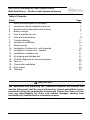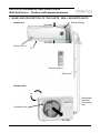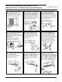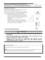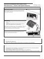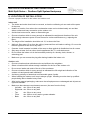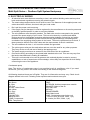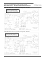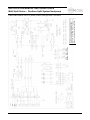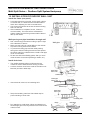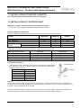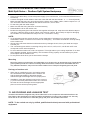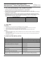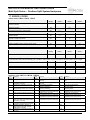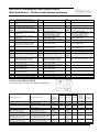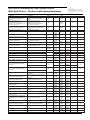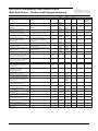
1
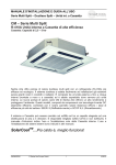
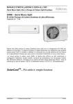
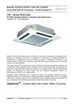
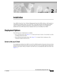
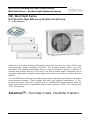
INSTALLATION MANUAL AND USERS GUIDE Multi Split Series – Ductless Split System Heatpump CM - Multi Split Series R-410A Ultra High Efficiency Ductless Heat Pump 5 – 12 kw Capacity Sedna Aire now offers ductless Multi split heat pumps that use the more efficient and environmentally friendly refrigerant (R-410A). The ductless system allows very easy integration into existing surroundings without major investment in ducts or radiators. It contains one outdoor and up to five indoor unit Wall mounted and/or Cassettes) and is especially dedicated to straight forward applications where more than one indoor unit are needed. The new CM Series of Sedna Aire heat pumps offers outstanding performance as well as environmental protection. These models with their high efficient compressors in DCInverter technology offer when matched with our SolarcoolTM panel efficiency rates 2-3 times better than current comparables best-in class systems: EER: 8 for Cooling and COP: 8 for Heating. SolarCoolTM…The Hotter it Gets, The Better It Works! 04006020101 © Sedna Aire Europe 1 12/2012 INSTALLATION MANUAL AND USERS GUIDE Multi Split Series – Ductless Split System Heatpump Table of Contents Topic 1. Name and descriptions of the parts 2. Instructions before installation and use 3. Remote control description and manual 4. Battery change 5. How to operate the unit 6. Care and maintenance 7. Trouble shooting 8. Location of installation 9. Electric wiring 10. Installation of indoor unit - wall mounted 11. Installation of indoor unit - cassette 12. Installation of outdoor unit 13. Air purging and leakage test 14. Fill with refrigerant for connection pipes 15. Test run 16. Check after installation 17. Error codes 18. Warranty Page 3 4 6 7 7 9 11 13 14 19 21 21 23 25 25 25 26 30 IMPORTANT The installation and especially the connection between the outdoor unit and the Solarpanel shall be only performed by trained and skilled service personnel having the appropriate instruments. Sedna Aire does not take over any responsibility for direct and indirect damages causing from installation by unskilled and/or untrained persons. 04006020101 © Sedna Aire Europe 2 12/2012 INSTALLATION MANUAL AND USERS GUIDE Multi Split Series – Ductless Split System Heatpump 1. NAME AND DESCRIPTION OF THE PARTS - WALL MOUNTED UNITS Indoor unit Setting Display Air intake Air outlet Surface panel Louver Remote Control Drain hose Outdoor unit Air intake Refrigerant pipe and connecting wire Condenser fan Air outlet 04006020101 © Sedna Aire Europe 3 12/2012 INSTALLATION MANUAL AND USERS GUIDE Multi Split Series – Ductless Split System Heatpump 2. INSTRUCTIONS BEFORE INSTALLATION AND USE Earth: The Ground wire of your outdoor and indoor units must be wired to the earth of your electricity supply acc. To local electrical building codes. If this lacks, please ask your service personnel to install it. Don’t connect the earth wire to gas pipes, water pipes, drainage pipes or any other improper conductors. ★ Air conditioners are ★ Don’t attempt to to operate at 200-230V / 1 phase. All other voltages are not permitted. They may destroy the unit. Be sure to have switched off the power supply when you are not using the unit for a longer time repair the air conditioner by yourself Wrong repair may cause an electric shock and may kill you ★ Don’t apply cold ★ If your detect unusual wind over longer time on you It may cause a cold and harm your health, especially over night when you sleep. phenomenons like smell or burning smoke, turn off immediately the unit. It may cause damage, electrical shocks and impact your health. ★ Don’t place a heater near the indoor unit of the air conditioner. Air flow from the combustion can cause insufficient heating up by the indoor unit. ★ Don’t block the inlet ★ Don’t step on the top ★ Keep flammable and outlet openings of indoor and outdoor unit. It can decrease the air conditioning capacity or a malfunction of the outdoor unit and place something heavy on it. Falling off the outdoor unit may cause damage to you and somebody else sprays and liquids at least 1 m away from the units. It may cause fire or explosion 04006020101 © Sedna Aire Europe 4 12/2012 INSTALLATION MANUAL AND USERS GUIDE Multi Split Series – Ductless Split System Heatpump ★ Please check, if the ★ Select an appropriate ★ Adjust direction of planned stand is firm If it is not, the unit may fall down and cause injury temperature depending on outside temperature Setting very low temperatures consumes very much electricity and money airflow appropriately Direct air flow by adjusting the louvers for vertical and horizontal direction by use of remote control Max 5 °C difference between in and out Louver left/ right adjustment Louver Top/ down adjustment ★ Don’t leave windows ★ Don’t blow the air ★ Don’t damage the and doors open for a longer time while running the unit. It can decrease the air conditioning capacity directly to and plants. It may impact their health, when not properly controlled power and signal cords. Don’t damage or cut the cords. If this has happened, contact service center or other trained and skilled electricians, since wrong repairs may kill you. ★ Don’t splash water on ★ Don’t insert your the indoor units. It can cause an electric shock and kill you hands or stick into the air intake or outlet vents It destroy the air guidance and unit. ★ Don’t use the air conditioner for any other as not designed purposes like, drying clothes, food, etc. It may overheat and the unit may be damaged. 04006020101 © Sedna Aire Europe 5 12/2012 INSTALLATION MANUAL AND USERS GUIDE Multi Split Series – Ductless Split System Heatpump 3. REMOTE CONTROL DESCRIPTION AND MANUAL Actual remote control may vary, but functionality remains 6 Swing Function: Press to set up&down swing angle of air guide louvers. Various static angles or a dynamic oscillating angle of the louver may be chosen: The first sign on the upper left row indicates the oscillating mode, while the others install a static angle. 7 1 2 3 4 5 Turns unit on and off Adjusts Temperature setting: (not in Auto mode) + to increase temperature, hold 2 sec. for fast change - to decrease temperature Change operation mode: press the mode button until you see the desired mode - Auto, sets automatically - Cool - Dry - Fan - Heat “I Feel” Enhanced Comfort: Press the button to switch this function on or off: Then the temperature sensor in the remote control and not in the wall unit will master the control. Air Function: Press to turn on or off 04006020101 © Sedna Aire Europe 24 Hour timer: Switch TIMER ON/TIMER OFF on or off. After pressing disappears and “ON” blinks. 00:00 is displayed. Press within 5 sec. “+” or “-“ to set time. Every press changes time by 1 min. Holding down the “+” “-“ buttons rapidly changes the time setting by 1 min. and then 10 min. After having set, press TIMERON/TIMER OFF within 5 sec. to confirm your input 8 Display light on/off: Switch display light on/off 9 Displays set temperature, room temperature or outdoor temperature. The temperature control range for the indoor unit is 16°C to 30°C. 10 “One Touch” sleep function: Press to set the unit to sleeping mode or wake it up again (in Cool, Dry, Heat mode) 11 Turbo Fan Press the button to cool or heat faster 12 Indoor fan delay: Press to set a fan delay ( ) of 10 min. after you have turned off unit in order to dry unit (only COOL& DRY mode) 13 Clock setting - to set current time When pressed once, the clock setting mode appears and blinks. Same logic as for the timer setting. After having set, confirm your choice by pressing “CLOCK” and then will be constantly displayed 14 Plasma Ion Generator (if available) Press the button to switch on or off 15 Adjustable 3-speed fan Press the button and “+” or “-“ to increase or decrease the desired fan speed Lock: Press “+” and “-“ simultaneously to lock or unlock. If locked, is displayed. When you press any button, blinks 3 times °F ↔ °C: Switch unit off and press simultaneously MODE and “-“ 6 12/2012 INSTALLATION MANUAL AND USERS GUIDE Multi Split Series – Ductless Split System Heatpump 4. BATTERY CHANGE 1 2 3 4 Press lid and remove it Take old batteries out (2 AAA dry cells) Insert new batteries (2 AAA dry cells) Insert lid again NOTE Don’t mix new and used batteries Remove batteries when unit is not be used for a longer time The batteries hold for appx. one year under usual conditions The remote control should be 1 m away from television or audio device, since it could interact under unfavorable conditions with them Displace batteries correctly. They are not standard household waste. USER NOTES The entire capacity of the indoor unit shall not exceed the capacity of the outdoor unit by 150% over a longer time. Otherwise it will reduce the overall capacity A breaker(Fuse) needs to be installed for each indoor unit and the capacity has to be according to the indoor unit’s electrical parameters. All indoor units are required to be centrally controlled by one switch, which enables to cut off electrical power in case of an emergency. The breakers act as short circuit prevention and to avoid abnormal overloads The main switch must be accessible easily and at all times Switch of power before cleaning and maintenance of the indoor units After having turned off the indoor units, they will continue to work for 20-70 sec. to deplete the residual cool/heat in the unit’s evaporator, while preparing for next operation. This is normal When the selected mode for the indoor unit does not correspond to the mode of the outdoor unit, the malfunction light will blink on the indoor unit or remote control. Change the operation mode or the indoor unit will stop after 5 sec without entry. The cooling mode is compatible with the Dry mode and the Fan mode is compatible with all modes. 5. HOW TO OPERATE THE UNIT 1 2 3 4 5 6 7 8 9 10 Connect the unit with power and set eventual breaker on. The unit starts. Note: When unit is powered off, the guide louver of the indoor unit will close When you press the ON/OFF button, the Power/Run indicator switches over to green and shows the running mode (Cool, Heat, Auto). The air conditioner starts now to run. Press the MODE button to switch between the various running modes. Press the SWING button to start or stop the automatic swing mode of the indoor units Press the FAN button to set the desired fan speed. Press the + or - button to set the desired room temperature. Press the SLEEP button to set the unit to sleep Press the TIMER button to set a predefined start and Stop time, for example when you are not around and want to get it started half an hour before you return Press + and - simultaneously and you may lock or unlock the remote control. A lock sign appears in the display Switch unit off. Then press Mode and - simultaneously and you may switch between °F or °C 04006020101 © Sedna Aire Europe 7 12/2012 INSTALLATION MANUAL AND USERS GUIDE Multi Split Series – Ductless Split System Heatpump Note: In the AUTO mode the unit will automatically adjust its running mode according to the room temperature. SPECIAL FUNCTIONS Dehumidifying (only in cooling mode) Moisture in the indoor unit will be removed after the unit has stopped. This is intended to avoid mildew in the indoor unit. When having set X-FAN on: After turning off the unit (On/Off button), the fan in the indoor unit will continue for further 10 min. If you want to stop that too, press X-FAN again. When having set X-FAN off: After turning off the unit (On/Off button), the unit will stop at once. Auto Run In the AUTO mode the unit will automatically adjust its running mode according to the room temperature. The preset temperature will not be displayed. Defrost: When the outdoor temperature is low but the humidity is high, the heat exchanger of outdoor unit may be frosted after the air conditioner has run for a period of time. This will decrease the heating effect. To set this mode on, switch unit off. Press Mode and X-Fan buttons simultaneously for switching on or off and store it to the control. If the unit is under defrost mode, H1 will appear instead of a shown temperature. If you choose heating, the H1 will appear and flicker for 5s. Press + or - and H1 will disappear and the preset temperature show up. Both the indoor fan and outdoor fan will be stopped during auto defrost. During defrost, steam might flow from the indoor unit. The defrosting is carried out until it is completed. All other programs are stacked and will resume upon completion of the defrost process. Dew at the air outlet: lf the unit runs for a longer time in the cooling mode together with an ambient relative humidity higher than 80% (door and windows are open), dew might drop out near the air outlet. Refrigerant recovery (only CMO36/42) Power indoor and outdoor units on. Set COOL mode. Press within five minutes (after having turned on the unit) the “LIGHT” button 3 times in 3 seconds. The display will show “F0”. Quit the recovery by sending any other signal from the remote control to the indoor unit or when the recovery has elapsed 10 minutes. 04006020101 © Sedna Aire Europe 8 12/2012 INSTALLATION MANUAL AND USERS GUIDE Multi Split Series – Ductless Split System Heatpump Emergency operation: When the remote control was lost or is damaged, emergency operation can be carried out as following: Open the cover front surface lit and you will see two handling switches. The manual switch is labeled AUTO/STOP, the other code switch differentiates between four different modes Manual switch: Press to switch between Auto mode and Off. In the Auto mode the unit will run and set the appropriate heating or cooling mode depending on set temperatures and current measured room temperature. Code switch: Move the lever to Auto and the unit starts the Auto mode as described above. Move it to Stop and the units shuts off. TEST and RUN are only for service personnel during installation. Manual switch Code switch 6. CARE AND MAINTENANCE CAUTION Turn off power and pull out the power plug before cleaning the air conditioner. Never spray or sprinkle water on the indoor unit for cleaning. You may get an electrical shock which could kill you Volatile liquids /e.g. thinner or gasolines) will damage the air conditioner. So wipe the units with a dry soft cloth or slightly moistened with water or cleanser. Clean the front panel When the indoor unit front panel is dirty, please use a cloth which is slightly moistened with warm water/cleanser under 40 °C, then dry it and wipe off the dirty spots. NOTE: The indoor units contains microcomputer components and circuit board in the display which are very sensitive against water. So don’t put any water into the interior of the indoor unit. 04006020101 © Sedna Aire Europe 9 12/2012 INSTALLATION MANUAL AND USERS GUIDE Multi Split Series – Ductless Split System Heatpump Clean the air filters in the indoor unit (all 3 months recommended) Take out the air filters: Open the surface panel, hold the tab of the air filter and raise it slightly. Then tale it out along the direction of the arrows (see right figure) Clean the filter Use a vacuum cleaner for removing the dust from the filter or Wash them with water and a mild cleanser and dry them in the shade (no full sun exposure) NOTE: Never use water above 45°C to wash filter. This can cause deformation or discoloration. Never parch it by fire, since this could cause a fire or deformation. Reinsert the filter Reinsert the filter along the direction of the arrow, then cover the surface panel and clasp it Maintenance of outdoor unit Turn power off Clear dust from outdoor unit Repaint the rubiginous place on the outdoor unit to prevent it from spreading Check before you use the unit Be sure that nothing obstructs the air outlet and intake vents Check that the unit is „earthened“, i.e. that the earth wire from the unit is connected with the ground/earth of your power supply in the house. Check whether the batteries in your remote control or still operational Check if the outdoor unit is standing firm on its base or rack. If not, contact your service center. 04006020101 © Sedna Aire Europe 10 12/2012 INSTALLATION MANUAL AND USERS GUIDE Multi Split Series – Ductless Split System Heatpump 7. TROUBLE SHOOTING Don’t try to repair the air conditioner by yourself. It may cause an electric shock and kill you or damage the unit. Contact authorized service center. Following checks prior to contact may save you money Fault Cause analysis Air conditioner does not run upon To protect the air conditioner upon immediate restart immediate restart after a stop after a stop, the microcomputer controller will delay the unit for 3 minutes before the air conditioner will run. Air conditioner blows out bad smell when it is initially started. The air conditioner itself has no bad smell. lf any, is the bad smell accumulated from environment. Solution: Clean the air filter . lf still any problem, the air conditioner shall be cleaned (Please contact Authorized Service Center) You may hear "water flowing" noise when the air conditioner is running. When the air conditioner is started, or the compressor is started or stopped during running or the air conditioner is stopped, sometimes you may hear "hua-hua" or "di-dudi-du" noise. This is the flowing sound of refrigerant other than fault. Sometimes a thin fog will flow out of the outlet when air conditioner is running in cooling mode. This might occur when indoor temperature and humidity are high. This is because the indoor air is quickly cooled down. After a period of time, the fog will disappear with the decrease of indoor temperature and humidity. You may hear a slight crack when the air conditioner is started or stopped. Air conditioner does not run. This is the sound of friction caused by expansion of panel or other parts due to the change of temperature. Check if power failure? Has circuit protection device has tripped? ls the voltage too high or too low? (To be tested by professional technicians). ls timer function correctly used? Air inlet or outlet of outdoor unit blocked? Air filter clogged by dust? All doors and windows closed? Air flow set to "LOW FAN"? Any other heating source in the room? Proper temperature setting ? Remote controller sometimes cannot execute control if the air conditioner is subject to abnormal interference or frequent switch of functions. To resume normal operation, just pull out the power and reinsert it properly. Is the remote control too far away from indoor unit or blocked by any obstacles? Check the battery in remote controller for power. lf low power, replace the battery. Check, if remote controller is damaged. Air conditioner has poor cooling (or heating) effect. Remote controller cannot execute control. 04006020101 © Sedna Aire Europe 11 12/2012 INSTALLATION MANUAL AND USERS GUIDE Multi Split Series – Ductless Split System Heatpump Don’t try to repair the air conditioner by yourself. It may cause an electric shock and kill you or damage the unit. Contact authorized service center. Following checks prior to contact may save you money Fault Cause analysis Water leaks from indoor unit. Air humidity is too high. Condensing water overflows. Joint of indoor unit drain pipe is loose. Water leaks from outdoor unit. Under cooling mode, water might condense on pipe or pipe joint due to cooling. Defrosted water flows out under heating or defrost (auto defrost) mode. Under cooling mode, water attached on heat exchanger will drip. No air blows out from indoor unit. When the temperature of indoor heat exchanger is low during heating process, the indoor unit will stop air blowing to prevent blowing of cold air (within 3 minutes). In HEAT mode: when outdoor temperature is low or humidity is high and much frost on the heat exchanger has developed, unit switches into automatic defrost mode. Indoor unit stops blowing air for 3-12 min. During this water may flow out or steam will appear Under dehumidify mode, the fan of indoor unit might be stopped sometimes to prevent evaporation of condensing water and inhibit the rise of temperature Moisture exists on outlet grill. lf the air conditioning is long running under high humidity, moisture might condense on the grill and drop down. lndoor unit gives out noise. The sound that the fan or compressor relay is switching (close/open). Air conditioner may give out sounds under defrost or when it is stopped. This is caused due to inverse flow of refrigerant in the unit. H1: Defrosting Is normal In the case of following events, please contact authorized service center Air conditioner gives out shrill noise during running. Air conditioner gives out bad smell during running. Water leaks indoors. Air break switch or leakage protection switch trips STOP THE AIR CONDITIONER AND PULL OUT THE POWER PLUG frequently. Liquids or water are poured into the machine or remote controller. Abnormal overheating of power cord and plug. 04006020101 © Sedna Aire Europe 12 12/2012 INSTALLATION MANUAL AND USERS GUIDE Multi Split Series – Ductless Split System Heatpump 8. LOCATION OF INSTALLATION Choose a proper location for the indoor and outdoor unit Indoor unit The intake and outlet should not be covered, so that the outflowing air can reach all the parts of the room Install in a location, from where the condensation water can be drained easily out and that allows a short and easy connection to the outdoor unit Avoid close heat sources, steam or flammable gas Choose a location which is strong enough to withstand the weight and vibration of the unit Allow enough clearance space to have access for routine maintenance e.g. replacing the filters . The height of the installation should be min. 2,2 m above the floor. Wall unit: Stay away 15 cm from the ceiling (measured from air intake to ceiling), 15 cm on the left and right side of the unit to any walls. Cassette: Install cassette in middle of the room to allow optimal air distribution into all corners Stay away at least 1m from other electric appliances like TV, audio devices etc. Do not locate the indoor unit in the immediate proximity of a laundry, bath, shower, or swimming pool. Make sure you can access the plug after having installed the indoor unit. Outdoor unit Choose a locations that minimizes noise and airflow to the neighbors. Select a location which allows enough ventilation for the fan of the outdoor unit. Do not cover intake and outlet of the air of the condenser. Choose a location which is strong enough to withstand the full weight and vibration of the outdoor unit and permits safe installation. Avoid any proximity to hazardous and flammable gases, liquids. When handling the outdoor unit, keep it always upright. Handling must be done by qualified people being able to handle heavy loads. After having opened packaging, make sure that all equipment are undamaged and all parts at right and available. Make sure that clearance requirements are met. (As seen from the front): Left side: min. 30 cm to any wall Right side: min. 50 cm to any wall Top: min. 50 cm to any cover Front: min. 200 cm to any wall or greater obstacle Back: min. 30 cm to any wall 04006020101 © Sedna Aire Europe 13 12/2012 INSTALLATION MANUAL AND USERS GUIDE Multi Split Series – Ductless Split System Heatpump 9. ELECTRICAL WIRING All electrical work must be done according to local and national building codes and any other local rand national regulations covering any electrical work. The rated voltage and exclusive circuit must be used. The diameter of the supplied power cord cables should be sufficient, but check with your local codes. Don’t pull the power cord too strong. If the supply cord is damaged, it must be replaced by the manufacturer or its service personnel or similarily qualified person in order to avoid any hazards The air conditioner must be safely earthed. The earth wire must be connected to the special ground of the power supply of your house. This has to be done by a certified and skilled service personnel. Appropriate protection switches against leakage of electricity and safety breakers have to be installed to protect life and the unit against damage, shortenings and overloads of the supplying wiring system in the house. The service personnel has to check, if these protection devices fit to local codes and the requirements of the air conditioner. The air conditioner is class 1, so it must be earthed and grounded. The yellow green wires are the earth wires and are not to be used for any other purposes. They may not be cut off and are to fixed by the tapping screw. The power supply must have an access for the earth wire of the air conditioner. Connect the wiring according to the printed label attached at the unit. This one may vary from the herein described and is leading at installation. This unit is not intended to be used by persons with reduced physical, mental or sensory capabilities or a lack of experience and knowledge, unless they are supervised for their safety concerning the use of the appliance. Condensate pump Note: The device of condensate pump is not provided at all air conditioner units. If you need the device, you may order it and install it according to the electrical diagrams. All following electrical charts are in English. They are for information and may vary. Check circuit diagram sticked in the unit. Following index explains used word and acronyms: BL: Black BN: Brown BL: Blue RD: Red YE/GN: Yellow/Green WH: White GY: Gray POWER: FAN MOTOR: INDOOR UNIT: COMP: Compressor TEM: Temperature 04006020101 © Sedna Aire Europe SENSOR: TUBE: OUTROOM: Ambient temperature outside EXHAUST: Outlet of the air STEP MOTOR: DISPLAY: TRANSFORMER: MAIN: Main board PUMP: Condensate pump indoor unit L: Hot Live wire (for 230V, 50Hz, 1 ph) L2: N-wire (for 230V, 50Hz, 1 ph) 14 12/2012 INSTALLATION MANUAL AND USERS GUIDE Multi Split Series – Ductless Split System Heatpump CMO 018B Outdoor unit for 2 (two) indoor units type CMI - 200-230V When the unit runs or was stopped less than 2 min. ago or if the voltage is less than 30V between P and N of IPM, then don*t touch any terminal. You may get a shock and be killed. CMO 024B Outdoor unit for 2 (two) indoor units type CMI - 200-230V When the unit runs or was stopped less than 2 min. ago or if the voltage is less than 30V between P and N of IPM, then don*t touch any terminal. You may get a shock and be killed. 04006020101 © Sedna Aire Europe 15 12/2012 INSTALLATION MANUAL AND USERS GUIDE Multi Split Series – Ductless Split System Heatpump When the unit runs or was stopped less than 2 min. ago or if the voltage is less than 30V between P and N of IPM, then don*t touch any terminal. You may get a shock and be killed. CMO 024B Outdoor unit for 3 (three) indoor units type CMI - 200-230V 04006020101 © Sedna Aire Europe 16 12/2012 INSTALLATION MANUAL AND USERS GUIDE Multi Split Series – Ductless Split System Heatpump When the unit runs or was stopped less than 2 min. ago or if the voltage is less than 30V between P and N of IPM, then don*t touch any terminal. You may get a shock and be killed. CMO 024B Outdoor unit for 4 (four) indoor units type CMI - 200-230V 04006020101 © Sedna Aire Europe 17 12/2012 INSTALLATION MANUAL AND USERS GUIDE Multi Split Series – Ductless Split System Heatpump CMI 09 and CMI12 Indoor units CMI18 Indoor unit 04006020101 © Sedna Aire Europe 18 12/2012 INSTALLATION MANUAL AND USERS GUIDE Multi Split Series – Ductless Split System Heatpump 10. INSTALLATION OF INDOOR WALL UNIT Install the frame (rear panel) Level with plumb line or leveler. As the drain outlet is on the left side, it is better that the left side shall be lower when adjusting the wall- mounted board Use screws and dowels to secure the wall-mounting frame on the wall After installation is completed, check, if frame is mounted safely. The frame has to withstand the weight of 60kg and the fixing screws shall be able to take up this stress. Wall opening and pipe installation through wall Drill a hole through the wall according to picture right with a diameter of 65mm Make sure the hole has a slight falling to the outside to prevent coming water from outside To prevent the fitting pipe and the cable passing through the wall from being harmed and also protect the hollow wall from rodents/insects, install a wall pipe cover on both sides. Fill the hole with foam/Sealing paste, after you have made all other connections (Drainage, cables, etc.) Wall pipe Seal pad Install drain hose The flexible drainage pipe must descend to the outside in order to allow smooth running of water. Connect the drain hose to the outlet of the indoor unit. Bind the joint with rubber tape Outlet pipe indoor unit Outlet pipe Drain hose Rubber tape Outlet pipe indoor unit Drain hose Insert the drain hose into an insulating tube Insulating tube Rubber tape Outlet pipe indoor unit Wrap the insulating tube with wide rubber tape to prevent shifting of inner tube Connected Bulge Pay attention to avoid twists, ridges and distortion of the drainage pipe in the Iayout and not to immerse the outlet in water. 04006020101 © Sedna Aire Europe Insulating tube Distortion Flooded 19 12/2012 INSTALLATION MANUAL AND USERS GUIDE Multi Split Series – Ductless Split System Heatpump Electrical connection of indoor and outdoor units Pull open the front panel of the indoor Unscrew the screw fixing the covering plate of terminal board.(See figure on the right) Pass the power cable through a separate cable duct on the back of indoor unit and pull it out from the front. Connect the Neutral wire of the power connection cables to the "N (1) "terminal of the terminal board, connect the Signal wire to the "2" terminal, and connect the L- wire to the "3" terminal and connect the earthing wire to the (earth) terminal Place the section of power cable with protective pipe into pressing groove and close the cover plate. Tighten the fixing screws to clamp the connecting cable. Put the front panel back into position Wiring cover Terminal N(1) - 2 - 3 - Earth/Ground) Wire clamp Power cord NOTES: If the connecting cables are too short, replace the whole cable from outdoor to indoor unit by a longer cable. No joints within the cable is allowed. Make sure you have the proper diameter for the extended length. When the cable gets longer, you might need to choose a cable with thicker diameter for the copper conductor. Don’t choose Aluminum conductors. Be sure to connect the cable correctly. lncorrect connections will cause fault to some electrical parts. Tighten the terminal screw to avoid looseness. After tightening the screw, gently pull the cable for tightness. lncorrect connection of earthing cable might cause electric shock. Be sure to fix the junction cover plate securely and press it closely against connecting cable. lmproper fixing of junction cover plate might allow dust or water to enter or expose connecting terminal directly under the external force, whereas fire or electric shock might occur. Install the indoor unit The refrigerant pipe can come out from four directions, i.e. right, rear right, left and rear left. Gas side pipe Electrical wiring Liquid side pipe Gas side pipe insulation Left Right Left Rear Drain hose Right Rear Liquid side pipe insulation Adhesive tape When positioning the refrigerant pipings (line) at the left or right side, cut the tailings in the casing of the indoor unit in the appropriate size. Wrapping tape Wrap the piping (incl. cables) by using adhesive tape and pass them through the cut-off-tailing holes . Refrigerant pipes Hung the claws at the rear side of the indoor unit to the hook on the wallmounting frame. Move the unit left and right to see if it is steady. Power cord The installation height of the indoor unit must be at least 2,0 m. 04006020101 © Sedna Aire Europe 20 Drainage hose 12/2012 INSTALLATION MANUAL AND USERS GUIDE Multi Split Series – Ductless Split System Heatpump 11. INSTALLATION OF INDOOR CASSETTE See separate manual for installation and user manuals 12. INSTALLATION OF OUTDOOR UNIT Modify the outdoor unit and connect it to SolarCool panel: Do this first ! See separate installation manual for SolarCool panel Piping lengths and diameters The piping lengths and altitudes between the outdoor and the indoor units are defined as: Product Number of indoor units Total length (m) Max. length for single indoor unit (m) Max installation Outdoor ↔ indoor unit altitude Indoor ↔ indoor unit CMO18/24 CMO28/36 CMO42 1-2 25 15 10 5 2-4 70 15 15 7,5 2-5 80 15 15 7,5 Following min. inner pipe diameters according to indoor units have to be used Capacity of indoor unit < 3,5 kW 3,6 → 5,3 kW 5,4 → 7,5 kW Outdoor ↔ Solarpanel Gas pipe Ø 9,52 mm - 3/8” Ø 12,7 mm - 1/2” Ø 15,9 mm - 5/8” Min. Ø 12 mm - 1/2” Liquid pipe Ø 6,35 mm - 1/4” Ø 6,35 mm - 1/4” Ø 9,52 mm - 3/8” Min. Ø 12 mm - 1/2” Connecting the pipes The taper end of the connecting pipe must be in line with the corresponding taper face of the valve joint. Tighten the nut of the connecting pipe and then spanner to tighten the nut. Hexagon nut Torque (Nm) Ø 6,5 - (1/4”) 15 - 20 Ø 9,5 - (3/8”) 31 - 35 Ø 12,7 - (1/2”) 50 - 55 Ø 15,8 - (5/8”) 60 - 65 Ø 19,0 - (3/4”) 70 - 75 Torque wrench use Spanner Flare nut Joint NOTE: Connect the connecting pipe to the indoor unit first and then connect it to the outdoor unit. Pay attention to the bending and Iayout when preparing the connecting pipe in order not to harm it. Do not screw the joint nut too tightly, otherwise leakage will be caused. Each pipe shall be labeled indicting to which indoor system it belongs in order to allow easier maintenance Insulate all pipes and joints to avoid condensate and to improve cooling/heating efficiency 04006020101 © Sedna Aire Europe 21 12/2012 INSTALLATION MANUAL AND USERS GUIDE Multi Split Series – Ductless Split System Heatpump Connecting the cables and power supply at the outdoor unit Remove the lid at the outdoor unit (right side or front beside condenser fan varying per series). You see a power connection terminal with 3 lugs (L, L2 and ) and then 2 to 5 terminals (depending on your outdoor unit) connecting the indoor unit (N, 2, 3 and the beside the terminal. L2 is same as N. CMO18 for 2 indoor units CMO24 for 2 indoor units 3 indoor units 4 indoor units (5 analog) 04006020101 © Sedna Aire Europe 22 12/2012 INSTALLATION MANUAL AND USERS GUIDE Multi Split Series – Ductless Split System Heatpump Remove the cable clamp, connect the power supply (L for hot/Live wire, L2 for neutral and Earth/Ground to Ground) Connect the signal control cables to the indoor units CMI with the terminals N1 - 2 - 3 - Ground (beside). Make sure that the wiring is in accordance with the indoor units. CMI09, CMI12, CMC12 require min 1,5 mm2 wire while CMI18 and CMC18 and CMC24 need min 2,5 mm2 wires Fix the wiring with the cable clamps. Make sure that the wiring has been connected securely Reassemble the lid on the outdoor unit Bundle the refrigerant pipes and electrical wire together with tape and wrap them with adhesive tape to one string. Label this string to which indoor unit it belongs. Caution. Do not wrap too tight for damaging the insulation. Fix the bundle with clamps min all 1,5 m at wall or ceiling. NOTE: An all-pole disconnection switch having a contact separation of at least 3mm in all poles should be assembled to switch off outdoor unit in case of an emergency . This switch off shall be in close proximity to the outdoor unit Wrong wiring will cause electrical malfunction and may damage the unit, harm your health and might even kill you. The connection pipes and the connecting wirings of the unit A ,unit B, unit C, unit D and unit E must correspond to each other respective. Do not install the outdoor unit in full sun exposure. This might reduce your cooling capacities. If no other place appears possible, look for shading. This increases cooling capacity and decreases your power consumption and the related costs. Do not pull the wires when you fix them with the clamps Mounting Mount the outdoor unit with heavy and suited bolts on to the ground or an appropriate rack. Perpendicular ground plates provide four holes for mounting. Make sure that the outdoor unit is assembled safe and may withstand vibrations, major wind and other weather forces. Wrap all refrigerant pipes and joints. Drainage of outdoor unit When the air-conditioning runs in the heating mode, the condensate water generated at the outdoor unit and the water generated by defrosting shall be drained through the drainage hose to a proper place. Installation: Insert the drainage hose into the ø 25 mm (1”) hole in the base plate of the outdoor unit. Connect the other end of the drainage hose an appropriate place to remove all the upcoming water. Drainage hose 13. AIR PURGING AND LEAKAGE TEST Humid air left inside the refrigerant may cause malfunction of the compressor and needs therefore to be bled. Refer to the specification for seeing possible combinations of indoor units to outdoor unit. Use only R410 and do not use mineral oil to clean the pipings and joints. Use suitable instruments. NOTE: To be carried out only by skilled, qualified and trained personnel with professional equipment. 04006020101 © Sedna Aire Europe 23 12/2012 INSTALLATION MANUAL AND USERS GUIDE Multi Split Series – Ductless Split System Heatpump Unscrew and remove the caps from the 2-way and 3- way valves. Unscrew and remove the cap from the service valve. Connect the vacuum pump hose to the service valve. Operate the vacuum pump for 10 - 15 minutes until an absolute vacuum of 0,01 bar (10 mm Hg) has been reached. With the vacuum pump still in operation, close the low-pressure knob on the vacuum pump coupling. Stop the vacuum pump. Vacuum pump Open the 2-way valve by 1/4 turn and then close it after 10 seconds. Check all the joints for leaks using liquid water/soap mixture or an electronic leak device. Vacuum pump Vacuum pump Refrigerant fluid direction flow 2 way valve 3 way valve Turn the body of the 2-way and 3-way valves. Disconnect the vacuum pump hose. Open by 1/4 turn Service inlet Turn Secure CMO28-3 and CMO28-4: For installing the CMI12 and CMI18 you need to use the conversion joint kit to enable thicker pipings. This increases the piping from 3/8“ to 1/2“. CMI09 may use further 3/8“ piping. Replace and tighten all the caps on the valves. 04006020101 © Sedna Aire Europe Turn to open fully Valve cap Turn to open fully Turn Secure Turn Valve cap Secure Hexagon nut Ø 6 - (1/4”) Ø 9,5 - (3/8”) Ø 12 - (1/2”) Ø 16 - (5/8”) Ø 19 - (3/4”) 24 Connect to the indoor unit Torque (Nm) 15 - 20 31 - 35 50 - 55 60 - 65 70 - 75 12/2012 INSTALLATION MANUAL AND USERS GUIDE Multi Split Series – Ductless Split System Heatpump 14. FILL WITH REFRIGERANT FOR CONNECTION PIPES Pressure: The suction line pressure: 900 Pa (CMO18/24);1 000 Pa(CMO28) (with indoor temperature 24°C/outdoor temperature 35°C in cooling mode) Standard length of connecting pipes (between indoor and outdoor unit): 5m – 7,5m – 8m CMO18/24: Add additional refrigerant only for the pipes between outdoor unit and solarpanel according to piping diameter and table below. CMO28/36/42: Additional refrigerant is ONLY required, when the total length of all pipings (indoor and solarpanel) exceeds 50 m. In that case add refrigerant charge for the pipe according to its inner diameter and the table below. Example: Total length is 65m and pipe diamter is 9,5 mm. Then additional refrigerant charge is (65 – 50) x 22 g/m = 330g Pipe inner diameter Ø 6,3 - 1/4” or Ø 9,5 - 3/8” or Ø 12 - 1/2” Ø 15,8 - 5/8” or Ø 19,0- 3/4” Ø 19,0 - 3/4” or Ø 22- 7/8” Ø 25,4- 1” or Ø 31,8- 1 1/4” Additional refrigerant ( g/m) 22 50 110 140 15. TEST RUN Preparation Do not switch on the power before all installation work is completed. Confirm that the control line is correctly installed and all electrical lines are firmly connected. Open the shutoff valves of the big and small connecting pipes. Remove all foreign articles, especially metal scraps, line ends and forceps, from the unit. Test run Connect to the power supply, press the "ON/OFF" key on the remote controller, and the air-conditioning unit starts to operate. Press the Mode key, select the operating modes such as Cool, Heat, Fan, Swing mode and observe if the operation is normal. 16. CHECK AFTER INSTALLATION Check ltems Problems Owing to Improper Installation ls the installation reliable? The unit may drop, vibrate or make noises Has the gas leakage been checked? ls the thermal insulation of the unit sufficient? ls the drainage smooth? May cause unsatisfactory cooling (heating) effect May cause condensation and water dropping May cause condensation and water dropping Does the power supply voltage accord with the rated voltage specified on the nameplate? The unit may bread down or the components may be burned out Are the lines and pipelines correctly installed? The unit may bread down or the components may be burned out Has the unit been safely grounded? Are the models of lines in conformity with requirements? Risk of electrical leakage The unit may bread down or the components may be burned out Are there any obstacles near the air inlet and outlet of the indoor and outdoor units? The unit may break down or the components may be burned out Have the length of refrigerating pipe and refrigerant charge amount been recorded? The wrong amount of refrigerant has be installed and causes insufficient cooling and heating 04006020101 © Sedna Aire Europe 25 12/2012 INSTALLATION MANUAL AND USERS GUIDE Multi Split Series – Ductless Split System Heatpump 17. ERROR CODES Indoor units CMI09, CMI12, CMI18 Temp. display Malfunction System abnormal (Very high temperature) Unit will stop, cooling overload Compressor overload protection Modes protection High pressure protection Anti-freeze protection. Unit will stop Air exhaust temperature protection Low voltage Modes conflict Communication malfunction Defrost or heating oil return lndoor ambient temp sensor opened, short circuit Any of indoor evaporator sensor opened, short circuit Outdoor ambient sensor opened, short circuit Outdoor condenser sensor opened, short circuit Outdoor air exhaust sensor opened, short circuit Running Light Blinks Heating Light Blinks H4 4x H3 H5 E1 E2 E4 E5 E7 E6 H1 F1 F2 F3 F4 F5 3x 5x Cooling Light Blinks 1x 2x 4x 5x 7x 6x 1x 1x 2x 3x 4x 5x Temp. Running Light Heating Light Cooling Light display Blinks Blinks Blinks Start up failure H7 7x PFC malfunction HC 6x Compressor demagnetization protection HE 14 x The following malfunction needs to use remote control, press within 3s press SLEEP button 6 times. Display shows up. After 5 min detention status will automatically quit . (invalid in Auto mode) or you press within 3s SLEEP button 6 times will quit. Over current frequency decline F6 6x Whole unit over current frequency decline F8 8x Compressor air exhaust frequency decline F9 9x Whole unit AC current voltage decline frequency decline EO 10 x Heating anti-high temperature frequency decline HO 10 x Anti-cool wind protection E9 9x Cooling oil return F7 7x Malfunction Outdoor units CMO18, CMO24, CMO28 D101 Meaning Blinks 1x Compressor operates 2x 3x 4x Compressor high pressure protection unit stop Air exhaust protection unit stop D102 Meaning Blinks 1x Air exhaust protection frequency reducing 2x Cooling overload frequency reducing 3x Over current protection frequency reducing 4x Phase current protection frequency reducing 5x Heating A unit anti-high temperature frequency reducing 6x Heating B unit anti-high temperature frequency reducing 7x Heating C unit anti-high temperature frequency reducing 8x Heating D unit anti-high temperature frequency reducing 5x Communication malfunction unit stop (Include indoor unit + driver IPM modular protection unit stop 6x Over current protection unit stop 7x Cooling overload unit stop 8x Each indoor unit starts heating at same time anti-high temperature protection unit stop Each indoor unit anti-freezing 9x protection at same time unit stop Outdoor unit temp. sensor or 10 x each indoor unit temp. sensor malfunction unit stop Compressor overload protection 11 x unit stop 9x 10 x 11 x 04006020101 © Sedna Aire Europe Defrosting D103 Meaning Blinks 1x Air exhaust protection frequency limit 2x Cooling overload frequency limit 3x 4x 5x 6x 7x 8x 9x Over current protection frequency limit Phase current protection frequency limit Heating A unit anti-high temperature frequency limit Heating B unit anti-high temperature frequency limit Heating C unit anti-high temperature frequency limit Heating D unit anti-high temperature frequency limit Defrosting 10 x 11 x 26 12/2012 INSTALLATION MANUAL AND USERS GUIDE Multi Split Series – Ductless Split System Heatpump 12 x 13 x Compressor low-pressure protection unit stop (preserved) Phase current protection unit stop E2 PROM Error unit stop DC power supply short circuit Meaning 12 x 12 x 13 x 13 x 14 x 15 x D104 Blinks 1x Outdoor ambient temp. sensor malfunction 14 x 15 x D105 Meaning Blinks 1x A unit communication malfunction (cannot receive correct data within 3 mins.) 2x Outdoor tube temp. sensor 2x A unit indoor middle temp. malfunction sensor malfunction 3x Outdoor air exhaust temp. 3x A unit indoor outlet pipe temp. sensor malfunction sensor malfunction 4x Communication malfunction with 4 x A unit indoor inlet pipe temp. driver (cannot receive correct sensor malfunction data from driver within 10s) 5x 5x A unit indoor ambient temp. sensor malfunction 6x 6x A unit modes conflict 7x 7x A unit anti-freezing protection 8x 8x A unit anti-high temp. protection D107 Meaning D108 Meaning Blinks Blinks 1x C unit communication 1x D unit communication malfunction (cannot receive malfunction (cannot receive correct data within 3 mins. ) correct data within 3 mins. ) 2x C unit indoor middle temp. 2x D unit indoor middle temp. sensor malfunction sensor malfunction 3x C unit indoor outlet pipe temp. 3x D unit indoor outlet pipe temp. sensor malfunction sensor malfunction 4x C unit indoor inlet pipe temp. 4x D unit indoor inlet pipe temp. sensor malfunction sensor malfunction 5x C unit indoor ambient temp. 5x D unit indoor ambient temp. sensor malfunction sensor malfunction 6x C unit modes conflict 6x D unit modes conflict 7x C unit anti-freezing protection 7x D unit anti-freezing protection 8x C unit anti-high temp. protection 8 x D unit anti-high temp. protection 14 x 15 x D106 Meaning Blinks 1x B unit communication malfunction (cannot receive correct data within 3 mins.) 2x B unit indoor middle temp. sensor malfunction 3x 4x B unit indoor inlet pipe temp. sensor malfunction 5x B unit indoor ambient temp. sensor malfunction B unit modes conflict B unit anti-freezing protection B unit anti-high temp. protection Meaning 6x 7x 8x D109 Blinks 1x Received communication data proof test correct will flash once 2x 3x 4x 5x 6x 7x 8x Outdoor units CMO36, CMO42 Errors to be seen on outdoor unit display (PCB Board) Outdoor Unit Display LED88 PCB boardy Residential AC Errors Commerical AC Errors / / Defrosting mode 1 Defrosting mode 2 08 0A / heating overload protection 0C / Short/open circuit of the liquid valve temperature sensor Short/open circuit of the gas valve temperature sensor Refrigerant insufficiency or blockage protection (available for the residential outdoor unit) Short/open circuit of the indoor ambient temperature sensor Short/open circuit of the indoor Normal running Short/open circuit of the liquid valve temperature sensor Short/open circuit of the gas valve temperature sensor Refrigerant insufficiency or blockage protection (available for the residential outdoor unit) Short/open circuit of the indoor ambient temperature sensor Short/open circuit of the indoor 04006020101 © Sedna Aire Europe ON Shown as Table 16 Shown as Table 16 F0 Indicating Lamp Running / / Flash 3 times / / / / Shown as Table 16 Shown as 27 / / Cooling / / Flash 3 times / Flash 19 times Flash 22 times Flash 10 times Flash once Flash Heating / / Flash 3 times / Lamp Panel Display (Floor Ceiling Type) / / / Wired Controller Display / / oE / / / b5 b5 / b7 b7 / oE oE / F1 F1 / F2 F2 12/2012 INSTALLATION MANUAL AND USERS GUIDE Multi Split Series – Ductless Split System Heatpump evaporator Short/open circuit of the of the outdoor ambient temperature sensor Short/open circuit of the temperature sensor at the midway of the condenser coil ( for the commercial unit) Oil returning in cooling evaporator Short/open circuit of the of the outdoor ambient temperature sensor Short/open circuit of the temperature sensor at the midway of the condenser coil ( for the commercial unit) Short/open circuit of the outdoor discharge temperature sensor Oil returning in cooling System high pressure protection System high pressure protection E1 Anti-freezing protection Anti-freezing protection E2 System low pressure protection E3 Compressor discharge high temperature protection E4 Whole unit over-current protection Whole unit over-current protection E5 Communication error between the indoor and outdoor units Communication error between the indoor and outdoor units Mode conflict Mode conflict Short/open circuit of the outdoor discharge temperature sensor System low pressure protection (reserved) Compressor discharge high temperature protection Table 16 F3 / F4 / Flash 4 times / F4 F4 F5 / Flash 5 times / F5 F5 F7 / Flash once Flash twice Flash 3 times Flash 4 times Flash 3 times Flash 6 times Flash 7 times Flash 3 times / / Quick flash Quick flash Flash 3 times / / / / / / E1 E1 / / E2 E2 / / E3 E3 / / E4 E4 oE oE / E6 E6 / E7 E7 oE oE / E9 / E9 dd dd Fo Fo oE oE Shown as Table 16 Shown as Table 16 Overload protection Overload protection E8 Anti cold blow protection / / Indoor unit water overflow error E9 Trial run/trial operation Trial run/trial operation dd Refrigerant recovery mode Refrigerant recovery mode Fo Drive module resetting(for the commercial unit) IPM Drive module resetting Min. cooling/ heating (capability test code) Cooling IPLV test Mid. Cooling/ heating (capability test code) P0 Cooling IPLV test Cooling level AA performance test / / Quick flash F3 Flash 3 times Flash 3 times / Flash Quick flash / Flash 3 times / P0 Quick flash P0 / P3 / P5 Flash 3 times Flash 3 times P6 Flash 3 times Flash 3 times Flash 3 times Flash 3 times Flash 3 times Flash 3 times Flash 3 times Flash 3 times Flash 3 times Flash 3 times Flash 3 times Flash 3 times Flash 3 times Flash 3 times Flash 3 times Flash 3 times Flash 3 times Flash 3 times Flash 3 times Flash 3 times Flash 3 times Flash 3 times Flash 3 times Flash 3 times Flash 3 times Flash 3 times Flash 3 times Flash 3 times Flash 3 times Flash 3 times Flash 3 times Flash 3 Flash 3 times Flash 3 times Flash 3 times Flash 3 times Flash 3 Flash 3 times Flash 3 times Flash 3 times Flash 3 times Flash 3 Module temperature protection P8 AC contact protection P9 Circuit sensor error Circuit sensor error Pc Transducer connection protection (for the commercial unit) Transducer connection protection Pd AC current protection(input side) AC current protection(input side) PA Temperature drift protection PE Drive board ambient temperature sensor error PF DC link high voltage protection DC link low voltage protection PL DC link low voltage protection DC link high voltage protection PH / Abnormal AC input voltage PP Capacitor charging error Capacitor charging error PU Jumper terminal error protection Jumper terminal error protection C5 © Sedna Aire Europe / Flash 3 times / Flash Quick flash Quick flash Flash 3 times Quick flash F3 / Level AA cooling performance test AC contact protection (for the commercial unit) 04006020101 / / Quick flash Flash 3 times Module temperature protection Temperature drift protection (for the commercial unit) Drive board ambient temperature sensor error (for the commercial unit) Flash 3 times / P3 Short/open circuit of the of the module temperature sensor Drive board communication error(for the commercial unit) / P0 Compressor over-current protection Communication error between the inverter driver to the main controller Short/open circuit of the of the module temperature sensor Phase over- current protection twice Flash 3 times P7 28 P0 P3 P3 oE oE oE oE oE oE oE oE oE oE oE oE oE oE oE oE oE oE oE oE oE oE oE oE oE oE oE oE oE oE 12/2012 INSTALLATION MANUAL AND USERS GUIDE Multi Split Series – Ductless Split System Heatpump times times times / / Flash once H1 Quick flash / Compressor overload protection. H3 Flash 3 times Flash 3 times M o d u l e c u r r e n t protection (namely IPM protection) IPM Module current protection H5 Compressor desynchronizing Compressor desynchronizing H7 PFC Protection PFC Protection HC Flash 3 times Flash 3 times Flash 3 times Flash 3 times Flash 3 times Flash 3 times Too high power protection (available for the residential outdoor unit) Too high power protection (available for the residential outdoor unit) L9 Flash 20 times / Compressor startup failure Compressor startup failure Lc Compressor phase failure/ reverse protection Compressor rotation failure(for the commercial unit) Compressor phase failure/ reverse protection Compressor rotation failure(for the commercial unit) Over speed (for commercial unit) Over speed LF Flash 3 times Flash 3 times Flash 3 times Flash 3 times Flash 3 times Flash 3 times Flash 3 times Flash 3 times / A5 / / / A7 / / EE / H1 Defrosting symbol displayed H1 H1 oE oE oE oE oE oE oE oE oE oE oE oE oE oE oE oE oE oE / / / / / / / / / / / / En / / / / / / EU / / / / / / F6 / / / / / F8 / / / / / F9 / Flash 9 times / / / / FH / Flash 2 times / / / H6 Flash 11 times / / / / HE / / / / / / / / / / Defrosting or oil returning in heating Defrosting or oil returning in heating H1 / Forcible defrosting Compressor thermal overload protection. Short/open circuit of temperature sensor at the inlet of the condenser coil ( for the commercial unit) Short/open circuit of temperature sensor at the outlet of condenser coil ( for the commercial unit) Memory card error Frequency limitation/ degradation for module circuit protection (for phase circuit) Frequency limitation/ degradation for module temperature protection Frequency limitation/ degradation for overload Frequency limitation / degradation for circuit protection of whole unit Frequency limitation/ degradation for module circuit protection (for phase circuit) Frequency limitation/ degradation for anti-freezing protection No indoor fan motor Compressor demagnetizing protection Indoor and outdoor units unmatched Compressor phase circuit detection error DC link voltage drop error Zero detection circuit error Nominal cooling/heating (capability test code) Max. cooling/heating (capability test code) 04006020101 Ld LE / LP / U1 / U3 / U8 / P1 / P2 © Sedna Aire Europe Flash 19 times / / / / / Flash 17 times 29 Flash 6 times Flash 8 times / Flash 3 times Flash 3 times Flash 3 times Flash 3 times / Flash 3 times Flash 3 times Flash 3 times Flash 3 times Flash 2 times / Flash 14 times / Flash 12 times Flash 20 times / / / / / / / / / / / / / / 12/2012 INSTALLATION MANUAL AND USERS GUIDE Multi Split Series – Ductless Split System Heatpump Error Code Error Description Error Code Error Code Error Description 26 Unit B mode conflict 36 Unit C mode conflict 17 27 Unit B anti- freezing protection 37 41 Unit D communication error 46 Unit D mode conflict 54 47 Unit D anti- freezing protection 55 Unit C anti- freezing protection Unit E indoor pipe inlet temperature sensor error Unit E indoor ambient temperature sensor error 51 Unit E communication error 56 Unit E mode conflict 57 Unit E anti- freezing protection C5 Jumper terminal error 13 14 15 16 42 43 44 45 Unit D indoor pipe midway temperature sensor error Unit D indoor unit pipe outlet temperature sensor error Unit D indoor pipe inlet temperature sensor error Unit D indoor ambient temperature sensor error 23 24 25 52 53 Unit B indoor unit pipe outlet temperature sensor error Unit B indoor pipe inlet temperature sensor error Unit B indoor ambient temperature sensor error Error Description Unit A indoor unit pipe outlet temperature sensor error Unit A indoor pipe inlet temperature sensor error Unit A indoor ambient temperature sensor error Unit A mode conflict Unit A anti- freezing protection Unit E indoor pipe midway temperature sensor error Unit E indoor unit pipe outlet temperature sensor error 33 34 35 Unit C indoor unit pipe outlet temperature sensor error Unit C indoor pipe inlet temperature sensor error Unit C indoor ambient temperature sensor error 18. WARRANTY Your HVAC comes with a warranty of 2 years for all parts. In order for your warranty to be effective, you must complete out this form and return it to Sedna Aire Europe. For full warranty coverage it needs an approval and signature from the certified and qualified service personnel. It is the responsibility of the owner to provide sufficient prove for its purchase and installation. We recommend to keep all documentations over the full warranty period. Location of installation Country Town Street Purchaser name Purchase Date Model Serial No Owner’s phone Owner’s email Owner’s signature Dealer’s name Installer’s name Installer’s address Installer’s signature/stamp Limited warranty by Sedna Aire Europe Valid is the warranty claim as published on the Homepage of Sedna Aire Europe at the time of purchase date. Sedna Aire hereby warrants to the consumer that all units are free from defects in materials and workmanship, and will replace or repair system components in accordance with the terms of this Limited Warranty. The terms of this warranty are effective from the date of installation, and apply only to products purchased and installed within Europe and Turkey. The installer shall be responsible for installation in accordance with the Sedna Aire Installation Manual and all building/electrical codes in effect at the time of installation. All transportation, service Iabor and diagnostic calls other than those specifically allowed by this Warranty are excluded. This Warranty shall not apply to damaged system components caused by transportation, improper installation, service or alteration, acts of God, improper electrical supply or refrigerant charge, corrosive atmosphere, m1suse or failure to properly maintain equipment. This Warranty does not apply to field-supplied and installed components for this system. If the warranty offered by Sedna Aire Europe on its Homepage differs from that written here, the always better for the customer applies. For details see www.sednaaireeurope.com All European certifications passed: CE CB EMC EMF GS LFGB RoHS Sedna Aire has a policy of continuous product and product data improvement and it reserves the right to change design and specifications without notice. SolarcoolTM is a trademark of Sedna Aire Europe 04006020101 © Sedna Aire Europe 30 12/2012