1
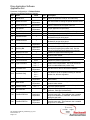
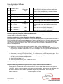
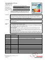
Drive Application Software
Application Set
Application Set Title
Virtual Encoder Position Follower with SL
Drive Product
PowerFlex 700S Phase II Drive
File Name for (AS)
AS_PF700SII_VirtEncdr_PositFollow_SL_A.dno
Date – Firmware Rev.
02/07/06
3.01
Attention:
This document and related file(s) are designed to
supplement configuration of the listed drive product. The
information provided does not replace the drive products
user manual and is intended for qualified personnel only.
Description:
The speed loop, position loop, and virtual encoder in the PowerFlex 700S Phase II drive will be
used to synchronize the speed and position of the master and followers. This document is for
setting up the followers. Electronic gearing can be used to match the speed of PowerFlex
700S Phase II drives with different mechanical gear ratios or electronic gearing can be used to
make the PowerFlex 700S Phase II drives run at different ratios.
Limitations:
Requires that the motors connected to each PowerFlex 700S Phase II drive have encoders.
Requires dynamic braking or other method of dissipating regenerative energy in order to follow
during deceleration.
Options &
Notes:
Default configuration for 3Wire Control through digital inputs may be changed to 2Wire Control
or for operation through 20-COMM-x module.
This configuration is set for external dynamic braking. The values for P416 [Brake PulseWatts]
and P417 [Brake Watts] must be loaded by the user.
After downloading the *.dno file, power must be cycled on the master and follower drives to
initialize SynchLink.
After downloading *.dno file, the Motor Data, Fdbk Config, Pwr Circuit Diag, Direction Test,
Motor Tests, and Inertia Measure parts of the Startup routine should be performed to auto-tune
the PF700S2 drive to the motor.
Please see the notes at the end of this document for information on independently jogging the
master and follower drives, using the position offset, and setting up the electronic gear ratios.
Drive Input & Output Connections:
Inputs
Function
DI 1
DI 2
DI 3
Jog 1
DI 4
DI 5
DI 6
AI 1
AI 2
AI 3
Encoder 0
Encoder 1
Outputs
DO 1
DO 2
DO 3
AO 1
AO 2
AO 3
Description
This Option is used to independently jog the PF700S2 follower drive
when the drive is not operating as a position follower.
Start
Stop
Motor Feedback
Encoder Input 0 is wired to the encoder on the Follower Motor.
Function
Description
AS_PF700SII_VirtEncdr_PositFollow_SL_A.doc
Form Revision – A
Page 1 of 5
Drive Application Software
Application Set
Parameter Configurations – Follower Drives
Changes from Default Parameter Settings
Par
Name
Value
12
Speed Ref 2
13
Speed Ref 2 Mul
Application
Dependent
27
Speed Ref A Sel
Speed Ref 2
29
Jog Speed 1
23
24
Speed Trim 3
SpdTrim 3 Scale
0.003
57
InertiaAccelGain
1
58
InertiaDecelGain
1
89
Spd Err Filt BW
Application
Dependent
90
Spd Reg BW
Application
Dependent
95
SRegOut Filt Gain
1
128
Regen Power Lim
-2
146
147
FW Task Time Sel
FW Functions En
151
Logic Command
232
Encoder0 PPR
414
Bus/Brake Cnfg
416
Brake PulseWatts
417
Brake Watts
2
b16=1
b0 = 1
b10 = 1
b13 = 1
Application
Dependent
b0 = 1
b1 = 1
b2 = 1
b3 = 1
Application
Dependent
Application
Dependent
740
Position Control
743
Aux Posit Ref
745
PositRef EGR Mul
Application
Dependent
746
PositRef EGR Div
Application
Dependent
Link
929
See notes below on setting the speed reference scale.
Speed Reference 2, which comes from the virtual
master is selected as the speed reference.
Application
Dependent
Set per application requirements.
55
Speed Trim 3 comes from P55 [Speed Comp].
The multiplier for speed compensation.
Inertia comp will add 100% of the required
acceleration torque during accel.
Inertia comp will subtract 100% of the required
deceleration torque during decel.
Set to > 5 * P90 [Spd Reg BW]
Gain of the speed loop. The speed loop should be
tuned before enabling the position loop. See the
PowerFlex700S Reference Manual for tuning tips.
Disables the feed forward lead lag filter.
Allows up to 200% regenerative power to flow to the
dynamic brake resistor.
Selects the regulators task time.
Enables the position regulator task.
Bit 0 is on to disable the speed ramp. Bit 10 is on to
enable inertia compensation. Bit 13 can be turned
on/off to enable/disable the position loop.
Sets the PPR for the PF700S motor feedback.
Sets the drive up to do dynamic braking w/ external
resistor first, then bus regulation.
b01 = 1
930
AS_PF700SII_VirtEncdr_PositFollow_SL_A.doc
Form Revision – A
Page 2 of 5
Description
The value for Speed Ref 2 comes from the virtual
master on Synchlink, P929 [SL Dir Data Rx00]
Sets the watt-second rating of the external dynamic
brake resistor.
Sets the continuous watt rating of the external
dynamic brake resistor.
Bit 1 is turned on to send the output of the position
loop to the speed regulator.
The position reference comes from the master over
Synchlink. P930 [SL Dir Data Rx01]
This sets the multiplier for the position reference
electronic gear ratio. This parameter has a settable
range from -2000000 to +2000000. See notes on
setting the gear ratio.
This sets the divider for the position reference
electronic gear ratio. This parameter has a settable
range from 1 to 2000000.
Drive Application Software
Application Set
Application
Dependent
768
PositRef P Gain
827
DigIn3 Sel
828
829
928
904
DigIn4 Sel
DigIn5 Sel
Rx Dir Data Type
SL Node Cnfg
Start
Normal Stop
b0 = 1
b2 = 1
905
SL Rx Format
9 – 0A, 4D,
8B
910
SL Tx Format
9 – 0A, 4D,
8B
911
SL Tx DirectSel 0
912
SL Tx DirectSel 1
Jog 1
22 – Dir Rx
Data
22 – Dir Rx
Data
Sets the proportional gain for the position loop. Set
this to 1/5th of P90 after done tuning the speed loop.
Used to independently jog the PF700S2 follower drive
when the drive is not operating as a position follower.
Start input for 3Wire Control.
Stop input for 3Wire Control.
Direct Data configured as Real.
Configures the follower drive to synch to the master.
Selects the format of the receive data to receive 4
direct words @ 50µsec and 8 buffered words @ 0.25
msec.
Selects the format of the transmit data to transmit 4
direct words @ 50µsec and 8 buffered words @ 0.25
msec.
Sends on the value of P43 [S Curve Spd Ref] from the
Master drive to the next drive on Synchlink.
Sends on the value of P62 [Virt Encdr Posit] from the
Master drive to the next drive on Synchlink.
Notes for jogging the PowerFlex 700S drives independently:
Command Jog 1 through a digital input or communication network. During a jog command, the position loop
output of the drive is automatically disabled.
Notes for controlling the position offset of the PowerFlex 700S drives:
Before advancing or retarding the PF700S drive, P755 [Posit Offset Spd] needs to be set to a value other than 0.
P755 [Posit Offset Spd] sets the speed change used to advance or retard the drive. During the advance or retard
operation it is added or subtracted from the speed the drive is already running at. P755 [Posit Offset Spd] is in
units of RPMs, and is set to a positive value. P755 [Posit Offset Spd] can remain set throughout the PF700S
follower’s normal operation.
Then to advance or retard the drive using a relative position offset, perform the following steps:
1. Add a value (in counts) in P753 [Posit Offset 1]. For a positive move, add a positive value to P753. For a
negative move, set add a negative value to P753. For example, with a 1024 ppr encoder, add a value of
4096 to P753 to advance the drive forward one motor revolution.
To advance or retard the drive using an absolute position offset, perform the following steps:
1. Set a value (in counts) in P753 [Posit Offset 1]. For a positive move, set P753 to a positive value. For a
negative move, set P753 to a negative value. For example, with a 1024 ppr encoder, set P753 to a value
of 4096 to move forward one motor revolution.
2. After the move is done, set P740 [Position Control], bit 5 “X Offset Ref” to a 1.
3. Set P753 [Posit Offset 1] = 0.
4. Set P740 [Position Control], bit 5 “X Offset Ref” to a 0.
P753 [Posit Offset 1] and P740 [Position Control] can be controlled over a communication network.
Notes for setting the gear ratio and speed reference scaling on the PowerFlex 700S drives:
Example 1: Matching speeds of (2) machines with different mechanical gear ratios
In this example, the each motor has a 1024 PPR encoder and the virtual master encoder is also setup for
1024 EPR. There is a gear box between each motor and each machine. Each gear box has a different ratio.
We want to match the speeds on the output side of the gear box (machine side). Here is the given
information:
PPRm =1024 PPR
Inputm:Outputm = 533:236
AS_PF700SII_VirtEncdr_PositFollow_SL_A.doc
Form Revision – A
Page 3 of 5
Drive Application Software
Application Set
PPRf = 1024 PPR
Inputm:Outputf = 533:163
where
PPRm = the PPR of the master encoder
PPRf = the PPR of the follower encoder
Inputm:Outputm = gear ratio of master gear box (number of input teeth:number of output teeth)
Inputf:Outputf = gear ratio for follower gear box (number of input teeth:number of output teeth)
PPRf • Inputf • Outputm
P745
1024 • 533 • 236
=
=
P746 PPRm • Inputm • Outputf 1024 • 533 • 163
Solving for the lowest common denominator, the 1024s on the top and bottom cancel out and the 533s on the
top and bottom cancel out so that:
P745 236
=
P746 163
Therefore, P745 [PositRef EGR Mul] = 236 and P745 [PositRef EGR Div] = 163. This will close the position
loop and the angular velocities of the master and follower will match exactly.
P13 [Speed Ref 2 Mult] is calculated:
P13 =
Inputf • Outputm 533 • 236
=
= 1.4479
Inputm • Outputf
533 • 163
Notice that the encoder PPRs should not be included in the calculation for P11.
This parameter is rounded to the 4th decimal place. The position loop gear ratios will be exact, so that the
master and follower track exactly.
Example 2: Using electronic gearing to make the (2) machines run at different ratios.
In this example, the each motor has a 1024 PPR encoder and the virtual master encoder is also setup for
1024 EPR. The motors are directly coupled to the load and we want the follower to run at 4 times the speed
of the master.
PPRm =1024 PPR
PPRf = 1024 PPR
Ratiof:Ratiom = 4:1
where
PPRm = the PPR of the master encoder
PPRf = the PPR of the follower encoder
Ratiof:Ratiom = the desired ratio between the follower speed and the master speed
P745
PPRf • Ratiof
1024 • 4
=
=
P746 PPRm • Ratiom 1024 • 1
Solving for the lowest common denominator, the 1024s on the top and bottom cancel out so that:
P745 4
=
P746 1
Therefore, P745 [PositRef EGR Mul] = 4 and P745 [PositRef EGR Div] = 1. This will set up the position loop
of the follower to move 4 counts for every 1 count of the master.
P13 [Speed Ref 2 Mult] is calculated:
P13 =
4
Ratiof
= = 4.0000
Ratiom 1
Notice that the encoder PPRs should not be included in the calculation for P11.
This parameter is rounded to the 4th decimal place. The position loop gear ratios will be exact, so that the
follower tracks at 4 times the master’s speed.
AS_PF700SII_VirtEncdr_PositFollow_SL_A.doc
Form Revision – A
Page 4 of 5
Drive Application Software
Application Set
AS_PF700SII_VirtEncdr_PositFollow_SL_A.doc
Form Revision – A
Page 5 of 5