1
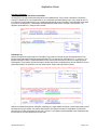
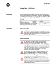
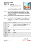
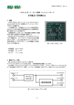
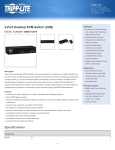
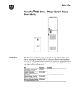
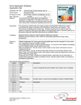
Application Guide
Topic:
Absolute Point to Point Positioning
Drive Product:
PowerFlex 700S – Phase I Control
Introduction
An Application Guide provides generic information on features and functions of drive products and their
implementation. Application Guides are not specific to any one application, but generically discuss
application techniques and/or functions as part of an application.
User Information
Solid state equipment has operational characteristics differing from those of electromechanical
equipment. Safety Guidelines for the Application, Installation and Maintenance of Solid State Controls
(Publication SGI-1.1 available from your local Rockwell Automation sales office or online at
http://www.ab.com/documents/gi) describes some important differences between solid state equipment
and hard-wired electromechanical devices. Because of this difference, and because of the wide variety
of uses for solid state equipment, all persons responsible for applying this equipment must satisfy
themselves that each intended application of this equipment is acceptable.
In no event will Rockwell Automation, Inc. be responsible or liable for indirect or consequential damages
resulting from the use or application of this equipment.
The examples and diagrams in this document are included solely for illustrative purposes. Because of
the many variables and requirements associated with any particular installation, Rockwell Automation,
Inc. cannot assume responsibility or liability for actual use based on the examples and diagrams.
No patent liability is assumed by Rockwell Automation, Inc. with respect to use of information, circuits,
equipment, or software described in this document.
Reproduction of the contents of this document, in whole or in part, without written permission of Rockwell
Automation, Inc. is prohibited.
Related Publications The following publications should be referenced and followed when operating, configuring, or
commissioning this drive product. These publications may be found on the automation book store at
www.theautomationbookstore.com ;
Publication Title
Pub Number
PowerFlex 700S Phase I Control User Manual
PowerFlex 700S Phase I Control Reference Manual
PowerFlex 700S Phase I Control Firmware Release Notes
PowerFlex 700S Phase I Control Quick Start
20-COMM-x User Manuals
20D-UM001
PFLEX-RM002
20D-RN004
20D-QS001
20COMM-UM00x
Also, the Application Set, AS_PF700S_AbsPtPtPosition, is used in conjunction with this Application
Guide.
20D-AP004A-EN-E.doc - Sept 19, 2003
Application Guide
Precautions
Class 1 LED Product
ATTENTION: Hazard of permanent eye damage exists when using optical transmission equipment.
This product emits intense light and invisible radiation. Do not look into module ports or fiber optic cable
connectors.
General Precautions
ATTENTION: This drive contains ESD (Electrostatic Discharge) sensitive parts and assemblies. Static
control precautions are required when installing, testing, servicing or repairing this assembly.
Component damage may result if ESD control procedures are not followed. If you are not familiar with
static control procedures, reference Allen Bradley publication 8000-4.5.2, “Guarding Against Electrostatic
Damage” or any other applicable ESD protection handbook.
ATTENTION: An incorrectly applied or installed drive can result in component damage or a reduction in
product life. Wiring or application errors such as under sizing the motor, incorrect or inadequate AC
supply, or excessive surrounding air temperatures may result in malfunction of the system.
ATTENTION: Only qualified personnel familiar with the PowerFlex 700S AC Drive and associated
machinery should plan or implement the installation, start-up and subsequent maintenance of the system.
Failure to comply may result in personal injury and/or equipment damage.
ATTENTION: To avoid an electric shock hazard, verify that the voltage on the bus capacitors has
discharged before performing any work on the drive. Measure the DC bus voltage at the +DC & –DC
terminals of the Power Terminal Block (refer to Chapter 1 in the PowerFlex 700S User Manual for
location). The voltage must be zero.
ATTENTION: Risk of injury or equipment damage exists. DPI or SCANport host products must not be
directly connected together via 1202 cables. Unpredictable behavior can result if two or more devices
are connected in this manner.
ATTENTION: Risk of injury or equipment damage exists. Parameters 365 [Encdr0 Loss Cnfg] - 394
[VoltFdbkLossCnfg] let you determine the action of the drive in response to operating anomalies.
Precautions should be taken to ensure that the settings of these parameters do not create hazards of
injury or equipment damage.
ATTENTION: Risk of injury or equipment damage exists. Parameters 383 [SL CommLoss Data] - 392
[NetLoss DPI Cnfg] let you determine the action of the drive if communications are disrupted. You can
set these parameters so the drive continues to run. Precautions should be taken to ensure the settings
of these parameters do not create hazards of injury or equipment damage.
20D-AP004A-EN-E.doc
Page 2 of 10
Application Guide
Description
The absolute point to point positioning mode may be configured to operate in an absolute mode in firmware revision 1.14 or later. The
absolute mode allows the point to point position regulator to remain active at all times, even when the drive is stopped and restarted.
In this application guideline, a Stegmann Hi-Resolution multi-turn encoder is also used. Stegmann Hi-Resolution encoders provide
absolute position feedback for up to 4096 motor revolutions. These Stegmann encoders can be used to remember their position
during power loss (for up to 4096 motor revs). As presented in this application guideline, an external controller and a 20-COMM-x
module on the drive may be used when absolute positioning is required. Although not shown in this application guideline, DriveLogix
may also be used when absolute positioning is required.
Below is a block diagram of the Point to Point Position Regulator:
Posit Ref Sel
Σ
742
744
* PositRef EGR Out
Accum
See Interpolated/Direct
Position Control Diagram
Page 6
0
∆
[ N]
[D]
1
Deriv
Gear Rat
2
Pt-Pt Posit Ref
758
740
Reref
10
741
157
PositRef EGR Div
746
Position Cmmd
Σ
747
*
Accum
∆
Deriv
Posit Offset 1
753
Posit Offset 2
754
Posit Offset Spd
Logic Ctrl State
(Position En)
745
4
Position Status
(PtPtRRef Act)
Position Control
(Pt-Pt ReRef)
PositRef EGR Mul
+
+
X Offst SpdFilt
Rate Lim
755
Filter
756
LPass
Position Control
(X Offset Pol)
740
04
Position Control
(X Offset Ref)
740
05
03
Logic Cntrl State [8G5]
0
157
03
&
Output Enable
740
Mtr Posit Fdbk
from Speed/Posit
Fdbk [9H2]
762
Σ
+
∆
-
0
Position Error
Limit
Point to Point Position
Σ
Accum
763
*Act Motor Posit
0
Posit Spd Output
1
769
Accum
Deriv
01
PositReg P Gain
768
Pt-Pt Filt BW
761
Pt-Pt Accel Time
759
Pt-Pt Decel Time
760
XReg Spd LoLim
775
XReg Spd HiLim
776
318
to Speed Control
- Regulator [3A2]
Position Status
741
02
(X Spd LLim)
741
03
(X Spd HLim)
Overview
The example presented in this paper is a point to point application requiring absolute positioning. A Stegmann Hi-Resolution encoder
is used for absolute position feedback. An external controller is used to store and select the point to point positions, send the selected
point to point position reference to the drive, and trigger the power-up initialization of the drive’s position loop. Although the initial
commissioning configuration values are set at the drive parameter level in this example, they may also be set from the controller if
necessary. An optional manual jog function is also described in this example.
20D-AP004A-EN-E.doc
Page 3 of 10
Application Guide
Drive Configuration
Required Links
Destination
Name
Parameter #
22
[Speed Trim 2]
758
[Pt-Pt Posit Ref]
Å
Å
Source
Parameter #
318
707
Name
Purpose
[Posit Spd Output]
[Data In A1]
Default Link
Point to Point Position Reference
Name
Purpose
[Position Status]
[Position Cmd]
[Act Motor Posit]
[Data In A1]
Destination
Parameter #
724
726
728
730
Name
[Data Out A1 Int]
[Data Out A2 Int]
[Data Out B1 Int]
[Data Out B2 Int]
Å
Å
Å
Å
Source
Parameter #
741
747
763
707
732
[Data Out C1 Int]
Å
740
[Position Control]
Position Regulator Status Word
Accumulated Position Command
Accumulated Motor Position Feedback
Echo back of Pt-Pt Posit Ref for initialization
process
Echo back of Position Control
Name
Description
[Pt-Pt Accel Time]
[Pt-Pt Decel Time]
[XReg Spd LoLim]
Å
Å
Å
Source
Parameter #
710
712
714
[Data In A2 Real]
[Data In B1 Real]
[Data In B2 Real]
[XReg Spd HiLim]
Å
716
[Data In C1 Real]
Positioning Acceleration Time
Positioning Deceleration Time
Minimum Positioning Speed, scaled so 1
per unit = P4 [Motor NP RPM]
Maximum Positioning Speed, scaled so 1
per unit = P4 [Motor NP RPM]
Optional Links
Destination
Parameter #
759
760
775
776
Name
Note: P759, 760, 775, and 776 are all floating point. In the controller they can be floating point tags or addresses, but are sent out as
32 bit integers, or (2) 16 bit integers. Refer to the appropriate 20-COMM section of the PowerFlex 700S Reference Manual for details
on handling floating point data with various networks and controllers.
Parameter Settings
P16 [Speed Ref Sel] = 0 – Zero Speed. This ensures that the sole source for speed reference is the position regulator. There are
several ways to accomplish this, but by using this method, the jog speeds may still be used to manually move the load. When using
the jog function, the position regulator must be disabled to allow the jog reference to move the load.
A pplied Logic Cmd
16
Speed Ref Sel
10
Speed Ref 1
Spd Ref 1 Div ide
11
Speed Ref 2
12
Spd Ref 2 Multi
13
Speed Ref 4
14
Speed Ref 5
15
Speed Ref DPI
*
0
/
0
1
2
X
+
20
152
3
0
Jog Speed 1
17
18
18
152
23
0
1
1
Jog Speed 2
4
5
6
P17 [Jog Speed 1] = 100 RPM. Sets the speed for a jog forward.
P18 [Jog Speed 2] = -100 RPM. Sets the speed for a jog reverse.
20D-AP004A-EN-E.doc
Page 4 of 10
Application Guide
P151 [Logic Command] = Bit 13 (PositionEnbl) on. All other bits off. This parameter, although called logic command, does not come
from the controller. Setting bit 13 (PositionEnbl) enables the position regulator, to allow tracking position while stopped and while
parameter 740 [Position Control], bit 1 (Speed Out En) is turned off.
P153 [Control Options] = bit 0 (Bipolar Sref) on, all other bits off. Bit 0 enables a bipolar speed reference, so we can send a positive
and negative jog speed. All other bits off configures the drive for 2 wire control so that we only need to send one signal to start and
stop the drive from our controller.
P222 [Motor Fdbk Sel] = 5 – FB Opt Port0. This selects the Stegmann Hi-Resolution feedback option as the primary feedback source.
P365 [Encdr0 Loss Cnfg] = 0 – Ignore. Encoder 0 is not used in this application, so the drive is set to ignore it.
P367 [FB Opt0 Loss Cnfg] = 2 – FltCoastStop. Configures the drive to fault and perform a coast stop when feedback loss from the
Stegmann is detected.
P740 [Position Control] = 656770 (bits 1, 7, 8, 10, 17 and 19 on. All other bits are off.) This is the setting for P740 immediately after a
power loss. Setting bit 1 (Speed Out En) allows the output of the position loop to enter the speed regulator. Setting bit 7 (Absolute
Mode) allows the drive to track position while stopped and while bit 1 (Speed Out En] is off. Setting bit 8 (Xzero Preset) causes all of
the accumulated registers of the position regulator to be loaded with the following after a power loss: P762 [Mtr Posit Fdbk] – P757
[Abs Posit Offset].
The accumulated registers include parameter 744 [PositRef EGR Out], parameter 747 [Position Cmd], and parameter 763 [Act Motor
Posit]. Bits 17 and 19 are on because they are factory default settings, but are not significant for this application guideline.
Note that the value of P740 will be changed by a message instruction from the controller after power loss and for doing jogs. P740 is
not set by a datalink from the controller because datalinks write to volatile memory (not written to EEPROM), so during power up any
parameters written to by a datalink are temporarily set to zero. P740 cannot be set to zero because bit 8 needs to be permanently set,
even on power up, or the accumulated registers will be reset to zero. Instead of a datalink, we set P740 directly in the drive so that bits
1, 7, 8, and 10, 17, and 19 are set in non-volatile memory and will always be on during power up. Then when we need to change P740
a message instruction is used to write to volatile memory.
P742 [Posit Ref Sel] = 2 – Pt to Pt. This selects point to point mode and selects parameter 758 [Pt-Pt Posit Ref] as the reference
source for the position regulator.
Posit Ref Sel
742
0
1
2
758
740
Position Control
(Pt-Pt ReRef)
10
Reref
741
4
Position Status
(PtPtRRef Act)
P757 [Abs Posit Offset] = 0. When P757 [Abs Posit Offset] = 0, the accumulated registers get loaded with the following value after a
power loss or toggling of P151, bit 13: P762 [Mtr Posit Fdbk] – P757 [Abs Posit Offset] = P762 [Mtr Posit Fdbk] – 0 = [Mtr Posit Fdbk]
P838 [DigIn1 Sel] = 0 – Not Used. Set to “Not Used” for AC input applications. DigIn1 is a default of 14-PreChrg/Disc, which is used
only for common dc bus applications.
P850 [ParamAccessLevel] = 1 – Advanced. Set to allow access to all parameters from the HIM.
20D-AP004A-EN-E.doc
Page 5 of 10
Application Guide
Controller Configuration
Controlling the PowerFlex 700S in Point to Point Mode
For starting in Pt to Pt mode, the drive was configured for 2 wire (maintained start). Rung 0 checks to see that the P740 [Position
Control], bit 1 (Speed Out En) is on and that the drive is not in re-reference mode before allowing a start. Rung 1 sends the user’s Pt
to Pt reference to the drive when the drive is not in re-reference mode and after the drive is enabled. PtPtRotationalRef can be scaled
by the user for any desired units. In this example, PtPtRotationalRef was scaled so that 1 unit equals 1 motor revolution. The
Stegmann counts 1048576 (220) counts per motor revolution.
Performing a Jog
After the user requests the jog (UserJogFwd or UserJogRev), Rung 2 performs a one-shot to move the appropriate value to P740
[Position Control] and request a enable the message to change P740. The value for P740 is 655744 (bits 7, 8, 17, and 19 on). The
significant setting here is that bit 1 (speed output enable) is off, so that the output of the point to point loop is no longer going to the
speed regulator. Rung 3 sends a jog forward command to the drive while the user is requesting the jog, and we verified that P740 bit 1
(speed output enable) is off and the drive is not in re-reference mode. Rung 4 sends a jog reverse command.
After the user releases UserJogFwd or UserJogRev, and the drive is no longer enabled, and P740 bit 1 (speed output enable) is still off,
we indicate that the jog is complete. We must also load P758 [Pt-Pt Posit Ref] with the value in P763 [Act Motor Posit] so that the
drive does not move when started in point to point mode. The user’s Pt to Pt reference (PtPtRotationalRef) is also recalculated so that
the drive does not move when started in point to point mode.
20D-AP004A-EN-E.doc
Page 6 of 10
Application Guide
Detecting Communications After a Power-up
In order to perform a re-reference for the Pt to Pt reference, we must first detect when the drive powers back up after a power loss. To
do this, we look at when the controller reestablishes communications with the 20-COMM module. The method by which the user can
detect that communications comes back varies by controller and by the communication network used. Below is an example of
detecting communication between ControlLogix and a 20-COMM-C.
20D-AP004A-EN-E.doc
Page 7 of 10
Application Guide
Initializing the Point to Point Reference after a Power-up
During initial power-up P740 was set to its initial value of 656770 , which is bits 1 (Speed Out En), 7 (Absolute Mode), 8 (Xzero Preset),
10 (Pt-Pt ReRef), 17 and 19 all on. On power up, the drive automatically sets the accumulated registers, P744 [PositRef EGR Out],
P747 [PositCmd] and P763 [Act Motor Posit] equal to P762 [Mtr Posit Fdbk]. Rung 5 checks that the drive is in point to point rereference mode by looking at P741 [Position Status] bit 4 (Pt-Pt ReRef Mode). Then we can change P758 [Pt-Pt PositRef] to the
same value as the accumulated registers. We do this so that P758 [Pt-Pt PositRef] has the correct absolute value.
Rung 6 checks that once communications is okay, we are in point to point re-reference mode and P758 [Pt-Pt Posit Ref] has been set
equal to the accumulated registers, we acknowledge the re-reference is complete. The user’s Pt to Pt reference (PtPtRotationalRef) is
also recalculated so that the drive does not move when started in point to point mode.
Setting the PowerFlex 700S for Point to Point Mode after a Power-up Re-reference or a Jog
After a power-up re-reference is completed or a jog is completed, Rung 7 performs a one-shot to move the appropriate setting to P740
[Position Control] for point to point control and enables the message to change P740.
20D-AP004A-EN-E.doc
Page 8 of 10
Application Guide
Message Instruction to set P740 [Position Control] in Volatile Memory
When setting P740[Position Control] after a power-up or for a jog, we use a message instruction to write the value to volatile memory
(see the explanation on page 2 for why we use a volatile message instruction to change P740).
Below is the configuration for setting P740 in volatile memory. Although this particular message configuration was for ControlLogix to a
20-COMM-C, the same Class, Instance and Attribute codes apply when doing the message with a SLC, a PLC-5. The codes also
apply for the 20-COMM-E, 20-COMM-D, and 20-COMM-R.
The communication path for this example is set to the name of the PowerFlex700S with 20-COMM-C shown under the I/O
Configuration.
20D-AP004A-EN-E.doc
Page 9 of 10
Application Guide
Initial System Set-up
Be sure to complete the Motor Control, Motor Data, Feedback Config, Pwr Circuit Diag, Direction Test, Motor Tests, and Inertia
Measure portions of the Start-up routine in the HIM.
Note that the PowerFlex 700S parameters should be programmed as shown in the beginning of this application guideline before
starting the following procedure.
1.
Please note that the Stegmann Hi-Resolution absolute encoders provide absolute position feedback for up to 4096 motor
revolutions. On the Stegmann Hi-Resolution encoder, one motor revolution equals 1048576 counts. Prior to coupling the motor
to the load, power up the drive and observe the position feedback value in parameter 762 [Mtr Posit Fdbk]. P762 has a range of 2147483648 counts (-2048 revs) to 2147483647 (2048 revs). Manually rotate the motor until a position feedback value is reached
that will prevent the encoder from reaching either the positive or negative limit of P762 during full travel of the load. Being careful
not to rotate the motor, couple the motor to the load.
2.
Turn P151 [Logic Command] bit 13 (PositionEnbl) off. Then turn P151 [Logic Command] bit 13 (PositionEnbl) back on. At this
point, the accumulated registers P744 [PositRef EGR Out], P747 [Position Cmd], and P763 [Act Motor Posit] are loaded with the
following: P762 [Mtr Posit Fdbk] – P757 [Abs Posit Offset]. Because P757 [Abs Posit Offset] was set to 0, P744 [PositRef EGR
Out], P747 [Position Cmd], and P763 [Act Motor Posit] get loaded with the following: P762 [Mtr Posit Fdbk]. Therefore, all of the
registers have the same value as the absolute Stegmann encoder.
3.
Assuming that the controller program is running and communicating to the PowerFlex 700S, cycle power on the PowerFlex 700S.
The program will perform the power-up re-reference and load P758 [Pt-Pt Posit Ref] with the same value as P744 [PositRef EGR
Out], P747 [Position Cmd]. Now the Pt-Pt reference is set so that it corresponds to the absolute feedback from the Stegmann
encoder. (Note that if the controller is not running or communicating to the drive, verify P740, bits 1, 7, 8, 10, 17, and 19 are on.
Then manually set P758 [Pt-Pt Posit Ref] = P747 [Position Cmd].)
Position Regulator Tuning
Note: The speed loop of the drive must be tuned prior to tuning the Position Loop. Refer to the Speed PI Regulator, Basic Speed
Regulator Tuning (with Gear Box) section of the PowerFlex 700S Reference Manual for details on tuning the speed regulator.
Typically parameter 768 [PositReg P Gain] should be set between 1/5 to 1/3 of the speed regulator bandwidth (BW), found in
parameter 90 [Spd Reg BW]. However parameter 768 may be set higher using lead compensation on the Position Regulator Output.
This is done by configuring the Lead/Lag filtering on the position regulator output (speed trim 2 filter) in a lead configuration, making
the Lead filter = 1/BW. Example: BW = 40 r/s setting parameter 25 [Strim2 Filt Gain] equal to 5 and parameter 26 [Strim2 Filt BW]
equal to 200 will effectively cancel the 1/40 sec lag. This will allow a higher position gain for increased stability.
Tuning parameter definitions:
Parameter 768 [PositReg P Gain] = 4 (Default). Sets the position regulator bandwidth.
Parameter 761 [Pt-Pt Filt BW] = 25 (Default). Sets the bandwidth of a low pass filter. This filter affects smoothness at the start of
deceleration. A high filter bandwidth will produce a more square deceleration torque, one with a higher level of jerk. Typical values are
5 to 100 (rad/sec). A Zero value will bypass the filter. Tail-out is influenced mainly by parameter 768. If parameter 768 is set too high,
this will result in unstable operation at the end of the move.
Do not attempt to set the accel/decel rates of the point to point position regulator faster than can be accomplished by the speed
regulator bandwidth. Attempting to do so will cause instability in the position regulator. Do not attempt to operate at the torque limits of
the drive motor combination.
20D-AP004A-EN-E.doc
Page 10 of 10