1
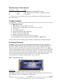
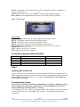
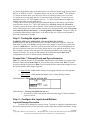
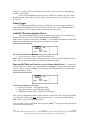
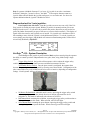
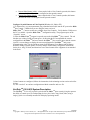
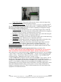
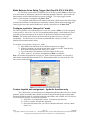
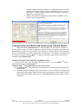
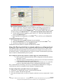
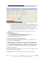
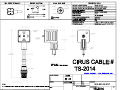
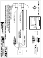
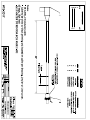
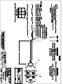
Mako
TM
(Uni-Grip 832, 816, 632, 616, 410,
Multi-Stix Trio 314, Multi-Stix Twin 210)
Operation Manual
Rev L
Page 1
6/28/2007
Copyright © 2006 by Cirus Controls, LLC. All Rights Reserved. No part of this material may be reproduced without
the express written permission of Cirus Controls LLC for each reproduction.
Limited Warranty ............................................................................................................................ 3
Revision level of this manual .......................................................................................................... 4
Package Contents ............................................................................................................................ 4
Functional Overview ....................................................................................................................... 4
Pre-Delivery System Setup Checklist ............................................................................................. 5
Step 1............................................................................................................................................... 5
Installing the control unit ................................................................................................ 5
Connecting the cabling ................................................................................................... 5
Step 2 - Testing the signal outputs .................................................................................................. 6
Step 3 – Configure the Joystick and Buttons................................................................................... 6
Safety Trigger ................................................................................................................. 7
SafeStik™ Run time Joystick Check............................................................................... 7
Uni-Grip TM 410 – System Description .......................................................................... 8
Uni-Grip TM 616 & 632 System Description................................................................... 9
Uni-Grip TM 816 & 832 System Description................................................................. 11
Multi-Stix 210 and 314 System Description................................................................. 13
Other Configuration Settings......................................................................................................... 13
LCD Screen Display: .................................................................................................... 13
LCD Screen Contrast: ................................................................................................... 13
3 Axis Joystick Test ...................................................................................................... 14
Float Function: Configuration is password protected.................................................. 14
Mode Buttons Act as Safety Trigger (Uni-Grip 616, 632, 816 & 832):....................... 15
Configure joystick in “always live” mode .................................................................... 15
Custom Joystick axis assignment – hydraulic functions only ...................................... 15
Linking Uni-Grip 6 & 8 Button with Hammerhead 12 Switch System........................ 16
Using Uni-Grip Joystick Axis to actuate switches on a Hammerhead ......................... 17
Configure Master and Slave Mako TM boxes for Uni-Grip 632 or 832......................... 18
Step 4 Set Up for Operation – Trimming ...................................................................................... 19
Instructions for Setting Trims and Button Configuration ............................................. 20
Global Trims Tab.......................................................................................................... 21
Test and Set Trims for Each Channel............................................................................................ 21
Using the PC to Identify the Minimum Voltage:.......................................................... 22
Maximum Trim Voltage ............................................................................................... 22
Using the PC to Set the Maximum Voltage:................................................................. 22
Upload and Store the Trim and Settings ....................................................................... 22
Downloading Trim and Settings – Backup Copy ......................................................... 23
Using Stored Trims and Settings – Restore Settings .................................................... 23
How to identify Firmware Revision on Installed Mako System................................... 23
Trouble Shooting Communications Ports ..................................................................................... 23
Trouble Shooting – Warning Indicators ........................................................................................ 25
Trouble Shooting – Summary Table ............................................................................................. 26
Appendix A: Spare parts list.......................................................................................................... 27
Appendix B – Glossary of Plow Control Terms............................................................................ 27
Appendix C – Additional Features/Options .................................................................................. 28
Rev L
Page 2
6/28/2007
Copyright © 2006 by Cirus Controls, LLC. All Rights Reserved. No part of this material may be reproduced without
the express written permission of Cirus Controls LLC for each reproduction.
Limited Warranty
Cirus Controls, LLC.
What and who is covered?
This warranty covers all defects in materials or workmanship in your Cirus Controls system under
normal use, maintenance and service. This warranty coverage applies only to the original owner
and is not transferable.
How long is the warranty period?
This warranty coverage runs for a period of 1 year from the date of initial installation (or 13
months from date of shipment from Cirus Controls), whichever occurs first. Replacement parts
are warranted for the remaining portion of the original warranty period or thirty (30) days from
date of shipment from our factory (whichever is greater).
How can you get service?
Cirus Controls’ obligation under this warranty is limited to repairing and/or replacing, at Cirus
Controls’ option, any part or parts that are determined, by Cirus Controls, to be defective. To be
eligible for any claim under this warranty, the owner (or Cirus authorized dealer) must return any
defective part(s) to the factory, within the applicable warranty period (as set out above).
What will we do?
Cirus Controls’ may, at its option, elect to grant adjustments in the field through an authorized
representative and may thereby elect to waive the requirement that parts be returned to Cirus
Controls’ factory. The repair or replacement of defective parts under this warranty will be made
without charge to the owner except for transportation of the part to our authorized repair location.
What is not covered under this warranty?
Cirus Controls will not assume any expense or liability for repairs made outside our plant without
our prior written consent. We are not responsible for damage to any associated equipment or
product and will not be liable for loss of profit or other special damages.
The provisions of this warranty do not apply to any product or parts which have been subject to
misuse, negligence or accident, or which have been repaired or altered outside of Cirus Controls’
factory in any way (in the judgment of Cirus Controls) so as to affect adversely its performance
or reliability. Neither does this warranty apply to normal maintenance service and parts or to
normal deterioration due to wear and exposure.
This warranty is expressly in lieu of other warranties, expressed or implied, in fact or by law,
including any implied warranty of merchantability of fitness for a particular purpose. The
remedies of repair or replacement as set forth are the only remedies under this warranty, Cirus
Controls’ disclaims any obligations or liability for loss of time, inconvenience, commercial loss
or direct consequential, special or incidental damages. This warranty is in lieu of any other
obligation or liability of Cirus Controls’ of any nature whatsoever by reason of the manufacture,
sale, lease or use of such products and Cirus Controls neither assumes, not authorizes anyone to
assume for it, any other obligation or liability in connection with such products.
Rev L
Page 3
6/28/2007
Copyright © 2006 by Cirus Controls, LLC. All Rights Reserved. No part of this material may be reproduced without
the express written permission of Cirus Controls LLC for each reproduction.
Revision level of this manual
Rev Letter
K
L
M
Date
9/12/05
3/21/06
5/30/07
Detail
Added SafeStik™, Channel Safe™ features
Added Mako indicators summary; new Mako trim images;
Yearly Update;
Cirus Controls reserves the right to make revisions and alterations to this manual from time to
time without notice.
Package Contents
A complete Mako TM control system contains the following items (note: some cables may not be included if
their interfacing option is not met):
1)
2)
3)
4)
5)
6)
7)
8)
9)
10)
Mako TM control unit;
Mako Trim TM program for the PC on a CD;
A DB-25 cable for connecting the control unit to the joystick pod;
This manual;
Power cable (MK-1003);
Remote Blast and Pass cable (MK-1004);
Auxiliary function cable (MK-1005).
Indicator wiring harness (MK-1006);
Hydraulic control cables ordered (TS-2030 or TS-2018);
Joystick Module with the ordered joysticks (Uni-Grip™ or Multi-Stix TM);
If any of these items are missing, please contact your distributor for replacement parts.
Functional Overview
The Mako TM control system is a 16 channel proportional hydraulic controller. It translates
movements from a joystick (Uni-Grip or Multi-Stix) to movements of truck implements such as
plows, hoists, blades, and wings. The closer the joystick is to center (neutral) the slower the
implement will move; the further from center the faster the implement will move. The Mako TM
system is field configurable using a PC connection. This allows the end user to tailor the speed of
each individual function or to turn on and off certain functions. An example of this would be the
ability to set the speed of the wing heel down different from the wing heel up speed or the ability
to turn off the hoist button when an Anti-Ice tank or V-box is slid into a dump body, thus
removing the ability to dump the Anti-Ice tank or V-box on the road.
Mako TM Joystick & PC Panel
Connections:
Joystick control: a DB-25 connector that runs up to the joystick pod;
Aux Inputs: 8-pin Molex connector used for digital auxiliary inputs such as hoist lockout, plow
float, wing float, or hot/low oil shutdown. (Optional cable)
Rev L
Page 4
6/28/2007
Copyright © 2006 by Cirus Controls, LLC. All Rights Reserved. No part of this material may be reproduced without
the express written permission of Cirus Controls LLC for each reproduction.
PC Port: standard PC serial connection used for field setting trims, and other configuration
options. (Optional cable)
LCD out: 4-pin phone jack used for Uni-Grip TM 616, 632, 816 & 832 dash display;
Bus A and B: used for communication between Cirus Controls products. (Optional)
Mako TM Power Panel
Connections:
PWR / GND: 4-pin Molex used for connecting power and ground to system;
HYD C: 6-pin Molex connector used for controlling a Blade;
HYD B: 8-pin Molex connector used for controlling a Wing;
HYD A: 8-pin Molex connector used for controlling a Hoist and Plow;
Remote Blast / Pass: 2-pin Molex for remoting blast and pass from Cirus’ spreaders.
Red LED: indicates power is “on”.
CPU1: indicates that processor is running.
CPU2: indicates that processor is running.
Pre-Delivery System Setup Checklist
Step 1
Step 2
Step 3
Step 4
Description
Install System and connect cables
Test the Signal Outputs
Configure the Joystick
Trim hydraulics for all axes of motion
Completed By/Date
Step 1
Installing the control unit
The blue control unit may be mounted on the floor, back wall of the truck, or underneath a seat.
When mounting the control unit, make sure the DB-25 cable coming from the arm unit will reach
the blue Mako TM plow control unit once it’s mounted. Do not mount the control unit with
either cable end facing up.
Connecting the cabling
Note: there are no installer connections needed inside the joystick pod. Modification of any
factory wiring in the joystick pod, arm unit, Mako TM unit or drilling holes in any of the
sheet metal housings voids the product (s’) warranty.
1) Verify that power is off. Connect one end of the DB-25 cable (hanging from the arm unit tube)
to the “joystick control port” on the Mako TM plow control. Tighten the threaded jackscrew
connections.
Rev L
Page 5
6/28/2007
Copyright © 2006 by Cirus Controls, LLC. All Rights Reserved. No part of this material may be reproduced without
the express written permission of Cirus Controls LLC for each reproduction.
2) Connect the hydraulic cables to the labeled ports. All cables are labeled on the sleeving with a
HYD A, or HYD B, or HYD C. Plug them into the correct port on the Mako TM blue enclosure.
3) Connect the remote blast / pass cable up to the Cirus Controls spreader (if one is present).
4) Connect the Aux input plug, and wire it to the sensors out on the truck. To turn on an aux
input there has to be +12 VDC applied to the wire. +12 VDC can be found on aux input pin 1,
and this can be used to power truck sensors.
5) Plug in the LCD out 4-pin phone plug, and mount the display on the dash in a position that
won’t block the drivers view. This is only required on a Uni-Grip TM 616, 632, 816 and 832.
6) Finally, connect the power cable to the unit. Check to make sure that the power switch is off
before connecting the power leads, and then connect power and ground to the cable. The ground
source must be direct to the battery. A chassis ground is not adequate. The power cable can
be connected either directly to the battery, as the unit is fused, or to a power circuit capable of
delivering a minimum of 10 amps.
Step 2 - Testing the signal outputs
WARNING: KEEP ALL PERSONNEL CLEAR OF MOVING PARTS!
With the truck off, turn on the system and wait 5 seconds for self-test to complete. Select the
hoist mode if system is a Uni-Grip TM and press the safety trigger or just move a joystick (if the
system is a Multi-Stix TM). Move the joystick up and check for the correct LED lighting up on
the valve junction box out by the valve body. Repeat this for every function on the truck. Once
this is complete, start the truck, and repeat. The implements should now move when each
function is selected. The speeds of each function can be tailored using the Mako Trim TM
configuration tool, which is described in the Trimming Step 4.
Channel Safe ™ External Shorts and Opens Protection
Mako ™ revision D (Serial # 05-431 and higher shipped after 9/1/05) include an external wiring
detection feature called Channel Safe ™. In event that wiring external to the Mako ™ system
develops a shorted or open circuit, Mako ™ will warn the operator when he/she attempts to move
the joystick with the safety trigger depressed.
a) Open Circuits: include broken wiring or not plugged in all the way to the hydraulic
coil;
b) Short Circuits: include damaged hydraulic coils or cables shorting to frame;
Fault Indication – Uni-Grip 616, 632, 816, 832
Fault Indication – Uni-Grip 410, Multi-Stix 210, 314
• Red and Green LED’s flash rapidly when the safety trigger is depressed and the
joystick is moved.
Step 3 – Configure the Joystick and Buttons
Joystick Damage Prevention
Joysticks can by damaged by incorrect wiring. Joysticks are installed, wired and tested at
the factory and must not be wired in the field by anyone other than a qualified technician. Do not
Rev L
Page 6
6/28/2007
Copyright © 2006 by Cirus Controls, LLC. All Rights Reserved. No part of this material may be reproduced without
the express written permission of Cirus Controls LLC for each reproduction.
“plug in” or “un-plug” either joystick harness with power on or joystick may be damaged and
warranty will be voided.
All Uni-Grip and Multi-Stix joysticks are true “Hall Effect” magnetic joysticks. When
handled properly, these joysticks will give long service since there are no “contact parts” inside
the joystick.
Safety Trigger
All Uni-Grip and Multi-Stix systems are configured with a safety trigger available to
protect against unintended movement of a device (plow, hoist etc). Cirus recommends that all
safety triggers be used as designed to achieve the maximum system safety.
SafeStik™ Run time Joystick Check
All Uni-Grip and Multi-Stix joysticks are monitored for any joystick or cable failure at
all times when power is on by a software mechanism called SafeStik ™.
In the event of a joystick or cable failure, the Mako TM system disables the hydraulic output that is
affected by the particular joystick and gives a warning to the operator:
Uni-Grip 616, 632, 816, 832
Uni-Grip 410, Multi-Stix 314 & 210
• Any joystick or axis failure: both LED’s blinks slowly;
Note: in the event of this warning, the damaged joystick (or axis) is disabled until repairs can be
made. The non-affected joystick(s) or joystick axes function normally.
Start up Self Test (and Multi-Stix Joystick Failure Identification): To identify the
failed joystick (axis), turn the power off and then on to the Mako TM to trigger the system start up
self test. After 5 seconds, the Mako TM will recognize the failed joystick (or axis), disable all
outputs and flash the LED’s:
Uni-Grip 616, 632, 816, 832
Uni-Grip 410, Multi-Stix 314 & 210:
• Plow Joystick failure: red LED blinks rapidly;
• Hoist Joystick failure: green LED blinks rapidly;
• Wing/Blade Joystick failure: both LED’s blink rapidly;
Once you have identified the failed joystick, release the “output lock” that was imposed by Mako,
by selecting the “blast” toggle once (on the blast/pass switch). This will cancel the blinking
LED’s and re-energize the functional joysticks.
Once the failed joystick (or damaged cable) is repaired, Mako TM will recognize the proper signal
and return to normal operation.
Rev L
Page 7
6/28/2007
Copyright © 2006 by Cirus Controls, LLC. All Rights Reserved. No part of this material may be reproduced without
the express written permission of Cirus Controls LLC for each reproduction.
Note: In systems with Mako firmware 2.2 or lower, if a joystick is moved to “maximum
deflection” during the 5 second “self test,” the Mako TM will recognize that movement as a
joystick failure and will disable the joystick until power is re-set on the unit. See above for
operator indication that the joystick is disabled or failed.
Diagnostics tool for 3 axis joysticks:
Uni-Grip 832, 816, 632 & 616: From the joystick test screen one can verify if the UniGrip joystick is sending its proper signals. With the joystick in its neutral position, no bars are
displayed on the screen. As you move the joystick in the positive direction you will see the bar
grows the further from neutral you get (or decrease as you move back to neutral). This display of
signal will be the same for each joystick axes of motion. If a joystick axis is bad there will be a
bar extending to max, while the joystick is in the held neutral position. To exit the joystick test
screen simply press the trigger, and the Mako will return to normal running mode, but the failed
axis will stay disabled by SafeStik™.
Uni-Grip TM 410 – System Description
The Uni-Grip TM 410 joystick is paired with the Mako TM plow control giving the operator
the ability to control up to three independent devices (plow, hoist, wing, blade) using a single
joystick.
Trigger Safety Switch: the joystick will not operate a device unless the trigger safety
switch is engaged. This safety feature prevents accidental movement of devices.
3 Selectable Device Choices: once the plow control is configured, the operator then
chooses the operating mode on the joystick by selecting one of these modes. Configuration of the
plow control allows any or all of these modes to be active or inactive, depending on configuration
settings. Not all systems will have all modes active.
No Button, Default Mode: when this mode is active, squeezing the trigger safety switch
and moving the joystick in the desired direction of motion will actuate the device
assigned to it. This mode is indicated by the absence of lit LED’s.
Red Button Mode: actuating the red button, squeezing the trigger safety switch and move
the joystick to operate this mode. When selected, red LED will light.
Green Button Mode: actuating the green button, squeezing the trigger safety switch and
moving the joystick to operate this mode. When selected, green LED will light.
Rev L
Page 8
6/28/2007
Copyright © 2006 by Cirus Controls, LLC. All Rights Reserved. No part of this material may be reproduced without
the express written permission of Cirus Controls LLC for each reproduction.
Remote Blast Button (white): when coupled with a Cirus Controls spreader, this button
activates the “Blast” function as configured on the spreader control.
Remote Pass Button (black): when coupled with a Cirus Controls spreader, this button
activates the “Pass” as configured on the spreader control.
Configure Joystick Buttons on Uni-Grip 410 (Windows 98, 2000 or XP)
1) To adjust trims, or system parameters plug a standard serial cable into the PC port on the Mako
TM
plow control. Validate that you are using the latest version of
Mako Trim TM. Current versions are available from Cirus Controls. Verify that the COM port on
the PC is available. Open the Mako Trim TM configuration utility. The program opens on the
“Joysticks” screen.
2) After the Mako Trim TM program is opened, turn on the blue Mako TM plow control. The red
bar that says waiting for link will turn green. At this point the PC has uploaded the current
configuration in the Mako TM and now controls the Mako TM plow control. (note: that the current
joystick’s screen changes to display the current configuration of the Mako TM unit you are
communicating with). Use the pull down menu for Red Button, Green Button and No Button
Default to change joystick options. You may change which button is assigned to which mode
(hoist, plow, wing, or blade) and deactivate one or more buttons if the equipment is not attached
to the truck.
3) Once buttons are configured, follow the instructions in the trimming section to trim each of the
devices.
4) Click “send cal” to send new configuration to Mako controller and save file.
Uni-Grip TM 616 & 632 System Description
The Uni-Grip TM 616 or 632 joystick is paired with the Mako TM plow control giving the operator
the ability to control up to five independent devices (plow, hoist, wing, blade, other) using a
single joystick. An externally mounted LCD displays operating modes.
Rev L
Page 9
6/28/2007
Copyright © 2006 by Cirus Controls, LLC. All Rights Reserved. No part of this material may be reproduced without
the express written permission of Cirus Controls LLC for each reproduction.
Trigger Safety Switch: The joystick will not operate a device unless the trigger safety
switch is engaged (prevents accidental movement of devices).
5 Selectable Device Choices: once the plow control is configured using Mako Trim TM,
the operator then chooses the operating mode on the joystick. Configuration of the plow control
allows any or all of these buttons to be active or inactive, depending on configuration settings.
Not all systems will have all buttons active.
No Button, Default: when this mode is active, squeezing the trigger safety switch and
moving the joystick in the desired direction of motion will actuate the device assigned to
it. When this mode is selected, it is indicated on the LCD screen.
Red Button: actuating the red button, squeezing the trigger safety switch and moving the
joystick to operate. When selected, it is indicated on the LCD.
Green Button: actuating the green button, squeezing the trigger safety switch and moving
the joystick to operate. When selected, it is indicated on the LCD.
Blue Button: actuating the blue button, squeezing the trigger safety switch and moving
the joystick to operate. When selected, it is indicated on the LCD screen.
Yellow Button: actuating the yellow button, squeezing the trigger safety switch and
moving the joystick to operate. When selected, it is indicated on the LCD.
Remote Blast Button (white): when coupled with a Cirus’ spreader, button activates “blast”.
Remote Pass Button (black): when coupled with a Cirus’ spreader, button activates the “Pass.”
Configure Joystick Buttons on Uni-Grip 616 & 632 (Windows 98, 2000 or XP).
****NOTE: WHEN CONNECTING MAKO TRIM TO A UNI-GRIP 616, 632, 816, OR 832
THE LCD MUST BE UNPLUGGED OR THE SERIAL CONNECTION MAY FAIL****
1) To adjust trims or system parameters plug a standard serial cable into the PC port on the Mako
TM
plow control. Use the latest version of Mako Trim TM. Current versions are posted on Cirus
Controls’ website. Verify that the COM port on the PC is available. Open the Mako Trim TM
configuration utility. The program opens on the “Joysticks” screen.
2) After the Mako Trim TM program is opened, turn on the blue Mako TM plow control. The red
bar that says waiting for link will turn green. At this point the PC has uploaded the current
configuration in the Mako TM and now controls the Mako TM plow control. (note: that the current
joystick’s screen changes to display the current configuration of the Mako TM unit you are
communicating with. Use the pull down menu for Red button, Green button, Blue button, Yellow
button and No Button Default to change joystick options. You may change which button is
assigned to which mode (hoist, plow, wing, or blade) and deactivate one or more buttons if the
equipment is not attached to the truck.
Rev L
Page 10
6/28/2007
Copyright © 2006 by Cirus Controls, LLC. All Rights Reserved. No part of this material may be reproduced without
the express written permission of Cirus Controls LLC for each reproduction.
3) Once buttons are configured, follow the instructions in the trim section to trim each device.
Uni-Grip TM 816 & 832 System Description
The Uni-Grip TM 816 or 832 joystick is paired with the Mako TM plow control giving the operator
the ability to control up to seven independent devices (plow, hoist, wing, blade, other) using a
single joystick. An external LCD displays operating modes.
Trigger Safety Switch: The joystick will not operate a device unless the trigger safety
switch is engaged (prevents accidental movement of devices).
7 Selectable Device Choices: once the plow control is configured using Mako Trim TM,
the operator then chooses the operating mode on the joystick. Configuration of the plow control
allows any or all of these buttons to be active or inactive, depending on configuration settings.
Not all systems will have all buttons active.
No Button, Default: when this mode is active, squeezing the trigger safety switch and
moving the joystick will actuate the device assigned to it. When this mode is selected, it
is indicated on the LCD screen.
Red Button: actuating the red button, squeezing the trigger safety switch and moving the
joystick to operate this mode. When this mode is selected, it is indicated on the LCD
screen.
Green Button: actuating the green button, squeezing the trigger safety switch and moving
the joystick to operate this mode. When this mode is selected, it is indicated on the LCD
screen.
Blue Button: actuating the blue button, squeezing the trigger safety switch and moving
the joystick to operate this mode. When this mode is selected, it is indicated on the LCD
screen.
Rev L
Page 11
6/28/2007
Copyright © 2006 by Cirus Controls, LLC. All Rights Reserved. No part of this material may be reproduced without
the express written permission of Cirus Controls LLC for each reproduction.
Yellow Button: actuating the yellow button, squeezing the trigger safety switch and
moving the joystick to operate this mode. When this mode is selected, it is indicated on
the LCD screen.
Orange Button: actuating the orange button, squeezing the trigger safety switch and
moving the joystick to operate this mode. When this mode is selected, it is indicated on
the LCD screen.
Purple Button: actuating the purple button, squeezing the trigger safety switch and
moving the joystick to operate this mode. When this mode is selected, it is indicated on
the LCD screen.
Remote Blast Button (white): when coupled with a Cirus’ spreader, this button activates “blast.”
Remote Pass Button (black): when coupled with a Cirus’ spreader, this button activates “Pass.”
Configure Joystick Buttons on Uni-Grip 816 & 832 (Windows 98, 2000 or XP).
****NOTE: WHEN CONNECTING MAKO TRIM TO A UNI-GRIP 616, 632, 816, OR 832
THE LCD MUST BE UNPLUGGED OR THE SERIAL CONNECTION MAY FAIL****
1) To adjust trims, or system parameters plug a standard serial cable into the PC port on the Mako
plow control. Use the latest version of Mako Trim TM. Current versions are posted on Cirus
Controls’ website. Verify that the COM port on the PC is available. Open the Mako Trim TM
configuration utility. The program opens on the “Joysticks” screen.
2) After the Mako Trim TM program is opened, turn on the blue Mako TM plow control. The red
bar that says waiting for link will turn green. At this point the PC has uploaded the current
configuration in the Mako TM and now controls the Mako TM plow control. (note: that the current
joystick’s screen changes to display the current configuration of the Mako TM unit you are
communicating with. Use the pull down menu for Red button, Green button, Blue button, Yellow
button, Orange button, Purple button and No Button Default to change joystick options. You may
change which button is assigned to which mode (hoist, plow, wing, or blade) and deactivate one
or more buttons if the equipment is not attached to the truck.
TM
3) Once buttons are configured, follow the instructions to trim each of the devices.
4) Click “send cal” to send new configuration to Mako controller and save file.
Rev L
Page 12
6/28/2007
Copyright © 2006 by Cirus Controls, LLC. All Rights Reserved. No part of this material may be reproduced without
the express written permission of Cirus Controls LLC for each reproduction.
Multi-Stix 210 and 314 System Description
The Multi-Stix TM 210 and 314 joystick modules are paired with the Mako TM plow
control giving the operator the ability to control up to five independent devices (plow, hoist,
wing, blade, other) using two or three mini joysticks to actuate a device.
Configure Joystick Buttons on Multi-Stix 314 & 210 (Windows 98, 2000 or XP).
1) To adjust trims, or system parameters plug a standard serial cable into the PC port on the Mako
TM
plow control. Use the latest version of Mako Trim TM. Current versions are posted on Cirus
Controls’ website. Verify that the COM port on the PC is available. Open the Mako Trim TM
configuration utility. The program opens on the “Joysticks” screen.
2) After the Mako Trim TM program is opened, turn on the blue Mako TM plow control. The red
bar that says waiting for link will turn green. At this point the PC has uploaded the current
configuration in the Mako TM and now controls the Mako TM plow control. (note: the Mako Trim
screen changes to display the configuration of the Mako TM you are communicating with).
3) From the “select joystick option menu, choose “2 HFX” for the Multi-Stix 210 or “3HFX” for
Multi-Stix 314. Then, use the other pull down menus to assign each joystick to the hydraulic
function desired and to assign top switches as desired.
4) Once joysticks are configured, follow the instructions to trim each of the devices.
5) Click “send cal” to send new configuration to Mako controller and save file.
Other Configuration Settings
LCD Screen Display:
Active mode is shown: the black box around the active function name and all enabled button
names shown in their relative position on the joystick.
LCD Screen Contrast:
To enter the screen contrast mode and joystick test mode, press the remote blast and the
remote pass buttons at the same time. The right side of the UG 616 LCD screen will display the
instructions. Press the “remote blast” key to lower the contrast or the “remote pass” key to
Rev L
Page 13
6/28/2007
Copyright © 2006 by Cirus Controls, LLC. All Rights Reserved. No part of this material may be reproduced without
the express written permission of Cirus Controls LLC for each reproduction.
increase it. When your contrast is set, press the trigger, the contrast is saved and the screen will
advance to the joystick test screen.
3 Axis Joystick Test
From the joystick test screen one can verify if the Uni-Grip joystick is sending its proper
signals. With the joystick in its neutral position, no bars are displayed on the screen. As you
move the joystick in the positive X direction you will see a bar increase the further from neutral
you get, and it will also decrease as you move back to neutral. This same display of signal will be
the same for each joystick axes of motion. If a joystick axis is bad there will be a bar extending
to max, while the joystick is in the neutral position. To exit the joystick test screen simply press
the trigger, and the Mako will return to normal running mode.
Float Function: Configuration is password protected.
In the Uni-Grip and Multi-Stix products, the “float” function is created by electrically
terminating the hydraulic “down force” on the implement and relying on the weight of the
implement to hold it down. Plow, Wing, or Blade floats can be enabled or disabled for the
system by using the Mako Trim TM “float” tab and the proper password. Float should not be
configured except by a qualified technician.
Engage Float Function: can be triggered in one of two ways.
1)
External switch that the driver must turn on and off to engage or disengage the
float (does not include wing toe float).
2)
Move the joystick to max deflection in the direction of the desired float. To
disengage the float, squeeze the trigger and move the joystick in the opposite
direction of the float (typically, move the joystick in the “up” direction).
“Wing toe” float can only be engaged using the joystick.
Display of Float Status: When float is active for an implement, operator indication is:
1)
Uni-Grip 616, 632, 816 & 832 the active float is displayed on the LCD screen,
and disappears when float is disengaged.
2)
Uni Grip 410, Multi-Stix 314 and 210:
a. Plow LED blinks once every 3 seconds when plow float is engaged;
b. Hoist LED blinks once every 3 seconds when wing toe or wing heel is
engaged.
c. Both LED’s blink once every 3 seconds when blade float is engaged.
NOTE: Once in a float mode, the Mako TM box will deliver max trim to the implement in
float until the float is removed.
Rev L
Page 14
6/28/2007
Copyright © 2006 by Cirus Controls, LLC. All Rights Reserved. No part of this material may be reproduced without
the express written permission of Cirus Controls LLC for each reproduction.
Mode Buttons Act as Safety Trigger (Uni-Grip 616, 632, 816 & 832):
For Uni-Grip systems with LCD displays (6xx or the 8xx systems), Mako TM allows you
to use the buttons as momentary contacts for controlling hydraulic functions. In this mode, the
button must be selected and held down to operate a function. The safety trigger becomes
inactive if this function is configured using Mako Trim TM.
To re-assign the mode buttons from latched connections (which require the safety trigger
to actuate the function) to mode buttons as momentary contacts (which then become their own
safety triggers since they must be held down to operate), check the box on Mako Trim TM.
Configure joystick in “always live” mode
For Uni-Grip systems with LCD displays (6xx or the 8xx systems), Mako TM can be configured
so the joystick is “always live” for one of its standard function groups. In this mode, the pistol
grip safety trigger or the buttons do not need to be depressed to actuate the mode assigned.
Caution: Use of this mode increases the chance that an operator can move a plow unintentionally. For this reason, Cirus Controls recommends that “always live mode” be left
disabled for maximum operator safety.
To configure your system in “always live” mode:
1) Open Mako Trim and check the box labeled “buttons act as trigger”
2) Select the function you wish to operate in the “always live mode” from the drop
down menu selection list titled “always live” mode.
3) Type in the label of the function you wish to appear on the screen.
4) Select “send cal,” to send new configuration to Mako TM controller.
Note: the function assigned in the “always live” mode, will always default “on” shown by a
black border around that function on the LCD. When another button is selected, the box will
move to the selected function.
Custom Joystick axis assignment – hydraulic functions only
The Custom tab is a password protected configuration table that allows the user to assign
hydraulic groups in a manner that is flexible instead of using the default groups used normally.
Selections should be made by a qualified technician only and are only available for Uni-Grip 616,
632, 816 and 832 systems. To access the selections:
1) Verify that “6 or 8 button HG system” is selected on Joysticks tab;
2) Click on “custom” tab and enter password;
3) Select the first button color you wish to customize and check “activate custom
mode,” box.
Rev L
Page 15
6/28/2007
Copyright © 2006 by Cirus Controls, LLC. All Rights Reserved. No part of this material may be reproduced without
the express written permission of Cirus Controls LLC for each reproduction.
i. Custom configure hydraulic functions: use pull down menu to select the
hydraulic function you wish to assign to a particular axis (x, y or z) on
that button. Continue making selections until all hydraulic functions are
assigned to a button and axis.
ii. Finally, click send cal to upload the configuration to the Mako TM box,
and save your configuration file.
Linking Uni-Grip 6 & 8 Button with Hammerhead 12 Switch System
When linked with a Hammerhead TM 12 Switch module, the Uni-Grip 6xx or the 8xx
joystick can have some of its buttons assigned as remote actuators of functions controlled by the
Hammerhead 12 switch accessory module. Once linked, the controlled function can be actuated
with the joystick button or with the switch on the 12 switch panel. This feature is available on the
6xx or the 8xx joystick using the Mako TM to link the particular joystick button to the function
controlled on the Hammerhead TM.
To link the functions between the Mako and HammerHead
1) Plug one end of the “Cirus Bus cable- HH-1001” into the “bus” port on Mako TM and the
other into the bus port on Hammerhead TM.
Configure Mako TM after connecting your PC to the PC port:
2) Open Mako Trim TM and select the joystick mode you are working with (6 button HG or
8 button HG).
3) Select the select the button you want to make control a remote switch by clicking the pull
down menu and selecting "Remote button" and type in the name of the function that will
be triggered by this button (same name as on the HammerHead for that switch #, such as
“Vibrator”).
Rev L
Page 16
6/28/2007
Copyright © 2006 by Cirus Controls, LLC. All Rights Reserved. No part of this material may be reproduced without
the express written permission of Cirus Controls LLC for each reproduction.
4) Click the "remote/slave" tab;
5) On the "remote/slave" tab go the remote settings for the button you selected to be a
remote switch. Now set the target ID (101-199) to match the Hammerhead TM ID.
If you haven't previously setup the Hammerhead TM yet just pick a number and write it down
for when setting up the Hammerhead TM. Note: Do not use default value of 200 or 255.
6) Set the switch you'd like to control: choose from 1 to 12. How the switch functions is
setup in the Hammerhead TM.
7) Now upload the configuration to the Mako TM box, and save you configuration
file.
Companion Hammerhead TM setup:
1) Configure all switch functions and names as you want them.
2) Match the Hammerhead TM ID to the Target ID (101-199) used in the Mako TM box.
3) Upload the configuration file to the Hammerhead TM.
Configuration of both systems is complete and functions are linked.
Using Uni-Grip Joystick Axis to actuate switches on a Hammerhead
This capability allows you to use joystick motion in a specific direction/axis to actuate switch
functions controlled by HammerHead switch controller (only available for Uni-Grip 616, 632,
816 and 832 systems). In this application, the joystick is a remote switch actuation system and
must be linked to a HammerHead system to operate.
Once configured, operate the joystick as a remote trigger for switch functions by:
1) Move joystick to maximum deflection in the configured axis/direction and then
hold for 0.5 second.
2) The linked switch (on HammerHead) will then activate in the manner defined on
the HammerHead (momentary, on/off, delay etc).
3) To turn off any switch with a latched function (on/off, delay on, etc.) return the
joystick to maximum deflection in the configured axis/direction as before.
Note: switch behavior (momentary, on/off etc) is controlled in the HammerHead. Changes to
switch behavior must be accomplished in the Hammer Configuration utility.
To begin configuration, open Mako Trim on your laptop PC:
1) Verify that “6 or 8 button HG system” is selected on Joysticks tab;
2) Click on “custom” tab and enter password;
3) Select the first button color you wish to customize and check “activate custom mode,” check
box.
Rev L
Page 17
6/28/2007
Copyright © 2006 by Cirus Controls, LLC. All Rights Reserved. No part of this material may be reproduced without
the express written permission of Cirus Controls LLC for each reproduction.
4) Custom configure switch actuation using joystick: use pull down menu to select the switch
group you wish to control with a particular joystick axis (x, y, or z). Note that each switch
group controls 2 switches (one in the plus direction, and one in the minus direction).
5)
6) Link Joystick Axis to Switches on HammerHead system.
a. Select “Switch group setup” button to assign linkage with a HammerHead system
(target ID #) and with specific switch pairs on that system. Note: Joystick movement
in the “minus direction” for the chosen axis, actuates the switch # chosen under
“switch minus.” Joystick movement in the “plus direction” for the chosen axis,
actuates the switch # chosen under “switch plus.” Any or all three joystick axes (x, y
& z) can be assigned to switch functions. Click “close” when complete.
7) Finally, click “send cal” to upload the configuration to the Mako TM box and save your
configuration file.
Companion Hammerhead TM setup:
1) Configure all switch functions and names as you want them.
2) Match the Hammerhead TM ID to the Target ID used in the Mako TM box.
3) Upload the configuration file to the Hammerhead TM.
Configuration of both systems is complete.
To electrically link the HammerHead and Mako systems,
1) Plug one end of the “Cirus Bus cable – HH-1001” into the “bus” port on Mako TM and the
other into the bus port on Hammerhead TM.
Configure Master and Slave Mako TM boxes for Uni-Grip 632 or 832
The Uni-Grip 632 & 832 systems use a pair of Mako TM boxes working as master and
slave to deliver 32 independent PWM channels. In this system, buttons on a single joystick
control PWM signals for two Mako boxes which are wired to separate hydraulic functions.
To link the two Mako TM boxes:
Plug one end of the “Cirus Bus cable- HH-1001” into the “bus” port on master Mako TM and the
other into the bus port on the slave Mako TM.
Configure Master Mako TM (after connecting your PC to the PC port on the Master):
Rev L
Page 18
6/28/2007
Copyright © 2006 by Cirus Controls, LLC. All Rights Reserved. No part of this material may be reproduced without
the express written permission of Cirus Controls LLC for each reproduction.
1) Master unit is the blue box with joystick connected to it. Select either 6 button or 8 button
modes from the select joystick option on the joystick screen on Mako Trim TM.
2) Select each of the buttons that will control the slave hydraulics by clicking the pull down
menu and selecting "slave hydraulics". For example, choose the red button to control
hydraulics whose electrical signal is coming from the slave Mako TM box.
3) Then click the "remote/slave" tab.
4) On the "remote/slave" tab, go the remote setting for the button you select to be slave
hydraulics. Set the target ID to match the slave Mako TM ID. Since you haven't setup
the slave yet, pick a number and write it down for use when setting up the slave box.
5) Select the slave mode you'd like to control. Your choices are red, green, blue, and yellow.
The colors refer to the 4 separate hydraulic groups on the slave Mako TM that are accessed
through the master Mako TM. The color serves as the name of each particular group
(unique group ID). Color names are used since any of these groups can be assigned to
control any of the hydraulic functions on the truck.
6) Now upload the configuration to the Mako TM box by choosing the “send cal” tab, and
save you configuration file to your PC.
Configure Slave Mako TM (after connecting your PC to the PC port on the Slave):
1) Open Mako Trim. On the joystick tab page, under “select joystick option,” choose "slave
mode".
2) Select the mode you'd like to setup. It must match the color of the mode selected in the
master. The system defaults to Hoist (red), Plow (green), Wing (blue) and Blade
(yellow). Now choose the hydraulic function you wish to assign to each color. Make all
unused modes inactive. It is possible to make the mode color and its linked button color
the same, but is not required since they do not functionally correlate unless you choose to
make it so.
3) Set the Mako TM ID of this box to match the Target ID set in the Master Mako TM box.
4) Upload new configuration by pressing “send cal”, and save the config. file to your PC.
Note: linking the Mako TM boxes is complete, but each box must still be trimmed following the
instructions below.
Step 4 Set Up for Operation – Trimming
Overview of Trims for Proportional Control of Motion (Feathering)
Setting trims is the process of setting minimum and maximum signal voltages for the valve coil
that result in a fine-tuning of the range of proportional control available to the operator.
Proportional control of motion allows the operator to move the control joystick a small amount to
control low-speed movement and a large amount to control high-speed movement. When
properly set, the operator can “feather” the control joystick and move the implement (plow, dump
body) at the rate of speed that is appropriate to the task at hand for maximum safety and
efficiency.
Trims can be set at the outer limits of the electro-hydraulic system’s capability for proportional
control of motion or they can be narrowed to a tighter range of control.
The larger the
difference in voltage between the minimum and maximum settings, the larger the range of
movement of the control joystick and the finer degree of proportional control of motion is
available to the operator.
Minimum Trim: the minimum signal voltage delivered to the coil necessary to result in enough
flow of hydraulic fluid to begin to move the implement selected. This voltage value will vary
based on the valve coil in use, the size of the hydraulic system, the size of the hydraulic cylinder
Rev L
Page 19
6/28/2007
Copyright © 2006 by Cirus Controls, LLC. All Rights Reserved. No part of this material may be reproduced without
the express written permission of Cirus Controls LLC for each reproduction.
and the weight of the implement (dump body, plow, wing etc). Minimum settings can only be
determined at operating engine RPM’s with hydraulic fluid warmed to its normal operating
temperature.
Maximum Trim: the maximum signal voltage delivered to the coil necessary to result in enough
flow of hydraulic fluid to reach the maximum speed of motion of the implement intended. This
voltage value will vary based on the valve coil in use, the size of the hydraulic system, the size of
the hydraulic cylinder and the weight of the implement in use (dump body, plow, wing etc) and is
normally pre-set at the factory.
Typical Settings (largest difference between min and max settings): choosing these settings
results in the largest amount of proportional control available for that hydraulic system. The
operator will be able to make large and small adjustments to speed of motion by moving the
control joystick a corresponding amount.
Bang /Bang Control (On/Off): Set the minimum and maximum trim voltage levels at 12V.
Zero proportional control of speed is available at this setting.
Other Setting Combinations: because each implement has different performance
characteristics, setting trims uniquely for each one will create the best sense of control for both
safety and efficiency.
Instructions for Setting Trims and Button Configuration
In order for a Mako TM plow control system to proportionally move implements the system may
have to be trimmed. The unit comes factory set for a variety of different coils, which allows the
unit to run without changes. However if some of the implements don’t move as desired, they can
be adjusted by setting new min and max trim settings via the Mako Trim TM configuration
program which can be found on the CD accompanying the system user manual. Mako Trim TM is
compatible with personal computers (PC) or laptops running Windows 2000 or XP operating
system.
1) To adjust trims, or system parameters plug a standard serial cable into the PC port on the Mako
plow control. Validate that you are using the latest version of Mako Trim TM. Current
versions are posted on Cirus Controls’ website. Verify that the COM port on the PC is available.
Open the Mako Trim TM configuration utility. The program opens on the “Joysticks” screen.
TM
Note: “Custom and Float” tabs are only accessible with password and should not be
changed except by a qualified technician.
Rev L
Page 20
6/28/2007
Copyright © 2006 by Cirus Controls, LLC. All Rights Reserved. No part of this material may be reproduced without
the express written permission of Cirus Controls LLC for each reproduction.
2) After the Mako Trim TM program is opened, turn on the blue Mako TM plow control. The red
bar that says waiting for link will turn green. At this point the PC has uploaded the current
configuration in the Mako TM and now controls the Mako TM plow control. (note that the current
joystick’s screen changes to display the current configuration of the Mako TM unit you are
communicating with. Use the “joysticks screen” to change joystick options, change which button
is assigned to which mode (hoist, plow, wing, or blade), and for deactivating buttons if the
equipment is not attached to the truck.
Global Trims Tab
This screen is used for setting the coil type, coil frequency, and setting all the trims to be the same
with the global trim sliders. Use the slider to select the voltage desired and then selects “set all
trims” to apply those values to all channels on the system.
Test and Set Trims for Each Channel
If you wish to set trims individually for each implement, use the next 4 tabs to do so for
all the axes of motion. To set the hoist trims simply click the hoist tab.
Rev L
Page 21
6/28/2007
Copyright © 2006 by Cirus Controls, LLC. All Rights Reserved. No part of this material may be reproduced without
the express written permission of Cirus Controls LLC for each reproduction.
Using the PC to Identify the Minimum Voltage:
Caution, the hoist will move, keep all personnel clear before beginning.
1)With the truck running, move the hoist up slider up in 0.1 volt increments. Each mouse click
will move the value up 0.1V and the displayed value will change.
2) After each increase press and hold the “TEST MIN” button. This will tell the Mako TM box to
move the hoist at the set level. It is not necessary to move the joystick.
3) If the hoist doesn’t move, move the slider and repeat the process until the hoist just starts to
move. “Ideal” minimum voltage is the point at which the hoist barely moves when you hit the
“test min” button.
4) To set the next channel independently, select the tab for the implement you want to change and
repeat this process.
Maximum Trim Voltage
The maximum voltage setting is pre-set at the factory to match the valve coil in use on this
system. The max trim can be reduced below the pre-set level to (from full on to barely moving)
by moving the max slider downward. This type of “lowered maximum” is used to balance the
speed of the wing toe and wing heel or to lower the speed of a “lighter” implement to keep it from
banging when run at top speed. The procedure is the same for the plow, wing, and blade tabs.
Increasing the maximum voltage will only increase speed of motion up to the maximum capacity
of the hydraulic system, increasing above that point will not increase the speed of the system.
Using the PC to Set the Maximum Voltage:
Caution, the hoist will move, keep all personnel clear before beginning.
1) With the truck running, move the “hoist up max slider” down in 0.1 volt increments.
Each mouse click will move the value down 0.1V and the displayed value will change.
2) After each increase press and hold the “TEST MAX” button. This will tell the Mako TM to
move the hoist at the set level. Do not move the joystick.
3) Final setting will depend on the desired maximum speed you seek. Observe the speed at
several Max settings and choose the speed that meets your needs.
4) To set the next channel independently, select the tab for the implement you want to change and
repeat this process.
Upload and Store the Trim and Settings
Once all the trims are set to the users liking, they must uploaded to the Mako TM box by clicking
the “Send Cal” button.
Rev L
Page 22
6/28/2007
Copyright © 2006 by Cirus Controls, LLC. All Rights Reserved. No part of this material may be reproduced without
the express written permission of Cirus Controls LLC for each reproduction.
NOTE: TRIMS ARE NOT UPDATED OR SAVED IN THE SYSTEM UNTIL THE SEND
CAL BUTTON IS PRESSED.
This file can also be saved on the PC by clicking the file menu and saving the configuration.
When the PC is connected to a printer, the numerical values can be printed for your records.
Downloading Trim and Settings – Backup Copy
In the event you wish to download the trim setting from a Mako TM box. Connect the PC as
before, and simply press the “Get Cal” button. Save the new file on your PC.
Using Stored Trims and Settings – Restore Settings
You may use a settings file stored on your PC to upload an existing configuration to a new (or
repaired) Mako TM plow control. Connect the PC to the Mako TM plow control as before and
click on “Send Cal.” The Mako TM plow control now is configured with the stored file.
How to identify Firmware Revision on Installed Mako System
The Mako controller indicates the current revision of firmware installed during each power up
cycle of the system. For troubleshooting purposes, knowing the revision of the firmware in your
system will help the technician identify needed updates:
1) Uni-Grip 616, 632, 816, 832 – with external LCD. Press blast/pass buttons
simultaneously (white and black buttons on joystick) and observe “contrast screen”
on the right half of the display. At the bottom on that section will list the firmware
revision (eg “Version 2.2”)
2) Uni-Grip 410, Multi-Stix 414, 314 and 210. Observe red and green LED during
power up.
a. Green LED will blink the number of times for the “major revision number.”
(2 blinks = revision 2.)
b. Red LED will blink the number of times for the “minor revision number.” (3
blinks = revision 0.3)
In this example, the system revision = 2.3.
Units with firmware below 2.0 do not display firmware version on the system. Contact your
service representative for questions on earlier models.
Trouble Shooting Communications Ports
Rev L
Page 23
6/28/2007
Copyright © 2006 by Cirus Controls, LLC. All Rights Reserved. No part of this material may be reproduced without
the express written permission of Cirus Controls LLC for each reproduction.
Red Bar: indicates serial port issue on
PC in use; Close other programs using
that serial port; Contact IT department;
Blue Bar: serial port ok, check cable and
serial port number; Change to another serial
port and try connection again;
Green Bar: connected and listening,
see progress bar for status of data transfer;
Red bar during download: download fail;
Reset connection & cycle Mako power;
Rev L
Page 24
6/28/2007
Copyright © 2006 by Cirus Controls, LLC. All Rights Reserved. No part of this material may be reproduced without
the express written permission of Cirus Controls LLC for each reproduction.
Trouble Shooting – Warning Indicators
Multi-Stix 210 & 314 Module
Uni-Grip 410 Stick
Uni-Grip 616 & 816 Display
Warnings
Cause
Correction
Both LED’s blink slowly or “joystk
error” on LCD display;
•Output disabled due to joystick
axis failure or joystick unplugged;
•Joystick moved during start up
sequence (pseudo failure);
•Verify wiring or replace joystick;
•Replace DB-25 cable to blue box;
•Cycle power on Mako Blue box,
Single LED’s in nose pod blink
slowly (Multi-Stix - only after
system power up);
Red LED Blinks - Plow stick fail;
Green LED Blink- hoist stick fail;
Both Blink – Wing/Blade stick fail;
• Cycle power on Mako Blue box,
do not move joystick for 5 seconds;
• Replace DB-25 cable to blue box;
• Replace joystick
Both LED’s in nose pod blink fast
(Uni-Grip 410, MS 210, 314) or
Output fault shows on LCD.
Only occurs when safety trigger is
depressed and stick is moved.
External Wiring failure (short or
open);
Troubleshoot wiring to hydraulic
coil looking for opens and/or shorts;
Verify that all connections are
plugged in completely;
do not move joystick for 5 seconds;
Mako TM CPU Module
Warnings
Cause
Correction
Lights CPU 1 & CPU 2 Blink
a) Communications error between
components (blue & green box);
a) Reset power on Mako;
b) Replace Mako system;
Rev L
Page 25
6/28/2007
Copyright © 2006 by Cirus Controls, LLC. All Rights Reserved. No part of this material may be reproduced without
the express written permission of Cirus Controls LLC for each reproduction.
Trouble Shooting – Summary Table
Complaint
Set Up
Power Isn’t On
Cause (s)
Correction (s)
a) Master Power Off;
b) Fuse is blown;
c) Bad Power or Ground connection;
a) Turn on power;
b) Replace Fuse
c) Verify power/ground connections.
Mako cuts out or acts strange;
Low power supply voltage from truck
battery/alternator;
Minimum truck voltage must be >
12.0 volts;
Plow/Wing/Blade or Hoist Doesn’t
Move
a) PTO not engaged;
b) Hydraulics not functioning;
a) Engage PTO;
b) Verify Hydraulics: actuate plow or
hoist; manually operate using manual
over-ride on valve;
c) Check LED at coil connection and
at valve junction box; Repair cable
connections;
d) Check wiring connections;
e) “Power up” joystick self test;
Repair/replace indicated joystick.
c) Electrical connection failure;
d) Mako power off;
e) Joystick malfunction;
System doesn’t respond to joystick
(initial setup)
a) Mako not configured to match the
joystick system in truck;
b) one or more joysticks have failed
and Mako has canceled the output
signal to protect the hydraulic system;
a) Use Mako Trim to configure the
system to match the joystick installed
in the truck.
b) See Joystick Safety section in this
manual to diagnose which joystick has
failed;
Implement (plow) moves without
actuating joystick;
a) Output signal on at all times;
a) Verify joystick cable is plugged in
properly on both ends;
b) Verify that individual joysticks are
plugged into joystick PCB in arm unit.
c) Joystick was damaged by incorrect
wiring and must be replaced.
Lights CPU 1 & CPU 2 Blink
a) Communications error;
a) Reset power on Mako;
b) Replace Mako system;
Display/LED’s
LCD too dark or too light (Uni-Grip
616 only)
Contrast setting needs to be changed;
Simultaneously push Blast and Pass
buttons to enter contrast mode. Then
push blast to raise, pass to lower.
LCD Display Changes
LCD is Blank or Locks Up
Some variation is normal
CPU Lock Up;
LCD Failure;
LCD Cable Failure
Re-set contrast as needed;
a) Master System Reset (power);
b) Replace LCD;
c) Replace LCD Cable;
Both LED’s in nose pod blink slowly
or “joystk error” on LCD display
Both LED’s in nose pod blink fast
(Uni-Grip 410, MS 210, 314 only)
Joystick failure
Replace joystick
External Wiring failure (short or
open)
Trouble shoot wiring to hydraulic coil
looking for opens and shorts;
Single LED’s in nose pod blink
slowly
Red LED Blinks - Plow joystick fail
Green LED Blink- hoist joystick fail
Both Blink: wing stick fail
Replace joystick;
Replace joystick;
Replace joystick;
Rev L
Page 26
6/28/2007
Copyright © 2006 by Cirus Controls, LLC. All Rights Reserved. No part of this material may be reproduced without
the express written permission of Cirus Controls LLC for each reproduction.
Appendix A: Spare parts list
Uni-Grip 832, 616,410 (Mako Style)
UG-832M-NP-0
Mako UG 816 or 832 nose piece w/ Joystick no indicators
000862
UG 816 or 832 Joystick (8 button)
030162
UG 616, 632, 816 & 832 M LCD display unit
020281
16' LCD cable
UG-616M-NP-0
Mako UG 616 nose piece w/ Joystick no indicators
000865
UG 616 or 632 Joystick (6 button)
020281
16' LCD cable
UG410M-NP-0
Mako UG-410 nose piece w/ Joystick - no indicators
000864
UG 410 Joystick ( 4 button)
Multi-Stix 210 and 314 ( Mako Style)
000848
HFX Dual Axis Joystick
000845
HFX Single Axis Joystick
001032
Parts that are Common to both
Mako Uni-Grip and Multi-Stix
Systems
Printed Lens for Sprague switch
030188-Rev B
Mako CPU in blue x tech enclosure w/ Mako Trim
020513
DB25 Male to Female Cable - 10' length
HH-1001
Cirus Bus cable (from Mako to HammerHead)
MK-1003
Mako Power Cable
MK-1004
Mako Remote Blast/Pass cable
MK-1005
Mako Aux inputs cable
MK-1006
Mako indicator lights cable
IP 68 Valve Junction Box Parts
TS-2030
6 (active) Port Junction Box
TS-2018
4 (active) Port Junction Box
TS-2010
24" Pigtail with Weatherpak termination (2 pin, tower half)
TS-2011
24" Pigtail with AMP Jr termination (2 pin)
TS-2012
24" Pigtail with AMP termination (2 pin)
TS-2013
24" Pigtail with C2 (ITT Canon)Termination
TS-2014
24' Pigtail with DIN Terminations
TS-2016
24' Pigtail with 2-m12 to DIN Termination
TS-2017
24' Pigtail with Metrapack Termination
Appendix B – Glossary of Plow Control Terms
Uni-GripTM: Single joystick system for controlling plowing systems.
Multi-StixTM : Multiple joystick system for controlling plowing systems.
Mako TM: Electronics backpack housing CPU and interconnections.
Mako Trim TM: Windows compatible software for configuration of plow control system.
Proportional Control: the ability to control motion of a plow in a smooth, feathering manner
from slowest to fastest speed of motion possible for a given hydraulic set up. The closer the
joystick is to center (neutral) the slower the implement will move; the further from center the
faster the implement will move.
Rev L
Page 27
6/28/2007
Copyright © 2006 by Cirus Controls, LLC. All Rights Reserved. No part of this material may be reproduced without
the express written permission of Cirus Controls LLC for each reproduction.
Bang-Bang Control: the ability to control motion of a plow as either fully on or fully off
resulting in a single speed of motion determined by the hydraulic system (no operator control).
Minimum Trim: the minimum signal voltage delivered to the coil necessary to result in enough
flow of hydraulic fluid to begin to move the implement selected.
Maximum Trim: the maximum signal voltage delivered to the coil necessary to result in enough
flow of hydraulic fluid to reach the maximum speed of motion of the implement intended.
Float Function: the automatic removal of hydraulic down pressure on a plow, wing or blade
using the joystick control. Allows plow to “float” on the road with only its own weight pushing
down.
Active Mode: the joystick mode that has been selected by the operator, allowing him to move
the device assigned to that mode.
Button Assignment: the device to which that joystick button is assigned. Example: the green
button is assigned to operate the plow. Button assignments may only be changed by reconfiguring the Mako TM controller.
No Button Mode: the joystick control mode that does not require a button to be pushed. When
assigned to a device, this mode operates without pushing one of the joystick buttons. Device
movement is possible after depressing the joystick safety trigger.
Joystick Interconnection Drawing
Use this drawing of the Joystick board and the table below to verify joysticks are plugged
into correct ports (or follow the instructions included in Mako Trim for Multi-Stix units)
Appendix C – Additional Features/Options
HLSW100-MK
ABU100
Hoist Limit Sensor with Keyswitch
Auto Blade Up when truck is backing up
Rev L
Page 28
6/28/2007
Copyright © 2006 by Cirus Controls, LLC. All Rights Reserved. No part of this material may be reproduced without
the express written permission of Cirus Controls LLC for each reproduction.
Rev L
Page 29
6/28/2007
Copyright © 2006 by Cirus Controls, LLC. All Rights Reserved. No part of this material may be reproduced without
the express written permission of Cirus Controls LLC for each reproduction.