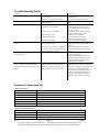
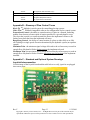
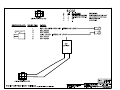
1
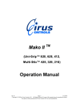
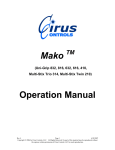
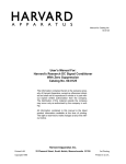
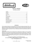
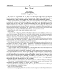
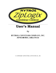
Black Tip
TM
(BT 108, BT 210, BT 310)
Operation Manual
Rev F
Page 1
1/21/2010
Copyright © 2010 by Cirus Controls, LLC. All Rights Reserved. No part of this material may be
reproduced without the express written permission of Cirus Controls LLC for each reproduction.
Limited Warranty ............................................................................................................................ 3
Revision level of this manual .......................................................................................................... 4
Package Contents ............................................................................................................................ 4
Functional Overview ....................................................................................................................... 4
Pre-Delivery System Setup Checklist ............................................................................................. 5
Step 1- Installing the control unit .................................................................................................... 5
Connecting the cabling ................................................................................................... 5
Step 2 - Testing the signal outputs .................................................................................................. 6
Step 3 – Configure the Joystick ....................................................................................................... 6
Joystick Protection and Failure Diagnosis ...................................................................... 6
System Configuration ..................................................................................................... 6
Step 4 Set Up for Operation – Trimming ........................................................................................ 7
Instructions for Setting Trims ......................................................................................... 7
Global Trims Tab ............................................................................................................ 8
Test and Set Trims for Each Channel .............................................................................................. 9
Using the PC to Identify the Minimum Voltage: ............................................................ 9
Maximum Trim Voltage ................................................................................................. 9
Using the PC to Set the Maximum Voltage: ................................................................... 9
Upload and Store the Trim and Settings ....................................................................... 10
Downloading Trim and Settings – Backup Copy ......................................................... 10
Using Stored Trims and Settings – Restore Settings .................................................... 10
Optional Hoist Limit with optional override or lockout ................................................................ 10
System Self-Diagnostics and Troubleshooting.............................................................................. 11
Joystick Check during Startup ...................................................................................... 11
Joystick failure during operation (SafeStik™) – Blinks Slow ...................................... 11
Shorted or Open Circuit on Output channels – Blinks Fast .......................................... 11
Trouble Shooting Guide ................................................................................................................ 12
Appendix A: Spare parts list ......................................................................................... 12
Appendix B – Glossary of Plow Control Terms ........................................................... 13
Appendix C – Standard and Optional System Drawings .............................................. 13
Rev F
Page 2
1/21/2010
Copyright © 2010 by Cirus Controls, LLC. All Rights Reserved. No part of this material may be
reproduced without the express written permission of Cirus Controls LLC for each reproduction.
Limited Warranty
Cirus Controls, LLC.
What and who is covered?
This warranty covers all defects in materials or workmanship in your Cirus Controls system under
normal use, maintenance and service. This warranty coverage applies only to the original owner
and is not transferable.
How long is the warranty period?
This warranty coverage runs for a period of 1 year from the date of initial installation (or 13
months from date of shipment from Cirus Controls), whichever occurs first. Replacement parts
are warranted for the remaining portion of the original warranty period or thirty (30) days from
date of shipment from our factory (whichever is greater).
How can you get service?
Cirus Controls’ obligation under this warranty is limited to repairing and/or replacing, at Cirus
Controls’ option, any part or parts that are determined, by Cirus Controls, to be defective. To be
eligible for any claim under this warranty, the owner (or Cirus authorized dealer) must return any
defective part(s) to the factory, within the applicable warranty period (as set out above).
What will we do?
Cirus Controls’ may, at its option, elect to grant adjustments in the field through an authorized
representative and may thereby elect to waive the requirement that parts be returned to Cirus
Controls’ factory. The repair or replacement of defective parts under this warranty will be made
without charge to the owner except for transportation of the part to our authorized repair location.
What is not covered under this warranty?
Cirus Controls will not assume any expense or liability for repairs made outside our plant without
our prior written consent. We are not responsible for damage to any associated equipment or
product and will not be liable for loss of profit or other special damages.
The provisions of this warranty do not apply to any product or parts which have been subject to
misuse, negligence or accident, or which have been repaired or altered outside of Cirus Controls’
factory in any way (in the judgment of Cirus Controls) so as to affect adversely its performance
or reliability. Neither does this warranty apply to normal maintenance service and parts or to
normal deterioration due to wear and exposure.
This warranty is expressly in lieu of other warranties, expressed or implied, in fact or by
law, including any implied warranty of merchantability of fitness for a particular purpose.
The remedies of repair or replacement as set forth are the only remedies under this
warranty; Cirus Controls’ disclaims any obligations or liability for loss of time,
inconvenience, commercial loss or direct consequential, special or incidental damages.
This warranty is in lieu of any other obligation or liability of Cirus Controls’ of any
nature whatsoever by reason of the manufacture, sale, lease or use of such products and
Cirus Controls neither assumes, not authorizes anyone to assume for it, any other
obligation or liability in connection with such products.
Rev F
Page 3
1/21/2010
Copyright © 2010 by Cirus Controls, LLC. All Rights Reserved. No part of this material may be
reproduced without the express written permission of Cirus Controls LLC for each reproduction.
Revision level of this manual
Rev Letter
Date
Detail
A
7/6/05
Initial Release
B
10/11/05
SafeStik, Channel Safe details added.
C
8/14/06
Hoist limit function;
D
4/27/07
Hoist lockout and over-ride capability added
E
3/9/09
BT210 added
F
1/19/10
BT310 added
Cirus Controls reserves the right to make revisions to this manual without notice.
Package Contents
A complete Black Tip TM control system contains the following items:
1) Black Tip TM control unit;
2) Mako Trim TM program for the PC on a CD;
3) This manual;
4) Power cable;
5) Hydraulic control cables ordered;
6) Switches and Indicator wiring harness;
If any of these items are missing, please contact your distributor for replacement parts.
Functional Overview
The Black Tip TM control system is a 10 channel proportional hydraulic controller. It
translates movements from a joystick(s) to movements of truck implements such as
plows, hoists and hook lifts. The closer the joystick is to center (neutral) the slower the
implement will move; the further from center the faster the implement will move. The
Black Tip TM system is field-configurable using a PC connection. This allows the end
user to tailor the speed of each individual function or to turn on and off certain functions.
For example, set the speed of the “plow down” different from the “plow up” speed.
Black Tip TM Top View (Shown with optional Dual Spread spreader control)
Backlighting “on”: indicates power is on to the system.
Rev F
Page 4
1/21/2010
Copyright © 2010 by Cirus Controls, LLC. All Rights Reserved. No part of this material may be
reproduced without the express written permission of Cirus Controls LLC for each reproduction.
Black Tip TM Cable Connections (see drawing for detail at end of manual)
Connections:
BT 1001: 10-pin Wago (orange) connector used for inputs and outputs to switches and
indicators.
PC Port: standard PC serial connection used for field setting trims and other configuration
options. (Optional cable)
PWR / GND: 4-pin Molex used for connecting power and ground to system (Standard cable);
Hook: Two, (2 pin) Molex connector for hydraulics output for hook lift (optional cable);
Hook Left / Right: 2-pin Molex connector used for hydraulic outputs for hook in/out, or wide out
plow cylinders. Cables sold separately.
BT HYD: 10-pin Molex connector used for controlling a Hoist, Plow, Auger and Spinner (for EZ
Spread, Spread DR and Dual Spread); TS-2031 included with system.
Double Acting Float: 2 pin Molex connector used for controlling dump valve for plow lift.
Cables ordered separately.
Cartridge Valve: 2 pin Molex connectors used for controlling system unloader valve. Cables
ordered separately.
Auger, Spinner, Pre-wet: 2 pin Molex connectors for hydraulic outputs for spreader (auger
reverse and pre-wet). Cables ordered separately.
Aux Input: input port for hoist limit and other sensors, optional cable required
Speedo Port: 4 pin Molex connector for TS-2004 cable for use with Ground Speed Oriented
controllers (optional).
Sensor Port: 6 pin Molex connector for use with TS 2000 sensor input cable system or Hoist
lockout key switch. Optional cable required.
Pre-Delivery System Setup Checklist
Step 1
Step 2
Step 3
Step 4
Description
Install System and connect cables
Test the Signal Outputs
Configure the Joystick
Trim hydraulics for all axes of
motion
Completed By/Date
Step 1- Installing the control unit
The Black Tip TM control unit may be mounted on a pedestal using the PEM nuts provided on the
base of the unit or inserted into the optional padded console for a bench seat. Do not mount the
control unit with the “cable end” facing up.
Connecting the cabling
Note: Modification of any factory wiring in the joystick pod, arm unit, Black Tip TM unit or
drilling holes in any of the sheet metal housings voids the product warranty.
1) Verify that power switch is off. Connect the hydraulic cables to the labeled ports. Cable is
labeled on the sleeve with TS 2031.
2) Connect the orange “Wago” input plug and wire it to the systems on truck using BT-1001.
3) Finally, connect the power cable (MK 1003) to the unit. Check to make sure that the power
switch is off before connecting the power leads, and then connect power and ground to the cable.
The ground source must be direct to the battery. A chassis ground is not adequate. The
power cable can be connected either directly to the battery, as the unit is fused, or to a power
circuit capable of delivering a minimum of 10 amps.
Rev F
Page 5
1/21/2010
Copyright © 2010 by Cirus Controls, LLC. All Rights Reserved. No part of this material may be
reproduced without the express written permission of Cirus Controls LLC for each reproduction.
Step 2 - Testing the signal outputs
WARNING: KEEP ALL PERSONNEL CLEAR OF MOVING PARTS!
With the truck off, turn on the system and wait 5 seconds for self-test to complete. Move a
joystick on the Black Tip TM. Move the joystick up and check for the correct LED lighting up on
the valve junction box out by the valve body. Repeat this for every function on the truck. Once
that is complete, start the truck, and repeat. The implements should now move when each
function is selected. The speeds of the functions can be tailored using the Mako Trim TM
configuration tool, which is described in the Trimming step.
Step 3 – Configure the Joystick
Joystick Protection and Failure Diagnosis
All Black Tip TM joysticks are true “Hall Effect” magnetic joysticks. When handled
properly, these joysticks will give long service since there are no “contact parts” inside.
Joystick Damage Prevention: Joysticks can by damaged by incorrect wiring.
Joysticks are installed, wired and tested at the factory and must not be touched in the field by
anyone other than a qualified technician. See Appendix C for plug in locations.
Do not “plug in” or “un-plug” either joystick harness with power on or joystick will be
damaged and warranty will be voided.
System Configuration
1) To adjust trims, or system parameters plug a standard serial cable into the PC port on the Black
Tip TM plow control. Use the latest version of Mako Trim TM. Current versions are posted on
Cirus Controls’ website. Verify that the COM port on the PC is available. Open the Mako Trim
TM
configuration utility. The program opens on the “Joysticks” screen.
2) After the Mako Trim TM program is opened, turn on the Black Tip TM plow control. The red
bar that says waiting for link will turn green. At this point the PC has uploaded the current
configuration in the Black Tip TM and now controls the Black Tip TM plow control. (Note: that the
current joystick’s screen changes to display the current configuration of the Black Tip TM
Rev F
Page 6
1/21/2010
Copyright © 2010 by Cirus Controls, LLC. All Rights Reserved. No part of this material may be
reproduced without the express written permission of Cirus Controls LLC for each reproduction.
3) From the system mode menu, use the other pull down menus to assign each joystick to the
hydraulic function desired and use the check boxes to assign top switches as desired.
4) Once joysticks are configured, follow instructions in the trimming section to trim each device.
5) Click “send cal” to send new configuration to Black Tip controller and save the file.
Step 4 Set Up for Operation – Trimming
Overview of Trims for Proportional Control of Motion (Feathering)
Setting trims is the process of setting minimum and maximum signal voltages for the valve coil
that result in a fine-tuning of the range of proportional control available to the operator.
Proportional control of motion allows the operator to move the control joystick a small amount to
control low-speed movement and a large amount to control high-speed movement. When
properly set, the operator can “feather” the control joystick and move the implement (plow, dump
body) at the rate of speed that is appropriate to the task at hand for best safety and efficiency.
Trims can be set at the outer limits of the electro-hydraulic system’s capability for proportional
control of motion or they can be narrowed to a tighter range of control. The larger the
difference in voltage between the minimum and maximum settings, the larger the range of
movement of the control joystick and the finer degree of proportional control of motion is
available to the operator.
Minimum Trim: the minimum signal voltage delivered to the coil necessary to result in enough
flow of hydraulic fluid to begin to move the implement selected. This voltage value will vary
based on the valve coil in use, the size of the hydraulic system, the size of the hydraulic cylinder
and the weight of the implement (dump body, plow, wing etc). Minimum settings can only be
determined at operating engine rpm's with hydraulic fluid warmed to its operating temperature.
Maximum Trim: the maximum signal voltage delivered to the coil necessary to result in enough
flow of hydraulic fluid to reach the maximum speed of motion of the implement intended. This
voltage value will vary based on the valve coil in use, the size of the hydraulic system, the size of
the hydraulic cylinder and the weight of the implement in use (dump body, plow, wing etc) and is
normally pre-set at the factory.
Typical Settings (largest difference between min and max settings): choosing these settings
results in the largest amount of proportional control available for that hydraulic system. The
operator will be able to make large and small adjustments to speed of motion by moving the
control joystick a corresponding amount.
Bang /Bang Control (On/Off): Set the minimum and maximum trim voltage levels at 12V.
Zero proportional control of speed is available at this setting.
Other Setting Combinations: because each implement has performance characteristics, setting
trims uniquely for each one will create the best sense of control for both safety and efficiency.
Instructions for Setting Trims
In order for a Black Tip TM plow control system to proportionally move implements the system
may have to be trimmed. The unit comes factory set for a variety of different coils, which allows
the unit to run without changes. However if some of the implements don’t move as desired, they
can be adjusted by setting new min and max trim settings via the Mako Trim TM configuration
program which can be found on the CD accompanying the system user manual. Mako Trim TM is
Rev F
Page 7
1/21/2010
Copyright © 2010 by Cirus Controls, LLC. All Rights Reserved. No part of this material may be
reproduced without the express written permission of Cirus Controls LLC for each reproduction.
compatible with personal computers (PC) or laptops running Windows 2000, XP or Vista
operating system.
1) To adjust trims, or system parameters plug a standard serial cable into the PC port on the Black
Tip TM plow control. Validate that you are using the latest version of Mako Trim TM. Current
versions are posted on Cirus Controls’ website. Verify that the COM port on the PC is available.
Open the Mako Trim TM configuration utility. The program opens on the “Joysticks” screen.
2) After the Mako Trim TM program is opened, turn on the blue Black Tip TM plow control. The
red bar that says waiting for link will turn green. At this point the PC has uploaded the current
configuration in the Black Tip TM and now controls the Black Tip TM plow control.
Global Trims Tab
Rev F
Page 8
1/21/2010
Copyright © 2010 by Cirus Controls, LLC. All Rights Reserved. No part of this material may be
reproduced without the express written permission of Cirus Controls LLC for each reproduction.
This screen is used for setting the coil type, coil frequency, and setting all the trims to be the same
with the global trim sliders. Use the slider to select the voltage desired and then selects “set all
trims” to apply those values to all channels on the system.
Test and Set Trims for Each Channel
If wish to set trims individually for each implement, use the next 2 tabs to do so for all the axes of
motion. To set the hoist trims simply click the hoist/hook tab.
Using the PC to Identify the Minimum Voltage:
Caution, the hoist will move, keep all personnel clear before beginning.
1) With the truck running, move the hoist up slider up in 0.1 volt increments. Each mouse click
will move the value up 0.1V and the displayed value will change.
2) After each increase press and hold the “TEST MIN” button. This will tell the Black Tip TM box
to move the hoist at the set level. It is not necessary to move the joystick.
3) If the hoist doesn’t move, move the slider and repeat the process until the hoist just starts to
move. “Ideal” min. voltage is the point at which the hoist barely moves with “test min.”
4) To set the next channel independently, select the tab for the next implement and repeat.
Maximum Trim Voltage
The maximum voltage setting is pre-set at the factory to match the valve coil in use on this
system. The max trim can be reduced below the pre-set level to (from full on to barely moving)
by moving the max slider downward. This type of “lowered maximum” is used to balance the
speed of a “lighter” implement to keep it from banging when run at top speed.
Increasing the maximum voltage will only increase speed of motion up to the maximum capacity
of the hydraulic system, increasing max voltage above that point will not increase the speed.
Using the PC to Set the Maximum Voltage:
Caution, the hoist will move, keep all personnel clear before beginning.
1) With the truck running, move the “hoist up max slider” down in 0.1 volt increments. Each
mouse click will move the value down 0.1V and the displayed value will change.
2) After each increase press and hold the “TEST MAX” button. This will tell the Black Tip TM to
move the hoist at the set level. Do not move the joystick.
Rev F
Page 9
1/21/2010
Copyright © 2010 by Cirus Controls, LLC. All Rights Reserved. No part of this material may be
reproduced without the express written permission of Cirus Controls LLC for each reproduction.
3) Final setting will depend on the desired maximum speed you seek. Observe the speed at
several Max settings and choose the speed that meets your needs.
4) To set the next channel independently, select the tab for the next implement and repeat.
Upload and Store the Trim and Settings
Once all the trims are set to the users liking, they must be uploaded to the Black Tip TM box by
clicking the “Send Cal” button.
NOTE: TRIMS ARE NOT UPDATED OR SAVED IN THE SYSTEM UNTIL THE SEND
CAL BUTTON IS PRESSED.
This file can also be saved on the PC by clicking the file menu and saving the configuration.
When the PC is connected to a printer, the numerical values can be printed for your records.
Downloading Trim and Settings – Backup Copy
In the event you wish to download the trim setting from a Black Tip TM box. Connect the PC as
before, and simply press the “Get Cal” button. Save the new file on your PC.
Using Stored Trims and Settings – Restore Settings
You may use a settings file on your PC to upload an existing configuration to Black Tip TM.
Connect the PC to the Black Tip TM plow control as before and click on “Send Cal.” The Black
Tip TM plow control now is configured with the settings from the stored file.
Optional Hoist Limit with optional override or lockout
Black Tip TM offers the option to limit the hoist circuit using an optional proximity sensor and
cabling. With the sensor installed and the hoist limit enabled in Mako Trim TM, the Black Tip TM
will not allow the hoist to be raised above the position of the sensor unless it receives a “true”
signal back from sensor. The sensor will only report “true” when the following conditions are
met: the sensor and cable are intact and functional, the hoist position is below the chosen limit
position and the optional key switch is in the “hoist enable” position. Using the optional key
switch, the hoist limit circuit can be over ridden or the hoist can be completely locked out for
seasonal or safety reasons. Use of these features requires purchase and installation of the sensor,
cable and key switch. See wiring diagram and BOM in the attached drawings. Note: if the hoist
limit is enabled (by checking above) and a sensor is not installed, the Black Tip TM cannot
raise the hoist even though all systems are functional.
Rev F
Page 10
1/21/2010
Copyright © 2010 by Cirus Controls, LLC. All Rights Reserved. No part of this material may be
reproduced without the express written permission of Cirus Controls LLC for each reproduction.
System Self-Diagnostics and Troubleshooting
Joystick Check during Startup
During each system power up, the Black Tip TM tests each joystick for proper electrical function.
This test takes approximately 5 seconds after power is turned on. Should the Black Tip TM
identify a bad joystick during power up, it will automatically cancel all of the joystick outputs to
protect the hydraulic system until the joystick problem is corrected.
Joystick failure or system disable: Green “hoist LED” blinks slowly;
Joystick failure during operation (SafeStik™) – Blinks Slow
In the event that a joystick axis fails during operation, the Black Tip TM system automatically
recognizes the failure and disables the failed axis. In this event (single axis failure), all other
joystick axis will function properly. To confirm the diagnosis, shut off the system power for 5
seconds and then re-start the system. Upon power up, the system self test will recognize the
failed axis and cause the “hoist LED” to blink slowly confirming the failure and then you can
replace the joystick or return the unit for service.
Shorted or Open Circuit on Output channels – Blinks Fast
The Black Tip TM system is designed to recognize when an output channel is connected to a
shorted or open circuit. This protection ensures that the system stops sending an output signal to
the affected device until the problem is resolved. The failure indication is a flashing green Hoist
LED adjacent to the joystick. The LED will flash slowly while the operator attempts to actuate
the damaged circuit by moving the joystick toward the damaged function. If only one output
channel (controlled by one direction of joystick motion) is damaged, only that output channel is
shut off by the Black Tip TM system until repairs can be made.
Rev F
Page 11
1/21/2010
Copyright © 2010 by Cirus Controls, LLC. All Rights Reserved. No part of this material may be
reproduced without the express written permission of Cirus Controls LLC for each reproduction.
Trouble Shooting Guide
Complaint
Power Isn’t On
Cause (s)
a) Master Power Off;
b) Fuse is blown;
c) Bad Power or Ground connection;
Low power supply voltage from truck
battery/alternator;
a) PTO not engaged;
b) Hydraulics not functioning;
Black Tip cuts out or acts strange;
Plow or Hoist Doesn’t Move
c) Electrical connection failure;
d) Black Tip power off;
e) Joystick malfunction;
System doesn’t respond to joystick (initial
setup)
Implement (plow or hoist) moves without
actuating joystick;
“Hoist LED” Flashes (fast or slow)
(Note: system has one LED and it will
flash if either Hoist or Plow circuits have
defect).
f) Hoist limit is enabled;
a) Black Tip not configured to match the
joystick system in truck;
b) One or more joysticks have failed and
Black Tip has canceled the output signal
to protect the hydraulic system;
a) Output signal on at all times;
a) Flashes slowly – joystick failed;
b) Flashes rapidly (only when joystick is
moved in a particular direction), stops
flashing when stick returns to neutral;
Correction (s)
a) Turn on power;
b) Replace Fuse
c) Verify power/ground connections.
Minimum truck voltage must be > 12.0
volts;
a) Engage PTO;
b) Verify Hydraulics: actuate plow or
hoist; manually operate using manual
over-ride on valve;
c) Check LED at coil connection and at
valve junction box; Repair cable;
d) Check wiring and switch;
e) “Power up” joystick self test;
Repair/replace indicated joystick.
f) Correct hoist limit conditions;
a) Use Black Tip Trim to configure the
system to match the joystick installed in
the truck.
b) See Joystick Safety section in this
manual to diagnose which joystick has
failed;
a) Verify joystick cable is plugged in
properly on both ends;
b) Verify that individual joysticks are
plugged into joystick PCB in arm unit.
c) Joystick was damaged by incorrect
wiring and must be replaced.
a) Replace joystick;
b) Shorted or open circuit external to the
Black Tip. Investigate the wiring and coil
in the device controlled by the axis of
motion that causes the flashing LED. (I.e.
LED flashes when moving joystick for
“hoist up.” Troubleshoot wiring and
Hydraulic coil for “hoist up” function.).
Appendix A: Spare parts list
Black Tip 108 & 208
000848
HFX Dual Axis Joystick (Standard joystick for BT 108 system)
000845
HFX Single Axis Joystick
MK-1003
Black Tip Power Cable
TS-2004
Black Tip Speedometer cable (optional with spreader)
001032
Printed Lens for Sprague Switch and Sprague Indicators
BT-1000
Black Tip indicator & Switch cable (internal harness)
BT-1001
Black Tip indicator & Switch cable (external cable, fly lead termination)
IP 68 Valve Junction Box Parts
TS-2031
8 (active) Port Junction Box
SF-100x
Hydraulic Connection for single wired connections
Rev F
TS 2010
24" Pigtail with AMP Jr. termination (2 pin)
TS-2011
24" Pigtail with Weatherpak termination (2 pin, tower half)
Page 12
1/21/2010
Copyright © 2010 by Cirus Controls, LLC. All Rights Reserved. No part of this material may be
reproduced without the express written permission of Cirus Controls LLC for each reproduction.
TS 2012
24" Pigtail with AMP termination (2 pin)
TS 2013
24" Pigtail with C2 (ITT Canon)Termination
TS 2014
24' Pigtail with DIN Terminations
TS-2017
24”pigtail w Metripak terminations
TS-2020
24” pigtail w Deutsch terminations
Appendix B – Glossary of Plow Control Terms
Black Tip TM: Multiple joystick system for controlling plowing systems.
Mako Trim TM: Windows compatible software for configuration of plow control system.
Proportional Control: the ability to control motion of a plow in a smooth, feathering
manner from slowest to fastest speed of motion possible for a given hydraulic set up.
The closer the joystick is to center (neutral) the slower the implement will move; the
further from center the faster the implement will move.
Bang-Bang Control: the ability to control motion of a plow as either fully on or fully
off resulting in a single speed of motion determined by the hydraulic system (no operator
control).
Minimum Trim: the minimum signal voltage delivered to the coil necessary to result in
enough flow of hydraulic fluid to begin to move the implement selected.
Maximum Trim: the maximum signal voltage delivered to the coil necessary to result in
enough flow of hydraulic fluid to reach the maximum speed of motion of the implement
intended.
Appendix C – Standard and Optional System Drawings
Joystick Interconnection
Use this image of the Joystick board and the table below to verify joysticks are plugged
into correct ports.
Rev F
Page 13
1/21/2010
Copyright © 2010 by Cirus Controls, LLC. All Rights Reserved. No part of this material may be
reproduced without the express written permission of Cirus Controls LLC for each reproduction.