1
US005933130A
United States Patent [19]
[11]
Wagner
[45] Date of Patent:
[54] ANTI-EYE STRAIN APPARATUS AND
Andre Martin, Digital Devices, Section 77.3: “The Cathode
[21] Appl. No.: 08/686,956
Ray Tube,” pp. 1778—1786 (date unknown).
Jul. 26, 1996
Munsey E. Crost and Irving Reingold, Sources and Sensors
Int. Cl.6 ............................ .. G09G 5/10; G09G 5/00;
H04N 9/74; H04N 5/52
[52]
US. Cl. ........................ .. 345/147; 345/112; 345/150;
348/61; 348/578; 348/678
[58]
Field of Search .............................. .. 345/112, 6, 102,
345/63, 147, 197, 11, 153, 150, 22; 348/61,
602, 686; 364/550
[56]
Ron White, How Software Works, Chapter 19: “HoW a
Computer Display Works,” pp. 115—120 (1993).
La Mesa, Calif. 91941
[51]
Aug. 3, 1999
mapped Graphics Work,” pp. 127—134 (1993).
Inventor: Roger Wagner, 4280 Mount Helix Dr.,
[22] Filed:
5,933,130
Ron White, How Software Works, Chapter 15: “HoW Bit
METHOD
[76]
Patent Number:
of Infrared, Visible, and Ultraviolet Energy, “Cathode—Ray
Tubes,” pp. 11—50 to 11—56 (date unknoWn).
Mag Innovision of Santa Ana, California, User’s Manual,
“Advanced Display Calibration” (1994).
Mag Innovation of Santa Ana, California, MXP17F Monitor
(1994).
References Cited
Primary Examiner—Jeffery Brier
U.S. PATENT DOCUMENTS
Assistant Examiner—David L LeWis
3,938,139
2/1976 Day.
Attorney, Agent, or Firm—Knobbe Martens Olson & Bear,
3,976,991
4,195,293
8/1976 Hickin et a1. .
3/1980 Margolin ............................... .. 345/147
LLP
4,251,755
2/1981 Bryden .
[57]
4,382,254
5/1983
4,414,544 11/1983 Suste.
4,451,849
5/1984
4,459,586
7/1984 McVey .
4,929,933
5/1990 McBeath et a1. ....................... .. 345/22
5,051,931
5,057,744
5,270,818
5,384,593
5,406,305
5,479,186
5,515,069
ABSTRACT
Ranalli .................................. .. 345/147
Fuhrer ................................... .. 348/602
9/1991 Cheu et al.
364/550
10/1991 Barbier et a1. ........................ .. 348/602
12/1993 Ottenstein .
1/1995 Gell, Jr. et al. ....................... .. 345/112
4/1995 Shimomura et a1.
345/102
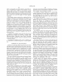
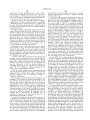
An anti-eye strain apparatus and method Which automati
cally adjusts the brightness of a display to cause the muscles
of the eyes of the user to adjust and refocus such that eye
fatigue or tiredness is reduced or eliminated. The brightness
is varied Within a particular range and the brightness Within
this range is occasionally or periodically adjusted. The
changing brightness preferably folloWs a predetermined
pattern or cycle. These brightness changes may be percep
.. 345/11
tible or imperceptible to the vieWer. The brightness of the
5/1996 Dillon, III ................................. .. 345/6
display may be adjusted electronically or mechanically, for
12/1995
McManus et a1. ..... ..
OTHER PUBLICATIONS
Diamond Multimedia Systems, Inc., “Adjust Your Display’s
example by a potentiometer, by a computer attached to a
monitor, for example by an application or softWare, or by
changing the palette of colors or the gray scale.
Brightness” (1994).
89 Claims, 11 Drawing Sheets
PC World, pp. 107—108 (Apr. 1995).
IE UIIIIBU
mgdgmcm 7| ..............................................................
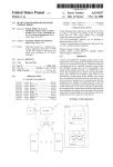
Selected \
Rondorn
Pattern Selection
Brightness
U.S. Patent
Aug.3, 1999
Sheet 1 0f 11
5,933,130
//0
[/2
BACKLIGHT
CONTROL
SOFTWARE
FL!
[/5
CENTRAL
<--> PROCESSING <___> BADCR'<“L/'EGRHT
UNIT
Ham‘ —-»
09.1
U S. Patent
Aug. 3, 1999
5,933,130
Sheet 2 0f 11
/'_Z4
|_
~
_
_
_
_
_
_
_
_
_
_
_l
_
_
_
_
_
_
_
_
_
_
_
_
_
__
I
|
|
RANDOM NUMBER
|
|
|
22
:
GENERATOR
:
I
,
CLOCK
30
CENTRAL
BRIGHTNESS
—~ PROCESSING <——>
CONTROL
UNIT
SOFTWARE
L _______________________ __ _ 3
/ 32
DIGITAL-TO-ANALOG
CONVERTER(S)
F
BRIGHTNESS
CONTROL
34
/'35
_—’ D'SPLAY
U.S. Patent
Aug.3, 1999
Sheet 3 0f 11
5,933,130
RANDOM NUMBER
GENERATOR
CLOCK
CENTRAL
BRIGHTNESS
———> PROCESSING <——>
CONTROL
UNIT
SOFTWARE
ELECTRONICALLY
CONTROLLED
POTENTIOMETER(S)
I f”
BRIGHTNESS
CONTROL
K52
—'—-—> DISPLAY
U.S. Patent
09.4
09.5
Aug.3, 1999
Sheet 4 0f 11
5,933,130
U.S. Patent
:mE:
.
Aug.3, 1999
Sheet 5 0f 11
Eoncm 5co0z3mwa
\/832m
5,933,130
U.S. Patent
Aug.3, 1999
Sheet 7 0f 11
5,933,130
/60
SELECT FIXED
RANGE OF
BRIGHTNESS
SELECT
FIXED
PERIOD
RANDOM
[67
SELECT
FIXED
PATTERN
RANDOM
014.9
U.S. Patent
Aug.3, 1999
Sheet 8 0f 11
{70
LOAD
SELECTED 0R DEFAULT
RANGE
l K72
LOAD
SELECTED OR DEFAULT
PERIOD
l
f"
LOAD
SELECTED OR DEFAULT
PATTERN
T
f”
VARY DISPLAY BRIGHTNESS
IN ACCORDANCE WITH
SELETED OR DEFAULT
RANGE, PERIOD AND PATTERN
STOP
SIGNAL
?
5,933,130
U.S. Patent
Aug.3, 1999
MANUAL
POTENTIOMETER
5/
/
52
Sheet 9 0f 11
/
—9\c
oE
\
°
5,933,130
M
BRIGHTNESS
CONTROL
AUTOMATIC
POTENTIOMETER
85
DISPLAY
U.S. Patent
Aug. 3, 1999
5,933,130
Sheet 10 0f 11
/
90
DATA
STORAGE
MEDIA
K95
COLOR
CONTROL
SOFTWARE
K92
CENTRAL
PROCESSING
UNIT
[.94
PALETTE
OF COLORS
CONTROLLER
DISPLAY
/7_'g. l2
U.S. Patent
Aug. 3, 1999
5,933,130
Sheet 11 0f 11
/
I00
DATA
STOR
MED
K- I00’
GRAY SC
CONTR
SOFTWARE
I02
v
/
CENTRAL
<—_> PROCESSING
UNIT
/
I04
GRAY
SCALE
CONTROLLER
K
DISPLAY
I06'
5,933,130
1
2
ANTI-EYE STRAIN APPARATUS AND
METHOD
emits. For example, if every red, green and blue dot in a
particular pixel is struck by equally intense electron beams,
the result is a White dot. As is Well knoWn, different colors,
shades and brightness are obtained by varying the intensity
of the electron beams striking that pixel.
FIELD OF THE INVENTION
The present invention relates in general to display screens
and, in particular, to an anti-eye strain apparatus and method
After the electron beam leaves a particular phosphor, the
phosphor continues to gloW brie?y, a condition called per
sistence. For an image to remain stable, the phosphor must
be reactivated by repeated scans of the electron beam. When
the fading of the phosphor betWeen repeated scans of the
for a display screen.
BACKGROUND OF THE INVENTION
People use display screens for a Wide variety of purposes.
screen becomes noticeable, the screen ?ickers. This ?icker
For example, display screens may be used to display speci?c
information from devices such as oscilloscopes, radars,
televisions, projection systems, and other types of electronic
is ordinarily considered undesirable. Accordingly, the moni
tor must continually re-energiZe the various phosphors in the
instruments. The information may be shoWn on many types
15
of display screens such as cathode ray tubes (“CR ”), liquid
With a high refresh rate, the screen is more frequently
redraWn and the eye of the vieWer tends to see a smooth,
crystal displays (“LCD”), and gas plasma displays.
non?ickering display. A typical cathode ray tube has a
Display screens are also frequently used in conjunction
With computers. Computers are used for many purposes,
refresh rate of betWeen about 60 and 70 cycles per second.
Early cathode ray tube display screens could only turn a
particular pixel in the display on or off. This made it difficult
to achieve subtle distinctions in colors because an energiZed
including personal, educational, and Work uses. People often
vieW these display screens for extended periods of time.
Extended vieWing of the screen can cause eye strain and eye
fatigue, leading to physical and mental discomfort for the
vieWer. This problem is becoming increasingly prevalent as
more jobs and businesses require employees vieW display
display to eliminate ?icker. This continual redraWing or
re-energiZing of the display is the monitor’s refresh rate.
pixel displayed only a single color at the same brightness. In
contrast, current display screens often utiliZe a variable
25
screens for extended periods of time.
graphics-array (“VGA”) display adaptor Which alloWs the
Cathode ray tubes are a very common type of display
screen used With computers. Cathode ray tubes are also used
strength of the different electron beams to vary so that the
color and brightness of each pixel can be varied. This alloWs
the monitor to display a Wide range of colors because the
in a Wide range of other applications including television
brightness and color of each pixel is individually controlled.
picture tubes, video monitors, and oscilloscopes. As is Well
In further detail, a typical cathode ray tube display used
knoWn, a cathode ray tube includes an electron gun Which
emits a stream of electrons. A ?rst anode focuses the
electrons into a narroW beam and accelerates the electrons to
With a computer system receives signals from sources such
as the operating environment or application softWare, and
these signals are sent to the input/output hardWare of the
a greater speed. A second anode gives the electrons still
more speed. De?ection coils or plates surrounding a portion
35
of a cathode ray tube control the location at Which the
electron beams strike the inner surface of the display screen.
The inner surface of the display screen is typically coated
With a phosphor material Which gloWs When struck by an
electron to create an individual point of light.
A typical cathode ray tube display screen includes thou
sands of these individual points of light Which create the
desired image on the display screen. As is Well knoWn, a
pixel or picture element is a small logical unit that is used to
build an image on the display screen. A single pixel is
computer, Which frequently contains the VGA display adap
tor (the VGA display adaptor is often built into the moth
erboard of a personal computer). The VGA display adaptor
processes the signals through a circuit called a digital-to
analog converter (“DAC”). Frequently, the digital-to-analog
converter is contained Within a specialiZed chip. Often this
specialiZed chip contains three digital-to-analog converters
in order to control the three colors used in the display.
As is knoWn in the art, the digital-to-analog converter
compares the values sent by the computer to a table that
usually created by several adjoining points of light. The
contains the matching voltage levels for the three colors
needed to create the particular color and brightness. A
precise amount of voltage from each electron gun then
feWer the dots of light used to create a pixel, the higher the
resolution of the display screen.
brightness.
45
energiZes each pixel to reproduce the desired color and
display. The color monitors that Were originally used With
devices such as computers had relatively crude color and
As the number of colors increases and the resolution of
the display screens improve, a more realistic display is
created, Which alloWs more information to be conveyed to
graphics, and many could display only four basic colors.
Current monitors, hoWever, commonly have a palette of 256
of users of display screens, and the amount of time Which
It is knoWn to utiliZe cathode ray tubes to create a color
colors. In fact, many color monitors noW have the capacity
to display thousands of colors. Modern monitors also often
include a larger number of pixels than the older monitors,
and this alloWs the desired image to be more accurately
the vieWer. This improved display has increased the number
55
people vieW display screens.
Typically electronic display screens alloW the brightness
or intensity of the screen to be adjusted for different lighting
conditions. A knoWn method to adjust the brightness of a
represented on the screen.
display screen is to use a variable resistor or potentiometer.
A typical cathode ray tube color monitor contains three
electron guns, one gun for each color of red, green and blue.
The potentiometer alloWs the intensity of the electron beams
to be controlled, and this alloWs the brightness of the display
The electron guns send out a stream of electrons Which strike
screen to be adjusted. Conventionally, a protruding knob or
other rotatable member, often labeled as a brightness control
knob, is connected to the potentiometer such that the user
the phosphors of a particular color coating the inside surface
of the screen. In general, the amount of light that a particular
phosphor emits is dependent upon the strength of the elec
tron beam Which strikes a given phosphor because the
stronger the electron beam, the more light the phosphor
65
can manually adjust the brightness of the screen.
It is also Well knoWn to use a liquid crystal display
(“LCD”) screen for a Wide variety of purposes. For example,
5,933,130
3
4
LCDs are frequently used With computers, especially por
of the page momentarily changes the brightness of the page.
Therefore, as the eye muscles adapt to this change, tiredness
table or notebook-type computers. As is known to one of
ordinary skill in the art, LCDs are electronically sWitched
display panels that make use of changes in the re?ective
properties of liquid crystals in series With an electronic ?eld.
and eye fatigue may be delayed or avoided.
In contrast, a computer display has no corresponding
change in brightness and a user often has a tendency not to
look around the room or at other objects of different bright
LCDs often include a backlight or other lighting source such
that a person can read the display in various lighting
conditions.
Some display screens connected to a computer alloW the
brightness of the screen to be adjusted by the computer. For
ness. Accordingly, there is a need for a computer user to
occasionally adjust or refocus his or her eyes in order to
avoid eye strain and fatigue.
10
example, the Macintosh PoWerbook sold by Apple
The Applicant believes that a reduction in eye strain and
fatigue Will occur if the muscles of the eyes are regularly
Computer, Inc. alloWs the user to adjust the backlight of the
moved and adjusted. For example, the Applicant has
LCD screen. The backlight of the screen is typically con
trolled by entering one or more commands through the
constant outstretched position for a limited period of time,
keyboard or mouse of the computer. Alternatively, the
observed that a person can only hold his or her arm in a
15
backlight may be controlled by the computer executing an
application or third-party softWare program. For example,
the backlight brightness for the PoWerbook computer may
be adjusted by softWare Which controls the backlight driver.
As Well knoWn to one of ordinary skill in the art, the
backlight driver is a standard MacIntosh driver that can be
controlled by a series of commands or calls, and these calls
may be used to set or change the backlight of the screen to
the desired level.
In addition, some display screens may alloW the color to
be adjusted by a computer. For example, a company called
MAG Innovision of Santa Ana, Calif., sells a product called
but a person regularly moving his or her arm—such as an
orchestra conductor—can hold their arm outstretched for a
much longer period of time. Similarly, the Applicant
believes that the regular adjusting and exercising of the eye
muscles Will alloW the person to vieW an electronic display
screen for a much longer period of time than Would other
Wise be possible.
The Applicant believes the moving and adjusting of the
25
muscles in the person’s eyes should occur regularly to
prevent the muscles of the eye from being held in a constant
state of tension. HoWever, Applicant believes that very
active movement of the muscles of the eye should also be
avoided to prevent fatigue. Accordingly, the brightness of
Advanced Display Calibration Which alloWs commands
the display is preferably adjusted so that the muscles of the
entered through a keyboard or mouse to control the color of
a computer monitor.
eye are regularly exercised, but not to the extent that the eye
muscles are fatigued.
The present invention is an anti-eye strain apparatus and
method Which overcomes the above-described disadvan
Accordingly, the brightness and/or color of a display may
be controlled by a system having these or similar capabili
ties.
SUMMARY OF THE INVENTION
tages. The apparatus and method includes varying the
35
inventive concept is applicable to brightness, contrast, and
As the use of electronic display screens has become more
backlight, as Well as gray scale and color levels.
In accordance With one aspect of the invention, the
brightness of a display screen varies to cause the muscles of
Widespread, certain problems have also become more com
mon. For instance, electronic display screens are noW being
utiliZed more frequently and for extended periods of time.
the eye of the vieWer to adjust. Preferably, the display is set
to a generally acceptable level of brightness and the bright
Because the display screens are maintained at a roughly
constant distance of approximately 20 inches (50 cm) from
ness then occasionally or periodically varies Within a range
the vieWer’s eyes, the same eye muscles are in constant
tension to focus on the screen. It is believed that this causes
signi?cant amounts of stress and fatigue in the eye muscles.
brightness of the display screen to decrease eye strain of a
person vieWing the screen. It Will be understood that the
45
about this selected general level of brightness. The changing
brightness of the display preferably folloWs a selected
This problem is often aggravated by the frequent, almost
pattern or cycle such that the muscles of the eyes of the
daily use of display screens.
The stress associated With vieWing an electronic display
vieWer must occasionally adjust, avoiding eye tiredness and
screen may result in headaches or other maladies. It is
perceptible or imperceptible to the vieWer.
Another aspect of the present invention is utiliZing a
computer to control the brightness of the computer screen
automatically. The settings such as the range of brightness,
fatigue. These brightness changes may be substantially
believed that these problems are sometimes caused, at least
in part, by the eye continuously focusing on a display screen
of generally constant brightness. It is believed that because
the muscles of the eye are often held in the same state for an
the time for each brightness adjustment cycle, and the
extended period of time, extreme discomfort to the user may
result because the muscles in the eye are not permitted to
adjust, refocus or relax.
This problem is particularly acute With computer screens
pattern folloWed in adjusting the brightness may be con
trolled by the user through commands entered by a keyboard
55
or mouse. The automatic control of brightness may be
implemented using application or utility softWare.
and other electronic displays that are speci?cally con?gured
Yet another aspect of the present invention is an automatic
screen brightness controller having brightness control soft
to have a generally constant intensity or brightness. Thus,
the vieWer stares at a screen from a generally constant
Ware stored in a machine readable storage media and a
distance and same brightness for an extended time period.
Accordingly, the muscles of the eye are not given the
opportunity or ability to relax or adapt to changing stimulus.
processor is operatively connected to the storage media. The
screen brightness controller is connected to a display of the
type that permits the brightness to be varied and the softWare
includes instructions that direct the brightness of the display
The Applicant believes, for example, that less eye strain
occurs in reading a book than in vieWing a computer screen
because each time the reader turns the page, the reader must
refocus his or her eyes upon the next page and the turning
65
to be varied over time in accordance With a pattern. A still
further aspect of the present invention is to control the
palette of colors or gray scale such that the shade of color
5,933,130
5
6
(including gray, for example) is occasionally or periodically
and that such backlight control drivers are found, for
eXample, in certain laptop computers, such as the Macintosh
changed in order to reduce or eliminate eye strain of the
vieWer.
PoWerbook by Apple Computer, Inc.
In greater detail, in a manner knoWn to one of ordinary
BRIEF DESCRIPTION OF THE DRAWINGS
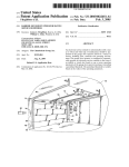
skill in the art, the central processing unit 14 preferably
eXecutes a series of steps set forth in the softWare 12 to
These other features of the invention Will noW be
control the backlight driver 16. More preferably, the central
described With reference to the draWings of preferred
processing unit 14 eXecutes one or more calls to the back
embodiments, Which are intended to illustrate and not to
limit the invention, in Which:
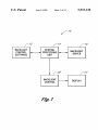
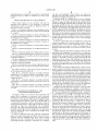
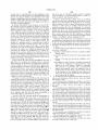
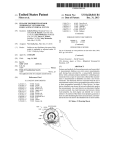
FIG. 1 is a schematic diagram of an embodiment of the
10
light driver 16, and the central processing unit 14 then sends
signals to the backlight control 20. These signals are used to
set the brightness of the backlight in accordance With the
invention, providing for automatic variation of the backlight
instructions set forth in the softWare 12. One of ordinary
of a display;
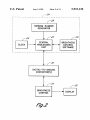
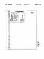
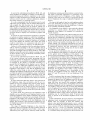
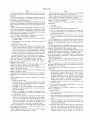
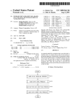
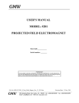
FIG. 2 is a schematic diagram of another embodiment of
skill in the art Will readily recogniZe that the backlight driver
the present invention, providing for automatic variation of
the brightness of a display;
and backlight controls are Well knoWn in the art. Further, for
15
driver softWare.
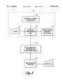
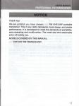
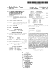
FIG. 3 is a schematic diagram of a further embodiment of
It Will be appreciated that the Applicant is using the
the present invention, providing for automatic variation of
the brightness of a display;
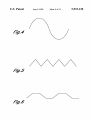
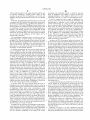
FIG. 4 is a schematic diagram of a representative pattern
central processing unit in general terms, and that one of
ordinary skill in the art Will understand that a central
processing unit can include a variety of combinations of
or cycle;
FIG. 5 is a schematic diagram of an additional pattern or
hardWare and softWare that can be used to execute a series
of steps.
cycle;
FIG. 6 is a schematic diagram of a further pattern or cycle;
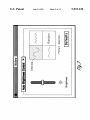
FIG. 7 is a diagram illustrating the graphical user interface
of an embodiment of the invention, set up for electronically
25
cessing unit 22. The central processing unit 22 is preferably
brightness control softWare 30. Although not shoWn, the
FIG. 8 is a diagram illustrating the graphical user interface
of another embodiment of the invention, set up for elec
computer 24 preferably has an electronic storage media such
tronically controlled backlight;
as random access memory or a hard disk. The brightness
control softWare 30 is preferably stored in the memory of the
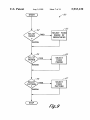
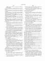
FIG. 9 is a ?oWchart for the softWare implementation of
computer 24.
a program used by the central processing unit shoWn in FIG.
3;
35
in the brightness control softWare 30. The central processing
converter 32 converts a digital signal (a digital number) to
an analog signal (a voltage level). It Will be understood that
more than one digital-to-analog converter 32 may be used to
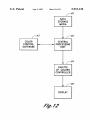
FIG. 12 is a schematic diagram of another preferred
embodiment of the present invention, Wherein the colors are
convert the signal from the central processing unit 22 into an
varied; and
45
DETAILED DESCRIPTION OF THE
PREFERRED EMBODIMENTS
electronic storage media such as a hard disk and an appro
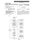
the anti-eye strain apparatus 10 includes backlight control
55
central processing unit (or “CPU”) 14 eXecutes the series of
commands or steps and communicates With a backlight
driver 16. The central processing unit 14 sends signals to a
backlight control 20 so that the brightness of an associated
screen or display 21 can be controlled. The display 21 is
preferably an LCD.
priate amount of random access memory. The central pro
cessing unit 40 eXecutes a series of commands or steps in
accordance With the instructions set forth in the control
softWare 41 and sends a signal to an electrically controlled
potentiometer or variable resistor 48. It Will be understood
that one or more potentiometers 48 may be used to vary or
It Will be understood that this preferred embodiment
alloWs the central processing unit 14 to control and com
municate With the backlight driver 16. It Will be readily
appreciated by one of ordinary skill in the art that a central
processing unit 14 is typically a component of a computer
analog signal. The analog signal is then transmitted to a
brightness control 34 Which is used to control the brightness
of a display 36. The display 36 is preferably a CRT.
Another preferred embodiment is shoWn in FIG. 3. In this
embodiment, the brightness of a display is controlled by a
central processing unit 40 and brightness control softWare
41. The central processing unit 40 is preferably a component
of a computer 42. The computer 42 preferably includes a
random number generator 44, a clock 46, and the usual
As shoWn in FIG. 1, an anti-eye strain apparatus and
method 10 is con?gured in accordance With a preferred
embodiment of the present invention. In this embodiment,
softWare 12 stored in memory (such as on the hard disk of
a computer) that speci?es a series of commands or steps. A
The central processing unit 22 eXecutes a series of com
mands or steps in accordance With the instructions set forth
unit 22 is also in communication With a digital-to-analog
converter 32. As Well knoWn in the art, the digital-to-analog
connected thereto;
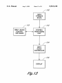
FIG. 13 is a schematic diagram of another preferred
embodiment of the present invention, Wherein the gray scale
is varied.
Another preferred embodiment is shoWn in FIG. 2. In this
embodiment the brightness is controlled by a central pro
located Within a computer 24. The computer 24 preferably
includes a clock 26, a random number generator 28, and
controlled brightness;
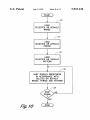
FIG. 10 is a ?oWchart of the operation of the embodiment
of the invention shoWn in FIG. 9;
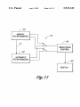
FIG. 11 is a schematic diagram of another preferred
embodiment of the present invention, providing for auto
matic variation of brightness of any computer that may be
eXample, the automatic backlight control softWare could be
readily combined With and made a part of the backlight
65
control the signal from the central processing unit 40. The
potentiometers 48 may be connected in series or in parallel
to control the signal from the central processing unit 40.
Additionally, as discussed in greater detail With respect to
FIG. 11 beloW, the potentiometers 48 may be manually or
automatically controlled. The potentiometer 48 then sends a
signal to a brightness control 50 such that the brightness of
a display 52 can be adjusted. The display 52 is preferably a
CRT.
5,933,130
7
8
In each of the embodiments described in FIGS. 1, 2, and
3, the brightness or backlight of a display is controlled by a
central processing unit Which is responsive to the control
softWare. It Will be understood, for example, that this control
softWare could be part of a softWare application, indepen
the brightness remains generally proximate a selected value.
example, if the range is 10 percent of a 50 percent general
level of brightness, the range of adjustable brightness is 5
dent utility softWare, or operating system.
percent.
It is also contemplated that this invention may be used
With many types of displays. One of ordinary skill in the art
Will recognize that this invention may be used With may
different types of displays such as monitors, cathode ray
The time is the length of time for each brightness adjust
ment cycle. Preferably, the system is con?gured to alloW for
The range is preferably expressed as a percentage of the
selected general level of brightness of the display. For
successive time intervals to alloW the brightness of a display
10
tubes, display screens, liquid crystal displays, radar screens,
oscilloscopes, gas plasma displays and the like. It Will also
be understood that the display may consist of a Wide variety
of knoWn means to display text, information, graphics and
the like.
It Will also be appreciated that this application is intended
according to a speci?c pattern. The pattern alloWs the
brightness of the display to be adjusted in a controlled or
15
to include any knoWn method to control the backlight or
brightness of a display. Additionally, it is contemplated that
in addition or instead of varying the brightness or backlight
level of the display, the contrast, color, and/or gray scale
25
used With a backlight control as shoWn in FIG. 1, and a CRT
It Will be appreciated that each of these settings may be set
by the user. Alternatively, the softWare and central process
ing unit may be con?gured to establish each of the settings.
Preferably, the user may establish some of the settings While
those factors not chosen by the user are determined by the
default settings. The folloWing embodiments set forth in
greater detail preferred embodiments of the invention. It Will
be understood, hoWever, that any combination of these
settings and value for these settings may be used to adjust
the brightness of the display.
In one preferred embodiment, the user sets the general
level of brightness of the display. For example, the user may
set the general level of brightness of the display to 50
percent of the total brightness of the display. The range is set
display is preferably used With a digital-to-analog converter
as shoWn in FIG. 2 or an electronically controlled potenti
ometer as shoWn in FIG. 3.
In each of the embodiments described in FIGS. 1, 2, and
3, the control softWare and central processing unit are
con?gured to alloW the brightness or backlight of a display
to be controlled. In a preferred embodiment, the brightness
or backlight of the display is controlled according to a
general level of brightness of the display is set at a desired
level, a range in Which the brightness Will vary is then
set—the range is preferably relative to the general level of
brightness of the display, a time that the brightness varies
Within the selected range is also set, and the pattern for
speci?c sequence.
control softWare and central processing unit or are set to
could be varied alone or in conjunction With one or more
other features to reduce eye strain for an individual user.
Further, it Will be understood that the embodiment chosen
Will be selected according to the type of display that is
desired to be controlled. For example, an LCD is preferably
to be cyclically periodically adjusted.
The brightness of the display is also preferably adjusted
to a predetermined or default value, such as, for example,
about 10 percent of the general level of brightness selected
by the vieWer. Thus, the softWare and the central processing
unit are advantageously con?gured to vary the brightness of
35
the display Within a range of about 10 percent of the
user-selected 50 percent general brightness level. Therefore,
the brightness of the display increases and decreases a
maximum of 5 percent from the general brightness level.
Preferably, the brightness varies Within a range centered
about the general brightness level. Accordingly, in this
adjusting the brightness Within the speci?c time and range is
set. Thus, the general level of brightness, range of adjustable
example, the brightness Would vary Within the range of
about 47.5 and 52.5 percent of the total brightness of the
brightness, time for each brightness adjustment cycle, and
display.
pattern for varying the brightness are set and this informa
tion is used to vary the brightness of the display in a speci?c
45
It Will be understood that the range of brightness does not
have to be centered about the general level of brightness. For
manner.
example, the general level of brightness could be the maxi
It Will be understood that these factors—the general level
of brightness, range, time and pattern—may be set in a
mum brightness and the brightness Would vary Within a
range that does not exceed this maximum brightness.
number of Ways. For example, they may be preset, depen
dent upon ambient lighting conditions, selected by the
Alternatively, the general level of brightness may be the
minimum brightness and the brightness Will automatically
central processing unit or selected by the user. Preferably,
these factors are set such that the brightness of the display
vary Within a range that does not go beloW this minimum
level of brightness. For example, the general brightness level
exercises the muscle in the eye of the user to prevent or delay
eye strain or fatigue.
may be set by the user at 70 percent of the maximum
maximum brightness of the display. Preferably, the general
brightness level of the display, and the softWare may vary
the brightness Within a range of about 10 percent. Thus, the
brightness may be varied betWeen about 70 percent and
about 77 percent of the maximum brightness level of the
level of brightness is expressed as a percentage of the total
display.
In greater detail, the general level of brightness of the
55
display is set to a selected level of brightness relative to the
brightness of the display. For example, the general level of
brightness may be 50 percent of the total brightness of the
display. The invention is also preferably con?gured to vary
the brightness proximate the selected general level of bright
In this embodiment, the time period for each brightness
ness of the display.
The range of adjustable brightness is the extent the
brightness varies. For example, the range could be relatively
large such that the brightness varies Within a Wide range.
Alternatively, the range could be relatively small such that
65
adjustment cycle is preferably predetermined or set to a
default value, for example, of about ?ve minutes. The
pattern is also preferably predetermined or set to a default
pattern. For example, the pattern preferably choose is a sine
Wave as shoWn in FIG. 4. Alternatively, the predetermined
pattern may be a series of continually increasing and
decreasing ramps or a saW-tooth pattern as shoWn in FIG. 5,
or a combined ramp and step pattern as shoWn in FIG. 6. It
5,933,130
9
10
Will be understood that a Wide range of known patterns may
processing unit preferably selects a relatively narroWer
range of brightness, for example 5 percent, because the
changing brightness of the display is believed to be more
be selected, including a random pattern. Thus, in this
example, the general level of brightness is set by the user
While the range, period and pattern are preset or set to default
values.
noticeable to the user at a loWer overall brightness level.
It Will be understood that a range of brightness of 5
percent, or even less, may be selected and the display Will
Preferably, this embodiment described above is used With
a computer and CRT display. More preferably, this embodi
automatically be adjusted to vary Within this relatively
ment uses a computer having a graphical user interface, as
narroW selected range, or a range of more than 10 percent
shoWn in FIG. 7. The Auto Brightness Control feature seen
in the graphical user interface is preferably selected by a user
by a keyboard or mouse. The user then sets the brightness of
larger range. It Will be appreciated that a relatively large
range may result in automatic changes to the brightness that
may be selected such that the brightness Will vary over a
display to the desired general level of brightness. In this
example, the general brightness level has been set to about
50 percent. As set forth above, the range, period and pattern
are set such that the brightness of the display can be
are generally perceptible to the vieWer. Alternatively, a
generally narroW range can be selected such that the changes
in the brightness are substantially imperceptible to the
15
automatically controlled.
The embodiment described above can also be used in
While providing eye-strain relief.
conjunction With a computer having an LCD display. For
example, FIG. 8 shoWs a graphical user interface in Which
the Auto Backlight command has been selected by the user.
The user then sets the backlight to the desired general level,
such as 50 percent. The range, period and pattern are
preferably set as set forth above such that the brightness of
the display is automatically adjusted.
In another embodiment, the user sets the desired general
vieWer. The narroW range of 10 percent or less is preferred
because When combined With a relatively sloW rate of
change, the variations are imperceptible to the ordinary user
As shoWn in FIG. 9, the period 64 is also selected. The
period may be a ?xed time interval Which is preset or set by
the user. For example, a ?xed period of about ?ve minutes,
or even longer, may be selected. A default interval of ?ve
minutes is preferably selected. It Will be appreciated that the
brightness of the display may be adjusted at intervals of less
25
than ?ve minutes such that the eyes of the vieWer must more
level of brightness While the central processing unit and
control softWare determine the range, period and pattern. As
frequently adjust to the brightness of the display. The
brightness of the display may also be adjusted at intervals of
seen in FIG. 9, the central processing unit of the embodiment
shoWn in FIGS. 1, 2 and 3 preferably folloWs a ?oWchart 60
every second or even less such that the brightness is rapidly
to adjust the brightness of the display. For example, the
or almost constantly changing. Alternatively, the period may
be randomly chosen using signals from a random number
range of brightness 62 selected may be a ?xed range or a
generator in a manner similar to that described above.
random range. A?xed range of brightness, for example, may
The selected period preferably applies to one brightness
adjustment cycle and determines hoW long it takes that cycle
be preset before delivery to the user or selected by the user.
Alternatively, the range of brightness may be randomly
varied. In order to randomly select the range, the central
35
at the sine Wave is the midpoint of the increasing section.
One cycle in the case of the ramp Wave shoWn in FIG. 5 is
one ramp up and one ramp doWn. Preferably, the starting
processing unit preferably receives signals from a random
number generator seen, for instance, in FIGS. 2 and 3. For
example, if the random number generator supplies numbers
betWeen 1 and 256, the system is preferably con?gured to
select a range of brightness of 5 percent for numbers
betWeen 1 and 100; a range of brightness of 10 percent is
selected if the number is betWeen 101 and 200; and a range
of brightness of 15 percent is selected if the number is
betWeen 201 and 256. Accordingly, in this example, if a
number betWeen 101 and 200 is generated by the random
number generator, then the range of brightness is 10 percent
of the user selected general level of brightness.
to run. One cycle in the case of the sine Wave is shoWn in
FIG. 4. Preferably, the starting and ending point for the cycle
point is the midpoint of the increasing section, and the
ending point is the midpoint of the next increasing section.
One cycle in the case of the combined ramp and step Wave
shoWn in FIG. 6 is one ramp up to the ?at section, the upper
?at section, one ramp doWn, and the loWer ?at section.
45
Preferably, the starting point is the midpoint of the increas
ing section, and the ending point is the midpoint of the next
increasing section.
In each of the embodiments of FIGS. 4, 5, and 6, the Wave
Will be applied at the appropriate starting point for each
cycle to cause the appropriate change in brightness. For
example, the sine Wave Will preferably be applied around the
In greater detail, the range through Which the level of
brightness can be varied, Whether ?xed or random, can be set
anyWhere betWeen Zero and 100 percent of the general level
of brightness. While under some circumstances, large
brightness level ranges may be appropriate, they can result
selected brightness level so that half of the maximum change
in brightness is higher and half is loWer than the selected
general level of brightness. In particular, as shoWn in FIG.
in some problems. For example, if you have a brightness
range of 80 to 100 percent, some text or graphics may not 55 4, the brightness increases during the ?rst portion of the
be easily read during the loWer part of the range. Thus, a
range of brightness betWeen about 2 and about 30 percent is
cycle. The brightness Will then decrease from the point of
greatest brightness to the point of loWest brightness. The
preferably selected and more preferably a range betWeen
about 5 and about 15 percent is selected. Most preferably, a
range of brightness of about 10 percent is selected. A range
of brightness of about 10 percent is preferably used as a
default setting if no range is selected.
brightness then returns to the selected brightness level.
Preferably, the system is con?gured to alloW for succes
sive brightness adjustment cycles. More preferably, the
system continues to adjust the brightness according to the
selected general level of brightness, range, period and pat
tern until the user resets one or more of the factors or the user
In addition, if the general level of brightness of the display
is proximate the maximum brightness of the display, then a
range of brightness of, for example, 10 percent, is preferable
selected. HoWever, if the general level of brightness is set
near the minimum brightness of the display, the central
stops the system.
65
Although not shoWn, it is also understood that time
intervals of no adjustment, Where the selected range 62 and
selected period 64 remain in their default settings, could be
5,933,130
11
12
incorporated between adjustment cycles. These “silent”
period for the cycle is ?ve minutes, one minute for each of
the ramp sections of the cycle and 1 1/2 minutes for the ?at
times could be randomly interspersed and could be of
random lengths. It Will be understood that these silent times
can also be at times and lengths selected by either the user
or the control softWare and control processing unit.
As shoWn in FIG. 9, the pattern 68 Which the brightness
is adjusted may be ?xed or randomly selected. For example,
portions of the cycle.
In operation of this preferred embodiment, the user sets
the general level of brightness of the display to about 50
percent of the total range of adjustable brightness. The user
also sets the range of brightness to a random setting; a
?ve-minute length of time for the brightness adjustment
a ?xed pattern may be chosen by the user or a pattern may
cycle; and a pattern having a ramp With a ?at top as shoWn
in FIG. 9. In this case the random number generator is used
by using a random number generator in a manner similar to
to select the range of brightness. For example, if the random
that described above.
number generator supplies numbers betWeen 1 and 256, the
The selected pattern is preferably varied in any of a Wide
system is advantageously con?gured to select a range of
range of knoWn patterns, such as for example the sine Wave
brightness of 5 percent for numbers betWeen 1 and 100; a
as shoWn in FIG. 4, the saW-tooth pattern as shoWn in FIG.
range of brightness of 7 percent is selected if the number is
5, or the combined ramp and step pattern as shoWn in FIG. 15
betWeen 101 and 200; and a range of brightness of 10
6. It Will be understood that a Wide variety of knoWn patterns
be preset. Alternatively, the pattern may be randomly chosen
percent is selected if the number is betWeen 201 and 256.
Accordingly, in this embodiment, if a number betWeen 201
may be utiliZed to vary the rate of change of the brightness.
Preferably, the pattern is selected such that the eye muscles
and 256 is generated by the random number generator, then
the range of brightness is 10 percent of the general level of
of the user are adjusted an optimum amount With a minimum
amount of distraction to the vieWer. The Applicant believes
brightness. Thus, in this example, the brightness ranges
this Will reduce or eliminate eye strain and alloW a user to
betWeen about 47.5 percent and about 52.5 percent of the
vieW the display for extended time periods.
Accordingly, in this example the general level of bright
ness is knoWn, the range over Which the brightness varies is
knoWn, the time length of each cycle is knoWn, and the
general level of brightness, and the system is con?gured to
adjust the brightness Within the ?ve minute period according
25
pattern in Which the brightness varies is knoWn. The com
puter is con?gured to use this information to calculate the
to the ramp and step pattern shoWn in FIG. 6. Prior to the end
of the period, a neW random number is generated to select
a neW range of brightness for the subsequent period. This
alloWs the system to continuously vary the brightness in the
desired brightness for the display and the desired change in
the brightness of the display.
As shoWn in FIG. 10, the operation of the computer, for
example, involves loading the selected or default range 70,
above-described manner until the user stops the system or
the user changes one or more of the factors.
As seen in FIG. 11, in another preferred embodiment, in
a system so equipped, a manual potentiometer 80 is used in
the selected or default period 72, and the selected or default
pattern 74. Loading of information into a computer is Well
knoWn to one of ordinary skill in the art. The computer then
uses this information to vary the display brightness in
accordance With the selected or default range, period, and
conjunction With an automatic potentiometer 82. The
manual potentiometer 80 and the automatic potentiometer
82 may be connected by a sWitch 84 as shoWn in FIG. 11,
or the manual and automatic potentiometers may be con
nected in series or in parallel according to the desired
pattern 76. The brightness is adjusted according to the
arrangement of the potentiometers. The manual potentiom
factors until a stop signal 78 is received.
It Will be readily understood and appreciated that the
eter 80 is preferably a conventional brightness control for a
range of adjustable brightness, the length of each brightness
potentiometer 80 or the automatic potentiometer 82 to send
a signal to a brightness control 86. The brightness control 86
is used to control the brightness of a display 88. It Will be
display. A sWitch 84 preferably alloWs either the manual
adjustment cycle and the pattern used to determine the
changing brightness may be individually changed or
changed in combination.
These factors may be adjusted such that the changes to the
brightness of the display are generally perceptible to the
understood that this manual potentiometer 80, for example,
45
user. This Will cause the muscles in the eye of the user to
adjust to these changes. More preferably, these factors are
may be manually set by the user and adjusted according to
the ambient lighting conditions. It Will also be understood
that a potentiometer is intended to include variable resistors,
arranged such that the brightness changes are substantially
solid-state devices, or the like Which may be used to vary the
resistance or voltage that appear across the device.
imperceptible to the user. Thus, the user is adjusting the
muscles in his or her eyes Without being aWare of the
The automatically controlled potentiometer 82 is prefer
ably con?gured to Work in conjunction With the manual
changing brightness of the display. For instance, the bright
potentiometer 80 such that the user can readily change the
ness of the display may be substantially imperceptibly
changed by gradually changing the brightness over an
extended time or, alternatively, the brightness may be
brightness of a display by adjusting the manual potentiom
eter 80 to the desired general level of brightness. The
55
changed very rapidly but in increments or steps that are
substantially imperceptible to the user.
In a preferred embodiment, the user sets the general level
over a line 81. Then When it is desired to automatically vary
the brightness, the automatic potentiometer 82 is sWitched in
using sWitch 84. The automatic potentiometer 82 preferably
includes the elements shoWn in FIG. 3, meaning the central
processing units 40, the brightness control softWare 41, the
random number generator 44, and the electronically con
trolled potentiometer 48. Note that an automatic potentiom
of brightness for the display and the range of brightness in
Which the display Will automatically vary is selected by the
user or preset before shipping. This range is preferably
betWeen about 2 and 30 percent, more preferably betWeen
about 5 and about 15 percent and most preferably the range
is about 10 percent of the total brightness range. The user
then inputs the desired time of the brightness adjustment
automatically controlled potentiometer 82 monitors the
brightness level that is set by the manual potentiometer 80
eter of this type could be incorporated into a monitor
cycle and the user then selects the pattern, Which is prefer
independent of any computer connected to the monitor by
providing all these elements, including a special purpose
ably a ramp With a ?at top as shoWn in FIG. 6. The preferred
processor in the monitor itself. The automatic potentiometer
65
5,933,130
13
14
is then used to automatically vary the brightness of the
The gray scale is preferably changed Within a speci?ed
display relative to the general level of brightness selected by
range according to a predetermined pattern or cycle in a
the user in a manner similar to that discussed above. This
manner similar to that discussed above.
change in brightness causes the muscles in the eyes of the
vieWer to adjust, Which prevents or delays the eye fatigue or
tiredness commonly associated With displays that have a
It Will be understood that systems made in accordance
With the invention can be designed for monochrome or color
displays. In a color display, the brightness can be mechani
cally controlled by one or more potentiometers, variable
generally constant brightness.
In another embodiment of the invention, as seen in FIG.
12, a display can also be adjusted to eliminate or reduce eye
fatigue and tiredness by adjusting the palette of colors. Many
resistors or other types of variable current devices. In
10
particular, because the color and brightness of a particular
pixel is controlled by the strength of the three electron beams
striking the pixel, one preferred embodiment, described
15
three electron guns such that the brightness is adjusted
Without changing the color. This alloWs the brightness of the
display to be adjusted Without changing the color.
Although this invention has been described in terms of
certain preferred embodiments, other embodiments apparent
displays currently have a palette of 256 colors and often
neWer displays provide thousands of colors. The different
above, varies the voltage levels applied to one or more of the
colors Within the palette are typically numbered in a knoWn
manner to indicate the particular color and the speci?c shade
of that color. The present invention preferably changes the
particular shades of the colors to occasionally or periodically
cause the muscles of the eyes of the user to adjust. For
example, in a manner similar to that discussed above, the
to those of ordinary skill in the art are also Within the scope
number of a particular color for a speci?c pixel could be
of this invention. Accordingly, the scope of the invention is
intended to be de?ned only be the claims Which folloW.
I claim:
1. An automatic screen brightness controller for reducing
increased or decreased a desired amount, such as by sub
tracting 2, so that the shade of the color is varied. More
preferably, each color in the display is changed at one time,
so that all the shades are changed simultaneously. Most
eye strain, comprising:
preferably, the changes are implemented by a central pro
brightness control softWare stored in a machine readable
cessing unit in a manner similar to that described above, but
storage media;
instead of changing the brightness, the numerical value of
the colors are changed. This changing of the shades of the
a processor operatively connected to said storage media;
and
a display of the type that permits the brightness to be
colors is believed to exercise the eye muscles of the user to
eliminate eye fatigue and tiredness.
As seen in FIG. 12, a data storage media 90 such as a hard
disk drive of a computer, for example, stores a character
3O
string Which alloWs the number corresponding to a particular
color and shade of color to be determined. A central pro
cessing unit 92 is connected to the data storage 90 to access
the stored information. Color control softWare 93 stored in
35
memory (such as the data storage media 90) speci?es a
series of commands or steps. The central processing unit 92
executes the series of commands or steps according to the
instructions set forth in the softWare 93 and sends a signal to
a palette of colors controller 94.
The palette of colors controller 94 uses this information to
determine the number corresponding to a particular color in
a display 96. The color palette controller 94 is con?gured to
alloW the number corresponding to a particular color to be
occasionally or periodically adjusted for a speci?ed time
such that the shade of that color is changed. The color is
preferably changed Within a speci?ed range according to a
varied;
said brightness control softWare including instructions
that direct the brightness of substantially the entire
display to be varied during a plurality of sequential
time intervals in accordance With a predetermined
pattern that gradually varies the brightness over an
extended time interval during at least a portion of each
of the plurality of the sequential time intervals to
reduce the eye strain and exercise the eye muscles of a
person observing the display.
2. An automatic screen brightness controller as in claim 1,
Wherein said brightness control softWare varies the bright
ness Within a range.
3. An automatic screen brightness controller as in claim 1,
Wherein said brightness control softWare varies the bright
45
ness Within a range, Wherein said range is randomly
selected.
4. An automatic screen brightness controller as in claim 1,
predetermined pattern or cycle in a manner similar to that
Wherein said brightness control softWare varies the bright
discussed above. This alloWs the brightness of the display 96
ness Within a range, Wherein said range is selected by a user.
to be adjusted such that the user must occasionally or
periodically adjust or refocus his or her eyes.
As seen in FIG. 13 in another preferred embodiment of
Wherein said brightness control softWare varies the bright
the present invention, the gray scale is occasionally or
and 50 percent of the total range of brightness of the display.
periodically adjusted. The varying of the gray scale is used
6. An automatic screen brightness controller as in claim 1,
5. An automatic screen brightness controller as in claim 1,
ness Within a range, Wherein said range is betWeen about 5
to reduce or eliminate eye fatigue in a manner similar to that 55 Wherein said sequential time intervals are randomly
selected.
7. An automatic screen brightness controller as in claim 1,
Wherein said sequential time intervals are selected by a user.
8. An automatic screen brightness controller as in claim 1,
Wherein said sequential time intervals are betWeen about 60
and 300 seconds.
9. An automatic screen brightness controller as in claim 1,
described above. In FIG. 13, a data storage media 100, such
as a hard disk of a computer, stores a character string Which
alloWs the level of the gray scale to be determined. Acentral
processing unit 102 is connected to the data storage 100 to
access the stored information. Gray scale control softWare
103 stored in memory (such as the data storage media 100)
speci?es a series of commands or steps. The central pro
cessing unit 102 executes the series of commands or steps
according to instructions from the softWare 103 and sends a
signal to a gray scale controller 104. The gray scale con
troller 104 uses this information to occasionally or periodi
cally vary the gray scale of a display 106 for a speci?ed time.
Wherein said pattern is randomly selected.
65
10. An automatic screen brightness controller as in claim
1, Wherein said pattern is selected by a user.
11. An automatic screen brightness controller as in claim
1, Wherein said pattern is a sine Wave.
5,933,130
15
16
27. An apparatus as in claim 24, Wherein said backlight
control varies the backlight over a time period.
28. An apparatus as in claim 24, Wherein said backlight
control varies the backlight according to a pattern.
29. An apparatus as in claim 24, Wherein the display is the
12. An automatic screen brightness controller as in claim
1, Wherein said pattern is a series of increasing and decreas
ing ramps.
13. An automatic screen brightness controller as in claim
1, Wherein said pattern is a combined step and series of
increasing and decreasing ramps.
display for a lap top computer.
30. An apparatus for varying the intensity of a display,
14. An automatic screen brightness controller as in claim
comprising:
1, Wherein the brightness of the display is periodically varied
Within a range of less than 50% of the total brightness of the
display.
a processor;
10
15. An automatic screen brightness controller as in claim
16. An automatic screen brightness controller as in claim
1, Wherein a rate of change of the brightness of the display
is substantially irnperceptible to a user.
15
17. A method of adjusting the brightness of a screen to
reduce eye strain, said method comprising:
providing brightness control softWare stored in a machine
readable rnedia;
pattern.
automatically adjusting the intensity of the display varies the
intensity of the display Within a series of sequential time
age rnedia;
providing a display; and
automatically varying the brightness of the display over a
intervals.
32. An apparatus as in claim 30, Wherein said means for
automatically adjusting the intensity of the display varies the
series of sequential time intervals in accordance With a
25
automatically adjusting the intensity of the display varies the
Wherein the brightness is varied for at least one second
intensity of the display according to a selected pattern.
during a portion of the sequential time intervals; and
34. An apparatus as in claim 30, further comprising an
Wherein said method acts to exercise the eye muscles.
input/output hardWare responsive to said signal from said
central processing unit.
18. The method of claim 17, Wherein said brightness
control softWare varies the brightness Within a range.
19. The method of claim 18, Wherein said range is
betWeen about 5 and 50 percent of the total range of
20. The method of claim 17, Wherein said sequential time
35
21. The method of claim 17, Wherein the brightness of the
display is periodically varied.
comprising:
22. The method of claim 17, Wherein the brightness of the
a processor generating a signal to change the intensity of
substantially the entire display in accordance With a
display is randomly varied.
23. The method of claim 17, Wherein a rate of change of
predetermined pattern, the intensity of the display
the brightness of the display is substantially irnperceptible to
changing gradually over an extended time interval
a user.
24. An apparatus for varying the intensity of a display,
during at least a portion of the pattern and the intensity
45
a controller interface responsive to said signal from said
processor; and
an electronically controlled potentiorneter to vary the
a backlight driver, said central processing unit sending
one or more calls to said backlight driver to adjust the
backlight of the display; and
brightness of the display.
a backlight control, said backlight control receiving a
signal from said backlight driver to control the back
38. An apparatus for varying the intensity of a screen
display, comprising:
light of the display;
an input signal;
55
predetermined pattern;
variation of the intensity of the display is done gradu
input signal; and
signal;
ally over an extended time interval during at least a
Wherein the intensity of the screen display is varied over
a series of sequential time intervals in accordance With
a predetermined pattern;
Wherein the time intervals and pattern are such that the
portion of the pattern and Wherein the intensity varia
tion occurs Whether or not there are changes in the
ambient environment in Which the display resides.
25. An apparatus as in claim 24, Wherein said central
processing unit is responsive to a software program to vary
26. An apparatus as in claim 24, Wherein said backlight
control varies the backlight Within a range.
a ?rst potentiorneter to manually adjust a level of said
a second potentiorneter cooperating With said ?rst poten
tiorneter to automatically adjust the level of said input
Wherein the time intervals and pattern are such that the
the backlight of the display.
change occurs Whether or not there are changes in the
ambient environment in Which the display resides;
a central processing unit;
Wherein the backlight of the display is adjusted over a
series of sequential time intervals in accordance With a
35. An apparatus as in claim 30, Wherein said central
processing unit includes a random number generator and a
clock.
36. An apparatus as in claim 35, Wherein said central
processing unit determines the time at Which the intensity of
the display is to be adjusted.
37. An apparatus for varying the intensity of a display,
intervals are betWeen about 60 and 300 seconds.
comprising:
intensity of the display Within a selected range.
33. An apparatus as in claim 30, Wherein said means for
least a portion of the series of sequential time intervals;
brightness of the display.
predeterrnined pattern;
Wherein the intensity of the display is varied for at least
one second during at least a portion of the repeating
31. An apparatus as in claim 30, Wherein said means for
providing a processor operatively connected to said stor
pattern that varies the brightness gradually during at
a controller interface;
an electronically controlled potentiorneter; and
means for periodically and automatically varying the
intensity of the display in accordance With a repeating
1, Wherein the brightness of the display is randomly varied.
variation of the intensity of the display is done gradu
65
ally over an extended time interval during at least a
substantial portion of the pattern and Wherein the
intensity variation occurs Whether or not there are