1
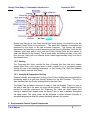
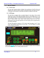
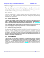
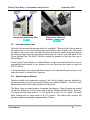
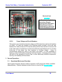
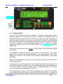
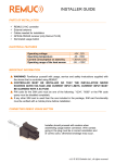
Sturdy Chick Body by Commander Industries Inc.
September 2007
1. Introduction to Environmental Control System Operations Manual
1.1. Overview
The Sturdy Key Pad Computer is designed to automatically monitor the components of
the Control System and adjust their output to control indoor air quality including:
temperature, relative humidity, carbon dioxide and oxygen in the interior of the straight
truck under various exterior and interior conditions. The primary purpose of the System
is for the control of indoor air quality while shipping live poultry.
This manual outlines the Control System and general procedures to follow during
operation, including maintenance and troubleshooting.
Figure 1
1.2. How it works – the basics
1.2.1. Air Flow
The Sturdy Chick delivery body design system has been developed over the last 25
years with the guidance and help of our many long-term customers. It is unique in the
chick delivery industry, with its exclusive patented CROSS AIR FLOW SYSTEM in
which safe and happy birds travel on journeys up to 30 hours and longer.
The air enters the vehicle through the front Damper Door. It is directed through the
Poultry Holding Area by Inlet Fans, and moves through the chicks into the sidewalls.
The sidewall air is regulated by engineered gaps in the walls to ensure even air flow
throughout the vehicle. The air is then either exhausted completely or in part through
the exhaust Doors located on the sides of the vehicle. See air flow diagram Figure 2:
Truck Manual
1
Sturdy Chick Body by Commander Industries Inc.
September 2007
Air Flow - Figure 2
Please note that the air only flows through two boxes before it is returned to the Mix
Chamber/Control Room for rejuvenation. This whole Mix Chamber is controlled and
monitored by the driver or the cab mounted Computer. The system will control
temperature and humidity to match targets set by the Hatchery Manager. Both the Mix
Chamber (with large walk-in door) and the Poultry Holding Area are the easiest to
clean and disinfect in the industry. This is made faster and easier because of the solid
floor and roof, along with our cleanout doors located approximately every four feet in
the sidewall ducts.
1.2.2. Heating
The Three-way Mix Valve controls the flow of heated fluid from the truck chassis
engine either back to the engine when no heat is called for or in a metered amount
through the rest of the heating components, i.e. the Heating Coil (Rad), the Webasto
Auxiliary Heater, and the Heat Pump.
1.2.3. Humidity & Evaporative Cooling
Relative humidity and evaporative cooling of the Poultry Holding Area are adjusted by
introducing water in a mist form through Nozzles into the Mix Chamber. The mist is
then dispersed into the Poultry Holding Area by the Inlet Fans.
The Spray Tank provides a reservoir of water to feed the Nozzles. There is a cap on
the tank to add ice to the water for more efficient cooling. When the heated mist is
needed for humidity adjustment the Three-way Mix Valve will divert heated fluid
through a sealed hose, looped inside the Spray Tank, so heat is radiated throughout
the spray water. The spray pump will be activated to either increase humidity or
decrease temperature when the sensor feedback indicates it’s needed.
2. Environmental Control System Components
Truck Manual
2
Sturdy Chick Body by Commander Industries Inc.
2.1.
September 2007
Key Pad Computer
2.1.1. Control Logic
The Key Pad Computer gathers feedback from positioning of the Mix Valve and
Damper Door, and from sensor readings, thermostat setting, and target set points.
It will adjust Control System Components as required to satisfy the set points.
2.1.2. LED Display
The Key Pad is equipped with a constant display for the status of the outside
temperature sensor, three inside temperature sensors, one humidity sensor, a volt
meter, and a position of the Damper and Mix Valve (from 0 to 100% open.) It will
also display the names of various active components when in use (i.e. Automatic
Mode or Manual Mode, Dome, Spray Pump, Auxiliary Heater and Inlet Fans).
Adjustments to the back light brightness of the LED display can be programmed by
the Hatchery Manager.
The Key Pad requires a minimum of 10.5 volts to start the system, and 11.7 plus
volts to get maximum performance from the fans. The LED Display for voltage
must be carefully monitored.
Figure 3
The Key Pad, Figure 3, allows for the user to control different modules that are connected
such as the Damper, Inlet Fan, Auxiliary Heater and more.
Truck Manual
3
Sturdy Chick Body by Commander Industries Inc.
September 2007
2.1.3. Individual Key Description:
Complete system shut down or exit from menus or
programming. Press key to turn system OFF.
Figure 4
To turn system on, use AUTO MAN key. See Figure 5 for
instructions.
Figure 5
The AUTO MAN key is used to turn the system ON. The
AUTO MAN key is also used to control the operating mode
of the system. You may select between AUTO and
MANUAL.
How To Use
•
•
•
•
•
•
If system is off, press AUTO MAN key once to turn
system on. System is ON when the LED display is lit.
Continuing to press AUTO MAN key when system is on
will alternate between Manual Mode and Automatic
Mode.
Manual Mode is ON when indicator light is OFF*. See
Figure 13 for indicator lights.
Automatic Mode is ON when indicator light is ON*. See
Figure 13 for indicator lights.
Manual Mode is controlled by the user.
Automatic Mode is controlled by the pre-set parameters
programmed by the Hatchery Manager.
*The operational mode will show in the upper right hand
corner of the Key Pad LED Display.
Opens and closes Damper. The arrow pointing up opens
the Damper and the arrow pointing down closes the
Damper. Each keystroke enables a 5% incremental opening
or closing of the Damper.
Figure 6
Figure 7
Truck Manual
Opens and closes the Mix Valve. The arrow pointing up
opens the Mix Valve and the arrow pointing down closes the
Mix Valve. Each keystroke enables a 5% incremental
opening (increase in heat) or closing (decrease in heat) of
the Mix Valve.
4
Sturdy Chick Body by Commander Industries Inc.
September 2007
Activate or de-activate the Spray Pump by pressing key. On
when indicator light is lit. When operating the word “PUMP”
will display in the LED Display.
Figure 8
Activate or de-activate the Auxiliary Heater by pressing key.
On when indicator light is lit. When operating the word
“HEAT” will display in the LED Display.
Figure 9
Activate or de-activate the Inlet Fans by pressing key. On
when indicator light is lit. When operating the word “INLET”
will display in the LED Display.
Figure 10
This function cannot be modified by the user while in
automatic mode.
Activate or de-activate the Reefer unit by pressing the key. On
when indicator light is lit.
Figure 11
The REEFER key is used only when transporting eggs, when
the outside temp is above 60 degrees Fahrenheit:
1
2
3
4
turn system to Manual Mode
turn Inlet Fans on
set Damper at 0% (Damper Door completely closed.)
set Mix Valve at 0% (completely shut off – no heat to
system.)
Activate or de-activate the Dome Lights by pressing the key.
On when indicator light is lit. When operating the word
“DOME” will display in the LED Display.
Figure 12
Truck Manual
5
Sturdy Chick Body by Commander Industries Inc.
September 2007
Indicator Lights
The indicator lights show
functions are on when lit, with
the exception of the AUTO MAN
key (see Figure 5 )
Figure 13
Other Environmental Control System Components
Dome Light
Exhaust (Outlet)
Fans
Figure 14
Mix Valve
Linear Actuator
Three-way
Mix Valve
Spray Tank (See Figure
18 for current model)
Spray Pump
Inlet Fans (See
Figure 2 for current
orientation of fans.)
Webasto Auxiliary
Heater
Heat Pump
Mix Chamber/Control Room cross section. (Note: Layout of the Control compartment has been
changed since this photo was taken. See notes under labels for Spray Tank and Inlet Fans.)
Truck Manual
6
Sturdy Chick Body by Commander Industries Inc.
2.2.
September 2007
Dome Lights
Three Dome Lights are located in the Poultry Holding Area and one Dome Light is centred
in the Mix Chamber/Control Room of the truck for lighting. The lights can be turned on
during loading/unloading, maintenance, etc. The lights are turned off by a pre-set timer.
Operational time must be programmed by the Hatchery Manager.
2.3.
Heat Pump
The Heat Pump assists in providing consistent heat to the Poultry Holding Area by
insuring that the volume of heated fluid entering the Heating Coil (Rad) is evenly
distributed from top to bottom.
2.4.
Webasto Auxiliary Heater
The diesel fired Webasto Auxiliary Heater, located on the floor in the Control Room, is
used to boost the temperature of the heating fluid coming from the chassis engine. It
works in conjunction with the external Heat Pump to increase fluid flow. See Section 2.3.
Note: the Auxiliary Heater has an internal pump that continues to circulate the fluid for one
or two minutes after the Auxiliary Heater shuts down, to allow the heater to cool.
2.5.
Heating Coil (Control Room Rad)
A custom made Heating Coil is positioned vertically in the control room in advance of the
Inlet Fans. It is the full height of the fan shroud, ensuring that air entering the Poultry
Holding Area must pass through the Heating Coil supplying even heat when required by
the system. The Heating Coil shroud on the control room side is fully open and the fan
shroud on the Poultry Holding Area side is hinged to allow easy access for inspection and
cleaning of the Heating Coil and Inlet Fans.
2.6.
Three-way Mix Valve
The Three-way Mix Valve, which is operated by a Linear Actuator, controls the flow of
heated fluid from the truck chassis engine either back to the engine, when no heat is
called for, or in a metered amount through the rest of the heating components, i.e. the
Heating Coil (Rad), the Webasto Auxiliary Heater, and the Heat Pump. Should you need
to manually run the system, use the parameters In Table 1 below to set the Mix Valve and
Damper.
Truck Manual
7
Sturdy Chick Body by Commander Industries Inc.
September 2007
Table 1 Mix Valve and Damper Control Table
2.7.
#
Outside Environmental Conditions
Damper Setting
Mix Valve
Setting
1
Outside Temperature is at target
temperature or higher
100%
0%
2
Outside Temperature is 20°F below
target temperature
50%
50%
3
Outside Temperature is more than
20°F below target temperature
10%
100%
Damper
The Damper is the top/front inlet baffle door, which regulates the amount of fresh air
allowed into the Poultry Holding Area.
Exhaust Doors act as baffles to direct air from the Poultry Holding Area either outside the
body (exhausted) or back into the Mix Chamber for re-circulation to Poultry Holding Area
along with fresh air.
The Damper Door, operated by a linear actuator, is connected to the Exhaust Doors by
two linkage rods, allowing all three doors to be opened and closed in tandem in 5%
incremental adjustments.
As the Damper opens, more fresh air is brought into the Poultry Holding Area and more
air is exhausted to the outside. As the Damper closes, less fresh air is brought in and
more air is re-circulated.
When the Key Pad Computer is set to Automatic Mode the Damper will not close less
than a minimum specified setting (to be programmed by the Hatchery Manager) to ensure
oxygen requirements are maintained.
When operating in Manual Mode, DO NOT under any circumstances operate the vehicle
with the Damper closed below 10% when the box contains chicks. See Figures 15 & 16.
Should you need to manually run the system, use the parameters In Table 1 above to set
the Mix Valve and Damper.
Truck Manual
8
Sturdy Chick Body by Commander Industries Inc.
Damper Door and Exhaust Door
Figure 15
2.8.
September 2007
Damper Door with Linear
Actuator – interior view
Figure 16
Inlet and Exhaust Fans
The Inlet Fans provide the required airflow for ventilation. There are Inlet Fans located at
the centre front of the Poultry Holding Area and Exhaust Fans located at the front along
the sides in the control room. The Inlet Fans blow air down the centre along the length of
the Poultry Holding Area and the Exhaust Fans draw air from the side wall ducts of the
Poultry Holding Area. The INLET FAN key controls the operation of the Inlet Fans only in
Manual Mode.
At start up the Control System is in Manual Mode. In this mode the Exhaust Fans turn on
automatically and continue to run, however, the Inlet Fans must be turned on using the
INLET FAN key.
In Automatic Mode, both Inlet and Exhaust Fans turn on automatically and continue to run
under the control of the Key Pad Computer.
2.9.
Spray Pump and Nozzles
Relative humidity and evaporative cooling of the Poultry Holding Area are adjusted by
introducing water in a mist form through Nozzles into the Mix Chamber. The mist is then
dispersed into the Poultry Holding Area by the Inlet Fans.
The Spray Pump provides pressure to operate the sprayers. Spray Nozzles are located
on the front wall across from the Inlet Fans in the Mix Chamber/Control Room. There are
four Spray Nozzles each rated at 1.0 U.S. gal/hr for a total of 4 U.S. gal/hr. The fresh
water holding tank for spray water is 42 U.S. gallons. The holding tank capacity will
provide continuous spraying for approximately 10 hours.
Truck Manual
9
Sturdy Chick Body by Commander Industries Inc.
September 2007
2.10. Spray Pump Pressure Tank
Water is supplied to the evaporative cooling spray system by the Spray Pump. A
Pressure Tank, set to 20 psi is installed between the pump and the Spray Nozzles to
create a reservoir of pressurized water for continuous fluid to the Spray Nozzles. This
extends the life of the pump by reducing the number of times that it cycles on and off in
providing water to the spray system.
2.11. Spray Tank
The Spray Tank requires filling when empty. Actual time of spray operation will determine
the time required to empty the Spray Tank. The tank should be refilled prior to loading an
empty truck. A spigot is located outside of the front of the unit on the passenger side to fill
the Spray Tank. Attach a water hose and fill the tank. Water will flow out of an overflow
port (and onto the ground) when the tank is full. Additionally, there is a cap on the tank to
permit the addition of ice to the water if required.
Spray Tank Refill Spigot
Figure 17
Spray Tank located inside Control Room
Figure 18
2.12. Sensors
Four environmental sensors are installed to feed back information to the Key Pad
Computer for monitoring and control. Their readings show on the Key Pad LED Display
under the following headings:
•
•
•
•
TEMP.1 - is an inside temperature sensor located near the front of the Poultry
Holding Area (passenger side).
TEMP.2 - is an inside temperature sensor located near the middle of the Poultry
Holding Area (passenger side). See Figure 20.
TEMP.3 - is an inside temperature sensor located near the back of the Poultry
Holding Area (passenger side).
TEMP.O - is an outside temperature sensor mounted inside the Control Room on
the driver side front wall just below the Damper Door. A temperature probe is
Truck Manual
10
Sturdy Chick Body by Commander Industries Inc.
•
September 2007
connected through the front wall and located outside in an aluminum protective
housing. See Figure 19.
HUMIDITY - is a relative humidity sensor located with ‘TEMP.2'. See Figure 20.
Outside temperature probe in
aluminum protective housing probe is connected to sensor
box mounted inside the control
room on the front wall directly
behind the outside probe
position.
Figure 19
Inside mounted sensors consist of
two temperature sensors and one
combination humidity / temperature
sensor. They are located inside the
access doors on the curb side of the
vehicle.
Figure 20
2.13. Electrical Panel
2.13.1.
Overview
The Electrical Panel is located in the cab of the truck. Fuses, circuit breakers and
control relays are located inside the Electrical Panel.
Truck Manual
11
Sturdy Chick Body by Commander Industries Inc.
September 2007
Electrical Panel
Figure 21
See Troubleshooting Tab for
Connections Diagram
(Electrical Panel Schematic),
Wiring Harness, Fuses &
Ratings and Fan Connection
Version Identification Chart
2.13.2.
Fuses, Relays and Circuit Breakers
This system uses standard automotive relays and ATO style fuses and circuit breakers
for safety. All fuses are located in the Electrical Panel (located in the truck cab,
between the seats) except a) 275 amp fast acting limiter fuse mounted on the fire wall
in the Cab engine compartment to protect the alternator and batteries and b) 30 amp
in-line-fuse in the power line from batteries to Auxiliary Heater.
Under no
circumstances change the value of any fuses in the panel. If a fuse repeatedly is
blowing, contact Commander Industries Technical Support. Changing values of fuses
will result in the damaging of the Key Pad, or other electrically sensitive components,
and may void warranty on these items.
3. General Operations
3.1.
Operational Modes and Overrides
The Key Pad Computer has two modes of operation: AUTO (Automatic Mode) and MAN
(Manual Mode). Selection between modes is done on the Key Pad. (See figure 22)
Truck Manual
12
Sturdy Chick Body by Commander Industries Inc.
September 2007
Figure 22
3.1.1. Automatic Mode
The Key Pad Computer should be operated in Automatic Mode during normal
operation between the times when the truck is loaded until unloading. While in
Automatic Mode, the only direct control the user has over any of the components of
the Environmental System is humidity and cooling with the Spray Pump and heating
with the Auxiliary Heater. The user should only have to monitor the sensor feedback
on the visual display. Several conditions require the user to operate the system
manually by switching the Key Pad to MAN. Refer to the ‘3.1.2.2. Section Manual
Mode below.
The Key Pad controls are inactive except: SPRAY PUMP, AUX HEATER and DOME
LIGHT keys.
The DAMPER is preset at the factory to be open at 10% at startup. This startup
default can be reset by the Hatchery Manager in 1% increments from 5% to 25%.
Opening and closing of the Damper Door is adjusted automatically by the system
afterwards.
There are four temperature sensors (one for the outside temperature and three for the
interior temperature.)
To determine the interior temperature, the Computer calculates the average of the
three interior temperature sensors. If one of the temperature sensor readings differs by
5°F with the others, it will be excluded from the average calculation. The exterior
sensor is used simply for information to the driver.
If the temperature is below or above the programmed value, the Key Pad Computer
will automatically adjust the Damper opening value and the Mix Valve to regulate the
Truck Manual
13
Sturdy Chick Body by Commander Industries Inc.
September 2007
temperature back to the pre-set value. In certain cases, the Auxiliary Heater will be
activated if the temperature is more than 5°F lower than the pre-programmed value. If
the temperature rises more than 10°F higher than the target temperature, the Spray
Pump will be activated to refresh the chicks.
The humidity control is regulated by feedback from a humidity sensor compared to the
set value programmed by the Hatchery Manager.
If the humidity is below the programmed value, the system automatically activates the
Spray Pump to increase humidity back to the pre-set value programmed by the
Hatchery Manager. Should the humidity be above the pre-set value, the sprayers will
be idle.
3.1.2. Manual Mode
3.1.2.1.
General Instructions for operations in Manual Mode
Once the Key Pad Computer is changed to Manual Mode, the operation of each of
the ventilation components are operated at the choice of the user.
1. turn on the Inlet Fans
2. adjust the Damper and Mix Valve to suit conditions (see Table 1 – Mix Valve
and Damper control table, found between Sections 2.4 and 2.5)
3. if heat is required, turn on the Auxiliary Heater.
4. turn off the Auxiliary Heater when the target temperature is reached.
5. turn Spray Pump on if the interior relative humidity is less than 50% and/or
the temperature is more than 90°F.
3.1.2.2.
Compulsory Manual Mode
Extreme changes in exterior temperature
Extreme changes in exterior temperature is considered to be more than 10
degrees in less than 15 minutes, which could happen during spring and fall, as
well as when being parked on hot asphalt.
Preheat
The Poultry Holding Area should be preheated to target temperature prior to
loading. The Auxiliary Heater will automatically turn on until the thermostat
temperature is reached. The length of time required for preheat will depend on
exterior conditions, temperatures and storage of shipping truck.
Truck Manual
14
Sturdy Chick Body by Commander Industries Inc.
September 2007
If the cargo temperature is below target, the time for preheating the Poultry
Holding Area can be decreased by steps one through four in the following order:
1. switch the control to MAN (Manual Mode)
2. turn on the Inlet Fan
3. fully close the Damper
4. fully open the Mix Valve
When the Poultry Holding Area temperature reaches pre-set temperature switch
the control to AUTO.
Control or other electrical malfunction
See Troubleshooting Guide.
Washing
The Key Pad Computer MUST be turned to OFF during washing. If required, to
decrease drying time and to prevent freezing, the following components can be
manually operated:
•
•
turn on the Inlet Fans
open the Mix Valve 100%
3.1.3. System Overrides
In the Automatic Mode the Spray Pump will only be activated if the humidity is
below the pre-set value programmed by the Hatchery Manager. The driver can
override this function by pressing the Spray Pump key even in Automatic Mode.
The driver can also override the system in Automatic Mode by turning on the
Auxiliary Heater.
System Overides
Figure 23
Truck Manual
15
Sturdy Chick Body by Commander Industries Inc.
3.2.
September 2007
Maintenance
Regular maintenance of your Environmental Control System Components is very
important to ensure optimum performance. See the Maintenance Section for schedules
and checklists.
3.3.
Troubleshooting
A variety of situations have been listed in the Troubleshooting Guide that may occur
during normal operation of the shipping truck Environmental Control System. It is
generally recommended to first check if the issue is Key Pad Computer related by
switching to Manual Mode to determine if a component will operate outside of the
Automatic Mode. If there is insufficient voltage, some components may operate in Manual
Mode but not in Automatic Mode. Follow the appropriate steps in the Troubleshooting
Guide and if you have ANY questions or concerns contact Commander Industries
Technical Support toll free (877)743-0994 for further details (General office phone number
(519)245-1386).
Truck Manual
16