1
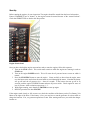
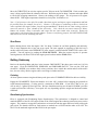
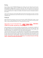
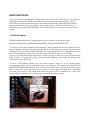
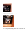
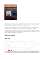
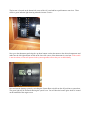
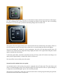
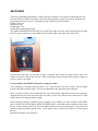
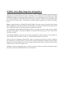
OPERATION MANUAL
FOR
Eloise
Welcome aboard our 1996 Grand Banks 42 Classic!
We are happy you have chosen “Eloise” for your vacation and take pride in sharing her with you.
We are sure you will enjoy cruising the islands of the Pacific Northwest.
These instructions are designed to make your cruise more pleasurable. In general, the operation of
the boat is fairly self-explanatory. Hopefully this will help with most of the basic operational
questions, some of which are unique to this vessel. If you have questions about the boat or about
places to visit, please do not hesitate to ask the AYC staff.
At the end of your trip please take a moment to enter your name and any comments in our guest log
located in the third drawer under the captain’s seat at the main helm. Your comments are important
to us as we continue to upgrade “Eloise” after each charter season in order to make your next trip
even more memorable.
Enjoy your trip!
TABLE OF CONTENTS
Boat Operation
Engine Inspection
Start-Up
Shutdown
Getting Underway
Cruising
Glendinning Synchronizers
Docking
Fueling
Boat Electrical
A.C. (Shore) Systems
Inverter
Generator
D.C. (House) Systems
Batteries
Sanitation Systems
Marine Toilets
Holding Tank
Y-Valve
Water Systems
Fresh Water Tanks
Fresh Water Pump
Hot Water
Electric Hot Water Tank
Everhot System
Showers
Galley
Stove/Oven
Refrigeration/ Freezer
Microwave
Heating Systems
Webasto Hydronic Heating
System Operations
Heat only option
Heat with continues hot water option
Heat only option
Electronics
VHF Radio, Depth Sounder, Radar
GPS/Plotter
Entertainment
AM/FM Radio
CD player
TV/DVD
Anchoring/Mooring Cans
Barbecue
Dinghy/Outboard
Crabbing/Fishing
Other: Bilge Pumps/Safety/Fire Extinguishers
BOAT OPERATION
Engine Inspection
Remember your “WOBBS” every morning: Water (Coolant), Oil, Bilges (Inspect and Pump-out), Belts and
Sea Strainers.
Check the water levels in the batteries. After a long day of cruising or after a couple of days on shore
power, the water levels may drop depending on temperatures and battery use. Use distilled water provided
and the battery filler container. Extremely low water can result in permanently dead batteries, so check
them often.
Check the level of COOLANT in the expansion tanks - but never when the engine is hot. Check the level
of OIL in each engine by checking the dipsticks located on each engine. Look at the etch marks on each
dipstick that indicate the proper oil level. DO NOT OVERFILL OIL! Only fill if oil levels are below the
second dip stick mark from the top. Fill to the top scratch mark if adding oil. Please use a paper towel or oil
rag to wipe off any spills. Check the general condition of the BELTS, HOSES, and FUEL LINES. Note any
new oil or fluid leaks and look for the source to make sure there is not a loose bolt or clamp that needs
adjusting.
Bilges should never have oil in them. Sometimes the water may be dark but there should never be oil
floating on the top. If you find oil, look for the source. Oil discharges, even accidental, can cause serious
fines for the boat operator.
Ensure the valve on each RAW WATER is in the ‘open’ position (lever in-line with valve).
Check the glass of each for debris. Using a flashlight to shine through the strainer will help to see the
amount of debris. If necessary, close the seacock, open the strainer cover, clean the strainer, and
reassemble. Wipe down with a rag and check for water leaks from the top of the strainer. Remember to
reopen the seacock. Check your generator RAW WATER THRU-HULL and STRAINER as well and
follow the same procedure.
Start-Up
Before starting the engines, do your inspection. The engines should be started from the lower helm station.
Ensure GEARSHIFTS are in ‘neutral’, or the engines cannot be started because of the “neutral lockout”.
Check that THROTTLES are back to the idle position.
Engine Switch Panel
Once you have checked the engine room and are ready to start the engines, follow this sequence:
1. Turn on the STOP switch. This switch must remain on while the engines are running in order to
STOP them.
2. Turn on the engine POWER switch. This will cause the oil pressure buzzer to turn on which is
normal.
3. Press the STARTING button to start the engine. Listen carefully to hear when the engine starts
over the buzzer noise and release the start button to avoid damaging the starter. Note that the buzzer
will go off until the oil pressure rises – about 10 seconds. If the buzzer does not go off in 20
seconds, push the engine STOPPING button and turn off power switch. Check engine for cause of
low oil pressure. After resolution repeat steps 1 – 3.
4. With engine running, move throttle to 700 RPM to warm up engine.
5. REPEAT procedure for other ENGINE.
If the engine cranks slowly or fails to turn over, check the condition of the battery on the Five Battery Volt
Meter to the right of the helm. If the battery is low, you may have to run the generator for a short while to
charge the batteries. If so, see generator operations to start. After starting make sure you switch the charger
breaker on.
Move the THROTTLES to raise the engine speed to 700 rpm on the TACHOMETER. Check to make sure
water is being expelled from the exhaust at the stern. Warm the engine for about 5 minutes and reduce RPM
to idle before engaging transmission. Observe the readings of the gauges. The oil pressure will register
about 60 PSI. Cold engine temperatures should rise slowly after 10 minutes or so.
Note -- If oil pressure is low after 30 seconds, shut down engine, and inspect engine compartment and look
for possible cause (for example, loss of oil.) Caution -- If an engine is overheating or there is lack of raw
water expelled in the engine exhaust, stop the engine immediately. Recheck the raw water-cooling system to
ensure the seacock is ‘open’ (handle in-line with valve). Next, check the raw water strainer for debris.
Remove the strainer, clean, re-assemble, and reopen the raw water intake valve (seacock). Restart the
engine and re-check water flow from the exhaust. If water is not flowing properly, the RAW WATER PUMP
may need to be serviced. Seek help from AYC.
Shut-Down
Before shutting down, allow the engines ‘idle’ for about 5 minutes to cool them gradually and uniformly.
This is most important after a long run at top speed. The time engaged in preparing to dock the boat is
usually sufficient. Ensure each GEARSHIFT is in the ‘neutral’ position and each THROTTLE is in the ‘idle’
position. Turn off engines by pushing the STOP BUTTONS. When the engines stop the oil pressure
warning buzzers will sound. Turn off the engine power breakers and the STOP switch.
Getting Underway
Retrieve the boarding ladder and place in the lazarette. DISCONNECT the shore power cord (see 110-Volt
next page). Close the PORTHOLES, WINDOWS, and FORWARD HATCH. Turn on your VHF and
electronics. ASSIGN crew members their various positions. Once outside the marina and out of the traffic
lane, for crew safety, idle the engines while crew brings in fenders and lines.
Cruising
All close quarters maneuvering should always take place at the FLYBRIDGE HELM for the best visibility.
Engage the GEARSHIFTS. Ensure the throttles are in the ‘idle’ position before engaging the gearshifts to
avoid transmission damage. Cruising speed is a maximum of 2000 RPM. If you run at 7Kts or less, you
will use only 2-3 gallons of diesel per hour. We have found that cruising at or around 1650 RPM’s provides
a good speed and fuel efficiency. Your speed will vary depending upon the weight and load and weather
conditions.
Glendinning Synchronizer
Eloise is equipped with Glendinning Engine Synchronizers. The synchronizer is designed to control and
match the RPM’s of the SLAVE engine to that of the LEAD engine thus reducing unnecessary stress on the
engines . The controls to engage the synchronizer are located at both the upper and lower helms with a push
pull switch. The throttle controls at each station are marked one as LEAD and the other as SLAVE. The
SLAVE is the starboard engine and the LEAD is the port engine.
After you leave your docking area or marina you may now utilize the synchronizers.
To operate:
1. Have both engines running and advanced speed slightly above idle.
2. Switch SYNCHRONIZER ON-Pilot light will be ON.
3. MOVE SLAVE ENGINE THROTTLE LEVER TO MAXIMUM SPEED POSITION-since the
SYNCHRONIZER is now controlling the slave engine, the lever is “limp” or non-effective.
Advancing the slave engine lever eliminates the SYNCHRONIZER of undue strain in moving the
entire control cable system.
4. Both engines are now under the control of a single movement of the lead engine control and may be
advanced or retarded through the entire cruising range.
5. To disengage-switch OFF SYNCHRONIZER – move engine lever back towards idle. It will
automatically re-engage with the engine control. A safety collar assures positive return to idle when
switching OFF and moving lever back.
Note – Eloise has ample power if needed should wind or currents slow your progress. Avoid engine
speeds over 2000RPM as it causes higher engine temperature, possible damage, and much higher fuel
consumption.
Docking
During docking, use the FLYBRIDGE HELM for greater visibility to the stern. While moving slowly to the
dock or mooring locations, center the WHEEL using the rudder position indicator and us only the
GEARSHIFTS and THROTTLES to maneuver the boat. Have your crew ready the lines and fenders and
give clear instructions on how you will be docking. Often times your crew will need to step off from the
swim step with the stern line. Another crew member will need to be at the bow or mid-ships to hand over
the next lines.
After you have docked retrieve the boarding ladder from the lazarette and attach the stay cable to prevent the
ladder from being knocked into the water. Run the cable from a rear cleat through the line hole not over the
varnished toe rail.
Fueling Up
OPEN FILLER CAPS located on each side of the salon with a DECK FITTING KEY (spanner wrench)
which is kept in a small compartment on the dash, to the right of the wheel and above the power panels.
There is a vent on the hull below the filler cap. It will spray fuel if you overfill.
MAKE SURE YOU HAVE THE RIGHT FUEL!
DIESEL! DIESEL! DIESEL!
DOUBLE-
CHECK! Gasoline can destroy a diesel engine!
Before pumping fuel, have an oil/fuel sorbs handy to soak up spilled fuel. You should have a rough idea of
the number of gallons you will need by checking the sight tubes on the fuel tanks in the engine room. Note
the sight tubes have valves at top and bottom that must be opened in order to get an accurate reading. Each
tank holds 300 gallons. Close sight tube valves for safety when you have read them.
If you have skin sensitivities to diesel, wear rubber gloves. Place the DIESEL nozzle into the tank opening,
pump slowly and evenly, and note the sound of the fuel flow. Pumping too fast may not allow enough time
for air to escape (even with the large fuel intake) which will result in spouting from the tank opening. As the
tank fills, the sound will rise in pitch or gurgle. The sound may indicate that the tank is nearly full. Top off
carefully, and be prepared to catch spilled fuel. Spillage may result in a nasty fine from law enforcement.
Caution -- Clean up any splatter and spillage immediately for environmental, health and deck safety
reasons. Wash hands with soap and water thoroughly.
BOAT ELECTRICAL
The electrical system is divided into two distribution systems: 110-volt AC and 12-volt DC. The systems are
controlled from the two ELECTRICAL PANELS located on the right side of the main helm. The DC
ELECTRICAL PANEL located above the AC Panel, where the BATTERY SWITCHES ARE FOUND.
When not connected to shore power, batteries are providing all power. Therefore, monitor the use of
onboard electricity with the FIVE BATTERY VOLT monitor and turn off electrical devices that are not
needed.
110-Volt AC System
SHORE POWER supports all AC equipment and receptacles on board, as well as the charger.
BEFORE CONNECTING TO SHORE POWER, MAKE SURE THE INVERTER IS OFF.
To connect to shore power, determine what amperage is being supplied from the dock connection. Then,
plug the appropriate cord (50 or 30 amp) into either the aft or forward plug location then plug into the dock
receptacle. If necessary, add a CORD ADAPTER. Cords coming off the bow can be wrapped loosely around
the bow line and should never be in the water. Most marinas provide 30 amp power not 50 amp.
If you’re on 30 amp and the dock breaker pops off when you plug in, make sure to turn off the hot water
heater and other AC outlets and try again. Hot water heater, hairdryer, coffee maker, and toaster in any
combination can pop the breaker.
At the AC ELECTRICAL PANEL, turn the selector switch to either the aft or forward position
corresponding to where you have attached the power cord. Watch the 110v ammeter for load LOCATED
RIGHT OF THE HELM BOTTOM GUAGE. If the load exceeds 30 amps, you will pop the breaker on the
dock. If this occurs, wait to turn on one of your systems (i.e. water heater) until amps drop. The charger
will often start out with a high current draw which will decrease after 10 minutes or so. After it has
dropped, add other appliances as needed, keeping total current draw under 30 amps.
If 110 outlets fail to work, check the GFI switches on the outlets to make sure that they have not been
tripped. Also make sure you have switched on the port and starboard outlet circuit breakers located on the
AC Electrical panel.
Inverter Power
The INVERTER provides AC power to the 110-volt receptacle plugs in the entertainment cabinet on the
port side rear area of the salon and powers the Webasto Heating system. The inverter panel is located on the
bottom left side of the AC power panel with an on/off push button switch. To operate the TV/DVD or the
heating system, make certain that it is on. The inverter itself is located on the starboard side strapped to the
top of the engine battery.
The inverter’s power source is the starboard engine battery located in front of the starboard engine. The
quantity of AC power is limited to the capacity of only this battery. Monitor your battery usage very
carefully! The Five Battery Volt Meter should never indicate less than 12 volts. When the inverter is not
being used for heat or TV/DVD turn it off.
Generator
The generator has an 8kw capacity and can provide enough power for all AC systems on board.
To start your GENERATOR, first check that your generator’s fluids are topped off and the raw water intake
is open. The generator controls are located on the lower 110v power panel. First turn the main generator
breaker switch to on. Second pre-heat the generator for about 15 seconds by depressing the HEATER
button. Then while still pre-heating depress the START BOTTON. Hold the switch in that position while
the generator catches. (About 5-10 seconds). Make sure water and exhaust are exiting the generator exhaust
tube on the port side just forward on the cabin door.
After generator is running, turn your AC power selector switch to generator. Then turn on AC systems as
you would on shore power one system at a time.
To turn the generator off, first take off the load by turning off AC breakers. Then turn off main AC Power
switch. Lastly kill the generator by depressing the generator STOP BUTTON until it dies.
House (12-volt) System
The house (12 volt) system draws its power from either the port or starboard engine batteries. Each battery is
rated at 1400cca and has a reserve amp hour rating of 270. When connected to shore power the battery
selector switch should be set to ALL. When at anchor or underway, set the switch to position 1.
Position #1 is the starboard battery which also has connected to it the small inverter that is used to watch
DVD’s on the TV or operate the Webasto Heating system. Position two is the Port engine starting battery.
The third battery in the system is dedicated to the generator for starting.
Note -- Do not change the position of the switch while the engines are running or the alternator diodes will
be damaged. Change positions with the engines off.
The 12 volt panel shows all the systems supported by your batteries. Battery power breakers should only be
on when needed. An exception is the Bilge pumps they should always be left on.
House Battery Bank & Switch
The two 8D engine batteries provide power for all DC systems. When disconnected from shore power, all
12-volt devices drain the house battery. Use devices as needed. The DC voltmeter on the Five Battery Volt
Meter shows the current condition of each battery by turning the selector switch from one, two or three.
When a battery bank is being charged, the voltage will read from about 13.1 volts to 14.4 volts depending
upon state-of-charge of the battery bank. When the battery bank is at rest, (that is, not being charged), the
voltmeter can give a rough indication of the state-of-charge of the battery bank.
Both engine batteries are charged by the engine ALTERNATORS while underway. The GENERATOR will
also charge the batteries providing the Charger circuit breaker is on when the generator is running.
As Eloise has just been equipped with a new state of the art charging system, the charger circuit breaker
should be left on at all times. This system will monitor the condition of the batteries and determine the need
to charge while plugged in at the doc or while underway.
SANITATION SYSTEM
Marine Toilet
This vessel is equipped with vacuflush electric toilets with a macerator overboard pump and tank watch
panel. The toilet pumps are electric and use fresh water for flushing.
It is important that every member of the crew be informed on the proper use of the MARINE TOILET. The
valves, openings, and pumps are small and may clog easily. If the toilet clogs, it is YOUR
RESONSIBILITY!
Always pump the head for children, so you can make sure nothing foreign is being flushed.
Caution – Never put paper towels, tampons, Kleenex, sanitary napkins, or food into the marine toilet.
To operate the toilets you must first make sure the FW PUMP and ELECTRIC HEAD breakers in the DC
panel are turned on. At each head location you will find a toggle switch on the cabinet face just below the
sinks. Make sure they are in the up position. To add water to the bowel, gently lift up on the foot peddle of
the toilet. When flushing, press down on the foot peddle and continue to hold down for about three seconds.
When finished you will hear the fresh water pump run for approximately 15 seconds or so. If it continues to
run, check to make sure the foot peddle is not slightly stuck allowing fresh water to continue into the bowel.
In the master stateroom head you will see the tank watch panel. The lights indicate the level of waste
material in the tank.
The system is equipped with a Y valve allowing waste to be pumped overboard. This valve is set to
discharge waste into the holding tank of the vessel and should NEVER be put in to overboard position
within U.S. waters. The fines for doing so are high so don’t go there.
If you are in CANADA that permits overboard discharge you may set the valve for overboard. To discharge
overboard see instructions in the next section heading Holding Tank
DO NOT FORGET TO SWITCH VALVES BACK BEFORE YOU RE-ENTER THE US. THIS
INCLUDES BEFORE CUSTOMS CHECKIN. FINES ARE HIGH!
Holding Tank
The sanitation HOLDING TANK holds approximately 60 gallons. Be aware of the rate of waste production.
With an overfilled tank, it is possible to break a hose, clog a vent, or burst the tank. The result will be
indescribable catastrophe and an EXPENSIVE FIX to you. Check the tank watch panel in the master head
often and empty the tank frequently to avoid this problem.
The HOLDING TANK is located in the engine room under the generator.
The holding tank is emptied in one of two ways:
#1 At the Marine Pump-Out Station, remove the WASTE CAP located on the starboard hull. Insert the
pump-out nozzle into the waste opening. Double-check your deck fitting! Turn on pump and SLOWLY
open valve located on pump out hose handle. When pumping is finished, close lever on handle and turn off
pump. Remove from deck fitting and replace the cap.
If there is a fresh water hose on the dock, rinse the tank by adding 2 minutes of water into tank.
#2 The tank’s contents can be discharged with the MACERATOR only in Canadian waters.
To discharge overboard, the through hull valve located on the starboard side hull just left of the generator
housing must be opened to discharge.
To open the valve, slightly loosen the T handle on the right side of the valve then pull the valve handle
upward to a vertical position and re-tighten the T handle.
To operate the macerator, turn the macerator pump breaker on in the DC electrical panel. Listen to the
macerator’s sound. When the pitch becomes higher, the tank is empty. Discharge may be observed on the
starboard side. It should only take a few minutes to empty the tank. Check the tank watch panel to ensure the
light indicates empty. After completion turn off the macerator breaker and close the through hull valve.
DO NOT FORGET TO SWITCH VALVE BACK BEFORE YOU RE-ENTER THE US. THIS INCLUDES
BEFORE CUSTOMS CHECKIN. FINES ARE HIGH!
WATER SYSTEM
Fresh Water Tank(s)
The FRESH WATER TANKS hold 271 gallons total and are located in the lazarette. Observe the water
level by removing a tank cap and viewing the water level. To refill the 3 tanks, remove the WATER CAPS
from the tanks located in the stern lazarette.
Just above the water tanks on the transom are two faucets, one is hot and cold fresh water and the other is
cold only. These could be used to shower down after a swim. The cold water faucet can be used as a wash
down for the anchor and chain.
Fresh Water Pressure Pump
The WATER PRESSURE PUMP is located on the port side of the engine room. Activate pump at the DC
panel by turning on the F.W. PUMP breaker. If the water pump continues to run, you are either out of
water or might have an air lock and need to bleed the system by opening up a faucet. If you run out of water
SHUT OFF YOUR HOT WATER HEATER on the AC panel. Serious damage can occur!
Water Filtration
The drinking and cooking water in the galley runs through a filtration system located on the port side in the
engine room directly below the galley. An extra filter if needed is located under the galley sink. Filtered
water is run through the cold side only. An indication that the filter needs to be changed is when while
running the cold water through the galley sink, the water runs slowly.
To change the filter first enter the engine room and on the port side next to the pressure tank, turn the ball
valve horizontal to the supply line to the water pump as show in the picture below.
Next open the faucet in the galley sink to relive any pressure in the line. Return to the engine room and using
your hands grasp the housing at the top and gently turn the filter housing counter clockwise to remove it.
Water will escape and drain down through the bilge. Replace the filter with the new one and reattach the
filter housing securely to prevent any leaks.
Close the faucet in the galley and turn the ball valve in line with the supply line as shown in the picture
below. Have someone turn the faucet on while you check to make sure the filter housing is not leaking.
Electric Hot Water Tank
The AC electric HOT WATER HEATER has an 18 gallon capacity tank and is available when connected to
shore power or via the generator. To use on shore power or generator, flip on the water heater circuit
breaker on the AC electrical panel. Do not use the water heater if the water tank level is very low. As with
any electric hot water tank it takes some time to get the water up to temperature from a cold start.
Everhot Tank
Hot water can also be obtained by utilizing the Everhot system located next to the AC hot water tank on the
port side of the engine room. This tank colored RED is an integral component used in the Webasto Hydronic
Heating system. Refer to that section to understand how to utilize its capabilities.
Shower
Before taking a SHOWER, make sure the F.W. PUMP and shower DRAIN PUMP breakers are on. In each
shower stall there is a silver drain knob that activates the drain pump under each floor grate. Make sure you
pull this ON prior to showering. This pump works automatically when the water level reaches the float lever.
While taking a shower, if the pump fails to operate, check for hair or debris blocking the float lever. If all is
clear make sure the shower DRAIN PUMP breaker is switched on. To help conserve water take short
“boat” showers (turning off water between soaping up and rinsing by turning the water on and off with the
flow control located at the top of each shower hose connection). To keep shower tidy wipe down the shower
stall and floor. Check for accumulation of hair in the shower and sink drains. After use, turn off the DRAIN
PUMP breaker and ensure that the faucets and nozzle are completely off after use.
GALLEY
Stove/Oven
The stove top and oven are 110 volt electric and can only be operated via shore power or generator. The two
front burners are 1100 watt each and the back burner is 550 watt and runs on high.
When using the stove top or oven, be sure to turn on the DC breaker labeled GALLEY VENT. The switch
to turn on the vent is located directly above the stove top.
Microwave
The microwave only runs on 110 AC while connected to shore power or via the generator.
Trash Compactor
The Broan trash compactor only runs on 110 AC. To open the compactor move the small white lever at the
top of the compartment to the left and then pull open the bin. See how the bag is set in the container so you
know how to install the new one if needed. To shut the bin move the white handle to the left while closing
the door. To compact turn the selector knob clockwise. Do not try and compact the trash unless the bag is at
least half full. Bag removal is accomplished by pulling the bin out then releasing the lower and upper door
latch mechanisms. The door front can now be opened allowing the bag to be removed forward and out,
rather than up and out. Place new bag in, shut door and latch the door locks and close the bin.
Extra bags can be found under the main galley sink cupboard.
Refrigerator/Freezers
The refrigerator/Freezers are Grunert 110 AC cold plates. There are two, one on the port side in the galley
and the other on the starboard side of the galley. There is a temperature gauge in the front of each showing
the current inside temperature. These are preset to a temp., which would be normal for refrigeration.
However, you may adjust the temperature to meet your individual needs. The temperature dials are located
inside each unit. As the cold plates are on the bottom of each unit, it is not advisable to place food there as it
may freeze. If you wish to use one as a freezer I would recommend the one on the starboard side. Turn the
temperature dial found on the inside of the unit to 3 and give it time to reach its maximum temperature at
that setting. As these units only run on AC limit the opening of the doors to conserve the cold. These units
should be able to keep your food at the desired temp for approximately 48 hours before you need to connect
to shore power or use the generator to cool them again.
Note: After you have opened the door to the refrigerator the outside temperature gauge may read
higher than normal. This is due to it reading cabin temperature while the door was open. It will go
back to what the inside temperature is within approximately 10 minutes.
Note: When connected to shore power or running the generator remember to turn the refrigeration
breaker on, found in the AC electrical panel.
Note: During operations of the refrigerators, it is normal to see water being discharged on the port
side of the boat. This is the cooling system pumping water through the compressor.
HEATING SYSTEM
Webasto Hydronic Heating System
Eloise is equipped with a 45k Btu Hydronic heating system. Hydronic heating is much the same as you find
in your car. Meaning that it is a closed system where coolant runs throughout a series of lines to radiators
where fans then blow across coils providing heat.
There are four heating units located in the following areas:
1. Under the forward v-birth. Fans blow heat out through a vent behind the small louvered door by the
floor and through a small vent located in the forward head. The fan controls are located below the
port side bunk.
2. Two units in the main salon. One with a heat and return air vent under the step to the starboard door,
and the other under the aft salon seat. This also has a heat and return air vent. The fan control for the
unit under the step is located under the thermostat next to the starboard door exit. The fan control
for the unit locate under the salon seat is on the port side of the seat by the entrance to the master
stateroom.
3. The last unit is located under the stairs leading to the master stateroom. There is a vent under the
stairs, one vent in the main shower and one in the main head. The fan control is on the starboard side
of the stairs in the master room.
In addition to the heating units there is an expansion tank located under the black inspection port located in
the corner of the main salon seat and an Everhot tank for hot water located next to the electric water tank on
the port side engine room.
As this is a closed system and professionally maintained and requires special coolant, there is no need to
check coolant levels in the expansion tank. If there is any questions as to the operation or perceived
problems please call AYC for assistance.
System Operations
Prior to operating the system, understand that there are three functions that can be achieved. First determine
which of these you want to accomplish.
1. You want heat only.
2. You want heat with continues hot water.
3. You want continues hot water only.
Heat only option:
To operate the system for heat only follow these steps.
First in all three cases the inverter must be on. The inverter provides AC power to the circulating pump and
temperature sensors. If the inverter is not on the system will not work. Remember the inverter runs off of
only on battery and is limited to the charge condition of it. Monitor your usage and occasionally check the
condition of batter charge.
The inverter is located on the bottom left corner of the AC panel and has a push button to turn it on. There
will be a green indicator light showing when the inverter is active.
Next go to the thermostat and using the up down buttons set the thermostat to the desired temperature and
make sure the left/right off/heat switch on the lower left corner of the thermostat is set to heat. If the switch
is not set to heat, no fans will operate in the system regardless of how they are set individually.
Now activate the heating system by switching the System Heat switch from the off position to system heat.
The green light will be activated showing the system is on. You will hear the burner ignite which is located
on the starboard of the engine room.
While the system is heating the coolant, go to each of the fan control switches and set them to either high or
low. We recommend this so that each unit is providing heat which in turn makes for more even heating
throughout. If you do not want a particular unit heating simply turn the switch to off.
The system will run for approximately 10-15 minutes before the fans automatically start running. There are
internal temperature sensors that require the coolant to be at a certain temperature before this happens.
Once the thermostat has reached the desired temperature, the boiler will shut down and the fans will
continue to run. When the areas temperature drops slightly the burner will re-ignite thus heating the coolant
again to maintain the desired temp.
To shut the system down, switch the system heat switch to off. The system will continue run during a cool
down period of approximately 5 minutes after which it will turn off.
Next turn off the inverter which powers the system.
System heat with continues hot water option.
As mentioned earlier in this section, the system is equipped with an Everhot tank. This tank allows cold
water to circulate through its forty feet of internal copper coil to heat water the water as it passes through. It
is temperature controlled through a special valve located by the tank.
The typical use of this tank is when you’re moored on the hook or mooring ring and running the generator
for the electrical hot water tank is not practical.
To operate the system for heat and continues hot water follow these steps.
First complete all the steps previously defined for heat only. The difference for this function is setting up the
Everhot tank for operation rather than the electric hot water tank.
After completing all the previous steps go to the engine room and locate the water directional valve in front
of the electric water tank. See the photo below.
Make sure the water diverter valve is in the direction shown. This allows water to go directly from the
Everhot tank to all hot water faucets throughout the boat. When docked and utilizing electric power and the
electric hot water tank, return the directional valve to the electric engine position.
Remember to watch your water usage carefully when using the Everhot system as hot water is continues
unlike the electric tank which will run out of hot water after prolonged use.
Continues hot water only option.
To set up this option make sure the inverter is on.
Next, turn the left/right off/heat switch on the lower left corner of the thermostat to the off position. By
doing this you telling the system you do not want any forced air heat produced by running the fans in the
heat units.
Now activate the system as before by switching the system heat switch from off to system heat. The green
light will light indicating it’s on. You will hear the system ignite and the system will start to heat the
coolant. As before it will take approximately 10-15 minutes before the coolant reaches temperatures needed
to heat the water.
As shown in the previous section, make sure the water directional valve is turned to the Everhot position.
When operating the system in this mode there is no heat distributed though the fan systems, only hot water is
provided. If you want to revert back to having heat with this option simply switch the left/right off/heat
switch back to heat. You can now run the heater fans.
ELECTRONICS
All electronic manuals are located in the third drawer under the lower helm captain’s seat.
VHF Radios
There are 2 VHF RADIOS. The first is located above the main helm. This radio (ICOM 506) is equipped
with an AIS receiver which displays those vessels in the immediate area who are trans ponding their vessel
identification. Make sure the VHF breaker located at the DC panel is on. There is a second VHF RADIO
(ICOM 506) located at the fly bridge helm cabinet. This radio does not have the AIS receiver function. See
radio instruction manual for operations assistance.
Depth Sounder
There are DEPTH SOUNDERS, at each helm and provide current water depth. This vessel draws 4 ½ feet of
water.
Remember to ALWAYS consult your charts for depth while underway!
Radar
To operate the integrated SIMRAD RADAR, please refer to the radar operations manual. Remember you are
not allowed to travel in FOG, at night or in serious wind conditions. To power up make sure the radar
breaker is turned on.
Autopilot
The SIMRAD AP28 auto pilot is a useful navigation aid, but DOES NOT under any circumstance replace a
human navigator. Please see user manual for operation instructions. To power up make sure the auto pilot
breaker is turned on.
Multifunction Chart Plotter
The NSS evo2 is a multifunction touch screen display navigation aid. Please refer to the NSS evo2
operations manual on how to use. To power up make sure the plotter breaker is turned on.
Note -- GPS is considered a navigation aid. Do not rely on it. Compasses, charts, and dividers are the
tools to plot position, course, and speed.
ENTERTAINMENT SYSTEMS
AM/FM Stereo Radio
The stereo unit is located aft of the port door in the cabinet lower shelf. It operates like a normal car radio.
There are two speakers (stereo) in the salon, two (stereo) in the master state room and two (stereo) on the
bridge. The Clarion is a multi-functional system which includes, CD viewing, IPOD interface, AM/FM
stereo, etc. To power the system, turn all three STEREO breaker switches on, which are located on the DC
power panel. See Clarion user manual for operation instructions if needed.
TV/DVD
A TV/DVD is located aft of the port door in the cabinet lower shelf. The TV provided to be used for DVD
movies. Follow the instructions located with the TV to operate the DVD. This device when underway must
be used with the inverter.
ANCHORING
The primary WORKING ANCHOR is a 45kg CQR and is attached to 225ft chain passed through the deck
from the CHAIN LOCKER. The locker can be accessed through the v-berth in cases where the chain gets
tangled and needs to be released. The chain has been marked in 50 foot increments.
Double Yellow=50’
Double Red=100’
Double Black=150’
Double White with Red paint=200’
The WINDLASS REMOTE SWITCHES are located on the right side of the main helm and at the fly bridge
helm. First turn on the power to the windless at the windless panel to the right of the lower helm.
Second release the keeper on the chain tray and if using the foot controls, tap gently on the ‘down’ foot
control to lower the anchor past the roller. When using either helm position use the up/down switches to
release or retrieve the anchor.
Let out sufficient ANCHOR CHAIN before setting the anchor.
If the anchorage is crowded put down at least a 3 to 1 scope (60 feet for 20 feet of water), back the anchor
in with a short burst from the engine. Then let out additional scope dependent upon conditions.
There is a gold and white colored anchor harness in the forward deck compartment with a brass snap-hook.
Attach the hook to the chain and each of the line ends to a bow cleat. Release more chain until it is slack
and the harness is bearing the anchor weight.
Before raising the anchor, ALWAYS start the engines as the windlass uses large amounts of BATTERY
power. DO NOT PULL THE BOAT WITH THE WINDLASS! As the boat moves toward the anchor, press
the ‘up’ control to take up slack line. Give the windlass short rests as you are pulling it up. Place yourself in
position to guide the anchor onto the roller. As the anchor rises, be careful not to allow it to swing against
the hull.
Reconnect the keeper in the chain tray.
Note: If the anchorage bottom is muddy, please rinse the chain as it come up by attaching the water
hose with the nozzle to the after water outlet. Turn on the cold water and rinse the chain while
removing any debris as it comes up.
A SPARE ANCHOR is stowed in the aft lazarette with a spare chain and anchor rode. Attach the rode
securely to the chain shackle before using. There is 25 feet of chain and 175 feet of nylon line.
Mooring Cans
The State Park Sticker on your vessel allows you to pick up the MOORING CANS in the parks for free.
You only need to register at the kiosk usually located at the heads of the docks. Mooring cans have a metal
triangle at the top upon which is a metal ring. The metal ring is attached to the chain which secures your
boat. IT IS VERY HEAVY. The strongest member of your crew should be picked for this job.
Come up to the CAN into the wind as you would for anchoring. Have crew members on the bow, one with a
boat hook and one with a mooring line secured like a bow line. As you are coming slowly up to the can
have the crew holding the boat hook point at the can with the hook so the skipper always knows where it is.
Hook the can and bring the ring up to the boat to allow the second crew to thread the ring with the line.
Release the hold with the boat hook. If your mooring line is led out the starboard chock bring the end of the
line back through the port side. You will essentially create a bridle with about 10 feet of slack from the
chalk to the can. The boat hook can be found in the lazarette.
BARBECUE
The BARBECUE is attached to the aft rail.
After removing the protective cover and placing it in the main cabin, attach the propane regulator found in
the small compartment located in the upper right of the lower helm. Attach a propane bottle and carefully
light the unit, preferably with a long-stem butane lighter. After the barbecue has cooled and all grease has
been wiped off, retrieve the cover from the main cabin, remove the regulator and place it over the barbeque
and tighten the draw strings so it does not blow off.
Note: Propane bottles are not stocked by AYC. You will need to purchase one. Caution -- For safety
reasons, do not store an opened propane bottle within the salon or engine compartment. Chances are these
will leak slightly once opened and propane gas could settle into low spaces. Store propane bottles in the
bow storage compartment. Ensure gasoline and flammable materials are not near the barbecue when in
use.
DINGHY & OUTBOARD MOTOR
The DINGHY is stored above the aft cabin. There is a 20hp 4 stroke Honda engine attached that is
professionally maintained. There should be no need for you to add any fluids to the motor. The dinghy
has a capacity of about 500 pounds (motor, equipment, and people – see capacity notice posted on dinghy).
First make yourself familiar with the mast-and-boom hoist on the stern. Be able to raise and lower the boom
and the D-Ring on the boom tackle. The dinghy can be lifted by a combination of lifting the boom and using
the electric winch on the boom. Note the boom stay lines and how to manage them and where to cleat them.
To ready the dinghy, clip the dinghy harness to the two dinghy bow rings and the two transom rings.
Raise the boom to about a 45degree angle. Release the boom stay lines. Release enough line from the boom
tackle with the electric winch, to allow the boom D-ring to connect to the dinghy harness lift ring. Once
attached, raise the dinghy using the boom winch, not the boom lift. Once the dinghy is clear have a crew
member pull one of the boom stay lines to swing the dinghy over the side railing. Once in position, cleat
that boom stay line to the mid-ship cleat.
Lower the boom until it is level. If needed, release more boom tackle line to lower the dinghy to the water.
Attach the dinghy painter to the railing and disconnect the D-Ring from the dinghy harness. Bring the boom
back to center position and re-attach the stay lines to their port and starboard cleats.
When towing your dinghy, always keep it tight to the boat any time that you slow down or stop, Assign one
of your crew members as the “dinghy” person to be responsible for taking up slack. You don’t want to wrap
a propeller.
Note: NEVER LAUNCH THE DINGHY WITH ANYONE ABOARD IT!
Coast Guard regulations state that any child 14 and under must wear a life jacket in a dinghy.
It is a good idea for EVERYONE to follow this rule.
CRABBING & FISHING
Always check the fishing and crabbing requirements before you leave on your cruise. You will need a
license. Many areas are CLOSED to crabbing and fishing on certain months.
CRAB AWAY FROM THE BOAT! Lines can get wrapped around props. Place your bait in the crab bait
container found inside the crab pot. Next catch crabs! Measure the crabs using the CRAB MEASURING
GAUGE normally located with the crab pot. Keep the male crabs of proper size (usually 6 ¼ inches across
the carapace). In the main salon under the forward portion of the starboard settee there is a large crab
cooker. To retrieve lift the cushion and pull the pot out. As the stove is electric and it take a very long time
to boil a large pot of water, try using the steaming method it works much faster works well. Fill the pot with
just enough water to reach the bottom of the basket insert. Bring that to a boil then place your clean or whole
crabs into the pot and place the lid on. Bring the water to a boil again and cook for about 12 minutes
depending on the amount of crab being cooked. Remember to keep an eye on the water level within the pot
so as not to boil it out before cooking is complete.
After using, wash equipment thoroughly with fresh water (available from the aft shower faucet). Note -Please do not store wet rings and gear inside the boat.
OTHER: Safety/Bilge Pumps/Fire Extinguishers
SAFETY should be paramount in your daily cruising. A MAN OVERBOARD DRILL should be discussed
and perhaps even practiced with a life jacket. Remember your life jackets are stowed under the fly bridge
windshield and under the fly bridge starboard long settee. A few should always be out and ready. Your
flares, safety equipment, air horn, and spare horn are located in a plastic container in the small cabinet under
the captain’s seat starboard side. The cabinet also includes medical emergency kits and other emergency
items.
Eloise is equipped with two AUTOMATIC BILGE PUMPs. The master switch is located on the electrical
panel. Normally, the switch will be left in the AUTO position. You may occasionally hear the pump operate
due to condensation and water from the shaft log accumulating in the bilge.
An AUXILIARY HAND OPERATED BILGE PUMP is operated in the main cabin using the handle
provided for that purpose. The pump and handle are under the starboard entry step. This is used only in
emergency situations.
The ENGINE SPARES are stowed in the aft engine compartment in plastic containers. This includes raw
water impellers, belts, fuel filters, oil filters, oil, coolant and small tools to remove filters.
There are four fire extinguishers aboard Eloise. These are all purpose types used in most fire conditions.
One extinguisher is located on the aft wall of the salon, another located on the starboard side on the master
stateroom, one located under the stairs of the forward stateroom and lastly one located to the left of the
engine room access door in the engine room.
In addition to the fire extinguishers there are three fire detectors located in each of the staterooms and the
main salon, with carbon monoxide detectors in each stateroom.