1
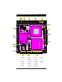
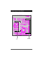
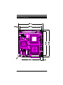
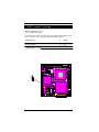
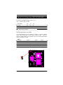
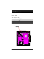
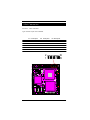
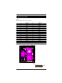
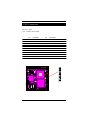
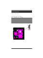
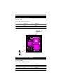
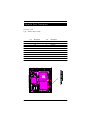
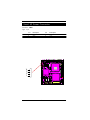
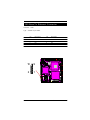
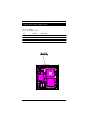
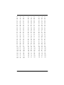
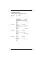
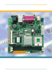
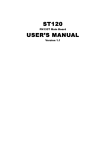
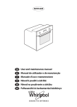
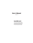
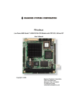
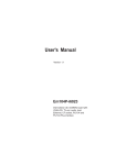
User's Manual
Version 1.1
Em104-i613
PC/104 Embedded Intel Celeron ULV 400/
650MHz CPU Model with one SODIMM up
to 512 MB SDRAM, CRT/Flat Panel
SVGA, one Realtek 8100BL Fast Ethernet
Copyright © 2003
All Rights Reserved.
The information in this document is subject to change without prior notice in
order to improve the reliability, design and function. It does not represent a
commitment on the part of the manufacturer.
Under no circumstances will the manufacturer be liable for any direct, indirect,
special, incidental, or consequen-tial damages arising from the use or inability
to use the product or documentation, even if advised of the possibility of
such damages.
This document contains proprietary information protected by copyright. All
rights are reserved. No part of this manual may be reproduced by any
mechanical, electronic, or other means in any form without prior written
permission of the manufacturer.
2
Em104-i613 User's Manual
Warning
Single Board Computers and their components contain very delicate
Integrated Circuits (IC). To protect the Single Board Computer and its
components against damage from static electricity, you should
always follow the following precautions when handling it :
1. Disconnect your Single Board Computer from the power source when you
want to work on the inside
2. Hold the board by the edges and try not to touch the IC chips, leads or
circuitry
3. Use a grounded wrist strap when handling computer components.
4. Place components on a grounded antistatic pad or on the bag that came
with the Single Board Computer, whenever components are separated
from the system
5. The standard package comes with "CPU fan" and "Heat Sink", which uses
for reducing CPU temprature. Please note you can only use one of them at
the same time and cooling effectiveness of CPU fan is better than heat
sink.
6. The "Northbridge" needs the Heat Sink or fan on it.
Technical Support
If you have any technical difficulites, please consult the user's manual first
at:
ftp://ftp.arbor.com.tw/pub/manual
Please do not hesitate to call or e-mail our customer service when you still
can not find out the answer.
http://www.arbor.com.tw
E-mail:[email protected]
Em104-i613 User's Manual
3
Table of Contents
Technical Support ...................................................................... 3
Specifications ............................................................................. 6
General Specifications .......................................................................................... 6
High Speed Multi I/O ............................................................................................... 6
Network Interface Controller ................................................................................. 6
Environmental and Power ..................................................................................... 7
Board Layout Top View (Front) .................................................. 8
Board Layout View (Back) ......................................................... 9
Board Dimension ...................................................................... 10
Jumper/Connector Quick Reference ....................................... 11
Jumper/Connector Quick Reference ....................................... 12
CMOS Jumper Settings ............................................................ 13
Serial Port Selection (RS232C/422/485) ................................... 14
RS-422/485 Mode on COM2 ................................................................................ 14
CPU Fan Connector .................................................................. 15
LAN LED Connector .................................................................. 16
VGA Connector ......................................................................... 17
Flat Panel VGA ......................................................................... 18
COM1 & COM2 Connectors ....................................................... 19
COM1 RS-232 ...................................................................................................... 19
COM2 with RS-232/422/485 Mode ..................................................................... 19
Enhanced IDE Connector ......................................................... 20
FDD Connector .......................................................................... 21
USB Connector ......................................................................... 22
Infrared (IR) Connector ............................................................. 23
Keyboard & PS/2 Mouse ........................................................... 23
4
Em104-i613 User's Manual
Parallel Port Connector ........................................................... 24
Small 4P Power Connector ...................................................... 25
100 Base-Tx Ethernet Connector .............................................. 26
Switches and Indicators ........................................................... 27
System Resources .................................................................... 28
Watchdog Timer ....................................................................... 31
Timeout Values ..................................................................................................... 31
Timeout Table ....................................................................................................... 31
Em104-i613 User's Manual
5
Specifications
General Specifications
• CPU : Intel Ultra Low Voltage Embedded Celeron 400/650MHz processor
with FSB 100 MHz uBGA package.
• Chipset : VIA VT8606 North Bridge, VIA VT82C686B South Bridge
• Display Controller : VIA 8606 Integrated Savage4 2D/3D Video Accelerator, 32MB Shared Memory, 4 x AGP
• Extensive LCD Support : 2 x 20 pin DF13 connector, supports LCD
display TTL
• BIOS : AWARD® Flash BIOS
• Green Function : power saving supported in BIOS. DOZE / STANDBY
• L2 Cache : Integrated on CPU die (256 KB)
• DRAM Memory : One 144-pin SODIMM socket supports up to 512MB
• IDE Interface : 44-pin connector x 1 (IDE supports DMA33)
• Real Time Clock : RTC with Lithium Battery
High Speed Multi I/O
• Chipset
: VIA VT82C686B
• Serial Ports : Two high speed COM ports, one is high speed RS-232C
and the other is RS232C/422/485 port (jumper selectable). Both with
16C550 compatible UART and 16 byte FIFO.
• USB : 2 onboard USB ver 1.1 ports
• Extension Bus : PC/104
• Flash EPROM : 2MB EPROM and combined BIOS support
• Watchdog Timer : 1 - 127 sec, system reset
6
Em104-i613 User's Manual
Network Interface Controller
• Chipset : Realtek 8100BL chip
• Interface : IEEE802.3U compatible 10/100 Base-T interface includes
software driver and boot ROM function
SSD Interfaces
• Compact Flash Card (CFC)
- Compact Flash Socket : supports Type I/II CFC
- Capacity : up to 1 GB CFC
Environmental and Power
• Power Requirements : +5 V @ 2.1 A (typical);(ULV Celeron 400MHz
and 512MB SDRAM)
• System Monitoring and Alarm : CPU and System temperature, system
voltage .
• Board Dimensions : 90mm x 96mm (3.5" x 3.8")
• Board Weight : 0.11kg
• Operating Temperature : 0 to 60°C (32 to 140°F)
Em104-i613 User's Manual
7
Board Layout Top View (Front)
2
3
4
5
6
7
8
1
9
10
18
11
17
16
15
14
8
13
12
1. PWR1
6. SIR1
11. LPT1
16. LAN1
2. J5
7. VGA1
12. LCD1
17. J1
3. FAN1
8. PC 104
13. COM2
18. IDE1
4. LLED1
9. USB1
14. COM1
5. JFRT1
10. FDD1
15. KBM1
Em104-i613 User's Manual
Board Layout View (Back)
CFD1
Em104-i613 User's Manual
SODIMM1
9
Board Dimension
10
Em104-i613 User's Manual
Jumper/Connector Quick Reference
Jumpers
Label
Function
J1
Clear CMOS
J5
COM2 RS-232/422/485 Selection
Em104-i613 User's Manual
11
Jumper/Connector Quick Reference
Connector
Label
Function
VGA1
VGA Display Connector
LCD1
18&24 Bit LCD Connector (DF-13 40 pin)
IDE1
IDE Hard Drive Connector
CFD1
Compact Flash Connector
USB1
USB 0-1 Connector
SIR1
IrDA Connector
KBM1
Keyboard and PS/2 Mouse Connector
FDD1
Floppy Drive Connector
LPT1
Parallel Port Connector
COM1
COM1 RS-232 Serial Port Connector
COM2
COM2 RS-232/422/485 Serial Port Connector
PWR1
Small 4P Power Connector
LAN1
100 Base-Tx Ethernet Connector
LLED1
LAN LED
JFRT1 (1-2)
Front Panel (Reset Switch)
JFRT1 (3-4)
Front Panel (External SMI)
JFRT1 (5-6)
Front Panel (HDD LED)
JFRT1 (7-8)
Front Panel (External Speaker)
12
Em104-i613 User's Manual
CMOS Jumper Settings
CMOS Operation (J1)
Type : onboard 3-pin header
If the Em104-i613 refuses to boot due to inappropriate CMOS settings here is
how to proceed to clear (reset) the CMOS to its default values.
CMOS Setup (J1)
J1
Status
Normal Operation
1-2
ON
2-3
ON
Clear CMOS
default setting
1-2 ON
3
2
1
J1
Em104-i613 User's Manual
13
Serial Port Selection (RS232C/422/485)
RS-232C/422/485 Mode select (J5)
Type : onboard 6-pin(2*3) header
J5 Selection
RS-232C
1-2
ON
3-4
OFF
5-6
OFF
RS-422
OFF
ON
OFF
RS-485
OFF
OFF
ON
default setting RS-232C
RS-422/485 Mode on COM2
The onboard COM2 port can be configured to operate in RS-422 or RS-485
modes. RS-422 modes differ in the way RX/TX is being handled. Jumper J5
switches between RS-232C or RS-422/485 mode. All of the RS-232C/422/485
modes are available on COM2.
COM2
Pin Defined:
RS-232C
RS-422
RS-485
Pin1 :
DCD
Tx+
RTx+
Pin2 :
RXD
Tx-
RTx-
Pin8 :
CTS
Rx+
x
Pin9 :
RI
Rx-
x
1
3
5
14
2
4
6
Em104-i613 User's Manual
CPU Fan Connector
Connector : FAN1
Type : onboard 3-pin wafer connector
Pin
Description
1
FAN_CTL
2
+5V
3
GND
321
CPUF1
Em104-i613 User's Manual
15
LAN LED Connector
Connector : LLED1
LAN LED can be indicated when the Network is on or off.
Type : Onboard 4-pin header
Pin
Description
1
ACTLED-
2
+3.3V
3
LINKLED-
4
+3.3V
1
16
Em104-i613 User's Manual
VGA Connector
Connector : VGA1 Connector
Type: Onboard 16-pin mini boxheader
Pin
Description
Pin
Description
Pin Description
1
RED
6
GND
1 1 NC
2
GREEN
7
GND
1 2 VDDAT
3
BLUE
8
GND
1 3 HSYNC
4
NC
9
Vcc
1 4 VSYNC
5
GND
10
GND
1 5 VDCLK
16
NC
2
1
Em104-i613 User's Manual
16
15
17
Flat Panel VGA
LCD1
Type : Onboard 40-pin DF13 Connector
Pin
1
3
5
7
9
11
13
15
17
19
21
23
25
27
29
31
33
35
37
39
Description
VCC5V
GND
VCC3V
NC
FPD0
FPD2
FPD4
FPD6
FPD8
FPD10
FPD12
FPD14
FPD16
FPD18
FPD20
FPD22
GND
SHFCLK
M(DE)
ENABLK
Pin
2
4
6
8
10
12
14
16
18
20
22
24
26
28
30
32
34
36
38
40
Description
VCC5V
GND
VCC3V
GND
FPD1
FPD3
FPD5
FPD7
FPD9
FPD11
FPD13
FPD15
FPD17
FPD19
FPD21
FPD23
GND
VSYNC
HSYNC
ENAVEE
LCD1
1
18
Em104-i613 User's Manual
COM1 & COM2 Connectors
COM1 RS-232
Connector : COM1
Type : Onboard 10-pin header
Pin
Description
Pin
Description
1
DCD1
2
RXD1
3
TXD1
4
DTR1
5
GND
6
DSR1
7
RTS1
8
CTS1
9
RI
10
NC
COM2 with RS-232/422/485 Mode
Connector : COM2
Type : onboard 10-pin header
Pin
Description
Pin
Description
1
DCD2(422TXD+/485DATA+)
2
RXD2(422TXD-/485DATA-)
3
TXD2
4
DTR2
5
GND
6
DSR2
7
RTS2
8
CTS(422RXD+)
9
RI(422RXD-)
10
NC
2
1
2
1
COM1
Em104-i613 User's Manual
COM2
19
Enhanced IDE Connector
Connector : IDE1
Type : Onboard 44-pin box headers
Pin
Description
Pin
Description
1
#RESET
2
GND
3
D7
4
D8
5
D6
6
D9
7
D5
8
D10
9
D4
10
D11
11
D3
12
D12
13
D2
14
D13
15
D1
16
D14
17
D0
18
D15
19
GND
20
NC/(Vcc)
21
REQ
22
GND
23
IO RWITE
24
GND
25
IO READ
26
GND
27
IO READY
28
GND
29
DACK
30
GND
31
IRQ14
32
NC
33
ADDR1
34
ATA66 DETECT
35
ADDR0
36
ADDR2
37
CS#1
38
CS#3
39
IDEACTP
40
GND
41
VCC(+5V)
42
VCC(+5V)
43
GND
44
NC
1 2
20
Em104-i613 User's Manual
FDD Connector
Connector : FDD1
Type : Onboard 20-pin header
Pin
Description
Pin
Description
1
GND
2
Drive density select 0
3
GND
4
NC (Key)
5
GND
6
Drive density select 1
7
#Write data
8
#Index
9
#Write gate
10
#Motor enable A
11
#Track 0
12
#Driver select B
13
#Write protect
14
#Driver select A
15
#Read data
16
#Motor enable B
17
#Head select
18
#Direction
19
#Disk change
20
#Step
21
Em104-i613 User's Manual
21
USB Connector
Connector : USB1 connector
Type:onboard Two 8-pin box headers
Pin
Description
Pin
Description
1
+5V
2
+5V
3
USBD0-
4
USBD1-
5
USBD0+
6
USBD1+
7
GND
8
GND
9
GND
10
NC
10
9
2
1
USB1
22
Em104-i613 User's Manual
Infrared (IR) Connector
Connector : SIR
Type : SIR1: onboard 5-pin header
Pin
Description
Pin
Description
1
3
5
+5V
IRRX
IRTX
2
4
NC
GND
1 2 3 4 5
SIR1
6
5
4
3
2
1
KBM1
Keyboard & PS/2 Mouse
Connector : KBM1
Type : KBM2: onboard waver 6-pin
Pin
Description
Pin
Description
1
3
5
KB_DATA
MS_DATA
+5V
2
4
6
GND
KB_CLK
MS_CLK
Em104-i613 User's Manual
23
Parallel Port Connector
Connector : LPT1
Type : Onboard 20-pin header
Pin
Description
Pin
Description
1
#STROBE
2
#Auto feed
3
PTD 0
4
#Error
5
PTD 1
6
#Initialize
7
PTD 2
8
#Select Input
9
PTD 3
10
GND
11
PTD 4
12
GND
13
PTD 5
14
NC (KEY)
15
PTD 6
16
Busy
17
PTD 7
18
Paper Empty
19
#Acknowledge
20
Select
21
24
Em104-i613 User's Manual
Small 4P Power Connector
Connector : PWR1
Type : 4 pin
Pin
Description
Pin
Description
1
+5V
2
GND
3
GND
4
+12V
4
3
2
1
Em104-i613 User's Manual
25
100 Base-Tx Ethernet Connector
Connector : LAN1
Type : onboard 10-pin header
26
Pin
Description
Pin
Description
1
3
5
7
9
TX+
RX+
NC
NC
GND
2
4
6
8
10
TXNC
RXNC
NC
10
9
2
1
Em104-i613 User's Manual
Switches and Indicators
Connector : JFRT1
Type : onboard 8-pin header
Pin
Jumper
Description
1-2
RES
Reset
3-4
ESMI
External SMI
5-6
HDD
Pin-5 is "HDD+",Pin6 is "HDD-"
7-8
SPEAKER
Pin-7 is "SPEAKER+",Pin-8 is "SPEAKER-"
1
Em104-i613 User's Manual
HDD SPK
ESMI
-+ -+
RES
8
27
System Resources
Interrupt Assignment
IRQ Address
Description
0
System Timer
1
Standard 101/102-Key or Microsoft Natural Keyboard
2
Programmable Interrupt Controller
3
Communications Port (COM2)
4
Communications Port (COM1)
5
IRQ Holder for PCI Steering
5
VIA Tech 3038 PCI to USB Universal Host Controller
6
Standard Floppy Disk Controller
7
ECP Printer Port (LPT1)
8
System CMOS/real time clock
10
S3 Graphics Twister
10
IRQ Holder for PCI Steering
11
Realtek RTL 8139(A/B/C/8130) PCI Fast Ethernet NIC
11
IRQ Holder for PCI Steering
12
PS/2 Mouse
13
Numeric data processor
14
Primary IDE Controller
14
VIA Bus Master PCI IDE Controller
15
Secondary IDE Controller
15
VIA Bus Master PCI IDE Controller
Direct Memory Access
DMA
Description
2
Standard Floppy Disk Controller
3
ECP Printer Port (LPT1)
4
Direct memory access controller
28
Em104-i613 User's Manual
I/O Address Description
0000 - 000F
Direct memory access controller
0020 - 0021
Programmable interrupt controller
0040 - 0043
System timer
0060 - 0060
Standard 101/102-Key or Microsoft Natural Keyboard
0061 - 0061
System speaker
0064 - 0064
Standard 101/102-Key or Microsoft Natural Keyboard
0070 - 0071
System CMOS/real time clock
0081 - 0083
Direct memory access controller
0087 - 0087
Direct memory access controller
0089 - 008B
Direct memory access controller
008F - 0091
Direct memory access controller
00A0 - 00A1
Programmable interrupt controller
00C0 - 00DF
Direct memory access controller
00F0 - 00FF
Numeric data processor
0170 - 0177
VIA Bus Master PCI IDE Controller
0170 - 0177
Secondary IDE controller (dual fifo)
01F0 - 01F7
VIA Bus Master PCI IDE Controller
02F8 - 02FF
Primary IDE controller (dual fifo)
02F8 - 02FF
Communications Port (COM2)
0376 - 0376
VIA Bus Master PCI IDE Controller
0376 - 0376
Secondary IDE controller (dual fifo)
0378 - 037F
ECP Printer Port (LPT1)
03B0 - 03BB
S3 Graphics Twister
03C0 - 03DF
S3 Graphics Twister
03F0 - 03F5
Standard Floppy Disk Controller
03F6 - 03F6
VIA Bus Master PCI IDE Controller
03F6 - 03F6
Primary IDE controller (dual fifo)
03F7 - 03F7
Standard Floppy Disk Controller
03F8 - 03FF
Communications Port (COM1)
04D0 - 04D1
PCI bus
0778 - 077F
ECP Printer Port (LPT1)
0CF8 - 0CFF
PCI bus
4000 - 407F
PCI bus
4080 - 40FF
PCI bus
5000 - 501F
PCI bus
6000 - 607F
PCI bus
E000 - E007
Primary IDE controller (dual fifo)
E000 - E00F
VIA Bus Master PCI IDE Controller
Em104-i613 User's Manual
29
E008 - E00F
Secondary IDE controller (dual fifo)
E400 - E41F
VIA Tech 3038 PCI to USB Universal Host Controller
E800 - E81F
VIA Tech 3038 PCI to USB Universal Host Controller
EC00 - ECFF
Realtek RTL8139/810x Family Fast Ethernet NIC
30
Em104-i613 User's Manual
Watchdog Timer
W atchdog Output
The onboard watchdog timer can be disabled by BIOS setting or enable for
either reboot by system RESET.
Even if enabled by BIOS setting upon boot the watchdog timer is always
inactive. To initialize or refresh the watchdog timer writing of port 444H is
sufficient. To disable the watchdog time read port 44H.
Status
Action
Enable/refresh the Watchdog Timer
I/O Write 444H
Disable the Watchdog Timer.
I/O Read 044H
After the watchdog timer has been initialized by reading port 444H, it has to
be strobed at preconfigured intervals to keep it from issuing a RESET or NMI.
The watchdog timer timeout intervals are set by software programming.
Timeout Values
Timout values are programmed. The watchdog timer supports 255 steps.
use the table on the next page to find the hexidecimal value that needs to be
passed on to get the correct timer interval. Look subsequntly at the program
example how to pass the value to the watchdog timer.
Timeout Table
Level
1
4
7
10
13
16
19
Value
1
4
7
A
D
10
13
Seconds
1
4
7
10
13
16
19
Level
2
5
8
11
14
17
20
Em104-i613 User's Manual
Value
2
5
8
B
E
11
14
Seconds
2
5
8
11
14
17
20
Level
3
6
9
12
15
18
21
Value
3
6
9
C
F
12
15
Seconds
3
6
9
12
15
18
21
31
22
25
28
31
34
37
40
43
46
49
52
55
58
61
64
67
70
73
76
79
82
85
88
91
94
97
100
103
106
109
112
115
118
121
124
127
32
16
19
1C
1F
22
25
28
2B
2E
31
34
37
3A
3D
40
43
46
49
4C
4F
52
55
58
5B
5E
61
64
67
6A
6D
70
73
76
79
7C
7F
22
25
28
31
34
37
40
43
46
49
52
55
58
61
64
67
70
73
76
79
82
85
88
91
94
97
100
103
106
109
112
115
118
121
124
127
23
26
29
32
35
38
41
44
47
50
53
56
59
62
65
68
71
74
77
80
83
86
89
92
95
98
101
104
107
110
113
116
119
122
125
17
1A
1D
20
23
26
29
2C
2F
32
35
38
3B
3E
41
44
47
4A
4D
50
53
56
59
5C
5F
62
65
68
6B
6E
71
74
77
7A
7D
23
26
29
32
35
38
41
44
47
50
53
56
59
62
65
68
71
74
77
80
83
86
89
92
95
98
101
104
107
110
113
116
119
122
125
24
27
30
33
36
39
42
45
48
51
54
57
60
63
66
69
72
75
78
81
84
87
90
93
96
99
102
105
108
111
114
117
120
123
126
18
1B
1E
21
24
27
2A
2D
30
33
36
39
3C
3F
42
45
48
4B
4E
51
54
57
5A
5D
60
63
66
69
6C
6F
72
75
78
7B
7E
24
27
30
33
36
39
42
45
48
51
54
57
60
63
66
69
72
75
78
81
84
87
90
93
96
99
102
105
108
111
114
117
120
123
126
Em104-i613 User's Manual
Programming Example
The following program is an examples of how to enable,
disable and refresh the Watchdog timer:
WDT_EN_RF
equ
WDT_DIS equ
044h
WT_Enable
push AX
; Save AX,DX
push DX
mov DX,WDT_EN_RF
; Enable Timer
mov AX,INTERVAL ; Set Timeout Value
out DX,AX
pop DX
; Restore DX,AX
pop AX
ret
WT_Refresh
push AX
; Save AX,DX
push DX
mov DX,WDT_EN_RF
; Refresh Timer
mov AX,INTERVAL ; Set Timout Value
out DX,AX
pop DX
; Restore DX,AX
pop AX
ret
WT_Disable
push AX
push DX
mov DX,WDT_DIS
in AX,DX
pop DX
pop AX
ret
; Save AX,DX
push AX
push DX
mov DX,WDT_DIS
in AX,DX
pop DX
pop AX
ret
; save AX,DX
WT_Disable
444H
Em104-i613 User's Manual
; Disable Timer
; Restore DX,AX
; Disable Timer
; restore DX,AX
33