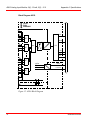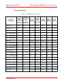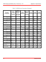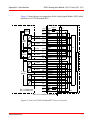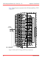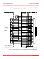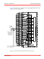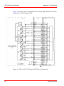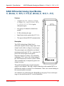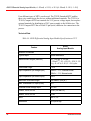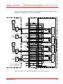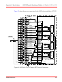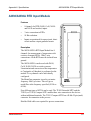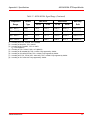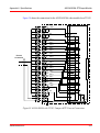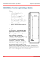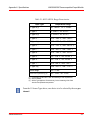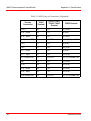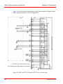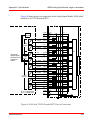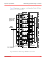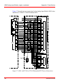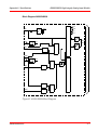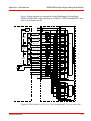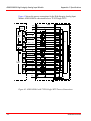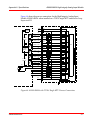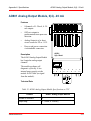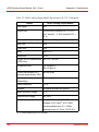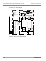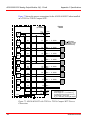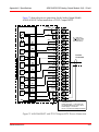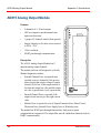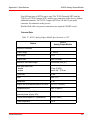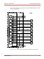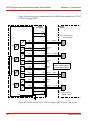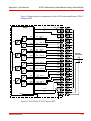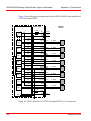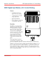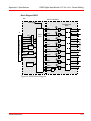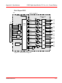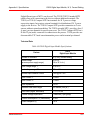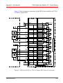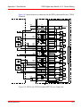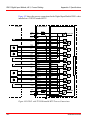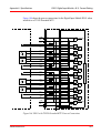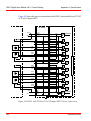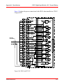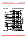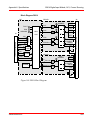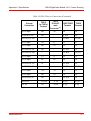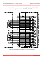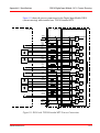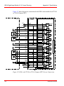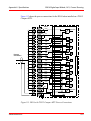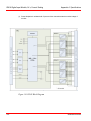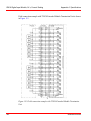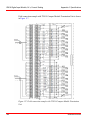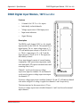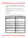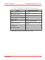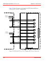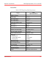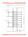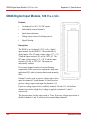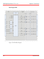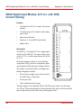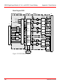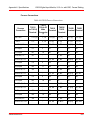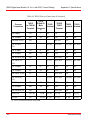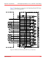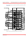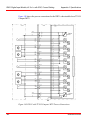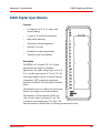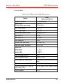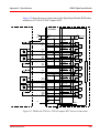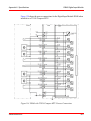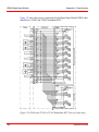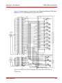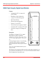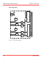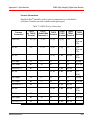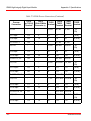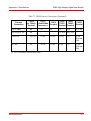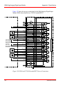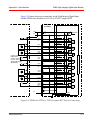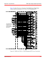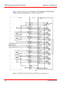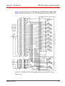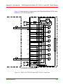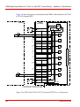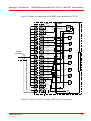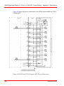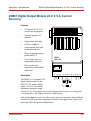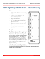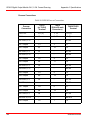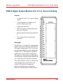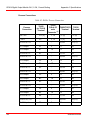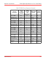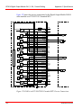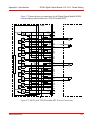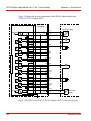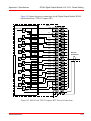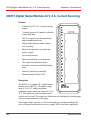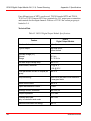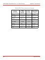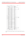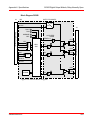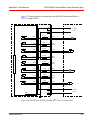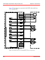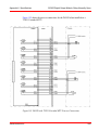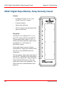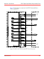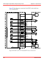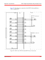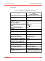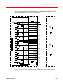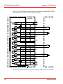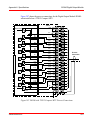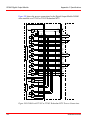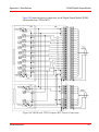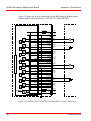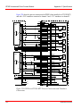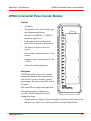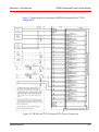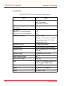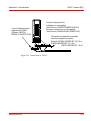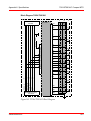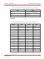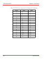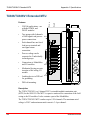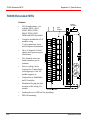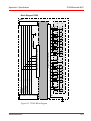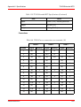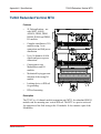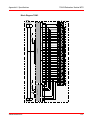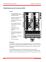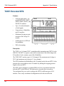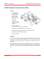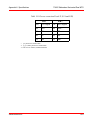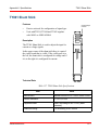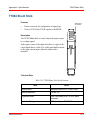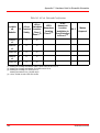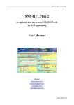
1
S800 I/O Modules and Termination Units Power and productivity for a better world TM S800 I/O Modules and Termination Units NOTICE This document contains information about one or more ABB products and may include a description of or a reference to one or more standards that may be generally relevant to the ABB products. The presence of any such description of a standard or reference to a standard is not a representation that all of the ABB products referenced in this document support all of the features of the described or referenced standard. In order to determine the specific features supported by a particular ABB product, the reader should consult the product specifications for the particular ABB product. ABB may have one or more patents or pending patent applications protecting the intellectual property in the ABB products described in this document. The information in this document is subject to change without notice and should not be construed as a commitment by ABB. ABB assumes no responsibility for any errors that may appear in this document. In no event shall ABB be liable for direct, indirect, special, incidental or consequential damages of any nature or kind arising from the use of this document, nor shall ABB be liable for incidental or consequential damages arising from use of any software or hardware described in this document. This document and parts thereof must not be reproduced or copied without written permission from ABB, and the contents thereof must not be imparted to a third party nor used for any unauthorized purpose. The software or hardware described in this document is furnished under a license and may be used, copied, or disclosed only in accordance with the terms of such license. This product meets the requirements specified in EMC Directive 2004/108/EC and in Low Voltage Directive 2006/95/EC. TRADEMARKS All rights to copyrights, registered trademarks, and trademarks reside with their respective owners. Copyright © 2003-2014 by ABB. All rights reserved. Release: Document number: August 2014 3BSE020924-600 Table of Contents About This User Manual General ............................................................................................................................11 User Manual Conventions ...............................................................................................11 Feature Pack .........................................................................................................11 Warning, Caution, Information, and Tip Icons ....................................................12 Terminology.....................................................................................................................13 Related Documentation ...................................................................................................14 Released User Manuals and Release Notes.....................................................................15 Section 1 - Introduction Product Overview ............................................................................................................18 Module Termination Units and Terminal Units ...................................................18 S800 I/O Modules ................................................................................................29 S800L I/O Modules..............................................................................................38 Prerequisites and Requirements ......................................................................................41 Section 2 - Configuration Module Termination Units (MTU) ..................................................................................43 I/O Modules.....................................................................................................................46 S800 I/O Modules ................................................................................................46 S800L I/O Modules..............................................................................................46 Section 3 - Maintenance Preventive Maintenance ..................................................................................................47 Hardware Indicators ........................................................................................................47 S800 I/O Module LEDs .......................................................................................47 3BSE020924-600 5 Table of Contents S800L I/O Module LED ...................................................................................... 51 Error Messages................................................................................................................ 53 Fault Finding and User Repair ........................................................................................ 53 S800 I/O Module Replacement............................................................................ 53 S800L I/O Module Replacement ......................................................................... 57 Appendix A - Specifications General S800 I/O Specifications ..................................................................................... 61 Features ............................................................................................................ 61 Description........................................................................................................... 61 Technical Data ..................................................................................................... 63 AI801 Analog Input Module, 0(4)...20 mA .................................................................... 64 AI810 Analog Input Module, 0(4)...20 mA, 0(2)...10 V................................................. 70 AI815 Analog Input Module ........................................................................................... 84 AI820 Differential Analog Input Module, +/- 20 mA, +/- 10 V, +/- 5 V (4...20 mA, 2...10 V, 1...5 V) ................................. 97 AI825 Galvanic Isolated Analog Input Module............................................................ 106 AI830/AI830A RTD Input Module............................................................................... 113 AI835/AI835A Thermocouple/mV Input Module ........................................................ 124 AI843 Thermocouple/mV Input Module ...................................................................... 136 AI845 Analog Input Module, single or redundant ........................................................ 148 AI880/AI880A High Integrity Analog Input Module ................................................... 165 AO801 Analog Output Module, 0(4)...20 mA .............................................................. 179 AO810/AO810V2 Analog Output Module, 0(4)...20 mA ............................................ 185 AO815 Analog Output Module..................................................................................... 194 AO820 Galvanically Isolated Bipolar Analog Output Module..................................... 203 AO845/AO845A Analog Output Module, Single or Redundant .................................. 212 DI801 Digital Input Module, 24 V, Current Sinking..................................................... 223 DI802 Digital Input Module, 120 V a.c./d.c, Current Sinking...................................... 228 DI803 Digital Input Module, 230 V a.c./d.c, Current Sinking...................................... 234 DI810 Digital Input Module, 24 V, Current Sinking..................................................... 240 DI811 Digital Input Module, 48 V, Current Sinking..................................................... 254 DI814 Digital Input Module, 24 V, Current Sourcing................................................... 266 6 3BSE020924-600 Table of Contents DI818 Digital Input Module, 24 v, Current Sinking......................................................276 DI820 Digital Input Module, 120 V a.c./d.c..................................................................285 DI821 Digital Input Module, 230 V a.c./d.c..................................................................295 DI825 Digital Input Module, 125 V d.c with SOE........................................................305 DI828 Digital Input Module, 120 V a.c./d.c..................................................................316 DI830 Digital Input Module, 24 V d.c. with SOE, Current Sinking ..................................................................................................324 DI831 Digital Input Module, 48 V d.c. with SOE, Current Sinking ..................................................................................................337 DI840 Digital Input Module ..........................................................................................349 DI880 High Integrity Digital Input Module ..................................................................364 DI885 Digital Input Module, 24 V /48 V d.c. with SOE, Current Sinking ..................................................................................................378 DO801 Digital Output Module 24 V, 0.5 A, Current Sourcing.....................................389 DO802 Digital Output Module, 24-250 V, Relay Normally Open................................394 DO810 Digital Output Module 24 V, 0.5 A Current Sourcing......................................400 DO814 Digital Output Module 24 V, 0.5 A, Current Sinking.......................................409 DO815 Digital Output Module 24 V, 2 A, Current Sourcing........................................420 DO818 Digital Output Module 24 V, 0.5 A, Current Sourcing.....................................430 DO820 Digital Output Module, Relay Normally Open ................................................440 DO821 Digital Output Module, Relay Normally Closed ..............................................450 DO828 Digital Output Module, Relay Normally Open ................................................460 DO840 Digital Output Module......................................................................................467 DO880 High Integrity Digital Output Module ..............................................................478 DP820 Incremental Pulse Counter Module ...................................................................491 DP840 Incremental Pulse Counter Module ...................................................................511 TU805 Terminal Unit ....................................................................................................530 TU810/TU810V1 Compact MTU .................................................................................533 TU811/TU811V1 Compact MTU .................................................................................538 TU812/TU812V1 Compact MTU .................................................................................543 TU813 Compact MTU ..................................................................................................548 TU814/TU814V1 Compact MTU .................................................................................555 TU818 Compact MTU ..................................................................................................562 3BSE020924-600 7 Table of Contents TU819 Compact MTU .................................................................................................. 567 TU830/TU830V1 Extended MTU ................................................................................ 574 TU831/TU831V1 Extended MTU ................................................................................ 582 TU833 Extended MTU ................................................................................................. 587 TU834 Extended MTU ................................................................................................. 593 TU835/TU835V1 Extended MTU ................................................................................ 598 TU836/TU836V1 Extended MTU ................................................................................ 604 TU837/TU837V1 Extended MTU ................................................................................ 610 TU838 Extended MTU ................................................................................................. 616 TU839 Extended MTU ................................................................................................. 622 TU842 Redundant Horizontal MTU ............................................................................. 628 TU843 Redundant Vertical MTU.................................................................................. 633 TU844 Redundant Horizontal MTU ............................................................................. 638 TU845 Redundant Vertical MTU.................................................................................. 643 TU850 Extended MTU ................................................................................................. 648 TU851 Extended MTU ................................................................................................. 654 TU852 Redundant Horizontal Dual MTU .................................................................... 659 TU854 Redundant Horizontal MTU ............................................................................. 665 TY801 Shunt Stick ........................................................................................................ 671 TY804 Shunt Stick ........................................................................................................ 673 TY820 Temperature Sensor .......................................................................................... 675 Appendix B - Certifications Certifications ................................................................................................................. 677 Appendix C - Hardware Units for Essential Automation INDEX 8 3BSE020924-600 Safety Summary Electrostatic Sensitive Device Devices labeled with this symbol require special handling precautions as described in the installation section. GENERAL WARNINGS Equipment Environment All components, whether in transportation, operation or storage, must be in a noncorrosive environment. Electrical Shock Hazard During Maintenance Disconnect power or take precautions to insure that contact with energized parts is avoided when servicing. SPECIFIC CAUTIONS 3BSE020924-600 Page-56: Since the module has normally closed relay contacts the field power must be removed before replacement. It may be necessary to set the process device manually to a safe state before the module is extracted. Turning locking mechanism deactivates the module, that is, relay contacts will close. 9 Safety Summary 10 3BSE020924-600 About This User Manual General Any security measures described in this User Manual, for example, for user access, password security, network security, firewalls, virus protection, etc., represent possible steps that a user of an 800xA System may want to consider based on a risk assessment for a particular application and installation. This risk assessment, as well as the proper implementation, configuration, installation, operation, administration, and maintenance of all relevant security related equipment, software, and procedures, are the responsibility of the user of the 800xA System. This book provides a description of S800 I/O modules and termination units. It provides instructions for site planning and installation, start-up and shutdown procedures, and information regarding capacity and performance. This book is not intended to be the sole source of instruction for the S800 I/O system. User Manual Conventions Microsoft Windows conventions are normally used for the standard presentation of material when entering text, key sequences, prompts, messages, menu items, screen elements, etc. Feature Pack The Feature Pack content (including text, tables, and figures) included in this User Manual is distinguished from the existing content using the following two separators: 3BSE020924-600 11 Warning, Caution, Information, and Tip Icons About This User Manual Feature Pack Functionality______________________________________________________________________ <Feature Pack Content> ___________________________________________________________________________________________ Feature Pack functionality included in an existing table is indicated using a table footnote (*): * Feature Pack Functionality Feature Pack functionality in an existing figure is indicated using callouts. Unless noted, all other information in this User Manual applies to 800xA Systems with or without a Feature Pack installed. Warning, Caution, Information, and Tip Icons This User Manual includes Warning, Caution, and Information where appropriate to point out safety related or other important information. It also includes Tip to point out useful hints to the reader. The corresponding symbols should be interpreted as follows: Electrical warning icon indicates the presence of a hazard that could result in electrical shock. Warning icon indicates the presence of a hazard that could result in personal injury. Caution icon indicates important information or warning related to the concept discussed in the text. It might indicate the presence of a hazard that could result in corruption of software or damage to equipment/property. Information icon alerts the reader to pertinent facts and conditions. Tip icon indicates advice on, for example, how to design your project or how to use a certain function 12 3BSE020924-600 About This User Manual Terminology Although Warning hazards are related to personal injury, and Caution hazards are associated with equipment or property damage, it should be understood that operation of damaged equipment could, under certain operational conditions, result in degraded process performance leading to personal injury or death. Therefore, fully comply with all Warning and Caution notices. Terminology A complete and comprehensive list of terms is included in System 800xA System Guide Functional Description (3BSE038018*). The listing includes terms and definitions that apply to the 800xA System where the usage is different from commonly accepted industry standard definitions and definitions given in standard dictionaries such as Webster’s Dictionary of Computer Terms. Terms that uniquely apply to this instruction may be included here as part of this document. Term Description FCI The Fieldbus Communication Interface (FCI) device contains the interface to the fieldbus (for example PROFIBUS or AF100). G3 compliant The module withstand more severe environmental conditions according to ISA-S71.04. I/O cluster An I/O cluster can have up to 12 I/O devices. I/O device A complete I/O device consists of one MTU and one I/O module. I/O module Is an active, electronic and signal conditioning unit. Can be a part of an I/O device or a S800L I/O module. I/O station An I/O station consists of one or two FCI(s), 1-7 I/O clusters and up to 24 I/O devices. ModuleBus Is an incremental, electrical or optical, bus for interconnection of I/O devices. 3BSE020924-600 13 Related Documentation About This User Manual ModuleBus master ModuleBus master can be a controller (AC 800M) or a FCI. A ModuleBus master contains a ModuleBus interface and power regulators. The FCI module can manage 24 I/O devices and the controller up to 96 I/O modules (up to 12 directly and to the others in 1 to 7 I/O clusters). MTU The Module Termination Unit is a passive base unit containing process terminals and a part of the ModuleBus. OSP Outputs Set as Predetermined. A user configurable action on an output module when communications is lost to the FCI or Controller RTD Resistance Temperature Detector SOE Sequence of events. Time stamping of status changes for digital inputs. TC Thermocouple Related Documentation The following is a listing of documentation related to the S800 I/O system. Table 1. List of Documents Related to S800 I/O system Title S800 I/O Getting Started Description Describes the general installation and configuration information for the S800 I/O system. S800 I/O Modules and Termination Units Describes the modules and termination with Intrinsic Safety Interface units with I.S. interface in the S800 I/O system. S800 I/O Fieldbus Communication Interface for AF100 User’s Guide 14 Describes the AF100 FCI in the S800 I/O system. 3BSE020924-600 About This User Manual Released User Manuals and Release Notes Table 1. List of Documents Related to S800 I/O system (Continued) Title Description S800 I/O Fieldbus Communication Interface for PROFIBUS-DP/DPV1 Describes the PROFIBUS-DP FCI in the S800 I/O system. S800 I/O PROFIBUS_DP Fieldbus Communication Interface Reference Manual Describes the memory mapping on PROFIBUS for the S800 I/O system. Interference-free Electronics Describes the rules for the installation of equipment to ensure the correct operation of equipment in environments where disturbance are present. Released User Manuals and Release Notes A complete list of all User Manuals and Release Notes applicable to System 800xA is provided in System 800xA Released User Manuals and Release Notes (3BUA000263*). System 800xA Released User Manuals and Release Notes (3BUA000263*) is updated each time a document is updated or a new document is released. It is in pdf format and is provided in the following ways: • Included on the documentation media provided with the system and published to ABB SolutionsBank when released as part of a major or minor release, Service Pack, Feature Pack, or System Revision. • Published to ABB SolutionsBank when a User Manual or Release Note is updated in between any of the release cycles listed in the first bullet. A product bulletin is published each time System 800xA Released User Manuals and Release Notes (3BUA000263*) is updated and published to ABB SolutionsBank. 3BSE020924-600 15 Released User Manuals and Release Notes 16 About This User Manual 3BSE020924-600 Section 1 Introduction The S800 I/O is distributed as modular I/O that communicates with numerous controllers over Advant Fieldbus 100 (AF100), PROFIBUS-DP, or directly. The S800 I/O provides easy installation of the I/O modules and process cabling. It is highly modularized and flexible so that I/O modules can be combined to suit many applications. The S800 I/O can be mounted in many configurations to fit most requirements. Figure 1. S800 I/O with Fieldbus Communication Interface CI801 and I/O Modules Mounted on Compact Type of Termination Units. 3BSE020924-600 17 Product Overview Section 1 Introduction Product Overview The S800 I/O provides easy installation of the I/O modules and process cabling. It is highly modularized and flexible so that the I/O modules can be combined to suit many applications, including most types of signals, HART and Intrinsic Safety Interface. The S800 I/O modules and a Fieldbus Communication Interface (FCI) are combined to form an I/O Station. The S800 I/O can be used in both single and redundant applications. In general, all S800 units are G3 compliant. G3 compliant modules withstand more severe environmental conditions according to ISA-S71.04. The following S800 units are G2 compliant - SD821, SD822, SD823, SD831, SD832, SD833, SD834, SS822, SS832, TB811 and CI830. G3 compliant versions of SD822 and SS822 are also available (refer to SD822Z and SS822Z). All modules are marked with a bar code that shows the serial number, article ID and the product revision number. A separate bar code strip is also enclosed along with the module for placing on the module, if needed. The bar code is of type Bar-code 128. For more information, refer to S800 I/O Getting Started(3BSE020923*) manual. The S800 I/O can be categorized into: • Module Termination Units (MTU) • I/O modules – S800 I/O modules and S800L I/O modules. S800 I/O modules are designed to be used together with a Module Termination Unit. S800L I/O modules are designed to be directly mounted on a standard DIN rail. The module also contains terminals for connections. Module Termination Units and Terminal Units The Module Termination Units (MTU) are passive base units used to house the I/O modules. They contain the process wiring terminals and a section of the ModuleBus. The Module Termination Units (MTU) distributes the ModuleBus to the I/O module and to the next MTU. It also generates the correct address to the I/O module by shifting the outgoing position signals to the next MTU. 18 3BSE020924-600 Section 1 Introduction Module Termination Units and Terminal Units Two mechanical keys are used to configure the MTU for different types of I/O modules. This is only a mechanical configuration and it does not affect the functionality of the MTU or the I/O module. Each key has six positions, which gives a total number of 36 different configurations. The configuration can be changed with a screwdriver. The MTU can be mounted on a standard DIN rail. It has a mechanical latch that locks the MTU to the DIN rail. The latch can be released with a screwdriver. The MTU has a mechanical locking mechanism that locks the module in its position. This mechanism also gives the signal BLOCK to the I/O module that keeps the module in its init state until it is locked in its position. The top part of the MTU can be removed to replace the termination board even with the system running. Such a need can be caused by a damaged terminal screw. The MTUs are available in tree versions (Compact, Extended and Redundant). The Compact MTU version typically provides for a compact installation of the I/O modules using 1 wire connections. The Extended MTU version provides for a more complete installation on the MTU, including 3 wire connection, fuses and field circuit power distribution. See Figure 3 and Figure 4 for an illustration of the MTUs together with the I/O modules. The Redundant MTUs are used in redundant I/O applications. There is space on the MTU for two I/O modules on separate ModuleBuses. See Figure 5. 3BSE020924-600 19 Module Termination Units and Terminal Units Section 1 Introduction The Terminal Unit is a passive unit that enables 2- and 3-wire connections of process signals. The Terminal Unit is mounted direct on an S800L I/O module. See Figure 2, S800L I/O module with terminal unit TU805. 58.5 Figure 2. S800L Module with TU805 20 3BSE020924-600 Section 1 Introduction Module Termination Units and Terminal Units See Table 2 for information about the combination between MTU and I/O modules and to specifications in Appendix A, Specifications for more information. 127 mm 7 mm (.27”) (4.8”) 67.5 mm (2.66”) FE A D FE 99.5 mm (3.92”) A B C D 1 2 3 4 5 6 7 8 9 10 11 12 13 14 15 16 B C 162 mm (6.37”) F R W DI810 24V 7 mm (.27”) 58.5 mm (2.3”) 40 mm (1.57”) 5 mm (0.2”) 31.5 mm (1.24") Figure 3. Typical Compact MTU with I/O Module 3BSE020924-600 21 Module Termination Units and Terminal Units Section 1 Introduction 67.5 mm (2.66”) (1.85”) DI810 24V 46.5 mm A A 1 2 3 4 5 6 7 8 9 10 11 12 13 14 15 16 FE F R W FE 109 mm (4.3”) B C D D 7 mm (.27”) B C 5 mm (0.2”) 45 mm (1.77”) 127 mm (4.8”) 7 mm (.27”) 31.5 mm (1.24") 120.5 mm (4.74”) 80 mm (3.15”) Figure 4. Typical Extended MTU with I/O Module 22 3BSE020924-600 Section 1 Introduction Module Termination Units and Terminal Units 126 Figure 5. Typical Redundant MTU with I/O Module TU805 Terminal Unit for 50 Volt Applications The TU805 is a 16 channel terminal unit. Used to enable 2- and 3-wire connections on DI801 or DO801. The Terminal Unit is mounted direct on DI801 or DO801. TU810/TU810V1 Compact MTU for 50 Volt Applications The TU810 is a 16 channel compact module termination unit. The TU810 has three rows of terminals for field signals and process power connections. 3BSE020924-600 23 Module Termination Units and Terminal Units Section 1 Introduction TU811/TU811V1 Compact MTU for 250 Volt Applications The TU811 is a 8 channel compact module termination unit. The TU811 has three rows of terminals for field signals and process power connection. TU812/TU812V1 Compact MTU for 50 Volt Applications and 25 pin D-sub for Process Connections The TU812 is a 16 channel compact module termination unit. The TU812 has a 25 pin D-Sub connector for field signals and process power connections. TU813 Compact MTU for 250 V Applications The TU813 is a 8 channel compact module termination unit. The TU813 has three rows of crimp snap-in connectors for field signals and process power connections. TU814/TU814V1 Compact MTU for 50 Volt Applications The TU814 is a 16 channel compact module termination unit. The TU814 has three rows of crimp snap-in connectors for field signals and process power connections. TU818 Compact MTU for 50 Volt Applications The TU818 is a 32 channel compact module termination unit. It consists of 40 pole screw-terminals for process connections. TU819 Compact MTU for 50 Volt Applications The TU819 is a 32 channel compact module termination unit. It consists of two D-sub 25 pole connector for field signals and process power connections, which enables connection to the Phoenix Varioface, ABB interfast and so on. TU830/TU830V1 Extended MTU for 50 Volt Applications The TU830 is a 16 channel extended module termination unit. The TU830 has three rows of terminals for field signals and process power connection. 24 3BSE020924-600 Section 1 Introduction Module Termination Units and Terminal Units TU831/TU831V1 Extended MTU for 250 Volt Applications The TU831 is a 8 channel extended module termination unit. TU831 has two rows of terminals for field signals and process power connection. TU833 Extended MTU for 50 Volt Applications The TU833 is a 16 channel extended module termination unit. The TU833 has three rows of spring-case terminals for field signals and process power connection. TU834 Extended MTU for 50 Volt Applications The TU834 is a 8 channel extended module termination unit. The MTU has two rows of terminals for field signals and process power connection. The MTU has place for 8 replaceable shunt sticks (i.e one shunt stick per channel) for conversion of the input current signal to a voltage signal. TU835/TU835V1 Extended MTU, Individually Fused per Channel for 50 Volt Applications The TU835 is a 8 channel extended module termination unit. The TU835 has two rows of terminals for process power connection and a single row of field signal connections. Each channel has one fused (3 A max.) transmitter power outlet terminal and one signal terminal. Process voltage can be connected to 2 individually isolated groups. TU836/TU836V1 Extended MTU, Individually Fused per Channel for 250 Volt Applications The TU836 is a 8 channel extended module termination unit. The TU836 has two rows of terminals for field signals and process power connection. Each channel has one fused (3 A max.) power outlet terminal and one signal return terminal. Process voltage can be connected to 2 individually isolated groups. The standard fuse holder that comes with the TU836 can be changed to an indicating fuse holder. This indicating fuse holder can be ordered from Phoenix Contact: 15-30 VDC type, order 3118119 110-250 VAC type, order 3118106. 3BSE020924-600 25 Module Termination Units and Terminal Units Standard fuse holder Section 1 Introduction Optional fuse holder with fuse status indication for 15-30 VDC or 110-250 VAC Figure 6. Exchange of Standard Fuse Holder for Indication Type TU837/TU837V1 Extended MTU, Individually Fused per Channel for 250 Volt Applications The TU837 is a 8 channel extended module termination unit. The TU837 has two rows of terminals for field signals and process power connection. Each channel has one fused (3 A max.) power outlet terminal and two signal terminals. Process voltage return can be connected to two individually isolated groups. TU838 Extended MTU, Individually Fused per Channel for 50 Volt Applications The TU838 is a 16 channel extended module termination unit. The TU838 has two rows of terminals for field signals and process power connection. Each channel has one fused (3 A max.) transmitter power outlet terminal and one signal terminal. Process voltage can be connected to two individually isolated groups. TU839 Extended MTU for 250 Volt Applications The TU839 is a 8 channel extended module termination unit. TU839 has two rows of terminals for field signals and process power connection. Each channel has one sensor power outlet terminal and two signal terminals. Process voltage can be connected to two individually isolated groups. 26 3BSE020924-600 Section 1 Introduction Module Termination Units and Terminal Units TU842 Redundant Horizontal MTU for 50 V Applications The TU842 is a 16 channel redundant module termination unit. The TU842 has three rows of terminals for field signals and process power connection.It is intended for mounting on a horizontal DIN rail. There is space on the MTU for two I/O modules connected to separate ModuleBuses. TU843 Redundant Vertical MTU for 50 V Applications The TU843 is a 16 channel redundant module termination unit. The TU843 has three rows of terminals for field signals and process power connection. It is intended for mounting on a vertical DIN rail. There is space on the MTU for two I/O modules connected to separate ModuleBuses. TU844 Redundant Horizontal MTU for 50 V Applications The TU844 is a 8 channel redundant module termination unit. The TU844 has two rows of terminals for field signals and process power connection. It is a intended for mounting on a horizontal DIN rail. The MTU has place for 8 replaceable shunt sticks (i.e one shunt stick per channel) for conversion of the input current signal to a voltage signal. There is space on the MTU for two I/O modules connected to separate ModuleBuses. TU845 Redundant Vertical MTU for 50 V Applications The TU845 is a 8 channel redundant module termination unit. The TU845 has three rows of terminals for field signals and process power connection. It is intended for mounting on a vertical DIN rail. The MTU has place for 8 replaceable shunt sticks (i.e one shunt stick per channel) for conversion of the input current signal to a voltage signal. There is space on the MTU for two I/O modules connected to separate ModuleBuses. TU850 Extended MTU, Individually Current Limited and Disconnectable per Channel for 50 V Applications The TU850 is a 16 channel extended module termination unit. TU850 has two rows of terminals for field signals and process power connection. Each channel has one current limited sensor/transmitter power outlet terminal and one signal terminal. Process voltage can be connected to two individually isolated groups. 3BSE020924-600 27 Module Termination Units and Terminal Units Section 1 Introduction TU851 Extended MTU for 250 Volt Applications The TU851 250V Extended MTU Which allows a maximum of 16 isolated I/O channels and process voltage connections. It has a 32 pole screw-terminal for process connections. TU852 Redundant Horizontal MTU for 50 V Applications The TU852 is a redundant module termination unit for up to 16 channels. The TU852 has a two 25 pin D-Sub connector for field signals and process power connections. It is a intended for mounting on a horizontal DIN rail. There is space on the MTU for two I/O modules connected to separate Modulebuses. TU854 Redundant Horizontal MTU for 50 V Applications he TU854 is a 8 channel redundant module termination unit. The TU854 has a 25 pin D-Sub connector for field signals and process power connections. It is a intended for mounting on a horizontal DIN rail. The MTU has place for 8 replaceable shunt sticks (i.e one shunt stick per channel) for conversion of the input current signal to a voltage signal. There is space on the MTU for two I/O modules connected to separate ModuleBuses. TY801 Shunt Stick The TY801 is a shunt stick for current or voltage signals together with AI845 or AI880 and TU844 or TU845. TY804 Shunt Stick The TY804 is a shunt stick for NAMUR signals together with DP840 and TU844 or TU845. TY820 Temperature Sensor The TY820 can be used with AI835/AI835A and AI843 to measure cold junction temperature. 28 3BSE020924-600 Section 1 Introduction S800 I/O Modules S800 I/O Modules The I/O modules have open ventilated plastic enclosures. On the front of all I/O modules there are at least three LEDs (FAULT, RUN and WARNING) indicating the module status. Additionally some modules have LEDs indicating OSP or PRIMARY, see Table 3 and Table 4. I/O modules may be replaced in a fully operational I/O station. Mechanical keying on modules and MTUs protect I/O modules from being inserted in positions where they could be damaged by excessive voltage or current. An electronic type designation ID in each module keeps the I/O module from being taken into operation by the ModuleBus master, if a module’s ID doesn’t match the configured module type definition. There are modules for both single and redundant applications. Refer to specifications in Appendix A, Specifications for more information. AI810 Analog Input Module, 0...20 mA, 0...10 V The AI810 Analog Input Module has 8 current and voltage inputs. The inputs are independent for each channel, in that either voltage or current can be measured. The current input is able to handle a short circuit to the transmitter supply without damage. The input withstand HART communication. Nominal input ranges are: 0(4)... +20 mA, 0(2)... +10 V. AI815 Analog Input Module, 0..20mA, 0..5V, HART The AI815 Analog Input Module has 8 analog inputs. The inputs can be configured for voltage or current. The module has HART pass-through functionality. Nominal input ranges are: 0(4)...+20 mA, 0(1)...+5 V. AI820 Differential Analog Input Module, +/- 20 mA, +/- 10 V, +/- 5 V The AI820 Differential Analog Input Module has 4 differential, bipolar current/voltage inputs. This module is suitable for applications requiring high common mode rejection ratings, and/or bipolar voltage or current inputs. Nominal 3BSE020924-600 29 S800 I/O Modules Section 1 Introduction input ranges are: -20...+20 mA, 0(4)...+20 mA, -10...+10 V, 0(2)...+10 V, -5...+5 V and 0(1)...+5 V. The current input is able to handle a short circuit to the transmitter supply without damage. The input withstand HART communication. AI825 Galvanic Isolated Analog Input Module, -20...+20 mA, 0(4)...+20 mA, 10...+10 V, 0(2)...+10 V The AI825 Galvanic Isolated Analog Input Module has 4 individually galvanic isolated channels. This module is suitable for applications requiring galvanic isolated channels, and/or bipolar voltage or current inputs. Nominal input ranges are: -20...+20 mA, 0(4)...+20 mA, -10...+10 V, 0(2)...+10 V. The current input is able to handle a short circuit to the transmitter supply without damage. The input withstand HART communication. AI830/AI830A RTD Input Module The AI830/AI830A Analog Input, RTD Module has 8 RTD (Pt100, Cu10, Ni100 and Ni120 and resistor) inputs. The inputs allow 3-wire connection to RTDs. Inputs are monitored for open-circuit, short-circuit. Reference channel and internal supply are also monitored. AI835/AI835A Thermocouple/mV Input Module The AI835/AI835A Analog Input, Thermocouple/mV Module has 8 differential inputs for TC/mV measurements. One channel (channel 8) can be configured for “Cold Junction” (ambient) temperature measurement, thus serving as the CJchannel for the other channels on the module. All 8 channels can be used if no CJtemperature measurement is needed. The inputs can be connected to a variety of thermocouples with the following characteristics: B, C, E, J, K, N, R, S and T also D, L and U for AI835A. AI843 Thermocouple/mV Input Module, for Single or Redundant Applications The AI843 Analog Input, Thermocouple/mV Module has 8 differential inputs for TC/mV measurements. A separate channel is used for Cold Junction (ambient) 30 3BSE020924-600 Section 1 Introduction S800 I/O Modules temperature measurement. The input can be connected to a variety of thermocouples with the following characteristics: B, C, E, J, K, L, N, R, S, T and U. AI845 Analog Input Module, for Single or Redundant Applications The AI845 Analog Input Module has 8 analog inputs. Each channel can be either a voltage or current input. The module has advanced on-board diagnostics and HART pass-through functionality. It can be used in both single and redundant application. Nominal input ranges are: 0(4)...+20mA, 0(1)...+5V. AI880/AI880A High Integrity Analog Input Module for Single or Redundant Configuration The AI880/AI880A High Integrity Analog Input Module is TÜV certified for IEC 61508 SIL3, and EN 954-1 Category 4. The AI880/AI880A has 8 analog inputs. The channels are for current input. The module has advanced on-board diagnostics. It can be used in both single and redundant configuration. The AI880/AI880A complies with the NAMUR recommendation NE43, and supports configurable over- and under range limits. AI880A has support for HART pass-through communication. Nominal input range is 0(4)...+20mA. A0810/AO810V2 Analog Output Module, 0...20 mA The AO810/AO810V2 Analog Output Module has 8 current outputs. State of outputs can be set to a predetermined (OSP) value if a communication error is detected. Nominal output range is: 0(4)... 20 mA. AO815 Analog Output Module, 4...20 mA, HART The AO815 Analog Output Module has 8 analog outputs. State of outputs can be set to a predetermined (OSP) value if a communication error is detected. The module has HART pass-through functionality. Nominal output range is 4...20 mA. 3BSE020924-600 31 S800 I/O Modules Section 1 Introduction AO820 Bipolar Analog Output Module, -20 mA...+20 mA, -10 V...+10 V The AO820 Bipolar Analog Output Module has 4 bipolar current or voltage outputs. The choice of either current or voltage output is configurable per channel. Outputs are individually galvanically isolated. State of outputs can be set to a predetermined (OSP) value if a communication error is detected. Nominal output range are: -20... +20 mA, 0(4)... +20 mA, -10... +10 V, 0(2)... +10 V. AO845/AO845A Analog Output Module, for Single or Redundant Applications The AO845/AO845A Analog Output Module has 8 analog outputs. State of outputs can be set to a predetermined (OSP) value if a communication error is detected. The module has advanced on-board diagnostics and HART pass-through functionality. It can be used in both single and redundant applications. Nominal output range is: 4...20mA. DI810 Digital Input Module, 24 V, Current Sinking The DI810 Digital Input Module has 16 channels for 24 volt d.c. digital inputs. The inputs are divided into two isolated groups of eight channels with a voltage supervision input for each group. Each input channel provides current limiting, EMC protection, input state LED indicator and optical isolation from the ModuleBus. DI811 Digital Input Module, 48 V, Current Sinking The DI811 Digital Input Module has 16 channels for 48 volt d.c. digital inputs. The inputs are divided into two isolated groups of eight channels with a voltage supervision input for each group. Each input channel provides current limiting, EMC protection, input state LED indicator and optical isolation from the ModuleBus. DI814 Digital Input Module, 24 V, Current Sourcing The DI814 Digital Input Module has 16 channels for 24 volt d.c. current source digital inputs. The inputs are divided into two isolated groups of eight channels with a voltage supervision input for each group. Each input channel provides current limiting, EMC protection, input state LED indicator and optical isolation from the ModuleBus. 32 3BSE020924-600 Section 1 Introduction S800 I/O Modules DI818 Digital Input Module, 24 V, Current Sinking The DI818 Digital Input Module has 32 channels for 24 volt d.c. digital inputs. The inputs are divided into two isolated groups of 16 channels with a voltage supervision input for each group. Each input channel provides current limiting, EMC protection, input state LED indicator and optical isolation from the ModuleBus. DI820 Digital Input Module, 120 V a.c./d.c. The DI820 Digital Input Module has 8 channels for 120 volt a.c./d.c. digital inputs. The inputs are individually isolated. Channel 1 can be used as voltage supervisor for channels 2 - 4, and channel 8 can be used for channels 5 - 7. If voltage supervision is disabled, channels 1 and 8 can be used as normal inputs. Each input channel provides current limiting, EMC protection, input state LED indicator, noise filter and optical isolation from the ModuleBus. DI821 Digital Input Module, 230 V a.c./d.c. The DI821 Digital Input Module has 8 channels for 230 volt a.c./d.c. digital inputs. The inputs are individually isolated. Channel 1 can be used as voltage supervisor for channels 2 - 4, and channel 8 can be used for channels 5 - 7. If voltage supervision is disabled, channels 1 and 8 can be used as normal inputs. Each input channel provides current limiting, EMC protection, input state LED indicator, noise filter and optical isolation from the ModuleBus. DI825 Digital Input Module, 125 V d.c. with SOE The DI825 Digital Input Module had 8 channels for 125 V d.c. digital inputs and sequence of events (SOE) handling capabilities. The sequence of events time stamp has a resolution of 0.4 ms for each input channel. The inputs are individually isolated. Channel 1 can be used as voltage supervisor for channels 2 - 4, and channel 8 can be used for channels 5 - 7. If voltage supervision is disabled, channels 1 and 8 can be used as normal inputs. Each input channel provides current limiting, EMC protection, input state LED indicator, noise filter and optical isolation from the ModuleBus. 3BSE020924-600 33 S800 I/O Modules Section 1 Introduction DI828 Digital Input Module, 120 V a.c \ d.c The DI828 Digital Input Module has 16 channels for 120 volt a.c./d.c. digital inputs. The inputs are individually isolated. Channel 1 can be used as voltage supervisor for channels 2 - 8, and channel 16 can be used for channels 9 - 15. If voltage supervision is disabled, channels 1 and 16 can be used as normal inputs. Each input channel provides current limiting, EMC protection, input state LED indicator, noise filter and optical isolation from the ModuleBus. DI830 Digital Input Module, 24 V d.c. with SOE, Current Sinking The DI830 Digital Input Module has 16 channels for 24 volt d.c. digital inputs and sequence of events (SOE) handling capabilities. The sequence of events time stamp has a resolution of 0.4 ms for each input channel. The inputs are divided into two isolated groups of eight channels with a voltage supervision input for each group. Each input channel provides current limiting, EMC protection, input state LED indicator and optical isolation from the ModuleBus. DI831 Digital Input Module, 48 V d.c. with SOE, Current Sinking The DI831 Digital Input Module has 16 channels for 48 volt d.c. digital inputs and sequence of events (SOE) handling capabilities. The sequence of events time stamp has a resolution of 0.4 ms for each input channel. The inputs are divided into two isolated groups of eight channels with a voltage supervision input for each group. Each input channel provides current limiting, EMC protection, input state LED indicator and optical isolation from the ModuleBus. DI840 Digital Input Module, for Single or Redundant Applications The DI840 Digital Input Module has 16 channels for 24 V d.c. digital inputs and sequence of events (SOE) handling capabilities. The sequence of events time stamp has a resolution of 1 ms for each input channel. Each input channel provides current limiting, EMC protection, input state LED indicator and optical isolation from the ModuleBus. The module has advanced on-board diagnostics. It can be used in both single and redundant applications. 34 3BSE020924-600 Section 1 Introduction S800 I/O Modules DI880 High Integrity Digital Input Module, for Single or Redundant Configuration The DI880 High Integrity Digital Input Module is TÜV certified for IEC 61508 SIL3 and EN 954-1 Category 4. The DI880 has 16 channels for 24 V d.c. digital inputs and sequence of events (SOE) handling capabilities. The sequence of events time stamp has a resolution of 1 ms for each input channel. Each input channel provides current limiting, EMC protection, input state LED indicator and optical isolation from the ModuleBus.The input voltage range is 18 to 30 V d.c. and the input current is 7 mA at 24 V d.c. The module has advanced on-board diagnostics. It can be used in both single and redundant configuration. DI885 Digital Input Module, 24 V/48 V d.c. with SOE, Current Sinking The DI885 Digital Input Module has 8 channels for 48 volt d.c. digital inputs with or without open-circuit monitoring (wire break supervision), or 24 volt d.c. electronic inputs without open-circuit monitoring; and sequence of events (SOE) handling capabilities. The sequence of events time stamp has a resolution of 1 ms for each input channel. The inputs are arranged in one group of 8 channels. Each input channel provides current limiting, EMC protection, input state LED indicator and optical isolation from the ModuleBus. The DI885 also has the capability to monitor an internal or external sensor power supply (60 V d.c. max.). DO810 Digital Output Module, 24 V, 0.5 A, Current Sourcing The DO810 Digital Output Module has 16 channels for 24 volt d.c., 0.5 A, digital outputs. The outputs are divided into two isolated groups of eight channels with a voltage supervision input for each group. Each output channel provides protection against short circuits to ground, over-voltage, over-temperature, EMC protection, output state LED indicator and optical isolation from the ModuleBus. State of outputs can be set to a predetermined (OSP) value if a communications lost error is detected. 3BSE020924-600 35 S800 I/O Modules Section 1 Introduction DO814 Digital Output Module, 24 V, 0.5 A The DO814 Digital Output Module has 16 channels for 24 volt d.c., 0.5 A, current sinking digital outputs. The outputs are divided into two isolated groups of eight channels with a voltage supervision input for each group. Each output channel provides protection against short circuits to power supply, over-temperature, EMC protection, output state LED indicator and optical isolation from the ModuleBus. State of outputs can be set to a predetermined (OSP) value if a communications lost error is detected. DO815 Digital Output Module, 24 V, 2 A, Current Sourcing The DO815 Digital Output Module has 8 channels, 24 volt d.c., 2 A, digital outputs. The outputs are divided into two isolated groups of four channels with a voltage supervision input for each group. Each output channel provides protection against short circuits to ground, over-temperature, EMC protection, output state LED indicator and optical isolation from the ModuleBus. State of outputs can be set to a predetermined (OSP) value if a communications lost error is detected. DO818 Digital Output Module, 24 V, 0.5 A, Current Sourcing The DO818 Digital Output Module has 32 channels for 24 volt d.c., 0.5 A, digital outputs. The outputs are divided into two isolated groups of 16 channels with a voltage supervision input for each group. Each output channel provides protection against short circuits to ground, over-voltage, over-temperature, EMC protection, output state LED indicator and optical isolation from the ModuleBus. State of outputs can be set to a predetermined (OSP) value if a communications lost error is detected. DO820 Digital Output Module, Relay Normally Open The DO820 Digital Output Module has 8 channels for 230 volt a.c./d.c. relay outputs. The outputs are individually isolated. Each output channel provides a relay contact (NO - Normal Open), EMC protection, output state LED indicator and optical isolation from the ModuleBus. State of outputs can be set to a predetermined (OSP) value if a communications lost error is detected. Internal voltage is supervised. 36 3BSE020924-600 Section 1 Introduction S800 I/O Modules DO821 Digital Output Module, Relay Normally Closed The DO821 Digital Output Module has 8 channels for 230 volt a.c./d.c. relay outputs. The outputs are individually isolated. Each output channel provides a relay contact (NC - Normal Closed), EMC protection, output state LED indicator and optical isolation from the ModuleBus. State of outputs can be set to a predetermined (OSP) value if a communications lost error is detected. Internal voltage is supervised. DO828 Digital Output Module, Relay Normally Open The DO828 Digital Output Module has 16 channels for 250 AC / 125V DC relay outputs. The outputs are individually isolated. Each output channel provides a relay contact (NO - Normal Open), EMC protection, output state LED indicator and optical isolation from the ModuleBus. State of outputs can be set to a predetermined (OSP) value if a communications lost error is detected. Internal voltage is supervised. DO840 Digital Output Module, for Single or Redundant Applications The DO840 Digital Output Module has 16 channels for 24 V d.c. The maximum continuos output current is 0.5 A. The module has advanced on-board diagnostics. It can be used in both single and redundant applications. DO880 High Integrity Digital Output Module, for Single or Redundant Configuration The DO880 High Integrity Digital Output Module is TÜV certified for IEC 61508 SIL3 and EN 954-1 Category 4. The DO880 has 16 channels for 24 V d.c. The maximum continuous output current is 0.5 A. The module has advanced on-board diagnostics. It can be used in both single and redundant configuration. 3BSE020924-600 37 S800L I/O Modules Section 1 Introduction DP820 Incremental Pulse Counter Module DP820 is an two-channel pulse counting module for incremental pulse transmitters up to 1.5 MHz. Each channel contains counters and registers for position/length and speed/frequency measurement. Each channel provides three balanced inputs for connection of a pulse transmitter, one digital input and one digital output. Pulse transmitters with RS422, +5 V, +12 V, +24 V and 13 mA interfaces can be connected to DP820. DP840 Incremental Pulse Counter Module, for Single or Redundant Applications DP840 has 8 channels and each channel can be configured for pulse count or frequency measurement. The maximum frequency of input signals is 20 kHz. The inputs can also be read as digital input signals. Input signal range NAMUR, 12 V and 24 V. S800L I/O Modules The I/O modules have open ventilated plastic enclosures and a bottom of sheet metal. On the front of each I/O module there is one LED (STATUS) indicating the module status and digital I/O modules have one status LED for each channel. Refer to Hardware Indicators on page 47 for the status indication of the LEDs. An electronic type designation ID in each module keeps the I/O module from being taken into operation by the ModuleBus master, if a module’s ID doesn’t match the configured module type definition. Refer to specifications in Appendix A, Specifications for more information. The module can be mounted on a standard DIN rail. The module is locked to the DIN rail by using the locking screw. The process connection is done via detachable connectors. 38 3BSE020924-600 Section 1 Introduction S800L I/O Modules The I/O module distributes the ModuleBus to the next module. It also generate the correct address to the next module by shifting the outgoing position signals. 58.45 mm (2.3”) 67.5 mm (2.66”) Center of DIN rail 110 mm (4.3”) 86.1 mm (3.4”) 136 mm (5.35”) DO801 46.5 mm (1.83”) 5 mm (0.2”) 57.2 mm (2.25”) Figure 7. Dimensions for S800L Modules AI801 Analog Input Module, 0...20 mA The AI801 Analog Input Module has 8 current inputs. The current input is able to handle a short circuit to the transmitter supply without damage. The input withstands HART communication. Nominal input ranges are: 0(4)... +20 mA. AO801 Analog Output Module, 0...20 mA The AO801 Analog Output Module has 8 current outputs. State of outputs can be set to a predetermined (OSP) value if a communications error is detected. Nominal output range is: 0(4)... 20 mA. 3BSE020924-600 39 S800L I/O Modules Section 1 Introduction DI801 Digital Input Module, 24 V, Current Sinking The DI801 Digital Input Module has 16 channels for 24 volt d.c. digital inputs. One input channel can be used for sensor voltage supervision. Each input channel provides current limiting, EMC protection, input state LED indicator and optical isolation from the ModuleBus. DI802 Digital Input Module, 120 V a.c./d.c., Current Sinking The DI802 Digital Input Module has 8 channels for 120 volt a.c./d.c. digital inputs. Channel 8 can be used for sensor voltage supervision. Each input channel provides current limiting, EMC protection, input state LED indicator and optical isolation from the ModuleBus. DI803 Digital Input Module, 230 V a.c./d.c., Current Sinking The DI803 Digital Input Module has 8 channels for 230 volt a.c./d.c. digital inputs. Channel 8 can be used for sensor voltage supervision. Each input channel provides current limiting, EMC protection, input state LED indicator and optical isolation from the ModuleBus. DO801 Digital Output Module, 24 V, 0.5 V, Current Sinking The DO801 Digital Output Module has 16 channels for 24 volt d.c., 0.5 A, digital outputs. Each output channel provides protection against short circuits to ground, over-voltage, over-temperature, EMC protection, output state LED indicator and optical isolation from the ModuleBus. State of outputs can be set to a predetermined (OSP) value if a communications lost error is detected. DO802 Digital Output Module, 24-250 V, Relay Normally Open The DO802 Digital Output Module has 8 channels for 24-250 volt d.c., digital outputs. Each output channel provides protection against short circuits to ground, over-voltage, over-temperature, EMC protection, output state LED indicator and optical isolation from the ModuleBus. State of outputs can be set to a predetermined (OSP) value if a communications lost error is detected. 40 3BSE020924-600 Section 1 Introduction Prerequisites and Requirements Prerequisites and Requirements When the S800 I/O is used with controllers as part of their I/O system, the controllers need to have an interface to the fieldbus network. The fieldbus network connects to a Fieldbus Communications Interface (FCI) with S800 I/O installed. 3BSE020924-600 41 Prerequisites and Requirements 42 Section 1 Introduction 3BSE020924-600 Section 2 Configuration Module Termination Units (MTU) Each MTU is used with certain types of I/O Modules. Refer to Table 2 that shows the relationship between MTUs and I/O Modules. Each MTU has two mechanical keys that have to be set for the type of I/O module that is installed on it. TU839 TU850 Extended TU851 Extended X - - X - X - - - X - A E AI815 X X X - - X - - X - X - - - - - C C AI820 X X - - - X - - - - - - - - - - B B AI825 - - - - X - X - - - - - - - - - D A AI830/ AI830A X - - - X - - - - - - - - - - A F X - - X - - - - - - - - - - B A AI835/ X Redundant TU838 Extended TU844 TU845 TU854 TU836 TU837 - Redundant TU835 Extended - Extended TU831 Extended TU834 Extended X Extended X TU830 TU833 TU819 Compact X Compact TU818 Compact AI810 TU811 TU813 Module Type TU812 TU814 Compact Mech. Key Setting TU810 TU842 TU843 TU852 Table 2. MTU Usage and Key Settings Key Key 1 2 AI835A X AI843 - - X - - X - - - - - - X - - - B A AI845 X X X - - X - - X - X - - X - - C C 3BSE020924-600 X 43 Module Termination Units (MTU) Section 2 Configuration TU850 Extended TU851 Extended - - - - - X - - F F AI880A - - - - - - - X - - - - - X - - F D X - - - X - - - - - - - - - - A E AO810/ Redundant TU839 TU844 TU845 TU854 TU838 Extended - X Redundant TU836 TU837 - Extended TU835 Extended - TU834 Extended - TU831 Extended - Extended - Compact TU819 Compact - TU830 TU833 TU818 Compact AI880 TU811 TU813 Module Type TU812 TU814 Compact Mech. Key Setting TU810 TU842 TU843 TU852 Table 2. MTU Usage and Key Settings (Continued) Key Key 1 2 AO810V2 X AO815 X X - - - X - - - - - - - - - - D B AO820 X X - - - X - - - - - - - - - - B C X - - - X - - - - - - X - - - C C AO845 AO845A X X - - - X - - - - - - X - - - D B DI810 X X X - - X - - - - X - - - X - A A DI811 X X X - - X - - - - X - - - X - B D DI814 X X - - - X - - - - X - - - - - B E DI818 - - X X - X - - - - - - - - - - E A DI820 - - - - X - X - - - - X - - - X A B DI821 - - - - X - X - - - - X - - - X A C DI825 - - - - X - X - - - - X - - - X A B DI828 - - - - - - - - - - - - - - - X E B DI830 X X X - - X - - - - X - - - X - A A DI831 X X X - - X - - - - X - - - X - B D DI840 X X X - - X - - - - X - X - - - C D 44 3BSE020924-600 Section 2 Configuration Module Termination Units (MTU) TU851 Extended X(2) - - - F F - - X - - - - - - - - - - B F - - - X - - - - - - - - - - A A X - - - X - - - - X - - - - - B E X X(3) - - - X - - - - - - - - - - A A DO818 - - X X - X - - - - - - - - - - E A DO820 - - - - X - X - - X - - - - - X A D DO821 - - - - X - X - - X - - - - - X C A DO828 - - - - - - - - - - - - - - - X E D DO840 X X - - - X - - - - - - X - - - C E DO880 X X - - - X - - - - - - X - - - F E DP820 X X - - - X - - - - - - - - - - C B DP840 X X X - - X - - - - - - X X - - C F TU810 DI885 X X X DO810 X X DO814 X DO815 Redundant TU850 Extended TU844 TU845 TU854 TU839 - Redundant TU838 Extended - Extended TU836 TU837 TU842 TU843 TU852 TU835 Extended - Extended - X(1) X(2) - TU830 TU833 - X(1) Compact - DI880 TU811 TU813 X(2) Module Type TU819 Compact - TU818 Compact TU831 Extended Mech. Key Setting TU834 Extended TU812 TU814 Compact Table 2. MTU Usage and Key Settings (Continued) Key Key 1 2 (1) If single Compact MTUs (TU810, TU812 or TU814) are used, refer to the Technical Description 3BSE050455. (2) If the outgoing sensor supplies are not used to feed the sensor in the field, refer to the Technical Description 3BSE050455. (3) TU812 is not recommended due to the maximum rated current. Connecting an MTU to the ModuleBus master, cluster modem or to another MTU, automatically sets up the address selection of that MTU. There are no jumpers or switches that need to be set before installing an I/O module. 3BSE020924-600 45 I/O Modules Section 2 Configuration MTUs are placed on the DIN rails, and then connected to the preceding MTU, ModuleBus master or cluster modem. Once connected, the MTU is locked in place by the bottom latch which also bonds it to the chassis ground. I/O Modules S800 I/O Modules Each I/O module is installed on an MTU. Table 2 shows the MTUs that can be used with each I/O module type. I/O modules do not have any jumpers or switches that need to be set before installing on an MTU. Refer to Appendix A, Specifications for more information. I/O modules are installed by aligning the connectors of the MTU and I/O module and then pushing the units together. After connected to the MTU, the I/O module is then locked in place by the I/O Module Lock/Switch which also activates a switch to enable power to the I/O module. S800L I/O Modules The I/O modules are installed directly on the DIN rail and locked with the locking screw. The process signal are connected to a pluggable connector on the module. There are no jumpers or switches that need to be set. The I/O module automatically set up the address for the next I/O module. To enable 2- and 3-wire connection to 16 channels DI and DO modules, TU805 is used. TU805 is mounted directly on the module. 46 3BSE020924-600 Section 3 Maintenance Preventive Maintenance For preventive maintenance, refer to S800 I/O Getting Started (3BSE020923*) manual. Hardware Indicators S800 I/O Module LEDs Figure 8 shows examples of front panels for different types of I/O modules. On the front of all I/O modules, there are at least three LEDs (FAULT, RUN and WARNING) indicating the module status. Additionally, some modules have LEDs indicating OSP or PRIMARY, see Table 3 and Table 4. Each digital channel has one LED indicating the current state (on/off). 3BSE020924-600 47 S800 I/O Module LEDs Section 3 Maintenance Table 3. Standard LEDs on S800 I/O Modules Marking Color Description F (FAULT) Red Fatal internal module error is detected (Error State) or I/O module is in any of the start-up states (Init State or Not Configured State). (1) R (RUN) Green I/O module is running in Operational State. W (WARNING) Yellow Internal or external channel error is detected, (module continues to run). O (OSP) Yellow I/O module is in OSP (Output Set to Predetermined) State where the outputs are driven to the OSP value. OSP State is entered upon demand from the master (e.g. Profibus) or automatically due to lack of incoming communication. PRIM (PRIMARY) Yellow I/O module is primary within a redundant pair.(2) Channel status Yellow (red) Indicates the current state (on/off). On some modules this LED also indicates channel error (red). (1) The FAULT LED is turned on at power-on and restart. The LED is turned off after the first successful access to the module in Not Configured State. If a module with advanced diagnostics detects a fatal internal error, it enters Error State and turns on the FAULT LED. (2) In a redundant configuration, the primary I/O module is scanned at the specified cycle time to supply input values to the application, while the backup I/O module is scanned at a lower cycle for diagnostic purpose. The input values from the backup module are not used by the application. 48 3BSE020924-600 Section 3 Maintenance S800 I/O Module LEDs Table 4. S800 I/O Module LED Indications in Different States Module state Run Fault Warning OSP Primary Off On Off Off Off DI On/Off (1), DO Off On/Off On/Off Off Off DI On/Off (1), DO Off Flashing/ Off Off On/Off Off Off DI On/Off, DO Off Operational On Off On/Off Off On/Off On/Off OSP On Off On/Off On On/Off On/Off Error Off On On/Off Off Off Init Flashing/ Not Off Configured Ready (2) Channel status DI On/Off, DO Off (1) The DI signal status for module DI830, DI831, DI880, DI885, DP820 is only OFF. (2) Will be switched off after the first successful access to the module. 3BSE020924-600 49 S800 I/O Module LEDs Section 3 Maintenance Normally when an I/O module has been removed from the configuration, the ModuleBus master will do a restart of the module. The module will end up in the NOT CONFIGURED state. F R W O 1 2 3 4 5 6 7 8 9 10 11 12 13 14 15 16 DO810 F R W F R W O F R W F R W O PX1 UP1 ST1 DI1 SY1 DO1 TP1 UL1 PX2 UP2 ST2 DI2 SY2 DO2 TP2 UL2 1 2 3 4 5 6 7 8 9 10 11 12 13 14 15 16 DI810 AO810/AO810V2 AI810 DP820 Figure 8. Examples of S800 I/O Module LED Locations 50 3BSE020924-600 Section 3 Maintenance S800L I/O Module LED S800L I/O Module LED Figure 9 shows examples of front panels for different types of I/O modules. On the front of each I/O module there is one LED indicating the module status. See Table 5 and Table 6 for information on the meaning and indications for these modules. Each digital channel has one LED indicating current state (on/off). Table 5. Standard LED on S800L I/O Modules Marking Color S (Status) Description Red Fatal internal module error is detected (ErrorState) or I/O module is in any of the start-up states (Init State or Not Configured State). (1) Green I/O module is running in Operational State or OSP State. (1) The Status LED is indicating red at power-on and restart. The LED is turned off after the first successful access to the module in Not Configured State. If a module with advanced diagnostics (for example, AI/AO) detects a fatal internal error, it enters Error State and turns on the FAULT LED. Table 6. S800L I/O Module LED Indications in Different States Module state 3BSE020924-600 Status Channel status Init Red Off Not Configured Red/off (1) Off Ready Off DI On/Off, DO Off Operational Green On/Off 51 S800L I/O Module LED Section 3 Maintenance Table 6. S800L I/O Module LED Indications in Different States (Continued) Module state Status Channel status OSP Green On/Off Error Red DI On/Off, DO Off (1) Will be switched off after the first successful access to the module. S S 1 2 3 4 5 6 7 8 9 10 1112 13 14 15 16 STATUS STATUS Normally when an I/O module has been removed from the configuration, the ModuleBus master will do a restart of the module. The module will end up in the NOT CONFIGURED state. AI801 0(4)...20 mA DO801 24 V 0.5 A L+ L- 24 V L+ L- 24 V + 1 I + 2 I + 3 I + 4 I + 5 I + 6 I + 7 I + 8 I 1 2 3 4 5 6 7 8 9 10 11 12 13 14 15 16 Figure 9. Examples of S800L I/O Module LED Locations 52 3BSE020924-600 Section 3 Maintenance Error Messages Error Messages Refer the relevant controller manuals. Fault Finding and User Repair S800 I/O Module Replacement General All I/O modules can be exchanged online and with the process power supply connected, except for relay outputs with normally closed contacts. This is possible because the module deactivates when the I/O module lock switch is turned to unlock. Replacement of an S800 I/O module affects all channels on the module. In some cases, it indirectly affects the outputs through some application function, on another module. The system software in the ModuleBus master checks automatically that all I/O modules function correctly. In the event of module fault, and module exchange, the module and associated signals are marked as faulty. The system software checks that the module that is inserted is correct. If this is the case, the F(ault) LED is turned off, and after the initial configuration, and the R(un) LED activated, and the module resumes its normal function. The following topics contain general instructions for replacement of modules, and Table 7 gives additional information about handling the replacement of individual modules. Practical Execution Before replacing the faulty I/O module: 1. Refer to S800 I/O Getting Started (3BSE020923*) manual. 2. As special restrictions apply to each module type, see the descriptions in Table 7 for useful information on individual module types. 3. Check if the new module can be a suitable replacement. 3BSE020924-600 53 S800 I/O Module Replacement Section 3 Maintenance To replace the module: 1. Loosen the module locking. 2. Grip the module firmly and extract the module. 3. Insert the new module carefully. 4. Store extracted modules in envelopes. 5. Ensure that the module contacts connect properly with the contacts in the MTU, and then lock the module in place. The module is initialized automatically by the system, and the F(ault) LED is turned off and the R(un) LED is activated. 6. Perform a function test on the new module. Additional Information for Replacement of Individual S800 I/O Modules Table 7 lists S800 I/O modules and provides additional information for replacement of the modules. Table 7. Replacement information for S800 I/O Modules Module Type Settings AI810, AI815, AI820, AI825, AI830, AI830A, AI835, AI835A, AI843, AI845, AI880, AI880A, AI890, AI895 Analog Input No settings AO810, AO815, AO810V2, AO820, AO845, AO845A, AO890, AO895 Analog Output No settings Comments Replacement with power applied is possible. Turning locking mechanism deactivates the module. Replacement with power applied is possible. It may be necessary to set the process device manually to a safe state before the module is extracted. Turning locking mechanism deactivates the module. 54 3BSE020924-600 Section 3 Maintenance S800 I/O Module Replacement Table 7. Replacement information for S800 I/O Modules (Continued) Module Type Settings DI810, DI811, DI814, DI820, DI821, DI890 Digital Input No settings DI825, DI830, DI831, DI840, DI880, DI885 Digital Input with SOE No settings DO810, DO814 DO815, DO840, DO880, DO890 Digital Output No settings Comments Replacement with power applied is possible. Turning locking mechanism deactivates the module. Replacement with power applied is possible. Turning locking mechanism deactivates the module. Replacement with power applied is possible. It may be necessary to set the process device manually to a safe state before the module is extracted. Turning locking mechanism deactivates the module. If DO880 is removed from the MTU, the connected output is automatically turned to safe state (de-energized). DO820 Digital Output No settings Replacement with power applied is possible. It may be necessary to set the process device manually to a safe state before the module is extracted. Turning locking mechanism deactivates the module. 3BSE020924-600 55 S800 I/O Module Replacement Section 3 Maintenance Table 7. Replacement information for S800 I/O Modules (Continued) Module Type DO821 Digital Output Settings No settings Comments Replacement with system power applied is possible. Since the module has normally closed relay contacts, the field power must be removed before replacement. It may be necessary to set the process device manually to a safe state before the module is extracted. Turning locking mechanism deactivates the module, that is, the relay contacts close. 56 3BSE020924-600 Section 3 Maintenance S800L I/O Module Replacement Table 7. Replacement information for S800 I/O Modules (Continued) Module Type DP820, DP840 Pulse Counter Settings No settings Comments Replacement with power applied is possible. It may be necessary to set the process device manually to a safe state before the module is extracted. Turning locking mechanism deactivates the module. TU810/TU810V1, TU811/TU811V1, TU812/TU812V1, TU813, TU814/TU814V1, TU830/TU830V1, TU831/TU831V1, TU833, TU834, TU835/TU835V1, TU836/TU836V1, TU837/TU837V1, TU838, TU839, TU842, TU843, TU844, TU845, TU850 MTUs No settings Cannot be replaced or repaired with power applied. Disconnecting an MTU breaks the ModuleBus communications bus and removes power to the MTUs that follow. MTUs mounted in the middle (between the ModuleBus master, cluster modem and the number 12 MTU) need to have the preceding or following MTUs moved in order to disconnect the ModuleBus connector. S800L I/O Module Replacement General I/O modules can not be replaced online. The power must be switched off to the I/O station and the module, before replacing the I/O module. A power switch off to an I/O station affects all modules and channels in the station. It also sometimes indirectly affects the outputs in other I/O stations through some application functions 3BSE020924-600 57 S800L I/O Module Replacement Section 3 Maintenance The system software checks that the module that is inserted is correct. If this is the case, the color indication on the S(tatus) LED turns from red to no color, and then to green, and the module resumes its normal function. The following topics contain general instructions for replacement of modules, and Table 8 gives additional information about handling the replacement of individual modules. Practical Execution Before replacing the faulty I/O module: 1. Refer to S800 I/O Getting Started (3BSE020923*). 2. As special restrictions apply to each module type, see the descriptions in Table 8 for useful information on individual module types. 3. Check if the new module can be a suitable replacement. To replace the module: 1. Switch off the power to the I/O station. 2. Remove the power supply connector from the I/O module. 3. Remove the process connector from the I/O module. 4. Loosen the module locking. 5. Slide the module to the right and extract the module. 6. Insert the new module. 7. Store extracted modules in envelopes. 8. Ensure that the module contacts connect properly with the module to the left, and lock the module with the locking screw. 9. Switch on the power to the I/O station. 10. Connect the power supply to the I/O module. 11. Connect the process connector to the I/O module. 58 3BSE020924-600 Section 3 Maintenance S800L I/O Module Replacement The new module is automatically initialized by the system, and the color of the S(tatus) LED turns from red to off, and then to green indicating that the module is in normal operation. 12. Perform a function test on the new module. Additional Information for Replacement of Individual S800L I/O Modules Table 8 lists S800L I/O modules and provides additional information for replacement of the modules. Table 8. Replacement information for S800L I/O Modules Module Type Settings Comments AI801, DI801, DI802, DI803 No settings Switch the power off before replacement. AO801, DO801, DO802 No settings Switch the power off before replacement. TU805 No settings 3BSE020924-600 It may be necessary to set the process device manually to a safe state before the the power switch off. Can be replaced with power applied. It may be necessary to set the process device manually to a safe state before replacing the TU805. 59 S800L I/O Module Replacement 60 Section 3 Maintenance 3BSE020924-600 Appendix A Specifications General S800 I/O Specifications Features The following are the general features of S800 I/O modules: • 16/8/4/2 channels per I/O module. • Isolation from ground, per channel or group of channels. • Hot swappable (not valid for S800L). • Module status LEDs. • Input/output state LEDs (digital I/O modules only). • Output Set to Predetermined function (output modules only). • EMC protection. • DIN rail mounting. • G3 compliant. Description There are two types of S800 I/O modules: • Standard S800 I/O, which is mounted on MTU's. • S800L, which is mounted directly on the DIN-rail. The two types of S800 I/O modules can co-exist on the same bus. The main difference is that the standard S800 I/O is hot swappable, and it offers many type of field connection alternatives through the different type of MTUs that are used. 3BSE020924-600 61 Description Appendix A Specifications On the front of all standard S800 I/O modules, there are at least three LEDs (RUN, WARNING and FAULT) indicating the module status. Additionally output I/O modules have one LED indicating OSP (Output Set to Predetermined) and some input modules have one LED indicating PRIMARY. Digital I/O modules have one LED per channel indicating the current state (on/off) and pulse counter I/O modules have two or more LEDs per channel. S800L I/O module has one dual color LED (STATUS) indicating the module status. All I/O modules have user parameters that can be configured using the engineering tool. The reset circuitry keeps the I/O module in Init State until the bus master indicates that the Modulebus power supply is valid. In addition, the standard S800 I/O modules are kept in Init State until the module locking mechanism (on the MTU) is in the locked position. All output I/O modules implement the Output Set to Predetermined (OSP) function. The outputs of the I/O module are set to a predetermined value, if the OSPwatchdog timer expires or if the SetOSPState command is received. The watchdog timer is set by the controller (OSP timer) and is used for ModuleBus supervision. The watchdog timer is re-triggered every time the correct node address is decoded (or broadcast). If the watchdog timer expires or if the SetOSPState command is received, the module enters the OSP state and the active outputs (if any) are set to their OSP values. The OSP value can be either configured as a predefined value or set to use the last good value sent. The output values are kept as long as the module stays in the OSP state. To change the outputs, the module first has to leave this state. When re-entering Operational State, the outputs are still kept with their OSP value until new valid values are written. 62 3BSE020924-600 Appendix A Specifications Technical Data Technical Data Table 9. Technical data of S800 I/O modules Feature Data G3 compliant(1) According to ISA-S71.04 Maximum ambient temperature 55/40°C (131/104°F)(2) Equipment class Class I according to IEC 61140 (earth protected) Protection rating IP20 according to IEC 60529 Width S800: 45 mm (1.77") S800: 86.1 mm (3.4") Depth S800: 102 mm (3.8"), 111 mm (4.2") including connector S800L: 58.5 mm (2.3") Height S800: 119 mm (4.7") S800L: 110 mm (4.33") Weight S800: 0.2 kg (0.44 lbs.) S800L: 0.24 kg (0.53 lbs.) (1) Following S800 units are G2 compliant - SD821, SD822, SD823, SD831, SD832, SD833, SD834, SS822, SS832, TB811 and CI830. G3 compliant versions of SD822 and SS822 are also available (refer to SD822Z and SS822Z). (2) 400C (1040F) applies to compact MTUs with I/O modules or S800L modules mounted on vertical DIN rail. 3BSE020924-600 63 AI801 Analog Input Module, 0(4)...20 mA Appendix A Specifications AI801 Analog Input Module, 0(4)...20 mA Features 8 channels for 0...20 mA, 4...20 mA d.c., single ended unipolar inputs. • 1 group of 8 channels isolated from ground. • 12 Bit resolution. • Input shunt resistors protected to 30 V by PTC resistor. • Analog inputs are short circuit secured to ZP or +24 V. • The input withstand HART communication. • Process and power connections via detachable connectors. Description S STATUS • AI801 0(4)...20mA L+ L- 24V + 1 I + 2 I + 3 I + 4 I + 5 I + 6 I + 7 I + 8 I The AI801 Analog Input Module has 8 channels for current input. The current input is able to handle a short circuit to the transmitter supply at least 30 V d.c without damage. Current limiting is performed with a PTC resistor. The input resistance of the current input is 250 ohm, PTC included. 64 3BSE020924-600 Appendix A Specifications AI801 Analog Input Module, 0(4)...20 mA The module distributes the external transmitter supply to each channel. This adds a simple connection to distribute the supply to 2-wire transmitters. There are no current limiting on the transmitter power terminals. All eight channels are isolated from the ModuleBus in one group. Power to the input stages is converted from the external 24 V. Technical Data Table 10. AI801 Analog Input Module Specifications at 25C AI801 Analog Input Module Feature Number of channels 8 Type of input Unipolar single ended Measurement range 0...20 mA, 4... 20 mA(1) Under/over range -0% / +15% Input impedance (at current input) (including PTC) 230 , 270 Maximum field cable length 600 meters, (656 yd.) Voltage input, maximum non-destructive 30 V d.c. NMRR, 50 Hz, 60 Hz >40 dB Error Max. 0.1% Resolution 12 bit Temperature drift Typ. 50 ppm/C Max. 80 ppm/C Update cycle time 1 ms Current consumption 24 V (process power supply, UPx) 30 mA Current consumption 5 V (Modulebus) 70 mA Power dissipation 1.1 W 3BSE020924-600 65 AI801 Analog Input Module, 0(4)...20 mA Appendix A Specifications Table 10. AI801 Analog Input Module Specifications at 25C (Continued) AI801 Analog Input Module Feature Input filter cut off frequency Second order filter 3.5Hz Input filter (rise time 0-90%) 140 ms Isolation Groupwise isolated from ground Rated insulation voltage 50 V Dielectric test voltage 500 V a.c. Acceptable wire sizes Solid: 0.05-2.5mm2, 30-12 AWG Stranded: 0.05-1.5mm2, 30-12 AWG Recommended torque: 0.5-0.6Nm Stripping length: 6-7.5 mm, 0.24-0.30 in (1) 4...20 mA handled by the FCI or controller 66 3BSE020924-600 Appendix A Specifications AI801 Analog Input Module, 0(4)...20 mA Block Diagram AI801 STATUS 1+ 1I Pos LP Block 2+ 2I LP Mux MBI # 5VS 5V 0V 7I LP Power_ok 8+ 8I LP L+ L- EM Figure 10. AI801 Block Diagram 3BSE020924-600 67 AI801 Analog Input Module, 0(4)...20 mA Appendix A Specifications Process Connections Table 11. AI801 Process Connections Process Terminal Process Connection 68 Ch1, L1+ 1+ Ch1, Current Input 1I Ch 2, L1+ 2+ Ch 2, Current Input 2I Ch 3, L1+ 3+ Ch 3, Current Input 3I Ch 4, L1+ 4+ Ch 4, Current Input 4I Ch 5, L2+ 5+ Ch 5, Current Input 5I Ch 6, L2+ 6+ Ch 6, Current Input 6I Ch 7, L2+ 7+ Ch 7, Current Input 7I Ch 8, L2+ 8+ Ch 8, Current Input 8I 3BSE020924-600 Appendix A Specifications AI801 Analog Input Module, 0(4)...20 mA Figure 11 shows the process connections for the AI801. AI801 Process L1+ 1+ 0 - 20mA Ch1 1I L1+ 2+ 0 - 20mA Ch2 2I L1+ 3+ Ch3 3I L1+ 4+ Ch4 4I L2+ 5+ Ch5 5I L2+ 6+ Ch6 6I 0 - 20mA 0 - 20mA 0 - 20mA 0 - 20mA 0 - 20mA L2+ 7+ Ch7 7I Mux. 8+ 0 - 20mA Chx I = Current Input Ch8 8I +24v L+ 0v L- EM Figure 11. AI801 Process Connections 3BSE020924-600 69 AI810 Analog Input Module, 0(4)...20 mA, 0(2)...10 V Appendix A Specifications AI810 Analog Input Module, 0(4)...20 mA, 0(2)...10 V Features • 8 channels for 0...20 mA, 4...20 mA, 0...10 V or 2...10 V d.c., single ended unipolar inputs. • 1 group of 8 channels isolated from ground. • 12 Bit resolution. • Input shunt resistors protected to 30 V by PTC resistor. • Analog inputs are short circuit secured to ZP or +24 V. • The input withstand HART communication. Description The AI810 Analog Input Module has 8 channels. Each channel can be either a voltage or current input. The current input is able to handle a short circuit to the transmitter supply at least 30 V d.c without damage. Current limiting is performed with a PTC resistor. The input resistance of the current input is 250 ohm, PTC included. The voltage input is able to withstand an over or undervoltage of at least 30 V d.c. Input resistance is 290k ohm. Transmitter supply can be connected to L1+, L1- and/or L2+, L2-. 70 3BSE020924-600 Appendix A Specifications AI810 Analog Input Module, 0(4)...20 mA, 0(2)...10 V The module distributes the external transmitter supply to each channel. This adds a simple connection to distribute the supply to 2- or 3-wire transmitters. There are no current limiting on the transmitter power terminals. Fused MTUs TU830, TU835 and TU838 provides groupwise and channelwise fusing. TU850 provides channelwise current limitation on transmitter power terminals. All eight channels are isolated from the ModuleBus in one group. Power to the input stages is converted from the 24 V on the ModuleBus. Nine different types of MTUs can be used. The TU830/TU833 Extended MTU enables nine wire connection to the devices without additional terminals. The TU810 (or TU814) Compact MTU has terminals for 24 V process voltage inputs, but requires external terminals for distribution of 24 V power supply to the field devices. TU818 provides connection to 2-wire sensors without external marshaling. The extended MTU, TU835, and TU838 provides a fuse (3 A max.) per channel for the outgoing transmitter supply. The TU812 Compact MTU has a D-Sub 25 pin (male) connector for connection to the process. TU850 provides one disconnectable PTC fused sensor/transmitter power outlet terminal per channel. 3BSE020924-600 71 AI810 Analog Input Module, 0(4)...20 mA, 0(2)...10 V Appendix A Specifications Technical Data Table 12. AI810 Analog Input Module Specifications at 25C AI810 Analog Input Module Feature Number of channels 8 Type of input Unipolar single ended Measurement range 0...20 mA, 0...10 V, 4... 20 mA(1), 2... 10 V (1) Under/over range -5% / +15% Input impedance (voltage input) 290k ohm Input impedance (current input) 230275 ohm Maximum field cable length 600 meters, (656 yd.) Voltage input, maximum non-destructive 30 V d.c. NMRR, 50 Hz, 60 Hz >40 dB Error Max. 0.1% Resolution 12 bit Temperature drift Current Typ. 50 ppm/C Max. 80 ppm/C Temperature drift Voltage Typ. 70 ppm/C Max. 100 ppm/C Update cycle time 8 ms Current consumption 24 V (Modulebus) 40 mA 72 Current consumption 5 V (Modulebus) 70 mA Power dissipation 1.5 W Voltage supervision Internal power supply Fusing of transmitter supply on MTU (TU830 max 1 AT per group) 3BSE020924-600 Appendix A Specifications AI810 Analog Input Module, 0(4)...20 mA, 0(2)...10 V Table 12. AI810 Analog Input Module Specifications at 25C (Continued) AI810 Analog Input Module Feature Sensor power distribution Max 1 A per connection Input filter (rise time 0-90%) 140 ms Isolation Groupwise isolated from ground Module termination units TU810, TU812, TU814, TU818, TU830, TU833, TU835, TU838 or TU850 MTU keying code AE Rated insulation voltage 50 V Dielectric test voltage 500 V a.c. (1) Handled by the FCI or controller. 3BSE020924-600 73 AI810 Analog Input Module, 0(4)...20 mA, 0(2)...10 V Appendix A Specifications Block Diagram AI810 FAULT RUN WARNING L1+ ZP L1+ I1U I1I ZP L1+ I4U I4I ZP Pos LP Block LP Mux FCI # 5 VS 5V L2+ I5U I5I ZP L2+ I8U I8I ZP 0V Power_ok LP +UPInt ZP -UPInt +24 V 0 V 24 V LP L2+ ZP EM Figure 12. AI810 Block Diagram 74 3BSE020924-600 Appendix A Specifications AI810 Analog Input Module, 0(4)...20 mA, 0(2)...10 V Process Connections Table 13. AI810 Process Connections Process Connection TU812 TU810 D-Sub 25 TU830/ TU818 TU835 TU838 TU850 male TU833 (or TU814) Terminal Terminal Terminal Terminal Terminal Terminal Connector (1) +24 V d.c. L1+ (2) 1, 14 L1+ (2) L1+ (2) L1+ (2) L1+ (2) L1+ (2) 0 V d.c. (ZP) L1- 2, 15 L1- (2) L1- (2) L1- (2) L1- (2) L1- (2) Ch1, L1+ - - C1, A1 B1, B2 11 (F1) A1 (F1) A1, A2 Ch1, Voltage Input C1 3 D1 C1 - B1 B1 Ch1, Current Input B1 16 B1 C2 12 B2 B2 Ch1, Return (ZP) A1 - - A1, A2 - A2 - Ch 2, L1+ - - C2, A2 B3, B4 21 (F2) A3 (F2) A3, A4 Ch 2, Voltage Input C2 4 D2 C3 - B3 B3 Ch 2, Current Input B2 17 B2 C4 22 B4 B4 Ch 2, Return (ZP) A2 - - A3, A4 - A4 - Ch 3, L1+ - - C3, A3 B5, B6 31 (F3) A5 (F3) A5, A6 Ch 3, Voltage Input C3 5 D3 C5 - B5 B5 Ch 3, Current Input B3 18 B3 C6 32 B6 B6 Ch 3, Return (ZP) A3 - - A5, A6 - A6 - Ch 4, L1+ - - C4, A4 B7, B8 41 (F4) A7 (F4) A7, A8 Ch 4, Voltage Input C4 6 D4 C7 - B7 B7 Ch 4, Current Input B4 19 B4 C8 42 B8 B8 Ch 4, Return (ZP) A4 - - A7, A8 - A8 - Ch 5, L2+ - - C5, A5 B9, B10 51 (F5) A9 (F5) A9, A10 3BSE020924-600 75 AI810 Analog Input Module, 0(4)...20 mA, 0(2)...10 V Appendix A Specifications Table 13. AI810 Process Connections (Continued) Process Connection TU812 D-Sub 25 TU810 TU830/ TU818 TU835 TU838 TU850 male (or TU814) TU833 Terminal Terminal Terminal Terminal Terminal Connector Terminal (1) Ch 5, Voltage Input C5 7 D5 C9 - B9 B9 Ch 5, Current Input B5 20 B5 C10 52 B10 B10 Ch 5, Return (ZP) A5 - - A9, A10 - A10 - Ch 6, L2+ - - C6, A6 B11, B12 61 (F6) A11 (F6) A11, A12 Ch 6, Voltage Input C6 8 D6 C11 - B11 B11 Ch 6, Current Input B6 21 B6 C12 62 B12 B12 Ch 6, Return (ZP) A6 - - A11, A12 - A12 - Ch 7, L2+ - - C7, A7 B13, B14 71 (F7) A13 (F7) A13, A14 Ch 7, Voltage Input C7 9 D7 C13 - B13 B13 Ch 7, Current Input B7 22 B7 C14 72 B14 B14 Ch 7, Return (ZP) A7 - A13, A14 - A14 - Ch 8, L2+ - - C8, A8 B15, B16 81 (F8) A15 (F8) A15, A16 Ch 8, Voltage Input C8 10 D8 C15 - B15 B15 Ch 8, Current Input B8 23 B8 C16 82 B16 B16 Ch 8, Return (ZP) A8 - - A15, A16 - A16 - +24 V d.c. L2+ (2) 11, 24 L2+ (2) L2+ (2) L2+ (2) L2+ (2) L2+ (2) 0 V d.c. (ZP) L2- 12, 25 L2- (2) L2- (2) L2- (2) L2- (2) L2- (2) (1) Pin 13 connected to connector body for EM. 76 3BSE020924-600 Appendix A Specifications AI810 Analog Input Module, 0(4)...20 mA, 0(2)...10 V Figure 13 shows the process connections for the Analog Input Module AI810 when installed on a TU830 Extended MTU. TU830/TU833 Process +24v Pwr. Source L1+ I1U I1I ZP B3,B4 C3 C4 A3,A4 L1+ I2U I2I ZP B5,B6 C5 C6 A5,A6 L1+ I3U I3I ZP B7,B8 C7 C8 A7,A8 B9,B10 C9 C10 A9,A10 L1+ I4U I4I ZP L2+ I5U I5I ZP B11,B12 C11 Ch6 I C12 A11,A12 ZP L2+ B13,B14 Ch7 V C13 C14 ZP A13,A14 B15,B16 L2+ Ch8 V C15 C16 ZP A15,A16 6.3A * +24v L2+ L2+ L2- Fuse 0v L2- L2+ I6U I6I ZP L1+ 2 - Wire XMTRs Ch1 I L1+ 4 - 20mA Ch2 I 0 - 10V Ch3 V ZP 4 - Wire XMTRs 0 - 20mA Ch4 I ZP L2+ 0 - 20mA 4 - 20mA 3 - Wire XMTRs 0 - 10V 0 - 10V Chx V = Voltage Input Chx I = Current Input AI810 L1+ L1+ L1+ L1- Fuse L1B1,B2 C1 C2 A1,A2 0v 4 - 20mA 6.3A * Ch5 I ZP L2+ L- Mux. L2+ I7U I7I ZP L2+ I8U I8I ZP L2+ L- EM * Max 1 AT in combination with AI810 Figure 13. AI810 with TU830 Extended MTU Process Connections 3BSE020924-600 77 AI810 Analog Input Module, 0(4)...20 mA, 0(2)...10 V Appendix A Specifications Figure 14 shows the process connections for the AI810 when installed on a TU810 or TU814 Compact MTU. Process TU810 (or TU814) +24V Pwr. Sup. 0V L1+ ZP Ch1 I C1 B1 A1 L1+ I1U I1I ZP 4 - 20mA Ch2 I C2 B2 A2 L1+ I2U I2I ZP 0 - 10V Ch3 V C3 B3 A3 L1+ I3U I3I ZP 4 - 20mA ZP ZP C4 B4 A4 0 - 20mA Ch5 I ZP C5 B5 A5 4 - 20mA Ch6 I ZP C6 B6 A6 0 - 10V Ch7 V 0 - 10V Ch4 V ZP 0 - 10V Ch8 V ZP Chx V = Voltage Input Chx I = Current Input L1+ L1+ L1- AI810 Pwr. 24V 0V Sup. C7 B7 A7 C8 B8 A8 L2+ L2+ L2- Mux. L1+ I4U I4I ZP L2+ I5U I5I ZP L2+ I6U I6I ZP L2+ I7U I7I ZP L2+ I8U I8I ZP L2+ ZP EM Figure 14. AI810 with TU810 or TU814 Compact MTU Process Connections 78 3BSE020924-600 Appendix A Specifications AI810 Analog Input Module, 0(4)...20 mA, 0(2)...10 V Figure 15 shows the process connections for the AI810 when installed on a TU835 Extended MTU. L1+ TU835 X11 Fn=100mA L1+ L1+ L1L1X12 F1 11 Ch1 I 12 L1+ 21 Ch2 I 22 L1+ 31 Ch3 I 32 L1+ 41 Ch4 I 42 L2+ 51 Ch5 I 52 L2+ 61 Ch6 I 62 L2+ 71 Ch7 I 72 Process +24v 0v 4 - 20mA 2- Wire XMTRs 4 - 20mA 3- Wire XMTRs 0 (4) - 20mA 4- Wire XMTRs 2- Wire 0 (4) - 20mA 4 - 20mA XMTRs 4 - 20mA 3- Wire XMTRs 0 (4) - 20mA 81 4- Wire XMTRs 0 (4) - 20mA Ch8 I +24v Chx I = Current Input 0v 82 X13 L2+ L2+ L2L2- F2 AI810 L1+ L- L1+ I1U I1I ZP L1+ I2U I2I F3 F4 F5 F6 F7 F8 ZP L1+ I3U I3I ZP Mux. L1+ I4U I4I ZP L2+ I5U I5I ZP L2+ I6U I6I ZP L2+ I7U I7I ZP L2+ I8U I8I ZP L2+ L- EM Figure 15. AI810 with TU835 Extended MTU Process Connections 3BSE020924-600 79 AI810 Analog Input Module, 0(4)...20 mA, 0(2)...10 V Appendix A Specifications Figure 16 shows the process connections for the AI810 when installed on a TU838 Extended MTU. Process TU838 4 - 20mA 2 - Wire XMTRs 4 - 20mA 0 - 10V 4 - Wire XMTRs 0 - 20mA 0 - 20mA 4 - 20mA 3 - Wire XMTRs 0 - 10V 0 - 10V Chx V = Voltage Input Chx I = Current Input L1+ L1+ 0v L1L1F1 L1+ A1 B1 Ch1 I B2 A2 F2 A3 L1+ B3 Ch2 I B4 A4 F3 A5 Ch3 V B5 B6 A6 ZP F4 A7 B7 Ch4 I B8 ZP A8 F5 A9 L2+ B9 Ch5 I B10 ZP A10 F6 A11 L2+ B11 Ch6 I B12 A12 ZP F7 A13 L2+ Ch7 V B13 B14 A14 ZP F8 A15 L2+ Ch8 V B15 B16 A16 ZP L1+ +24v L2+ +24v Pwr. Source AI810 0v L2+ L2+ L2L2- LL1+ I1U I1I ZP L1+ I2U I2I ZP L1+ I3U I3I ZP Mux. L1+ I4U I4I ZP L2+ I5U I5I ZP L2+ I6U I6I ZP L2+ I7U I7I ZP L2+ I8U I8I ZP L- EM Figure 16. AI810 with TU838 Extended MTU Process Connections 80 3BSE020924-600 Appendix A Specifications AI810 Analog Input Module, 0(4)...20 mA, 0(2)...10 V Figure 17 shows the process connections for the AI810 when installed on a TU850 Extended MTU. TU850 Process +24v 0v U1 4 - 20mA Ch1 I U2 U3 4 - 20mA Ch2 I U4 U5 2- Wire XMTRs 3- Wire XMTRs 0 (4) - 20mA Ch3 I U6 0 (4) - 20mA Ch4 I 4- Wire XMTRs U9 2- Wire 4 - 20mA Ch5 I U10 U11 4 - 20mA Ch6I U12 XMTRs 0 (4) - 20mA 4- Wire XMTRs 0 - 10 V Chx I = Current Input 0v L- L1+ I1U I1I ZP A3 B3 B4 A4 L1+ I2U I2I ZP A5 B5 B6 A6 A7 B7 B8 A8 A9 B9 B10 A10 A11 B11 B12 A12 L1+ I3U I3I ZP L1+ I4U I4I ZP L2+ I5U I5I ZP L2+ L2+ L2- Mux. L2+ I6U I6I ZP L2+ I7U I7I ZP L2+ I8U I8I ZP A13 B13 Ch7 I B14 A14 U14 A15 B15 Ch8 V B16 A16 +24v L1+ A1 B1 B2 A2 U13 3- Wire XMTRs 2A L1+ L1+ L1- Fuse AI810 2A Fuse L2+ L- EM Figure 17. AI810 with TU850 Extended MTU Process Connections 3BSE020924-600 81 AI810 Analog Input Module, 0(4)...20 mA, 0(2)...10 V Appendix A Specifications Figure 18 shows the process connections for the AI810 when installed on a TU812 Compact MTU. 1 14 2 Process Connection TU812 1 UP1 +24V 14 UP1 2 ZP1 0V 15 15 ZP1 3 3 S1 Ch1 V 16 16 S2 Ch1 I 4 4 S3 Ch2 V 17 17 S4 Ch2 I 5 5 S5 Ch3 V 18 18 S6 Ch3 I 6 6 S7 Ch4 V 19 19 S8 Ch4 I 7 7 S9 Ch5 V 20 20 S10 Ch5 I AI810 L1+ LL1+ I1U I1I ZP L1+ I2U I2I ZP L1+ I3U I3I ZP L1+ I4U I4I ZP L2+ I5U I5I ZP 8 8 S11 Ch6 V 21 21 S12 Ch6 I 9 9 S13 Ch7 V 22 22 S14 Ch7 I 10 10 S15 Ch8 V 23 23 S16 Ch8 I 11 11 UP2 +24V 24 24 UP2 L2+ I7U I7I ZP L2+ I8U I8I ZP 12 12 ZP2 0V L2+ 25 25 ZP2 13 13 EM EM Mux. L2+ I6U I6I ZP L- EM Chx V = Voltage Input Chx I = Current Input Figure 18. AI810 with TU812 Compact MTU Process Connections 82 3BSE020924-600 Appendix A Specifications AI810 Analog Input Module, 0(4)...20 mA, 0(2)...10 V Figure 19 shows the process connections for the Analog Input Module AI810 when installed on a TU818 Compact MTU. Figure 19. AI810 with TU818 Compact MTU Process Connections 3BSE020924-600 83 AI815 Analog Input Module Appendix A Specifications AI815 Analog Input Module Features • 8 channels for 0...20 mA, 4...20 mA, 0...5 V or 1...5 V d.c., single ended unipolar inputs. • 1 group of 8 channels isolated from ground. • 12 Bit resolution. • Current limited transmitter supply per channel. • HART pass-through communication. Description The AI815 Analog Input Module has 8 channels. The modules can be configured for voltage or current inputs. Current and voltage signals cannot be mixed on the same I/O module. The voltage and current input is able to withstand an overvoltage or undervoltage of at least 11 V d.c. The input resistance for voltage input is greater than 10 M ohm, and the input resistance for current input is 250 ohm. The module distributes the external HART compatible transmitter supply to each channel. This adds a simple connection to distribute the supply to 2-wire or 3-wire transmitters. The transmitter power is supervised and current limited. If an external power supply is used for feeding HART transmitters, the power supply must be HART compatible. 84 3BSE020924-600 Appendix A Specifications AI815 Analog Input Module The module performs self-diagnostic cyclically. Module diagnostics include: • External power supply, Transmitter power and External shunt error. Error in these are reported as External channel error. • Analog Read Back, Reference Voltage, Internal Power Supply, Checksum, Watchdog and Memory. Error in these are reported as Module Error. All the eight channels are isolated from the ModuleBus in one group. The power to the input stages is converted from the 24 V supply on the ModuleBus. The module has HART pass-through functionality. Only point-to-point communication is supported. Eight different types of MTUs can be used. The TU830/TU833 Extended MTU enables three wire connection to the devices without additional terminals. The TU810 (or TU814) Compact MTU has terminals for 24 V process voltage inputs, but requires external terminals for distribution of 24 V power supply to the field devices. The extended MTU, TU835, and TU838 provides a fuse (3 A max) per channel for the outgoing transmitter supply. TU818 Compact MTU provides connection to 2-wire transmitters without external marshaling. The TU812 Compact MTU has a D-Sub 25 pin (male) connector for connection to the process. Shielded field cables for process connections are required, if HART is used. The parameter Shunt mode should be set to Internal shunt when current input is required and set to External shunt when voltage input is required. 3BSE020924-600 85 AI815 Analog Input Module Appendix A Specifications Technical Data Table 14. AI815 Analog Input Module Specifications at 25C Feature 86 AI815 Analog Input Module Number of channels 8 Type of input Unipolar single ended Measurement range 0...20 mA, 0...5 V, 4... 20 mA, 1... 5V Over range +15% Input impedance (at voltage input) 10 M Input impedance (at current input) (including PTC) 250 Maximum field cable length 600 meters, (656 yd.) Voltage input, maximum nondestructive 11 V d.c. NMRR, 50 Hz, 60 Hz > 40 dB Error Max. 0.1% Resolution 12 bit Temperature drift Max. 50 ppm/C Update cycle time 10 ms Current consumption 24 V (Modulebus) 50 mA Current consumption 5 V (Modulebus) 100 mA Current consumption 24 V (process power supply, UPx) 265 mA (max) (22 mA + transmitter current * 1.32) 3BSE020924-600 Appendix A Specifications AI815 Analog Input Module Table 14. AI815 Analog Input Module Specifications at 25C (Continued) Feature AI815 Analog Input Module Power dissipation 3.5 W Transmitter supply: HART compatible Voltage: 24 V @ 23 mA Current: 30 mA + - 10%(1) Supervision Module error, if: analog read back, reference voltage, internal power supply, checksum, watchdog and memory error External channel error, if: external power supply low, transmitter power error Input filter (rise time 0-90%) 290 ms Isolation Groupwise isolated from ground Module termination units TU810, TU812, TU814, TU818, TU830, TU833, TU835 or TU838 MTU keying code CC Rated insulation voltage 50 V Dielectric test voltage 500 V a.c. (1) If the transmitter need more current to start up, use external power for the transmitter 3BSE020924-600 87 AI815 Analog Input Module Appendix A Specifications Block Diagram AI815 R W F 24 V UP ZP U1 T 24 V I1U I1I LP CPU MBI ZP T 24 V U8 Mux I8U I8I # LP ZP Mux HART Modem Figure 20. AI815 Block Diagram 88 3BSE020924-600 Appendix A Specifications AI815 Analog Input Module Process Connections With HART signals, shielded cables should be used for current process connections. Table 15. AI815 Process Connections Process Connection TU810 TU812 D-Sub TU830/ TU818 TU835 TU838 (or TU814) 25 male TU833 Terminal Terminal Terminal Terminal Connector (1) Terminal +24 V d.c. L1+ (2) 1, 14 L1+ (2) L1+ (2) L1+ (2) L1+ (2) 0 V d.c. (ZP) L1- 2, 15 L1- (2) L1- (2) L1- (2) L1- (2) U1 - - C1 B1 11 (F1) A1 (F1) Ch1, Voltage Input C1 3 D1 C1 - B1 Ch1, Current Input B1 16 B1 C2 12 B2 Ch1, Return (ZP) A1 - - A1, A2 - A2 U2 - - C2 B3 21 (F2) A3 (F2) Ch 2, Voltage Input C2 4 D2 C3 - B3 Ch 2, Current Input B2 17 B2 C4 22 B4 Ch 2, Return (ZP) A2 - - A3, A4 - A4 U3 - - C3 B5 31 (F3) A5 (F3) Ch 3, Voltage Input C3 5 D3 C5 - B5 Ch 3, Current Input B3 18 B3 C6 32 B6 Ch 3, Return (ZP) A3 - - A5, A6 - A6 U4 - - C4 B7 41 (F4) A7 (F4) Ch 4, Voltage Input C4 6 D4 C7 - B7 Ch 4, Current Input B4 19 B4 C8 42 B8 Ch 4, Return (ZP) A4 - - A7, A8 - A8 U5 - - C5 B9 51 (F5) A9 (F5) 3BSE020924-600 89 AI815 Analog Input Module Appendix A Specifications Table 15. AI815 Process Connections (Continued) Process Connection TU810 TU812 D-Sub TU830/ TU818 TU835 TU838 (or TU814) 25 male TU833 Terminal Terminal Terminal (1) Terminal Connector Terminal Ch 5, Voltage Input C5 7 D5 C9 - B9 Ch 5, Current Input B5 20 B5 C10 52 B10 Ch 5, Return (ZP) A5 - - A9, A10 - A10 U6 - - C6 B11 61 (F6) A11 (F6) Ch 6, Voltage Input C6 8 D6 C11 - B11 Ch 6, Current Input B6 21 B6 C12 62 B12 Ch 6, Return (ZP) A6 - - A11, A12 - A12 U7 - - C7 B13 71 (F7) A13 (F7) Ch 7, Voltage Input C7 9 D7 C13 - B13 Ch 7, Current Input B7 22 B7 C14 72 B14 Ch 7, Return (ZP) A7 - U8 - - Ch 8, Voltage Input C8 A13, A14 - A14 C8 B15 81 (F8) A15 (F8) 10 D8 C15 - B15 Ch 8, Current Input B8 23 B8 C16 82 B16 Ch 8, Return (ZP) A8 - - A15, A16 - A16 +24 V d.c. L2+ (2) 11, 24 L2+ (2) L2+ (2) L2+ (2) L2+ (2) 0 V d.c. (ZP) L2- 12, 25 L2- (2) L2- (2) L2- (2) L2- (2) (1) Pin 13 connected to connector body for EM. 90 3BSE020924-600 Appendix A Specifications AI815 Analog Input Module Figure 21 shows the process connections for the Analog Input Module AI815 when installed on a TU830/TU833 Extended MTU. TU830/TU833 Process +24v Pwr. Source 0v U1 4 - 20mA 2 - Wire XMTRs 4 - Wire XMTRs Current and Voltage signals cannot be mixed at the same module U2 U1 I1U I1I ZP L1+ L- Ch2 I B3 C3 C4 A3,A4 U2 I2U I2I ZP 0 - 5V B5 Ch3 V C5 C6 ZP A5,A6 U3 I3U I3I ZP 0 - 20mA Ch4 I B7 C7 C8 A7,A8 B9 C9 C10 A9,A10 U4 I4U I4I ZP U5 I5U I5I ZP B11 C11 C12 A11,A12 U6 I6U I6I ZP B13 U7 Ch7 V C13 C14 A13,A14 ZP U8 B15 Ch8 V C15 C16 ZP A15,A16 U7 I7U I7I ZP U8 I8U I8I ZP ZP U5 0 - 20mA Ch5 I ZP U6 0 - 5V 0 - 5V Ch6 I ZP +24v Chx V = Voltage Input Chx I = Current Input 6.3A L1+ L1+ L1- Fuse L1B1 C1 C2 A1,A2 4 - 20mA 4 - 20mA 3 - Wire XMTRs Ch1 I AI815 0v L2+ L2+ L2L2- 6.3A Fuse Mux. L2+ L- EM Figure 21. AI815 with TU830/TU833 Extended MTU Process Connections 3BSE020924-600 91 AI815 Analog Input Module Appendix A Specifications Figure 22 shows the process connections for the Analog Input Module AI815 when installed on a TU835 Extended MTU. Process X11 +24V 0V 4 - 20mA 4 - 20mA 4 - 20mA 4 - 20mA 4 - 20mA 4 - 20mA 4 - 20mA 4 - 20mA Chx I = Current Input L1+ L1+ L1L1- L1+ X12 11 Ch1 I 12 L1+ 21 Ch2 I 22 L1+ 31 Ch3 I 32 L1+ 41 Ch4 I 42 L2+ 51 Ch5 I 52 L2+ 61 Ch6 I 62 L2+ 71 Ch7 I 72 L2+ 81 Ch8 I 82 +24V 0V TU835 X13 L2+ L2+ L2L2- Fn=100mA AI815 L1+ L- F1 F2 F3 F4 F5 F6 F7 F8 U1 I1U I1I ZP U2 I2U I2I ZP U3 I3U I3I ZP Mux. U4 I4U I4I ZP U5 I5U I5I ZP U6 I6U I6I ZP U7 I7U I7I ZP U8 I8U I8I ZP L2+ L- EM Figure 22. AI815 with TU835 Extended MTU Process Connections 92 3BSE020924-600 Appendix A Specifications AI815 Analog Input Module Figure 23 shows the process connections for the Analog Input Module AI815 when installed on a TU838 Extended MTU. TU838 Process +24V Pwr. Source 4 - 20mA 2 - Wire XMTRs 4 - 20mA 0 - 5V Current and Voltage signals cannot be mixed at the same module 4 - Wire XMTRs 0 - 20mA 0 - 20mA 4 - 20mA 3 - Wire XMTRs 0 - 5V 0 - 5V Chx V = Voltage Input Chx I = Current Input L1+ L1+ 0V L1L1F1 L1+ A1 B1 Ch1 I B2 A2 F2 A3 L1+ B3 Ch2 I B4 A4 F3 A5 Ch3 V B5 B6 ZP A6 F4 A7 B7 Ch4 I B8 A8 ZP F5 L2+ A9 B9 Ch5 I B10 A10 ZP F6 L2+ A11 B11 Ch6 I B12 A12 ZP F7 L2+ A13 Ch7 V B13 B14 A14 ZP F8 A15 L2+ Ch8 V B15 B16 A16 ZP +24V 0V L2+ L2+ L2L2- AI815 L1+ LU1 I1U I1I ZP U2 I2U I2I ZP U3 I3U I3I ZP Mux. U4 I4U I4I ZP U5 I5U I5I ZP U6 I6U I6I ZP U7 I7U I7I ZP U8 I8U I8I ZP L2+ L- EM Figure 23. AI815 with TU838 Extended MTU Process Connections 3BSE020924-600 93 AI815 Analog Input Module Appendix A Specifications Figure 24 shows the process connections for the Analog Input Module AI815 when installed on a TU810 or TU814 Compact MTU. Process TU810 (or TU814) +24V Pwr. Sup. ZP Ch1 I U1 I1U I1I ZP 4 - 20mA Ch2 I C2 B2 A2 U2 I2U I2I ZP 0 - 5V Ch3 V C3 B3 A3 U3 I3U I3I ZP ZP ZP C4 B4 A4 Ch5 I ZP C5 B5 A5 U4 I4U I4I ZP U5 I5U I5I ZP 4 - 20mA Ch6 I ZP C6 B6 A6 U6 I6U I6I ZP 0 - 5V Ch7 V 0 - 5V 0 - 20mA Ch4 V ZP 0 - 5V Ch8 V ZP Chx V = Voltage Input Chx I = Current Input L1+ C1 B1 A1 4 - 20mA Current and Voltage signals cannot be mixed at the same module 0V L1+ L1+ L1- AI815 C7 B7 A7 C8 B8 A8 L2+ L2+ L2- Mux. U7 I7U I7I ZP U8 I8U I8I ZP L2+ ZP EM Figure 24. AI815 with TU810 or TU814 Compact MTU Process Connections 94 3BSE020924-600 Appendix A Specifications AI815 Analog Input Module Figure 25 shows the process connections for the Analog Input Module AI815 when installed on a TU812 Compact MTU. 1 Process Connection Current and Voltage signals cannot be mixed at the same module TU812 1 UP1 +24V 14 14 UP1 2 2 ZP1 15 15 ZP1 0V Ch1 V 3 3 S1 16 16 S2 Ch1 I 4 4 S3 Ch2 V 17 17 S4 Ch2 I 5 5 S5 Ch3 V 18 18 S6 Ch3 I 6 6 S7 Ch4 V 19 19 S8 Ch4 I 7 7 S9 Ch5 V 20 20 S10 Ch5 I 8 8 S11 Ch6 V 21 21 S12 Ch6 I 9 9 S13 Ch7 V 22 22 S14 Ch7 I 10 10 S15 Ch8 V 23 23 S16 Ch8 I 11 11 UP2 +24V * 24 24 UP2 12 12 ZP2 25 25 ZP2 13 13 EM 0V AI815 L1+ LU1 I1U I1I ZP U2 I2U I2I ZP U3 I3U I3I ZP U4 I4U I4I ZP U5 I5U I5I ZP U6 I6U I6I ZP U7 I7U I7I ZP U8 I8U I8I ZP L2+ L- EM Mux. EM Chx V = Voltage Input Chx I = Current Input Figure 25. AI815 with TU812 Compact MTU Process Connections 3BSE020924-600 95 AI815 Analog Input Module Appendix A Specifications Figure 26 shows the process connections for the Analog Input Module AI815 when installed on a TU818 Compact MTU. Figure 26. AI815 with TU818 Compact MTU Process Connections 96 3BSE020924-600 Appendix A Specifications AI820 Differential Analog Input Module, +/- 20 mA, +/- 10 V, +/- 5 V AI820 Differential Analog Input Module, +/- 20 mA, +/- 10 V, +/- 5 V (4...20 mA, 2...10 V, 1...5 V) Features • 4 channels for -20...+20 mA, 0...20 mA, 4...20 mA, -10...+10 V, 0...10 V, 2...10 V, 5...+5 V, 0...5 V, 1...5 V d.c. bipolar differential inputs. • One group of 4 channels isolated from ground. • 14 Bit resolution plus sign. • Input shunt resistors protected to 30 V d.c. • The input withstand HART communication. Description The AI820 Analog Input Module has 4 differential, bipolar current/voltage inputs. Each channel can be either a voltage or current input. The current inputs can withstand an accidental maximum normal mode 30 V d.c. connection. To protect the current input circuit against dangerous input levels, that is, by accidentally connecting a 24 V source, the resistor rating of the 250 current sense resistors is about 5 Watts. This is intended only to temporarily protect one channel at a time. The module distributes the external transmitter supply to each channel. This adds a simple connection (with extended MTUs) to distribute the supply to external 2 wire transmitters. There is no current limiting on the transmitter power terminals. All 4 channels are isolated from the ModuleBus in one group. Power to the input stages is converted from the 24 V on the ModuleBus. 3BSE020924-600 97 AI820 Differential Analog Input Module, +/- 20 mA, +/- 10 V, +/- 5 V (4...20 mA, 2...10 V, 1...5 V) Four different types of MTUs can be used. The TU830 Extended MTU enables three wire connection to the devices without additional terminals. The TU810 (or TU814) Compact MTU has terminals for 24 V process voltage inputs, but requires external terminals for distribution of 24 V power supply to the field devices. The TU812 Compact MTU has a D-Sub 25 pin (male) connector for connection to the process. Technical Data Table 16. AI820 Differential Analog Input Module Specifications at 25°C AI820 Analog Input Module Feature 98 Number of channels 4 Type of input Bipolar differential Measurement ranges (nominal) -20...+20 mA, 0...20 mA, 4...20 mA (1), -10...+10 V, 0...10 V, 2...10 V (1), -5...+5 V, 0...5 V, 1...5 V (1) d.c. Over/under range 15% Input impedance (at voltage input) 200kCommon mode 800kNormal mode Input impedance (at current input) 250 Maximum field cable length 600 meters, (656 yd.) Max. Differential d.c. input (Fault) 30 V Common mode voltage input 50 V d.c. CMRR, 50 Hz, 60 Hz 80 dB (>60 dB d.c.) NMRR, 50 Hz, 60 Hz 33 dB Error Max. 0,1% Resolution 14 bit plus sign 3BSE020924-600 Appendix A Specifications AI820 Differential Analog Input Module, +/- 20 mA, +/- 10 V, +/- 5 V Table 16. AI820 Differential Analog Input Module Specifications at 25°C (Continued) AI820 Analog Input Module Feature Temperature drift, Current Max.50 ppm/C Temperature drift, Voltage Max.70 ppm/C Update cycle time (all four channels) <26 ms Current consumption 24 V (Modulebus) 70 mA Current consumption 5 V (Modulebus) 80 mA Power dissipation 1.7W Voltage supervision Internal process supply Input filter (rise time) 40 ms Fusing of transmitter supply on Extended MTU Isolation Groupwise isolated from ground Module termination units TU810, TU812, TU814 or TU830 MTU keying code BB Rated insulation voltage 50 V Dielectric test voltage 500 V a.c. (1) Handled by the FCI or controller. 3BSE020924-600 99 AI820 Differential Analog Input Module, +/- 20 mA, +/- 10 V, +/- 5 V (4...20 mA, 2...10 V, 1...5 V) Block Diagram AI820 FAULT RUN WARNING L1+ L1L1+ L1- Pos AMP + LPF Block Mux PGA CLK +/MBI-2 G=1/2 L1+ L1- ModuleBus I1U+ I1IB I1I+ I1- # Data +/5 VS I2U+ I2IB I2I+ I2- AMP + LPF I3U+ I3IB I3I+ I3- AMP + LPF CPU 5V 0V Power_ok +UPInt ZP -UPInt +24 V +0 V 24 L2+ L2I4U+ I4IB I4I+ I4L2+ L2L2+ L2- AMP + LPF ZP EM Figure 27. AI820 Block Diagram 100 3BSE020924-600 Appendix A Specifications AI820 Differential Analog Input Module, +/- 20 mA, +/- 10 V, +/- 5 V Process Connections Table 17. AI820 Process Connections TU810 (or TU814) Terminal Process Connection TU812 D-Sub 25 male Connector(1) TU830/TU833 Terminal +24 V d.c. L1+ 1, 14 L1+ 0 V d.c. (ZP) L1- 2, 15 L1- Ch1, L1+ - - B1, B2 Ch1V, Voltage Input + C1 3 C1 Ch1IB (2) B1 16 C2 Ch1, L1- A1 - A1, A2 Ch 1, L1+ - - B3, B4 Ch 1I, Current Input + C2 4 C3 Ch 1-, Return - (2) B2 17 C4 Ch 1, L1- A2 - A3, A4 Ch 2, L1+ - - B5, B6 Ch 2V, Voltage Input + C3 5 C5 Ch 2IB (2) B3 18 C6 Ch 2, L1- A3 - A5, A6 Ch 2, L1+ - - B7, B8 Ch 2I, Current Input + C4 6 C7 Ch 2-, Return - (2) B4 19 C8 Ch 2, L1- A4 - A7, A8 Ch 3, L2+ - - B9, B10 7 C9 Ch 3V, Voltage Input + C5 3BSE020924-600 101 AI820 Differential Analog Input Module, +/- 20 mA, +/- 10 V, +/- 5 V (4...20 mA, 2...10 V, 1...5 V) Table 17. AI820 Process Connections (Continued) TU810 (or TU814) Terminal Process Connection TU812 D-Sub 25 male Connector(1) TU830/TU833 Terminal Ch 3IB (2) B5 20 C10 Ch 3, L2- A5 - A9, A10 Ch 3, L2+ - - B11, B12 Ch 3I, Current Input + C6 8 C11 Ch 3-, Return - (2) B6 21 C12 Ch 3, L2- A6 - A11, A12 Ch 4, L2+ - - B13, B14 Ch 4V, Voltage Input + C7 9 C13 Ch 4IB (2) B7 22 C14 Ch 4, L2- A7 - A13, A14 Ch 4, L2+ - - B15, B16 Ch 4I, Current Input + C8 10 C15 Ch 4-, Return - (2) B8 23 C16 Ch 4, L2- A8 - A15, A16 +24 V d.c. L2+ 11, 24 L2+ 0 V d.c. (ZP) L2- 12, 25 L2- (1) Pin 13 connected to connector body for EM. (2) When connect current signal current bridge must be connected to the voltage Input. If 2-wire transmitter also connect Return- to L1- or L2-. 102 3BSE020924-600 Appendix A Specifications AI820 Differential Analog Input Module, +/- 20 mA, +/- 10 V, +/- 5 V Figure 28 shows the process connections for the Differential Analog Input Module AI820 when installed on a TU830 Extended MTU. Ch1 V 4 Wire XTMR 4 - 20mA Ch1 L1+ Ch2V Ch2IB 2 Wire XTMR Ch2 I Ch2L1- Pwr. Source 0 - 20mA Ch3V Ch3IB Ch3 I Ch3 - 4 Wire XTMR CH4 V 0 - 10V 3 Wire XTMR L2+ L2+24v Chx V = Voltage Input Chx I = Current Input 0v L1+ I1U+ I1IB L1- B3,B4 C3 C4 A3,A4 L1+ I1I+ I1L1- B5,B6 C5 C6 A5,A6 L1+ I2U+ I2IB L1- B7,B8 C7 C8 A7,A8 B9,B10 C9 C10 A9,A10 L1+ I2I+ I2L1- L1- L2+ I3U+ I3IB L2L2+ I3I+ I3L2L2+ I4U+ I4IB L2L2+ I4I+ I4L2- B11,B12 C11 C12 A11,A12 B13,B14 C13 C14 A13,A14 B15,B16 C15 C16 A15,A16 L2+ L2+ L2L2- L1+ 6.3A Fuse L2+ L2- 250W Compensation 250W 0v 0 - 10V 6.3A L1+ L1+ Fuse L1L1B1,B2 C1 C2 A1,A2 250W Compensation 250W +24v AI820 250W Compensation 250W Pwr. Source TU830/TU833 250W Compensation 250W Process Diff. Amp + LPF Diff. Amp + LPF Diff. Amp + LPF Diff. Amp + LPF LPF = Low Pass Filter EM Figure 28. AI820 with TU830 Extended MTU Process Connections 3BSE020924-600 103 AI820 Differential Analog Input Module, +/- 20 mA, +/- 10 V, +/- 5 V (4...20 mA, 2...10 V, 1...5 V) Figure 29 shows the process connections for the AI820 when installed on a TU810 or TU814 Compact MTU. Pwr. Source Local Gnd. L1+ I1U+ I1IB L1- C2 B2 A2 L1+ I1I+ I1L1- C3 B3 A3 L1+ I2U+ I2IB L1- Compensation C5 B5 A5 L1+ I2I+ I2L1L2+ I3U+ I3IB L2- Compensation Ch3 I Ch3 - C6 B6 A6 L2+ I3I+ I3L2- CH4 V C7 B7 A7 4 Wire XTMR Ch1 4 - 20mA Ch2V Ch2IB Ch2 I Ch2 L1- Pwr. Source Ch3V Ch3IB 0 - 20mA 4 Wire XTMR 0 - 10V 3 Wire XTMR Chx V = Voltage Input Chx I = Current Input L1- C1 B1 A1 Ch1 V 2 Wire XTMR L1+ Ch4 - +24v 0v C4 B4 A4 C8 B8 A8 L2+ L2+ L2- L2+ I4U+ I4IB L2L2+ I4I+ I4L2L2+ L2- 250W Compensation 250W 250W 250W 0 - 10V L1+ L1+ L1- AI820 250W TU810 (or TU814) 250W +24V 0V 250W Compensation 250W Process Diff. Amp + LPF Diff. Amp + LPF Diff. Amp + LPF Diff. Amp + LPF LPF = Low Pass Filter EM Figure 29. AI820 with TU810 or TU814 Compact MTU Process Connections 104 3BSE020924-600 Appendix A Specifications AI820 Differential Analog Input Module, +/- 20 mA, +/- 10 V, +/- 5 V Figure 30 shows the process connections for the AI820 when installed on a TU812. TU812 Process Connection 14 UP1 L1+ 15 15 ZP1 3 3 S1 Ch1 V 16 16 S2 Ch1 IB 4 4 S3 Ch1 I 17 17 S4 Ch1 R 5 5 S5 Ch2 V 18 18 S6 Ch2 IB 6 6 S7 19 19 S8 Ch2 R 7 S9 Ch3 V 7 20 Ch2 I 20 S10 Ch3 IB L1L1+ I1U+ I1IB L1- 250W Compensation L1+ I1I+ I1L1L1+ I2U+ I2IB L1- 250W Compensation L1+ I2I+ I2L1L2+ I3U+ I3IB L2- Compensation L2+ I3I+ I3L2L2+ I4U+ I4IB L2- Compensation 8 8 S11 Ch3 I 21 21 S12 Ch3 R 9 9 S13 Ch4 V 22 22 S14 Ch4 IB 10 10 S15 Ch4 I 23 23 S16 Ch4 R 11 11 UP2 +24V 24 24 UP2 12 12 ZP2 0V L2+ I4I+ I4L2- 25 25 ZP2 L2+ 13 13 EM L2- 250W 2 ZP1 0V 250W 2 250W 250W 14 1 UP1 +24V 250W 250W 1 AI820 Diff. Amp + LPF Diff. Amp + LPF Diff. Amp + LPF Diff. Amp + LPF LPF = Low Pass Filter EM Figure 30. AI820 with TU812 Compact MTU Process Connections 3BSE020924-600 105 AI825 Galvanic Isolated Analog Input Module Appendix A Specifications AI825 Galvanic Isolated Analog Input Module Features • 4 channels individually galvanic isolated inputs for +20 mA, 0...20 mA, 4...20 mA, +10 V, 0...10 V, 2...10 V. • 14 Bit resolution plus sign. • Input shunt resistors protected to 30 V d.c. • The input withstands HART communication. Description The AI825 Analog Input Module has 4 individually galvanic isolated, bipolar current/voltage inputs. Each channel can be either a voltage or current input. The module has a direct current input that withstand up to 6.3 V and a over voltage protected current input that withstand up to +30 V d.c. The current is limited by a PTC resistor. Power to the input stages is converted from the 24 V on the ModuleBus. Three different types of MTUs can be used; TU831 Extended MTU, TU811 or TU813 Compact MTU. The TU813 Compact MTU has crimped snap-in connectors for connection to the process. 106 3BSE020924-600 Appendix A Specifications AI825 Galvanic Isolated Analog Input Module Technical Data Table 18. AI825 Galvanic Isolated Input Module Specifications at 25°C AI825 Analog Input Module Feature Number of channels 4 Type of input Galvanic isolated channel to channel channel to ground Measurement ranges (nominal) -20...+20 mA, 0...20 mA, 4...20 mA, -10...+10 V, 0...10 V, 2...10 V d.c. Over/under range 15% Input impedance at voltage input (I x U) 10 M Input impedance at current input (I x I) 50 Over voltage protected current input (I x IP) 50 125 Maximum field cable length 600 meters, (656 yd.) Max. Differential d.c. input (Fault) Voltage input 30 V Over voltage protected current input 30 V Current input 6.3 V CMRR, 50 Hz, 60 Hz 120 dB NMRR >40 dB at 50 Hz, >55 dB at 60 Hz Error Max. 0,1% Resolution 14 bit plus sign Temperature drift Max 57 ppm/°C ( 20 mA) Max 34 ppm/°C ( 10 V) Max 78 ppm/°C (0...20 mA) Max 47 ppm/°C (0...10 V) 3BSE020924-600 107 AI825 Galvanic Isolated Analog Input Module Appendix A Specifications Table 18. AI825 Galvanic Isolated Input Module Specifications at 25°C (Continued) AI825 Analog Input Module Feature Update cycle time (all four channels) <10 ms Current consumption 24 V (Modulebus) Typ 90 mA, max 110 mA Current consumption 5 V (Modulebus) Typ 70 mA, max 100 mA Power dissipation Typ 2.5 W, max 3.2 W Voltage supervision Internal supplies Input filter (0 to 90%) 130 ms at current input 115 ms at voltage input Module termination units TU811, TU813 or TU831 MTU keying code DA Rated insulation voltage 250 V Dielectric test voltage 108 between channels 1900 V d.c. channel to ground and MB24V 3250 V d.c. MB24V to ground 720 V d.c. 3BSE020924-600 Appendix A Specifications AI825 Galvanic Isolated Analog Input Module Block Diagram AI825 FAULT RUN WARNING Pos I1U AMP + LPF Block # CLK +/MBI-2 Data +/- ModuleBus I1IP I1I ZP1 5 VS I2U I2IP I2I ZP2 AMP + LPF CPU 5V 0V # Power_ok I3U I3IP I3I ZP3 AMP + LPF # Ch1 +24 V Ch2 I4U I4IP I4I ZP4 AMP + LPF +0 V 24 Ch3 # Ch4 EM Figure 31. AI825 Block Diagram 3BSE020924-600 109 AI825 Galvanic Isolated Analog Input Module Appendix A Specifications Process Connections Table 19. AI825 Process Connections TU811 or TU813 Terminal Process Connection 110 TU831 Terminal Ch1V, Voltage Input + B1 B1 Ch1 IP, Current input+ protected C2 B2 Ch 1I, Current Input + A2 A2 Ch 1-, Return - (ZP1) A1 A1 Ch 2V, Voltage Input + B3 B3 Ch2 IP, Current input+ protected C4 B4 Ch 2I, Current Input + A4 A4 Ch 2-, Return - (ZP2) A3 A3 Ch 3V, Voltage Input + B5 B5 Ch3 IP, Current input+ protected C6 B6 Ch 3I, Current Input + A6 A6 Ch 3-, Return - (ZP3) A5 A5 Ch 4V, Voltage Input + B7 B7 Ch4 IP, Current input+ protected C8 B8 Ch 4I, Current Input + A8 A8 Ch 4-, Return - (ZP4) A7 A7 3BSE020924-600 Appendix A Specifications AI825 Galvanic Isolated Analog Input Module Figure 32 shows the process connections for the Galvanic Isolated Analog Input Module AI825 when installed on a TU811/TU811V1 or TU813 Compact MTU. Process External power supply External power supply External power supply - TU811/TU813 AI825 +10 V Ch1 V B1 C2 A2 I1U I1IP I1I Ch1 ZP A1 ZP1 +20 mA Ch2 IP B3 C4 A4 I2U I2IP I2I Ch2 ZP A3 ZP2 +20 mA Ch3 I B5 C6 A6 I3U I13IP I3I Ch3 ZP A5 ZP3 4-20 mA Ch4 I B7 C8 A8 I4U I4IP I4I Ch4 ZP A7 ZP4 + EM Figure 32. AI825 with TU811/TU811V1 or TU813 Compact MTU Process Connections 3BSE020924-600 111 AI825 Galvanic Isolated Analog Input Module Appendix A Specifications Figure 33 shows the process connections for the AI825 when installed on a TU831 Extended MTU. Process External power supply External power supply External power supply - TU831 AI825 +10 V Ch1 V B1 B2 A2 I1U I1IP I1I Ch1 ZP A1 ZP1 +20 mA Ch2 IP B3 B4 A4 I2U I2IP I2I Ch2 ZP A3 ZP2 +20 mA Ch3 I B5 B6 A6 I3U I13IP I3I Ch3 ZP A5 ZP3 4-20 mA Ch4 I B7 B8 A8 I4U I4IP I4I Ch4 ZP A7 ZP4 + EM Figure 33. AI825 with TU831 Extended MTU Process Connections 112 3BSE020924-600 Appendix A Specifications AI830/AI830A RTD Input Module AI830/AI830A RTD Input Module Features • 8 channels for RTD (Pt100, Cu10, Ni100 and Ni120 and resistor) inputs. • 3-wire connection to RTDs. • 14 Bit resolution. • Inputs are monitored for open-circuit, shortcircuit and has a input grounded sensor. Description The AI830/AI830A RTD Input Module has 8 channels for measurement of temperature with resistive elements (RTDs). With 3-wire connections. All the RTDs must be isolated from ground. The AI830/AI830A can be used with Pt100, Cu10, Ni100, Ni120 or resistive sensors. Linearization and conversion of the temperature to Centigrade or Fahrenheit is performed on the module. Every channel can be individually configured. The MainsFreq parameter is used to set mains frequency filter cycle time. This will give a notch filter at the frequency specified (50 Hz or 60 Hz). Four different types of MTUs can be used. The TU830 Extended MTU and the TU810 (or TU814) Compact MTU enables three wire connection to the devices without additional terminals. The TU812 Compact MTU has a D-Sub 25 pin (male) connector for connection to the process. Shielded field cables are required for process connections. 3BSE020924-600 113 AI830/AI830A RTD Input Module Appendix A Specifications Technical Data Table 20. AI830/AI830A RTD Input Module Specifications at 25C AI830/AI830A RTD Input Module Feature Number of channels 8 Type of input 3-wire RTD: Pt100, Cu10, Ni100, Ni120 and resistive potentiometer Measurement range See Table 21 Maximum field cable resistance 55 for AI830up to PR:F 500 for AI830A and AI830 from PR:G Error dependent of the field cable resistance Rerr = R x (0.005 + R/100) Rerr =Error in ohm Terr°F = Terr°C x 1.8 R =Wire resistance Terr°C = Rerr / (R0 x TCR) R =Difference in % between resistance in field cables, see Figure 34. CMRR, 50 Hz, 60 Hz >120 dB(1) NMRR, 50 Hz, 60 Hz >60 dB Error (IEC 51-1)(2)(3) See Table 21 Resolution See Table 21 Temperature drift See Table 21 Update cycle time 150 ms + n x 95 ms (4) Current consumption 24 V (Modulebus) 50 mA 114 Current consumption 5 V (Modulebus) 70 mA Power dissipation 1.6 W Supervision Open-circuit, short-circuit(5), reference channel, internal power supply 3BSE020924-600 Appendix A Specifications AI830/AI830A RTD Input Module Table 20. AI830/AI830A RTD Input Module Specifications at 25C (Continued) AI830/AI830A RTD Input Module Feature Isolation Groupwise isolated from ground Mounting termination units TU810, TU812, TU814 or TU830 MTU keying code AF Rated insulation voltage 50 V Dielectric test voltage 500 V a.c. (1) At 10 load, e.g. Cu 10. CMMR is >80 dB at <400 load and >110 dB at 100 . (2) Without error dependent of the field cable resistance (3) Activated and not correctly connected channels can have negative influence on the accuracy of other channels. (4) n=Number of active channels (5) For Cu10, not short circuit. R1 Pt100 R2 AI830/AI830A R=Difference between R1 and R2 R1, R2, Rzp=Field cable resistance Rzp Figure 34. Error dependency of the field cable resistance 3BSE020924-600 115 AI830/AI830A RTD Input Module Appendix A Specifications Table 21. AI830/AI830A Signal Range Temperature Range Sensor Type Max Error Resolution 50 Hz 60 Hz MaxTemp Drift 0.11C 0.025C 0.030C 0.0017C/C 0.18F 0.20F 0.046F 0.055F 0.003F/F Pt100(1) 0.15C 0.16C 0.026C 0.031C 0.0028C/C -328...482F Pt100(1) 0.27F 0.29F 0.046F 0.055F 0.0050F/F -200...850C Pt100 (1) 0.31C 0.34C 0.056C 0.067C 0.007C/C -328...1562F Pt100(1) 0.57F 0.61F 0.10F 0.12F 0.013F/F -60...180C Ni100(2) 0.10C 0.12C 0.031C 0.037C 0.0021C/C -76...356°F Ni100(2) 0.19F 0.21F 0.056F 0.067F 0.0038FF -80...260C Ni120(3) 0.27C 0.29C 0.022C 0.026C 0.0029CC -112...500F Ni120(3) 0.49F 0.51F 0.039F 0.046F 0.0053F/F -100...260C Cu10(4) 1.0C 1.2C 0.26C 0.31C 0.024C/C -148...500F Cu10(4) 1.8F 2.2F 0.46F 0.56F 0.0043F/F 0...400 Resistor 0.083 0.091 0.020 0.024 0.0020 /C -200...880C(5) Pt100 0.29C 0.32C 0.056C 0.067C 0.007C/C -328...1616F(5) Pt100 0.53F 0.58F 0.10F 0.12F 0.013F/F -200...880C(6) Pt100 0.30C 0.32C 0.055C 0.066C 0.007C/C Pt100 0.53F 0.58F 0.10F 0.12F 0.012F/F -80...80C(7) Pt100 0.10C 0.11C 0.025C 0.030C 0.0017C/C -112...176F(7) Pt100 0.18F 0.19F 0.046F 0.055F 0.003F/F -200...250C(7) Pt100 0.14C 0.15C 0.025C 0.031C 0.0027C/C (7) Pt100 0.25F 0.28F 0.046F 0.055F 0.005F/F 50 Hz -80...80C Pt100 (1) 0.10C -112...176F Pt100(1) -200...250C -328...1616F -328...428F 116 (6) 60 Hz 3BSE020924-600 Appendix A Specifications AI830/AI830A RTD Input Module Table 21. AI830/AI830A Signal Range (Continued) Temperature Range Sensor Type Max Error 50 Hz 60 Hz Resolution 50 Hz 60 Hz MaxTemp Drift -200...850C(7) Pt100 0.30C 0.33C 0.056C 0.067C 0.007C/C -328...1562F(7) Pt100 0.54F 0.59F 0.10F 0.12F 0.013F/F Pt100 0.25C 0.27C 0.053C 0.064C 0.0052C/C Pt100 0.45F 0.49F 0.096F 0.12F 0.0094F/F -200...649C (8) -328...1200F(8) (1) According to IEC 751, IPTS-68, TCR = 0.00385 (2) According to DIN 43760, TCR = 0.00617 (3) According to MIL-T-24388C, TCR = 0. 00672 Ro = 120 (MINCO) (4) According to TCR = 0.00427, R25 = 10 (MINCO) (5) According to US Industrial Std, TCR = 0.00391. Only supported by AI830A. (6) According to US Lab Std IPTS-68, TRC = 0.00392. Only supported by AI830A. (7) According to IEC 751, ITS-90 (JIS C 1604-1997), TRC = 0.00385. Only supported by AI830A. (8) According to JIS C 1604:1981. Only supported by AI830A. 3BSE020924-600 117 AI830/AI830A RTD Input Module Appendix A Specifications Block Diagram AI830/AI830A FAULT RUN WARNING ZP Pos LP Block Mux I4+ I4ZP # LP CPU MBI 5VS 5V I5+ I5ZP I8+ I8ZP 0V LP LP Power_ok +12V ZP -12V ModuleBus I1+ I1ZP +24 V 0 V 24 V Ref:s ZP EM Figure 35. AI830/AI830A Block Diagram 118 3BSE020924-600 Appendix A Specifications AI830/AI830A RTD Input Module Process Connections Table 22. AI830/AI830A Process Connections TU810 (or TU814) Terminal Process Connection TU812 D-Sub 25 male Connector (1) TU830/TU833 Terminal - L1+ (2) 1, 14 L1+ (2) - L1- 2, 15 L1- (2) - - - B1, B2 Ch1, + Input C1 3 C1 Ch1, - Input B1 16 C2 Ch1, Return (ZP) A1 - A1, A2 - - - B3, B4 Ch 2, + Input C2 4 C3 Ch 2, - Input B2 17 C4 Ch 2, Return (ZP) A2 - A3, A4 - - - B5, B6 Ch 3, + Input C3 5 C5 Ch 3, - Input B3 18 C6 Ch 3, Return (ZP) A3 - A5, A6 - - - B7, B8 Ch 4, + Input C4 6 C7 Ch 4, - Input B4 19 C8 Ch 4, Return (ZP) A4 - A7, A8 - - - B9, B10 Ch 5, + Input C5 7 C9 3BSE020924-600 119 AI830/AI830A RTD Input Module Appendix A Specifications Table 22. AI830/AI830A Process Connections (Continued) TU810 (or TU814) Terminal Process Connection TU812 D-Sub 25 male Connector (1) TU830/TU833 Terminal Ch 5, - Input B5 20 C10 Ch 5, Return (ZP) A5 - A9, A10 - - - B11, B12 Ch 6, + Input C6 8 C11 Ch 6, - Input B6 21 C12 Ch 6, Return (ZP) A6 - A11, A12 - - - B13, B14 Ch 7, + Input C7 9 C13 Ch 7, - Input B7 22 C14 Ch 7, Return (ZP) A7 - A13, A14 - - - B15, B16 Ch 8, + Input C8 10 C15 Ch 8, - Input B8 23 C16 Ch 8, Return (ZP) A8 - A15, A16 - L2+ (2) 11, 24 L2+ (2) - L2- 12, 25 L2- (2) (1) Pin 13 connected to connector body for EM. 120 3BSE020924-600 Appendix A Specifications AI830/AI830A RTD Input Module Figure 36 shows the process connections for the RTD Input Module AI830/AI830A when installed on a TU830 Extended MTU. TU830/TU833 Process T T T T T T T T AI830/AI830A 6.3A Ch1+ Ch1ZP L1+ L1+ L1L1B1,B2 C1 C2 A1,A2 Ch2+ Ch2ZP B3,B4 C3 C4 A3,A4 I2+ I2ZP Ch3+ Ch3ZP B5,B6 C5 C6 A5,A6 I3+ I3ZP Ch5+ Ch5ZP B7,B8 C7 C8 A7,A8 B9,B10 C9 C10 A9,A10 Ch6+ Ch6ZP B11,B12 C11 C12 A11,A12 Ch4+ Ch4ZP Ch7+ Ch7ZP Ch8+ Ch8ZP Fuse I1+ I1ZP I4+ I4ZP I5+ I5ZP I6+ I6ZP B13,B14 C13 C14 A13,A14 B15,B16 C15 C16 A15,A16 L2+ L2+ L2L2- ZP I7+ I7ZP I8+ I8+ ZP 6.3A Fuse ZP EM Note: No external power supply should be connected Figure 36. AI830/AI830A with TU830 Extended MTU Process Connections 3BSE020924-600 121 AI830/AI830A RTD Input Module Appendix A Specifications Figure 37 shows the process connections for the AI830/AI830A when installed on a TU810 or TU814 Compact MTU. TU810 (or TU814) Process L1+ L1+ L1- T T T T T T T T AI830/AI830A ZP Ch1+ Ch1ZP C1 B1 A1 I1+ I1ZP Ch2+ Ch2ZP C2 B2 A2 I2+ I2ZP Ch3+ Ch3ZP C3 B3 A3 I3+ I3ZP Ch4+ Ch4ZP C4 B4 A4 I4+ I4ZP Ch5+ Ch5ZP C5 B5 A5 I5+ I5ZP Ch6+ Ch6ZP C6 B6 A6 I6+ I6ZP Ch7+ Ch7ZP C7 B7 A7 I7+ I7ZP Ch8+ Ch8ZP C8 B8 A8 I8+ I8+ ZP L2+ L2+ L2- ZP EM Note: No external power supply should be connected Figure 37. AI830/AI830A with TU810 or TU814 Compact MTU Process Connections 122 3BSE020924-600 Appendix A Specifications AI830/AI830A RTD Input Module Figure 38 shows the connections for the AI830/AI830A when installed on a TU812. 1 14 2 Process Connection TU812 1 UP1 +24V 14 UP1 2 ZP1 0V 15 15 ZP1 3 3 S1 Ch1 + 16 16 S2 Ch1 - 4 4 S3 Ch2 + 17 17 S4 Ch2 - 5 5 S5 Ch3 + 18 18 S6 Ch3 - 6 6 S7 Ch4 + 19 19 S8 Ch4 - 7 7 S9 Ch5 + 20 8 21 AI830/AI830A 20 S10 Ch5 8 S11 Ch6 + 21 S12 Ch6 - 9 9 S13 Ch7 + 22 22 S14 Ch7 - 10 10 S15 Ch8 + 23 23 S16 Ch8 - 11 11 UP2 +24V 24 24 UP2 12 12 ZP2 0V 25 25 ZP2 13 13 EM ZP I1+ I1ZP I2+ I2ZP I3+ I3ZP I4+ I4ZP I5+ I5ZP I6+ I6ZP I7+ I7ZP I8+ I8ZP ZP EM Figure 38. AI830/AI830A with TU812 Compact MTU Process Connections 3BSE020924-600 123 AI835/AI835A Thermocouple/mV Input Module Appendix A Specifications AI835/AI835A Thermocouple/mV Input Module Features • 8 differential input channels for thermocouple/mV. • Channel 8 can be designated as the CJchannel (4-wire Pt100 RTD). • Variety of thermocouples with the following characteristics: B, C, E, J, K, N, R, S and T for AI835A also D, L and U. • 15 Bit resolution (A/D). • Inputs are monitored for wire-break opencircuit. Description The AI835/AI835A Thermocouple/mV Input Module is part of the S800 I/O. It provides 8 differential input channels for Thermocouple/mV measurements. Measurement ranges configurable per channel are: -30 mV to +75 mV linear, or TC Types B, C, E, J, K, N, R, S and T, for AI835A also D, L and U. One of the channels (Channel 8) may be configured for “Cold Junction” (ambient) temperature measurements, thus serving as CJchannel for Ch. 1...7. The junction temperature may be measured locally on the MTUs screw terminals, or on a connection unit distant form the device. Alternatively, a fix junction temperature for the module may be set by the user (as parameter) or for AI835A also from the application. Channel 8 may be used in the same manner as Ch. 1...7 when no CJ-temperature measurement is needed. 124 3BSE020924-600 Appendix A Specifications AI835/AI835A Thermocouple/mV Input Module Each input-channel can measure a mV type of signal source (Thermocouple or linear), and may be grounded or ungrounded. Full self-calibration is obtained by means of 0V, 50 mV and 100 ohm references, which are regularly updated. Six different types of MTUs can be used. The TU830 (or TU833) Extended MTU or the TU810 (or TU814) Compact MTU enables three wire connection to the devices without additional terminals. The TU812 Compact MTU has a D-Sub 25 pin (male) connector for connection to the process. TU818 Compact MTU provides connection to 2-wire transmitters without external marshaling. Shielded field cables are required for process connections. Technical Data Table 23. AI835/AI835A Thermocouple/mV Input Module Specifications at 25°C Feature AI835/AI835A Thermocouple/mV Input Module Number of channels 8 (Differential) Type of input -30 mV to 75 mV linear, or TC types B, C, E, J, K, N, R, S and T. AI835A also D, L and U. Measurement range See Table 24 Input impedance > 1 M CJ-temperature measurement reference 4-wire connected IEC-751/Pt100 RTD, TY820 can be used Maximum field cable length 600 meters (656 yd.) CMV between channels, max. 12 V d.c. CMRR, 50 Hz, 60 Hz 120 dB NMRR, 50 Hz, 60 Hz >60 dB(1) Resolution (A/D) 15 bits 3BSE020924-600 125 AI835/AI835A Thermocouple/mV Input Module Appendix A Specifications Table 23. AI835/AI835A Thermocouple/mV Input Module Specifications at 25°C (Continued) Feature AI835/AI835A Thermocouple/mV Input Module Error 0.1% Temperature drift Typ. 5 ppm/C Max. 7 ppm/C (AI835A) Max. 30 ppm/°C (AI835) Filter, analog (1st order Low-pass) 10 Hz Filter (integration) 50 Hz or 60 Hz Update cycle time, max. 280 ms + n x 80 ms at 50 Hz 250 ms + n x 70 ms at 60 Hz (n = active channels) Supervision Module: reference channels, power supply low Channel: open-circuit(2) CJ-channel(CH8): <-40C (-40F) and >100C (212F) Current consumption 24 V (Modulebus) 50 mA Current consumption 5 V (Modulebus) 75 mA Power dissipation 1.6 W Isolation Groupwise isolated from ground Module termination units TU810, TU812, TU814, TU818, TU830 or TU833 MTU keying code BA Rated insulation voltage 50 V Dielectric test voltage 500 V a.c. (1) >40 dB at 50 Hz and 60 Hz ±1% (2) Cycle time for open circuit supervision = (Update cycle time) * (number of active channels) 126 3BSE020924-600 Appendix A Specifications AI835/AI835A Thermocouple/mV Input Module Table 24. AI835/AI835A Range/Linearization Input Type Temperature Range TC type B (1) 44...1820oC, 111.2...3308oF TC type C 0...2300oC, 32...4172oF TC type D (2) 0…2300°C, 32...4172°F (1) -270...1000oC, -454...1832oF TC type J (1) -210...1200oC, -346...2192oF TC type K (1) -270...1372oC, -454...2501.6oF TC type L (2) -200…900 °C, -328…1652 °F (1) -270...1300oC, -454...2372oF TC type E TC type N TC type R (1) -50...1768oC, -58...3214.4oF TC type S (1) -50...1768oC, -58...3214.4oF TC type T (1) -270...400oC, -454...752oF TC type U(2) -200…600 °C, -328…1112 °F Linear range -30...75 mV Pt100 RTD (for CJC) (3) -40...100oC, -40...212oF (1) Linearization per IEC 584-1 1995, and following ITS 90 requirements. (2) Only for AI835A (3) Sensor Type applies to Channel 8 only, for the measuring of the Cold Junction Compensation temperature. From the 11 Sensor Types above, one choice is to be selected by the user per channel. 3BSE020924-600 127 AI835/AI835A Thermocouple/mV Input Module Appendix A Specifications Block Diagram AI835/AI835A Fault REFs Run MB = Modulebus FIC = Full protocol module Interface Circuity MTI = Main Timer Interface SPI = Serial Peripheral Interface Warning +CH1 -CH1 +CH2 -CH2 EMC/ LP EMC/ LP Data Differential A/D ANALOG CLK # MUX +CH7 -CH7 Amplifier EMC/ LP CTRL (MTI) ADR(SPI) +5V (low) +CH8 EMC/ LP Pt100 -CH8 EM Pos(6:0) pow_ok +PCJC -PCJC ZP MB FIC ² +UPint ² GNDA ² -UPint ² ² 0V +24V 0V_24V Figure 39. AI835/AI835A Block Diagram 128 3BSE020924-600 Appendix A Specifications AI835/AI835A Thermocouple/mV Input Module Process Connections Table 25. AI835/AI835A Process Connections TU810 (or TU814) Terminal Process Connection TU812 D-Sub 25 male Connector (1) TU818 Terminal TU830/ TU833 Terminal Pt100, PCJC- L1+ (2) 1, 14 L1+ (2) L1+ (2) - L1- 2, 15 L1- (2) L1- (2) - - - - B1, B2 Ch1, + Input C1 3 D1 C1 Ch1, - Input B1 16 B1 C2 Ch1, Return (ZP) A1 - - A1, A2 - - - - B3, B4 Ch 2, + Input C2 4 D2 C3 Ch 2, - Input B2 17 B2 C4 Ch 2, Return (ZP) A2 - - A3, A4 - - - - B5, B6 Ch 3, + Input C3 5 D3 C5 Ch 3, - Input B3 18 B3 C6 Ch 3, Return (ZP) A3 - - A5, A6 - - - - B7, B8 Ch 4, + Input C4 6 D4 C7 Ch 4, - Input B4 19 B4 C8 Ch 4, Return (ZP) A4 - - A7, A8 - - - - B9, B10 Ch 5, + Input C5 7 D5 C9 3BSE020924-600 129 AI835/AI835A Thermocouple/mV Input Module Appendix A Specifications Table 25. AI835/AI835A Process Connections (Continued) TU810 (or TU814) Terminal Process Connection TU812 D-Sub 25 male Connector (1) TU818 Terminal TU830/ TU833 Terminal Ch 5, - Input B5 20 B5 C10 Ch 5, Return (ZP) A5 - - A9, A10 - - - - B11, B12 Ch 6, + Input C6 8 D6 C11 Ch 6, - Input B6 21 B6 C12 Ch 6, Return (ZP) A6 - - A11, A12 - - - - B13, B14 Ch 7, + Input C7 9 D7 C13 Ch 7, - Input B7 22 B7 C14 Ch 7, Return (ZP) A7 - - A13, A14 - - - - B15, B16 Ch 8, + Input C8 10 D8 C15 Ch 8, - Input B8 23 B8 C16 Ch 8, Return (ZP) A8 - - A15, A16 Pt100, PCJC+ L2+ (2) 11, 24 L2+ (2) L2+ (2) - L2- 12, 25 L2- (2) L2- (2) (1) Pin 13 connected to connector body for EM. 130 3BSE020924-600 Appendix A Specifications AI835/AI835A Thermocouple/mV Input Module Figure 40 shows the process connections for the TC/mV Input Module AI835/AI835A when installed on a TU830/TU833 Extended MTU. TU830/TU833 Process L1+ L1+ L1L1B1,B2 Ch1+ C1 Ch1- C2 A1,A2 Thermocouple isolated from ground 6.3A PCJC- Fuse I1+ I1ZP B3,B4 Ch2+ C3 Ch2- C4 A3,A4 I2+ I2ZP B5,B6 Ch3+ C5 Ch3- C6 A5,A6 I3+ I3ZP B7,B8 Ch4+ C7 Ch4- C8 A7,A8 B9,B10 Ch5+ C9 Ch5- C10 A9,A10 Thermocouple connected to ground AI835/AI835A I4+ I4ZP I5+ I5ZP B11,B12 Ch6+ C11 Ch6- C12 A11,A12 I6+ I6ZP B13,B14 Ch7+ C13 Ch7- C14 A13,A14 Pt100/TY820 B15,B16 Ch8+ C15 Ch8- C16 A15,A16 L2+ L2+ L2L2- I7+ I7ZP I8+ I8ZP 6.3A Fuse PCJC+ EM Note: No external power supply should be connected Figure 40. AI835/AI835A with TU830/TU833 Extended MTU Process Connections 3BSE020924-600 131 AI835/AI835A Thermocouple/mV Input Module Appendix A Specifications Figure 41 shows the process connections for the AI835/AI835A when installed on a TU810 or TU814 Compact MTU. TU810 (or TU814) Process L1+ L1+ L1- AI835/AI835A PCJC- Ch1+ C1 Ch1- B1 A1 I1+ I1ZP Ch2+ C2 Ch2- B2 A2 I2+ I2ZP Ch3+ C3 Ch3- B3 A3 I3+ I3ZP Ch4+ C4 Ch4- B4 A4 I4+ I4ZP Ch5+ C5 Ch5- B5 A5 I5+ I5ZP Ch6+ C6 Ch6- B6 A6 I6+ I6ZP Ch7+ C7 Ch7- B7 A7 Pt100/TY820 Ch8+ C8 Ch8- B8 A8 I7+ I7ZP Thermocouple isolated from ground Thermocouple connected to ground I8+ I8ZP L2+ L2+ L2- PCJC+ EM Note: No external power supply should be connected Figure 41. AI835/AI835A with TU810 or TU814 Compact MTU Process Connections 132 3BSE020924-600 Appendix A Specifications AI835/AI835A Thermocouple/mV Input Module Figure 42 shows the AI835/AI835A connections through a remote junction box. TU810 (or TU814) Process Multi-conductor (Cu) shielded cables Thermocouple isolated from ground Junction Box Pt100/TY820 Thermocouple connected to ground L1+ L1+ L1- AI835/AI835A PCJC- 2 Ch1+ Ch1- C1 B1 A1 I1+ I1ZP 2 Ch2+ Ch2- C2 B2 A2 I2+ I2ZP 2 Ch3+ Ch3- C3 B3 A3 I3+ I3ZP 2 Ch4+ Ch4- C4 B4 A4 I4+ I4ZP 2 Ch5+ Ch5- C5 B5 A5 I5+ I5ZP 2 Ch6+ Ch6- C6 B6 A6 I6+ I6ZP 2 Ch7+ Ch7- C7 B7 A7 I7+ I7ZP 2 Ch8+ Ch8- C8 B8 A8 I8+ I8ZP 2 L2+ L2+ L2- PCJC+ EM Note: No external power supply should be connected Figure 42. AI835/AI835A with TU810 or TU814 Compact MTU Process Connections to Remote Junction Box 3BSE020924-600 133 AI835/AI835A Thermocouple/mV Input Module Appendix A Specifications Figure 43 shows the connections for the AI835/AI835A when installed on a TU812. 1 1 14 14 2 Process Connection TU812 PCJC- AI835/AI835A PCJC- 2 ZP1 0V 15 15 ZP1 3 3 S1 Ch1 + 16 16 S2 Ch1 - 4 4 S3 Ch2 + 17 17 S4 Ch2 - 5 5 S5 Ch3 + 18 18 S6 Ch3 - 6 6 S7 Ch4 + 19 19 S8 Ch4 - 7 7 S9 Ch5 + 20 20 S10 Ch5 - 8 8 S11 Ch6 + 21 21 S12 Ch6 - 9 9 S13 Ch7 + 22 22 S14 Ch7 - 10 10 S15 Ch8 + 23 23 S16 Ch8 - 11 11 PCJC+ I1+ I1ZP I2+ I2ZP I3+ I3ZP I4+ I4ZP I5+ I5ZP I6+ I6ZP I7+ I7ZP 24 24 12 12 ZP2 0V I8+ I8ZP 25 25 ZP2 PCJC+ 13 13 EM EM EM Figure 43. AI835/AI835A with TU812 Compact MTU Process Connections 134 3BSE020924-600 Appendix A Specifications AI835/AI835A Thermocouple/mV Input Module Figure 44 shows the connections for the AI835A when installed on a TU818. Figure 44. AI835A with TU818 Compact MTU Process Connections 3BSE020924-600 135 AI843 Thermocouple/mV Input Module Appendix A Specifications AI843 Thermocouple/mV Input Module Features • 8 differential input channels for thermocouple/mV. • Single or redundant operation. • A separate channel is used as CJ-channel (4-wire Pt100 RTD). • Variety of thermocouples with the following characteristics: B, C, E, J, K, L, N, R, S, T and U. • 16 Bit resolution (A/D converter). • Inputs are monitored for wire-break opencircuit. Description The AI843 Thermocouple/mV Input Module is part of the S800 I/O. It provides 8 differential input channels for Thermocouple/mV measurements. Measurement ranges configurable per channel are: -30 mV to +75 mV linear, or TC Types B, C, E, J, K, L, N, R, S, T and U. A separate Pt100 channel is used for “Cold Junction” (ambient) temperature measurements, thus serving as CJ-channel for Ch. 1...8. See Figure 46, Figure 47 and Figure 48 for connection of reference resistance and Pt100 sensor. The junction temperature may be measured locally on the MTUs screw terminals, or on a connection unit distant form the device. Alternatively, a fix junction temperature for the module may be set by the user (as parameter) or a junction temperature set by the application. 136 3BSE020924-600 Appendix A Specifications AI843 Thermocouple/mV Input Module Each input-channel can measure a mV type of signal source (Thermocouple or linear), and may be grounded or ungrounded. Full self-calibration is obtained by means of 0V and 30 mV references, which are regularly updated. On each channel, there is a Fault (Red) LED that indicates channel error. Three different types of MTUs can be used. In single applications, TU830 Extended MTU enables three wire connection to the devices without additional terminals. In redundant applications, TU842 for horizontal mounting and TU843 for vertical mounting can be used. Shielded field cables are required for process connections. Technical Data Table 26. AI843 Thermocouple/mV Input Module Specifications at 25°C Feature AI843 Thermocouple/mV Input Module Number of channels 8 (Differential) Type of input -30 mV to 75 mV linear, or TC types B, C, E, J, K, L, N, R, S, T and U Measurement range See Table 27 Input impedance > 1 M CJ-temperature measurement reference 4-wire connected IEC-751/Pt100 RTD, TY820 can be used Maximum field cable length 600 meters (656 yd.) or max. 500 CMV between channels, max. 5 V d.c. CMRR, 50 Hz, 60 Hz 100 dB NMRR, 50 Hz, 60 Hz >40 dB Resolution (A/D converter) 16 bits 3BSE020924-600 137 AI843 Thermocouple/mV Input Module Appendix A Specifications Table 26. AI843 Thermocouple/mV Input Module Specifications at 25°C (Continued) Feature AI843 Thermocouple/mV Input Module Error <0.1% Temperature drift Typ. 10 ppm/C Max. 25 ppm/C Filter, analog (1st order Low-pass) 1.1 kHz Filter (integration) 50 Hz or 60 Hz Update cycle time, max. 320 ms + n x 80 ms at 50 Hz 267 ms + n x 67 ms at 60 Hz (n = active channels) Supervision Module error if: reference channels outside limits, power supply low Channel error if: open-circuit, out of range <-40C (-40F) and >100C (212F) (only Cold Junction channel) Linear: none Current consumption 24 V (Modulebus) 50 mA 138 Current consumption 5 V (Modulebus) 60 mA Power dissipation 1.5 W Isolation Groupwise isolated from ground Module termination units TU818, TU830, TU842, TU843, and TU852 MTU keying code B, A Rated insulation voltage 50 V Dielectric test voltage 500 V a.c. 3BSE020924-600 Appendix A Specifications AI843 Thermocouple/mV Input Module Table 27. AI843 Range/Linearization Input Type Temperature Range TC type B (1) 44...1820oC, 111.2...3308oF TC type C 0...2300oC, 32...4172oF TC type D 0...2300oC, 32...4172oF TC type E (1) -270...1000oC, -454...1832oF TC type J (1) -210...1200oC, -346...2192oF TC type K (1) -270...1372oC, -454...2501.6oF TC type L -200...900oC, -328...1652oF TC type N (1) -270...1300oC, -454...2372oF TC type R (1) -50...1768oC, -58...3214.4oF TC type S (1) -50...1768oC, -58...3214.4oF TC type T (1) -270...400oC, -454...752oF TC type U -200...600oC, -328...1112oF Linear range -30...75 mV Pt100 RTD (for CJC) (2) -40...100oC, -40...212oF (1) Linearization per IEC 584-1 1995, and following ITS 90 requirements. (2) Sensor Type applies to Cold Junction channel only, for the measuring of the Cold Junction Compensation temperature. From the 11 Sensor Types above, one choice is to be selected by the user per channel. 3BSE020924-600 139 AI843 Thermocouple/mV Input Module Appendix A Specifications Block Diagram AI843 Fault (F) Run (R) Warning (W) Ch 1 Fault (F1) Ch 2 Fault (F2) Ch 8 Fault (F8) +CH1 -CH1 EMC/LP MUX +CH2 -CH2 EMC/LP # Data Pos (0...6) ModuleBus CLK MCU ASIC +5V 0V MUX # 24V 0V-24V +CH8 -CH8 EMC/LP S+ + S- EMC/LP CJC Figure 45. AI843 Block Diagram 140 3BSE020924-600 Appendix A Specifications AI843 Thermocouple/mV Input Module Process Connections Table 28. AI843 Process Connections Process Connection 3BSE020924-600 TU818 Terminal TU830, TU833, TU842, TU843 Terminal TU852 Terminal PCJC+ C1 B1 3 (X1b) Ch1, + Input D1 C1 3 (X1a) Ch1, - Input B1 C2 16 (X1a) Ch1, Return (ZP) L1- A1, A2 2, 15 (X1a and X1b) ICJC+ A1 B2 16 (X1b) ICJC- C2 B3 4 (X1b) Pref A2 B4 17 (X1b) Ch 2, + Input D2 C3 4 (X1a) Ch 2, - Input B2 C4 17 (X1a) Ch 2, Return (ZP) L1- A3, A4 2, 15 (X1a and X1b) PCJC- C3 B5 5 (X1b) Ch 3, + Input D3 C5 5 (X1a) Ch 3, - Input B3 C6 18 (X1a) Ch 3, Return (ZP) L1- A5, A6 2, 15 (X1a and X1b) Ch 4, + Input D4 C7 6 (X1a) Ch 4, - Input B4 C8 19 (X1a) Ch 4, Return (ZP) L1- A7, A8 2, 15 (X1a and X1b) Ch 5, + Input D5 C9 7 (X1a) Ch 5, - Input B5 C10 20 (X1a) Ch 5, Return (ZP) L2- A9, A10 12, 25 (X1a and X1b) 141 AI843 Thermocouple/mV Input Module Appendix A Specifications Table 28. AI843 Process Connections (Continued) Process Connection 142 TU818 Terminal TU830, TU833, TU842, TU843 Terminal TU852 Terminal PCJC+ A6 B12 21 (X1b) Ch 6, + Input D6 C11 8 (X1a) Ch 6, - Input B6 C12 21 (X1a) Ch 6, Return (ZP) L2- A11, A12 12, 25 (X1a and X1b) ICJC+ C7 B13 9 (X1b) ICJC- A7 B14 22 (X1b) Ch 7, + Input D7 C13 9 (X1a) Ch 7, - Input B7 C14 22 (X1a) Ch 7, Return (ZP) L2- A13, A14 12, 25 (X1a and X1b) Pref C8 B15 10 (X1b) PCJC- A8 B16 23 (X1b) Ch 8, + Input D8 C15 10 (X1a) Ch 8, - Input B8 C16 23 (X1a) Ch 8, Return (ZP) L2- A15, A16 12, 25 (X1a and X1b) 3BSE020924-600 Appendix A Specifications AI843 Thermocouple/mV Input Module Figure 46 shows the process connections for the TC/mV Input Module AI843 when installed on a TU830 Extended MTU. TU830/TU833 Process L1+ L1+ L1L1- PCJC+ ICJC+ I1+ I1ZP B3 B4 C3 C4 A3,A4 ICJCPref I2+ I2ZP B5 B6 C5 C6 A5,A6 PCJC- Ch3+ Ch3- Ch4+ Ch4- B7 B8 C7 C8 A7,A8 I4+ I4ZP Ch5+ Ch5- B9 B10 C9 C10 A9,A10 I5+ I5ZP Ch6+ Ch6- B11 B12 C11 C12 A11,A12 PCJC+ I6+ I6ZP B13 B14 C13 C14 A13,A14 ICJC+ ICJCI7+ I7ZP B15 B16 C15 C16 A15,A16 Pref PCJCI8+ I8+ ZP Thermocouple isolated from ground Ch2+ Ch2- Pt100 1) Ch7+ Ch7- Ref100 1) 1) Only if the Cold Junction channel is used Note: No external power supply should be connected AI843 Fuse B1 B2 C1 C2 A1,A2 Ch1+ Ch1- Thermocouple connected to ground 6.3A Ch8+ Ch8- L2+ L2+ L2L2- I3+ I3ZP 6.3A Fuse EM Figure 46. AI843 with TU830 Extended MTU Process Connections 3BSE020924-600 143 AI843 Thermocouple/mV Input Module Appendix A Specifications Figure 47 shows the process connections for the TC/mV Input Module AI843 when installed on a TU830 Extended MTU. TU830/TU833 Process Multi-conductor (Cu) shielded cables Thermocouple connected to ground L1+ L1+ L1L1- Junction Box 2 2 AI843 Fuse B1 B2 Ch1+ C1 Ch1C2 A1,A2 PCJC+ ICJC+ I1+ I1ZP B3 B4 Ch2+ C3 Ch2- C4 A3,A4 ICJC+ Pref I2+ I2ZP PCJC- 2 Ch3+ Ch3- B5 B6 C5 C6 A5,A6 2 Ch4+ Ch4- B7 B8 C7 C8 A7,A8 I4+ I4ZP 2 Ch5+ Ch5- B9 B10 C9 C10 A9,A10 I5+ I5ZP 2 Ch6+ Ch6- B11 B12 C11 C12 A11,A12 B13 B14 PCJC+ I6+ I6ZP ICJC+ ICJC- 2 Ch7+ Ch7- C13 C14 A13,A14 I7+ I7ZP B15 B16 C15 C16 A15,A16 Pref PCJCI8+ I8+ ZP Pt100 1) Thermocouple isolated from ground 6.3A Ref100 1) Ch8+ 2 1) Only if the Cold Junction channel is used Note: No external power supply should be connected Ch8- L2+ L2+ L2L2- I3+ I3ZP 6.3A Fuse EM Figure 47. AI843 with TU830 Extended MTU Process Connections to Remote Junction Box 144 3BSE020924-600 Appendix A Specifications AI843 Thermocouple/mV Input Module Figure 48 shows the process connections for the Thermocouple/mV Input Module AI843 when installed on a TU842 or TU843 Redundant MTU. Process Ch1+ Ch1Thermocouple isolated from ground Ch2+ Ch2- Ch3+ Ch3- Ch4+ Ch4- Ch5+ Ch5Thermocouple connected to ground Ch6+ Ch6Pt100 1) Ch7+ Ch7- Ref100 1) Ch8+ Ch8- TU842/TU843 L1+ L1+ L1L1B1 B2 C1 C2 A1,A2 B3 B4 C3 C4 A3,A4 B5 B6 C5 C6 A5,A6 B7 B8 C7 C8 A7,A8 B9 B10 C9 C10 A9,A10 B11 B12 C11 C12 A11,A12 B13 B14 C13 C14 A13,A14 B15 B16 C15 C16 A15,A16 AI843 PCJC+ ICJC+ I1+ I1ZP ICJCPref I2+ I2ZP PCJCI3+ I3ZP I4+ I4ZP I5+ I5ZP PCJC+ I6+ I6ZP ICJC+ ICJCI7+ I7ZP Pref PCJCI8+ I8+ ZP L2+ L2+ L2L2- EM AI843 PCJC+ ICJC+ I1+ I1ZP 1) Only if the Cold Junction channel is used Note: No external power supply should be connected Pref PCJCI8+ I8+ ZP EM Figure 48. AI843 with TU842 or TU843 Extended MTU Process Connections 3BSE020924-600 145 AI843 Thermocouple/mV Input Module Appendix A Specifications Figure 49 shows the process connections for the Thermocouple/mV Input Module AI843 when installed on a TU818 Compact MTU. Figure 49. AI843 with TU818 Compact MTU Process Connections 146 3BSE020924-600 Appendix A Specifications AI843 Thermocouple/mV Input Module Figure 50 shows the process connections for the Thermocouple/mV Input Module AI843 when installed on a TU852 Compact MTU. Figure 50. AI843 with TU852 Compact MTU Process Connections 3BSE020924-600 147 AI845 Analog Input Module, single or redundant Appendix A Specifications AI845 Analog Input Module, single or redundant Features • 8 channels for 0...20 mA, 4...20 mA, 0...5 V or 1...5 V d.c., single ended unipolar inputs. • Single or redundant operation. • 1 group of 8 channels isolated from ground. • 12 Bit resolution. • Current limited transmitter supply per channel. • Advanced on-board diagnostics. • HART pass-through communication. Description The AI845 Analog Input Module for single or redundant applications. The module has 8 channels. Each channel can be either a voltage or current input when MTU TU844 or TU845 is used, when other MTUs are used all channels become voltage or current inputs. The voltage and current input is able to withstand an overvoltage or undervoltage of at least 11 V d.c. The input resistance for voltage input is greater than 10 M ohm and the input resistance for current input is 250 ohm. The module distributes the external HART compatible transmitter supply to each channel. This adds a simple connection to distribute the supply to 2-wire or 3-wire transmitters. The transmitter power is supervised and current limited. If an external power supply is used for feeding HART transmitters, the power supply must be HART compatible. 148 3BSE020924-600 Appendix A Specifications AI845 Analog Input Module, single or redundant The module performs self-diagnostics cyclically. Module diagnostics include: • External power supply, Transmitter power and External shunt error. Error in these are reported as External channel error. • Low Pass Filter, Multiplexer and Test channels. Error in these are reported as Internal channel error. • Analog Read Back, Reference Voltage, Internal Power Supply, Checksum, Watchdog and Memory. Error in these are reported as Module Error. All eight channels are isolated from the ModuleBus in one group. Power to the input stages is converted from the 24 V on the ModuleBus. The module has HART pass-through functionality. Only point-to-point communication is supported. Eight different types of MTUs can be used for single applications. The TU830/ TU833 Extended MTU enables three wire connection to the devices without additional terminals. The TU810 (or TU814) Compact MTU has terminals for 24 V process voltage inputs, but requires external terminals for distribution of 24 V power supply to the field devices. The extended MTU, TU835, and TU838 provides a fuse (3 A max.) per channel for process power out. The TU812 Compact MTU has a D-Sub 25 pin (male) connector for connection to the process. The TU818 Compact MTU provides connection to 2-wire sensors without external marshaling. Three types of MTUs can be used for redundant applications, two for mounting on a horizontal DIN rail and one for mounting on a vertical DIN rail. Shielded field cables for process connections are required if HART is used. The parameter Shunt mode should be set to External shunt when the MTU TU844/TU845/TU854 is used or when voltage inputs is required for other MTU. It is only possible to mix voltage and current input when TU844/TU845/TU854 is used; for other MTUs, all channels become voltage or current inputs. 3BSE020924-600 149 AI845 Analog Input Module, single or redundant Appendix A Specifications Technical Data Table 29. AI845 Analog Input Module Specifications at 25C Feature AI845 Analog Input Module Number of channels 8 Type of input Unipolar single ended Measurement range 0...20 mA, 0...5 V, 4... 20 mA, 1... 5V Over range +15% Input impedance (at voltage input) 10 M Input impedance (at current input) (including PTC) 250 Maximum field cable length 600 meters, (656 yd.) Voltage input, maximum non-destructive 11 V d.c. NMRR, 50 Hz, 60 Hz >40 dB Error Max. 0.1% Resolution 12 bit Temperature drift Max. 50 ppm/C Update cycle time 10 ms Current consumption 24 V (Modulebus) 50 mA 150 Current consumption 5 V (Modulebus) 100 mA Current consumption 24 V (process power supply, UPx) 265 mA (max) (22 mA + transmitter current*1.32) 3BSE020924-600 Appendix A Specifications AI845 Analog Input Module, single or redundant Table 29. AI845 Analog Input Module Specifications at 25C (Continued) Feature AI845 Analog Input Module Power dissipation 3.5 W Transmitter supply (per channel): + - 10%(1) HART compatible Voltage: 24 V @ 23 mA Current: 30 mA Supervision Module error if: analog read back, reference voltage, internal power supply, checksum, watchdog and memory error Internal channel error if: low pass filter, multiplexer and test channels error External channel error if: external power supply low, transmitter power and external shunt error Input filter (rise time 0-90%) 290 ms Isolation Groupwise isolated from ground Module termination units TU810, TU812, TU814, TU818, TU830, TU833, TU835, TU838, TU844 or TU845 and TU854 MTU keying code CC Rated insulation voltage 50 V Dielectric test voltage 500 V a.c. (1) If the transmitter need more current to start up, use external power for the transmitter. 3BSE020924-600 151 AI845 Analog Input Module, single or redundant Appendix A Specifications Block Diagram AI845 R W F 24 V UP ZP U1 T 24 V I1U I1I I1UC LP CPU MBI ZP T 24 V U8 Mux I8U I8I ZP Mux LP I8UC # LP HART Modem Mux LP Figure 51. AI845 Block Diagram 152 3BSE020924-600 Appendix A Specifications AI845 Analog Input Module, single or redundant Process Connections With HART signals shielded cables should be used for current process connections. Table 30. AI845 Process Connections TU812 TU844 TU810 D-Sub 25 TU854 TU830/ Process (or TU818 TU835 TU838 TU845 male Terminal TU833 Connection TU814) Terminal Terminal Terminal Terminal (2) Connector Terminal (2) Terminal (1) +24 V d.c. L1+ (2) 1, 14 L1+ (2) L1+ (2) L1+ (2) L1+ (2) L1+ 1, 14 0 V d.c. (ZP) L1- 2, 15 L1- (2) L1- (2) L1- (2) L1- (2) L1- 2, 15 U1 - - C1 B1 11 (F1) A1 (F1) B1 3 Ch1, Voltage Input C1 3 D1 C1 - B1 B2 16 Ch1, Current Input B1 16 B1 C2 12 B2 B2 16 Ch1, Return A1 (ZP) - - A1, A2 - A2 A1,A2 - U2 - - C2 B3 21 (F2) A3 (F2) B3 4 Ch 2, Voltage Input C2 4 D2 C3 - B3 B4 17 Ch 2, Current Input B2 17 B2 C4 22 B4 B4 17 Ch 2, Return A2 (ZP) - - A3, A4 - A4 A3, A4 - U3 - C3 B5 31 (F3) A5 (F3) B5 5 - 3BSE020924-600 153 AI845 Analog Input Module, single or redundant Appendix A Specifications Table 30. AI845 Process Connections (Continued) TU812 TU810 TU844 D-Sub 25 TU854 TU830/ Process (or TU818 TU835 TU838 TU845 male Terminal TU833 Connection TU814) Terminal Terminal Terminal Terminal (2) Connector Terminal (2) Terminal (1) Ch 3, Voltage Input C3 5 D3 C5 - B5 B6 18 Ch 3, Current Input B3 18 B3 C6 32 B6 B6 18 Ch 3, Return A3 (ZP) - - A5, A6 - A6 A5, A6 - U4 - - C4 B7 41 (F4) A7 (F4) B7 6 Ch 4, Voltage Input C4 6 D4 C7 - B7 B8 19 Ch 4, Current Input B4 19 B4 C8 42 B8 B8 19 Ch 4, Return A4 (ZP) - - A7, A8 - A8 A7, A8 - U5 - - C5 B9 51 (F5) A9 (F5) B9 7 Ch 5, Voltage Input C5 7 D5 C9 - B9 B10 20 Ch 5, Current Input B5 20 B5 C10 52 B10 B10 20 - - A9, A10 - A10 A9, A10 - Ch 5, Return A5 (ZP) 154 3BSE020924-600 Appendix A Specifications AI845 Analog Input Module, single or redundant Table 30. AI845 Process Connections (Continued) TU812 TU810 TU844 D-Sub 25 TU854 TU830/ Process (or TU818 TU835 TU838 TU845 male Terminal TU833 Connection TU814) Terminal Terminal Terminal Terminal (2) Connector Terminal (2) Terminal (1) U6 - - C6 B11 61 (F6) A11 (F6) B11 8 Ch 6, Voltage Input C6 8 D6 C11 - B11 B12 21 Ch 6, Current Input B6 21 B6 C12 62 B12 B12 21 Ch 6, Return A6 (ZP) - - A11, A12 - A12 A11, A12 - U7 - - C7 B13 71 (F7) A13 (F7) B13 9 Ch 7, Voltage Input C7 9 D7 C13 - B13 B14 22 Ch 7, Current Input B7 22 B7 C14 72 B14 B14 22 Ch 7, Return A7 (ZP) - - A13, A14 - A14 A13, A14 - U8 - - C8 B15 81 (F8) A15 (F8) B15 10 Ch 8, Voltage Input C8 10 D8 C15 - B15 B16 23 Ch 8, Current Input B8 23 B8 C16 82 B16 B16 23 3BSE020924-600 155 AI845 Analog Input Module, single or redundant Appendix A Specifications Table 30. AI845 Process Connections (Continued) TU812 TU810 TU844 D-Sub 25 TU854 TU830/ Process (or TU818 TU835 TU838 TU845 male Terminal TU833 Connection TU814) Terminal Terminal Terminal Terminal (2) Connector Terminal (2) Terminal (1) Ch 8, Return A8 (ZP) - - A15, A16 - A16 A15, A16 - +24 V d.c. 11, 24 L2+ (2) L2+ (2) L2+ (2) L2+ (2) L2+ 11, 24 12, 25 L2- (2) L2- (2) L2- (2) L2- (2) L2- 12, 25 L2+ (2) 0 V d.c. (ZP) L2- (1) Pin 13 connected to connector body for EM. (2) Voltage or current input chosen by the shunt stick on TU844/TU845/TU854. 156 3BSE020924-600 Appendix A Specifications AI845 Analog Input Module, single or redundant Figure 52 shows the process connections for the Analog Input Module AI845 when installed on a TU830/TU833 Extended MTU. TU830/TU833 Process +24v Pwr. Source 0v U1 4 - 20mA 2 - Wire XMTRs 4 - Wire XMTRs Current and Voltage signals cannot be mixed at the same module U2 U1 I1U I1I ZP L1+ L- Ch2 I B3 C3 C4 A3,A4 U2 I2U I2I ZP 0 - 5V B5 Ch3 V C5 C6 ZP A5,A6 U3 I3U I3I ZP 0 - 20mA Ch4 I B7 C7 C8 A7,A8 B9 C9 C10 A9,A10 U4 I4U I4I ZP U5 I5U I5I ZP B11 C11 C12 A11,A12 U6 I6U I6I ZP B13 U7 Ch7 V C13 C14 A13,A14 ZP U8 B15 Ch8 V C15 C16 ZP A15,A16 U7 I7U I7I ZP U8 I8U I8I ZP ZP U5 0 - 20mA Ch5 I ZP U6 0 - 5V 0 - 5V Ch6 I ZP +24v Chx V = Voltage Input Chx I = Current Input 6.3A L1+ L1+ L1- Fuse L1B1 C1 C2 A1,A2 4 - 20mA 4 - 20mA 3 - Wire XMTRs Ch1 I AI845 0v L2+ L2+ L2L2- 6.3A Fuse Mux. L2+ L- EM Figure 52. AI845 with TU830/TU833 Extended MTU Process Connections 3BSE020924-600 157 AI845 Analog Input Module, single or redundant Appendix A Specifications Figure 53 shows the process connections for the Analog Input Module AI845 when installed on a TU835 Extended MTU. Process X11 +24V 0V 4 - 20mA 4 - 20mA 4 - 20mA 4 - 20mA 4 - 20mA 4 - 20mA 4 - 20mA 4 - 20mA Chx I = Current Input L1+ L1+ L1L1- L1+ X12 11 Ch1 I 12 L1+ 21 Ch2 I 22 L1+ 31 Ch3 I 32 L1+ 41 Ch4 I 42 L2+ 51 Ch5 I 52 L2+ 61 Ch6 I 62 L2+ 71 Ch7 I 72 L2+ 81 Ch8 I 82 +24V 0V TU835 X13 L2+ L2+ L2L2- Fn=100mA AI845 L1+ L- F1 F2 F3 F4 F5 F6 F7 F8 U1 I1U I1I ZP U2 I2U I2I ZP U3 I3U I3I ZP Mux. U4 I4U I4I ZP U5 I5U I5I ZP U6 I6U I6I ZP U7 I7U I7I ZP U8 I8U I8I ZP L2+ L- EM Figure 53. AI845 with TU835 Extended MTU Process Connections 158 3BSE020924-600 Appendix A Specifications AI845 Analog Input Module, single or redundant Figure 54 shows the process connections for the Analog Input Module AI845 when installed on a TU838 Extended MTU. TU838 Process +24V Pwr. Source 4 - 20mA 2 - Wire XMTRs 4 - 20mA 0 - 5V Current and Voltage signals cannot be mixed at the same module 4 - Wire XMTRs 0 - 20mA 0 - 20mA 4 - 20mA 3 - Wire XMTRs 0 - 5V 0 - 5V Chx V = Voltage Input Chx I = Current Input L1+ L1+ 0V L1L1F1 L1+ A1 B1 Ch1 I B2 A2 F2 A3 L1+ B3 Ch2 I B4 A4 F3 A5 Ch3 V B5 B6 ZP A6 F4 A7 B7 Ch4 I B8 A8 ZP F5 L2+ A9 B9 Ch5 I B10 A10 ZP F6 L2+ A11 B11 Ch6 I B12 A12 ZP F7 L2+ A13 Ch7 V B13 B14 A14 ZP F8 A15 L2+ Ch8 V B15 B16 A16 ZP +24V 0V L2+ L2+ L2L2- AI845 L1+ LU1 I1U I1I ZP U2 I2U I2I ZP U3 I3U I3I ZP Mux. U4 I4U I4I ZP U5 I5U I5I ZP U6 I6U I6I ZP U7 I7U I7I ZP U8 I8U I8I ZP L2+ L- EM Figure 54. AI845 with TU838 Extended MTU Process Connections 3BSE020924-600 159 AI845 Analog Input Module, single or redundant Appendix A Specifications Figure 55 shows the process connections for the Analog Input Module AI845 when installed on a TU810 or TU814 Compact MTU. Process TU810 (or TU814) +24V Pwr. Sup. ZP Ch1 I U1 I1U I1I ZP 4 - 20mA Ch2 I C2 B2 A2 U2 I2U I2I ZP 0 - 5V Ch3 V C3 B3 A3 U3 I3U I3I ZP ZP ZP C4 B4 A4 Ch5 I ZP C5 B5 A5 U4 I4U I4I ZP U5 I5U I5I ZP 4 - 20mA Ch6 I ZP C6 B6 A6 U6 I6U I6I ZP 0 - 5V Ch7 V 0 - 5V 0 - 20mA Ch4 V ZP 0 - 5V Ch8 V ZP Chx V = Voltage Input Chx I = Current Input L1+ C1 B1 A1 4 - 20mA Current and Voltage signals cannot be mixed at the same module 0V L1+ L1+ L1- AI845 C7 B7 A7 C8 B8 A8 L2+ L2+ L2- Mux. U7 I7U I7I ZP U8 I8U I8I ZP L2+ ZP EM Figure 55. AI845 with TU810 or TU814 Compact MTU Process Connections 160 3BSE020924-600 Appendix A Specifications AI845 Analog Input Module, single or redundant Figure 56 shows the process connections for the Analog Input Module AI845 when installed on a TU812 Compact MTU. 1 Current and Voltage signals cannot be mixed at the same module Process Connection TU812 1 UP1 +24V 14 14 UP1 2 2 ZP1 15 15 ZP1 0V Ch1 V 3 3 S1 16 16 S2 Ch1 I 4 4 S3 Ch2 V 17 17 S4 Ch2 I 5 5 S5 Ch3 V 18 18 S6 Ch3 I 6 6 S7 Ch4 V 19 19 S8 Ch4 I 7 7 S9 Ch5 V 20 20 S10 Ch5 I 8 8 S11 Ch6 V 21 21 S12 Ch6 I 9 9 S13 Ch7 V 22 22 S14 Ch7 I 10 10 S15 Ch8 V 23 23 S16 Ch8 I 11 11 UP2 +24V 24 24 UP2 12 12 ZP2 25 25 ZP2 13 13 EM 0V AI845 L1+ LU1 I1U I1I ZP U2 I2U I2I ZP U3 I3U I3I ZP U4 I4U I4I ZP U5 I5U I5I ZP U6 I6U I6I ZP U7 I7U I7I ZP U8 I8U I8I ZP L2+ L- EM Mux. EM Chx V = Voltage Input Chx I = Current Input Figure 56. AI845 with TU812 Compact MTU Process Connections 3BSE020924-600 161 AI845 Analog Input Module, single or redundant Appendix A Specifications Figure 57 shows the process connections for the Analog Input Module AI845 when installed on a TU844 or TU845 Redundant MTU. Process TU844/TU845 +24V Pwr. Source 0V U1 4 - 20mA 2 - Wire XMTRs Ch1 U2 4 - 20mA Ch2 0 - 5V Ch3 ZP 4 - Wire XMTRs 0 - 20mA Ch4 ZP U5 0 - 20mA Ch5 ZP U6 4 - 20mA 3 - Wire XMTRs Ch6 ZP L1+ L1+ L1L1B1 B2 A1,A2 B3 B4 A3,A4 B5 B6 A5,A6 B7 B8 A7,A8 B9 B10 A9,A10 B11 B12 A11,A12 0 - 5V U7 Ch7 B13 B14 0 - 5V ZP U8 Ch8 A13,A14 B15 B16 ZP +24V A15,A16 L2+ L2+ L2L2- 0V AI845 L+ LShunt sticks U1 I1U I1I ZP U2 I2U I2I ZP U3 I3U I3I ZP Mux. U4 I4U I4I ZP U5 I5U I5I ZP U6 I6U I6I ZP U7 I7U I7I ZP U8 I8U I8I ZP L+ L- EM AI845 --- Shunt stick TY801 L+ LU1 I1U I1I ZP U8 I8U I8I ZP L+ L- Mux. EM Figure 57. AI845 with TU844 or TU845 Redundant MTU Process Connections 162 3BSE020924-600 Appendix A Specifications AI845 Analog Input Module, single or redundant Figure 58 shows the process connections for the Analog Input Module AI845 when installed on a TU818 Compact MTU. Figure 58. AI845 with TU818 Compact MTU Process Connections 3BSE020924-600 163 AI845 Analog Input Module, single or redundant Appendix A Specifications Figure 59 shows the process connections for the Analog Input Module AI845 when installed on a TU854 Redundant Horizontal MTU. Figure 59. AI845 with TU854 Redundant Horizontal MTU Process Connections 164 3BSE020924-600 Appendix A Specifications AI880/AI880A High Integrity Analog Input Module AI880/AI880A High Integrity Analog Input Module Features • 8 channels for 0...20 mA, 4...20 mA, single ended unipolar inputs. • Single or redundant configuration. • 1 group of 8 channels isolated from ground. • 12 bit resolution. • Loop Supervised DI function. • Configurable alarm limit for field power outputs. • Configurable over/under range for current inputs. • Current limited transmitter supply per channel. • Advanced on-board diagnostics. • Certified for SIL3 according to IEC 61508. • Certified for Category 4 according to EN 954-1. • Complies with the NAMUR recommendation NE43, and supports configurable over- and under range limits. • HART pass-through communication (AI880A). Description - AI Function The AI880/AI880A High Integrity Analog Input Module is designed for single and redundant configuration. The module has 8 current input channels. The input resistance is 250 ohm. 3BSE020924-600 165 AI880/AI880A High Integrity Analog Input Module Appendix A Specifications The module distributes the external transmitter supply to each channel. This adds a simple connection to distribute the supply to 2- or 3-wire transmitters. The transmitter power is supervised and current limited. All eight channels are isolated from the ModuleBus in one group. Power to the Module is generated from the 24 V on the ModuleBus. The AI880/AI880A complies with the NAMUR recommendation NE43, and supports configurable over- and under range limits. As AI880/AI880A needs external shunt sticks, the MTUs TU844, TU845 or TU854 is required for redundant configurations and TU834 for single configurations. AI880A has HART pass-through functionality. Only point-to-point communication is supported. Sensors should be for 24 V power supply if it should be powered from the module. Shielded field cables are required for process connections. Description - Loop Supervised DI Function AI880/AI880A can be configured for the function Loop Supervised Digital Input. When used as Loop Supervised, the I/O module can handle input signals with defined levels for open circuit, logic low state, logic high state, and short circuit. The function, Loop Supervised DI, is also used with field devices without defined levels for field loop diagnostics, if an additional resistor network is added. The resistor network is considered to be a part of the field device; this must be considered when certifying a safety loop according to IEC 61511. The resistor network should be placed close to the field device. When using the function, Loop Supervised DI, the following parameter settings and field loop arrangement (resistor network) should be used: 1. 166 Interfacing to signals from mechanical contact switching devices. 3BSE020924-600 Appendix A Specifications S800 I/O AI880A AI880/AI880A High Integrity Analog Input Module Ux R2 CHx R1 Figure 60. Field Loop Arrangement When using the function Loop Supervised DI Type of setting Parameter Parameter Setting Limit for change false – true ch No Value 4.2 mA Open circuit alarm level channel No. 1.0 mA Resistor R1 2.7 k ohm(1) Resistor R2 10 k ohm(1) (1) In general, resistors must have the following rating: resistance tolerance 5% or better, power rating 0.5W or more. 2. Interfacing to signals from 2-wire proximity switches. In general, Loop Supervised DI supports 2-wire proximity switches with: – Leakage current (off state) < 1.5mA. – Voltage drop (on state) < 8V. 3BSE020924-600 167 AI880/AI880A High Integrity Analog Input Module Appendix A Specifications Type of setting Setting Parameter Limit for change false – true ch No Parameter Value 4.2 mA Open circuit alarm level channel No. 1.0 mA Resistor R1 1.5 k ohm(1) (2) Resistor R2 10 k ohm2 (1) For field supplies (Uin) below 21.6 V, R1 must be 1.0 k ohm instead of 1.5 k ohm. (2) In general, resistors must have the following rating: resistance tolerance 5% or better, power rating 0.5 W or more. S800 I/O AI880A Ux R2 CHx R1 Figure 61. Field Loop Arrangement For applications where a field loop error shall not lead to immediate trip, the input value must be delayed with (at least) 200ms. This delay should be implemented in the application program. The delay is needed since the input value may change state a short time before the field loop error is detected. Self-diagnostic functions 168 • Errors in External power supply and External shunt error are reported as External channel error. • Errors in Low Pass Filter, and Test channels are reported as channel error. • Errors in Analog to Digital converters, Multiplexer, Analog references, Internal power supplies, Errors in micro controller, FPGA and Memory are reported as Module Error. 3BSE020924-600 Appendix A Specifications AI880/AI880A High Integrity Analog Input Module Technical Data Table 31. AI880/AI880A High Integrity Analog Input Module Specifications at 25C Feature AI880 High Integrity Analog Input Module Number of channels 8 Type of input Unipolar single ended Measurement range 0...20 mA 4... 20 mA Over range +12% (0...20mA) +15% (4...20mA) Input impedance (at current input) 250 (with Shunt stick TY801) Maximum field cable length 600 meters, (656 yd.) Voltage input, maximum nondestructive 11 V d.c. NMRR, 50 Hz, 60 Hz >40 dB Error <0.1% Safety accuracy 1.9% (configurable 0.6-5%) Resolution 12 bit Temperature drift Max. 50 ppm/C Update cycle time 10 ms Current consumption 24 V (Modulebus) 50 mA (max) Current consumption 5 V (Modulebus) 45 mA Current consumption 24 V (process power supply, UPx) 260 mA (max) (4 + transmitter current) Power dissipation 2.4 W 3BSE020924-600 169 AI880/AI880A High Integrity Analog Input Module Appendix A Specifications Table 31. AI880/AI880A High Integrity Analog Input Module Specifications at 25C (Continued) Feature AI880 High Integrity Analog Input Module Transmitter supply (per channel): Hart Compatible Voltage: Process power supply (Upx) - max 4.5 V Current: 32 mA + - 10%(1) Voltage supervision Internal voltage, field power input, field power output per channel Input filter rise time (0-90%) 190 ms (HW filter) Isolation 8 inputs isolated from ground in one group Module termination units TU834 (single) TU844, TU845, TU854 (redundant) MTU keying code FF (AI880), FD (AI880A) Rated insulation voltage 50 V Dielectric test voltage 500 V a.c. (1) If the transmitter need more current to start up, use external power for the transmitter 170 3BSE020924-600 Appendix A Specifications AI880/AI880A High Integrity Analog Input Module Block Diagram AI880/AI880A FPGA 24 V UP ZP U1 R W F P T 24 V Mux I1U LP I1UC U8 MCU T 24 V Mux I8U LP I8UC # LP Mux LP Figure 62. AI880/AI880A Block Diagram 3BSE020924-600 171 AI880/AI880A High Integrity Analog Input Module Appendix A Specifications Process Connections Shielded cablesA should be used for process connections (over all shield is sufficient if a multi core cable contains sorted signal types). Table 32. AI880/AI880A Process Connections Process Connection TU834 TU844 TU845 Terminal TU854 Terminal +24 V d.c. L1+ 1, 14 0 V d.c. (ZP) L1- 2, 15, 12, 25 U1 B1 3 Ch1, Current Input B2 16 Ch1, Return (ZP) A1,A2 - U2 B3 4 Ch 2, Current Input B4 17 Ch 2, Return (ZP) A3, A4 - U3 B5 5 Ch 3, Current Input B6 18 Ch 3, Return (ZP) A5, A6 - U4 B7 6 Ch 4, Current Input B8 19 Ch 4, Return (ZP) A7, A8 - U5 B9 7 Ch 5, Current Input B10 20 Ch 5, Return (ZP) A9, A10 - A. For use without shielded cables, see Technical Description 3BSE070238 172 3BSE020924-600 Appendix A Specifications AI880/AI880A High Integrity Analog Input Module Table 32. AI880/AI880A Process Connections (Continued) Process Connection 3BSE020924-600 TU834 TU844 TU845 Terminal TU854 Terminal U6 B11 8 Ch 6, Current Input B12 21 Ch 6, Return (ZP) A11, A12 - U7 B13 9 Ch 7, Current Input B14 22 Ch 7, Return (ZP) A13, A14 - U8 B15 10 Ch 8, Current Input B16 23 Ch 8, Return (ZP) A15, A16 - 0 V d.c. (ZP) L2- - 173 AI880/AI880A High Integrity Analog Input Module Appendix A Specifications Figure 63 shows the process connections for the High Integrity Analog Input Module AI880/AI880A when installed on a TU844 or TU845 redundant MTU. Process TU844/TU845 +24V Pwr. Source 0V U1 4 - 20mA 2 - Wire XMTRs Ch1 U2 4 - 20mA Ch2 0 - 20mA Ch3 ZP 4 - Wire XMTRs 0 - 20mA Ch4 ZP U5 0 - 20mA Ch5 ZP U6 3 - Wire XMTRs 4 - 20mA Ch6 ZP L1+ L1+ L1L1B1 B2 A1,A2 B3 B4 A3,A4 B5 B6 A5,A6 B7 B8 A7,A8 B9 B10 A9,A10 B11 B12 A11,A12 0 - 20mA U7 Ch7 B13 B14 0 - 20mA ZP U8 Ch8 A13,A14 B15 B16 ZP A15,A16 L2+ L2+ L2L2- 0V AI880/AI880A L+ LShunt sticks U1 I1U I1I ZP U2 I2U I2I ZP U3 I3U I3I ZP Mux. U4 I4U I4I ZP U5 I5U I5I ZP U6 I6U I6I ZP U7 I7U I7I ZP U8 I8U I8I ZP L- EM AI880 --- L+ LU1 I1U I1I ZP Mux. U8 I8U I8I ZP L- EM Figure 63. AI880/AI880A with TU844 or TU845 Redundant MTU Process Connections 174 3BSE020924-600 Appendix A Specifications AI880/AI880A High Integrity Analog Input Module Figure 64 shows the process connections for the High Integrity Analog Input Module AI880/AI880A when installed on a TU844 or TU845 redundant MTU and used as Loop Supervised DI. Process +24V Pwr. Source 0V U1 0 - 20mA 2 - Wire sensors Ch1 U2 0 - 20mA Ch2 0 - 20mA Ch3 ZP 4 - Wire sensors 0 - 20mA Ch4 ZP U5 0 - 20mA 3 - Wire sensors Ch5 ZP U6 0 - 20mA R1 Ch6 ZP L1+ L1+ L1L1B1 B2 A1,A2 B3 B4 A3,A4 B5 B6 A5,A6 B7 B8 A7,A8 B9 B10 A9,A10 B11 B12 A11,A12 0 - 20mA U7 Ch7 B13 B14 0 - 20mA ZP U8 Ch8 A13,A14 B15 B16 ZP A15,A16 L2+ L2+ L2L2- R2 0V TU844/TU845 L+ AI880/AI880A L- Shunt sticks U1 I1U I1I ZP U2 I2U I2I ZP U3 I3U I3I ZP Mux. U4 I4U I4I ZP U5 I5U I5I ZP U6 I6U I6I ZP U7 I7U I7I ZP U8 I8U I8I ZP L- EM --- L+ AI880 LU1 I1U I1I ZP Mux. U8 I8U I8I ZP L- EM Figure 64. AI880/AI880A with TU844 or TU845 Redundant MTU Process Connections 3BSE020924-600 175 AI880/AI880A High Integrity Analog Input Module Appendix A Specifications Figure 65 shows the process connections for the High Integrity Analog Input Module AI880/AI880A when installed on a TU834 single MTU. Process TU834 +24V Pwr. Source 0V U1 4 - 20mA 2 - Wire XMTRs Ch1 U2 4 - 20mA Ch2 0 - 20mA Ch3 ZP 4 - Wire XMTRs 0 - 20mA Ch4 ZP U5 0 - 20mA Ch5 ZP U6 3 - Wire XMTRs 4 - 20mA Ch6 ZP L1+ L1+ L1L1B1 B2 A1,A2 B3 B4 A3,A4 B5 B6 A5,A6 B7 B8 A7,A8 B9 B10 A9,A10 B11 B12 A11,A12 0 - 20mA U7 Ch7 B13 B14 0 - 20mA ZP U8 Ch8 A13,A14 B15 B16 ZP A15,A16 L2+ L2+ L2L2- 0V L+ AI880/AI880A LShunt sticks U1 I1U I1I ZP U2 I2U I2I ZP U3 I3U I3I ZP Mux. U4 I4U I4I ZP U5 I5U I5I ZP U6 I6U I6I ZP U7 I7U I7I ZP U8 I8U I8I ZP L- EM Figure 65. AI880/AI880A with TU834 Single MTU Process Connections 176 3BSE020924-600 Appendix A Specifications AI880/AI880A High Integrity Analog Input Module Figure 66 shows the process connections for the High Integrity Analog Input Module AI880/AI880A when installed on a TU834 single MTU and used as Loop Supervised DI. Process TU834 +24V Pwr. Source 0V U1 4 - 20mA 2 - Wire sensors Ch1 U2 4 - 20mA Ch2 0 - 20mA Ch3 ZP 4 - Wire sensors 0 - 20mA Ch4 ZP U5 0 - 20mA 3 - Wire sensors Ch5 ZP U6 4 - 20mA Ch6 ZP R1 L1+ L1+ L1L1B1 B2 A1,A2 B3 B4 A3,A4 B5 B6 A5,A6 B7 B8 A7,A8 B9 B10 A9,A10 B11 B12 A11,A12 0 - 20mA U7 Ch7 B13 B14 0 - 20mA ZP U8 Ch8 A13,A14 B15 B16 ZP A15,A16 L2+ L2+ L2L2- R2 0V L+ AI880/AI880A LShunt sticks U1 I1U I1I ZP U2 I2U I2I ZP U3 I3U I3I ZP Mux. U4 I4U I4I ZP U5 I5U I5I ZP U6 I6U I6I ZP U7 I7U I7I ZP U8 I8U I8I ZP L- EM Figure 66. AI880/AI880A with TU834 Single MTU Process Connections 3BSE020924-600 177 AI880/AI880A High Integrity Analog Input Module Appendix A Specifications Figure 67 shows the process connections for the High Integrity Analog Input Module AI880A when installed on a TU854 Redundant Horizontal MTU. Figure 67. AI880A with TU854 Redundant Horizontal MTU Process Connections 178 3BSE020924-600 Appendix A Specifications AO801 Analog Output Module, 0(4)...20 mA AO801 Analog Output Module, 0(4)...20 mA Features 8 channels of 0...20 mA, 4...20 mA outputs. • OSP sets outputs to predetermined state upon error detection. • Analog Output is to be short circuit secured to ZP or +24 V. • Process and power connection via detachable connectors. Description The AO801 Analog Output Module has 8 unipolar analog output channels. The module performs selfdiagnostic cyclically. A low internal power supply sets the module in INIT state (no signal from the module). S STATUS • AO801 0(4)...20mA L+ L- 24V 1 O - 2 O - 3 4 O - O - 5 O - 6 O - 7 O - 8 O - Technical Data Table 33. AO801 Analog Output Module Specifications at 25°C Feature AO801 Analog Output Module Number of channels 8 Output rang 0... 20mA, 4...20mA(1) 3BSE020924-600 179 AO801 Analog Output Module, 0(4)...20 mA Appendix A Specifications Table 33. AO801 Analog Output Module Specifications at 25°C (Continued) Feature AO801 Analog Output Module Over range 15% Output load Max 850 ohms (external 24 V > 24 V) (2) (24 V external - 7) /0.02 (external 24 V < 24 V) Maximum field cable length 600 meters (656 yd.) Rise time 10s Cycle time 1 ms Error Max. 0.1% Resolution 12 bit Output Set as Predetermined 256, 512, 1024 ms (OSP) timer Temperature drift Typ. 30 ppm/C Max. 60 ppm/C Current consumption 24 V (process power supply, UPx) 200 mA (max) Current consumption 5 V (Modulebus) 70 mA (max) Power dissipation 3.8 W Isolation Groupwise isolated from ground Rated insulation voltage 50 V Dielectric test voltage 500 V a.c. Acceptable wire sizes Solid: 0.05-2.5mm2, 30-12 AWG Stranded: 0.05-1.5mm2, 30-12 AWG Recommended torque: 0.5 - 0.6Nm Stripping length: 6-7.5 mm, 0.24-0.30 in (1) 4...20 mA handled by the FCI or controller 180 3BSE020924-600 Appendix A Specifications AO801 Analog Output Module, 0(4)...20 mA (2) See Power Dissipation Calculation below. Power Dissipation Calculation If output load <250 ohms and high power supply can max. power dissipation be exceeded. The total power dissipated in the output stages should be <1.2 W. Can be calculated according to: UP <24 V UP >24 V UP ICHi RLi = Power supply to the output stages = Average output current per channel = Output load per channel Temporary overload or short circuit does not cause any damage but long term overload will decrease module MTBF. 3BSE020924-600 181 AO801 Analog Output Module, 0(4)...20 mA Appendix A Specifications Block Diagram AO801 L+ L- STATUS # EMC prot 1O 1- Pos MBI CPU 5VS # EMC prot 8O 8- 5V ZD Power_ok EM Figure 68. A0801 Block Diagram 182 3BSE020924-600 Appendix A Specifications AO801 Analog Output Module, 0(4)...20 mA Process Connections Table 34. A0801 Process Connections Process Connection 3BSE020924-600 Process Terminal Ch1, + Output 1O Ch1 Return (ZP) 1- Ch 2, + Output 2O Ch2 Return (ZP) 2- Ch 3, + Output 3O Ch3 Return (ZP) 3- Ch 4, + Output 4O Ch4 Return (ZP) 4- Ch 5, + Output 5O Ch5 Return (ZP) 5- Ch 6, + Output 6O Ch6 Return (ZP) 6- Ch 7, + Output 7O Ch7 Return (ZP) 7- Ch 8, + Output 8O Ch8 Return (ZP) 8- 183 AO801 Analog Output Module, 0(4)...20 mA Appendix A Specifications Figure 69 shows the process connections for the AO801. Process Device AO801 D/A 1O 1- 0 - 20mA 2O 2- 0 - 20mA D/A 3O 3- 0 - 20mA D/A 4O 4- 0 - 20mA D/A 5O 5- 0 - 20mA D/A 6O 6- 0 - 20mA D/A 7O 7- 0 - 20mA D/A 8O 8- 0 - 20mA D/A L+ +24V L- 0V EM Figure 69. AO801 Process Connections 184 3BSE020924-600 Appendix A Specifications AO810/AO810V2 Analog Output Module, 0(4)...20 mA AO810/AO810V2 Analog Output Module, 0(4)...20 mA Features • 8 channels of 0...20 mA, 4...20 mA outputs. • OSP sets outputs to predetermined state upon error detection. • Analog Output is to be short circuit secured to ZP or +24 V. Description The AO810/AO810V2 Analog Output Module has 8 unipolar analog output channels. To supervise the communication to the D/Aconverters the serial data is read back and verified. The open-circuit diagnostic is received during the readback. The module performs self-diagnostic cyclically. The module diagnostics includes process power supply supervision, which is reported when supply voltage to output circuitry is to low. The error is reported as a channel error. The channel diagnostic includes fault detection of the channel (only reported on active channels). The error is reported if the output current is less than the output set value and the output set value is greater than 1 mA. Four different types of MTUs can be used. The TU830 Extended MTU and the TU810 (or TU814) Compact MTU enables wire connection to the devices without additional terminals. The TU812 Compact MTU has a D-Sub 25 pin (male) connector for connection to the process. 3BSE020924-600 185 AO810/AO810V2 Analog Output Module, 0(4)...20 mA Appendix A Specifications Technical Data Table 35. AO810/AO810V2 Analog Output Module Specifications at 25°C AO810/AO810V2 Analog Output Module Feature Number of channels 8 Output range 0... 20 mA, 4...20 mA (1) Over range 15% Output load 500 ohms(2), 250 - 850 ohms(3) Maximum field cable length 600 meters (656 yd.) Rise time 0 - 90% 0.35 ms RL = 500 ohms Cycle time 2 ms Error Max. 0.1% at 0 - 500 ohms Resolution 14 bit Output Set as Predetermined (OSP) timer 256, 512, 1024 ms Temperature drift Typ. 30 ppm/C Max. 60 ppm/C Current consumption 24 V (process power supply, UPx) AO810: 200 mA (max) AO810V2: 245 mA(4) (max 20mA on 8 channels) Supervision Module: Output power low Channel: Open-circuit (for current > 1 mA) 186 Current consumption 5 V (Modulebus) 70 mA (max) Power dissipation (5) 2.3 W Isolation Groupwise isolated from ground Mounting termination units TU810, TU812, TU814 and TU830 3BSE020924-600 Appendix A Specifications AO810/AO810V2 Analog Output Module, 0(4)...20 mA Table 35. AO810/AO810V2 Analog Output Module Specifications at 25°C (Continued) AO810/AO810V2 Analog Output Module Feature MTU keying code AE Rated insulation voltage 50 V Dielectric test voltage 500 V a.c. (1) Handled by the FCI or controller. (2) With supply connected to L1+ only (3) With supply connected to L2+ only. Note: RL = 250...850 ohms (with power supply connected to L2+), for AO810V2 850 ohms even at 19.2 V Power supply min.= U drop + I max. x RL = 7.7 V + 0.023 x RL(>19.2 V) Power Supply max. = 30 V (4) AO810V2 replaces AO810 (5) 250 ohm load, 70% of nominal current, all channels activated. Supply L+ connected. 3BSE020924-600 187 AO810/AO810V2 Analog Output Module, 0(4)...20 mA Appendix A Specifications Block Diagram AO810/AO810V2 L2+ FAULT RUN WARNING OSP L1+ ZP # EMC prot O1 ZP Pos MBI-2 CPU # 5VS 5V ZD Power_ok EMC prot O8 ZP EM Figure 70. AO810/AO810V2 Block Diagram 188 3BSE020924-600 Appendix A Specifications AO810/AO810V2 Analog Output Module, 0(4)...20 mA Process Connections Table 36. AO810 Process Connections TU810 (or TU814) Terminal Process Connection 3BSE020924-600 TU812 DSub 25 male connector (1) TU830/TU833 Terminal +24 V d.c. L1+ (2) 1, 14 L1+ (2) 0 V d.c. (ZP) L1- 2, 15 L1- (2) - - - B1, B2 Ch1, + Output C1 3 C1 Ch1 Return (ZP) A1 - A1, A2 - - - B3, B4 Ch 2, + Output C2 4 C3 Ch2 Return (ZP) A2 - A3, A4 - - - B5, B6 Ch 3, + Output C3 5 C5 Ch3 Return (ZP) A3 - A5, A6 - - - B7, B8 Ch 4, + Output C4 6 C7 Ch4 Return (ZP) A4 - A7, A8 - - - B9, B10 Ch 5, + Output C5 7 C9 Ch5 Return (ZP) A5 - A9, A10 - - - B11, B12 Ch 6, + Output C6 8 C11 Ch6 Return (ZP) A6 - A11, A12 189 AO810/AO810V2 Analog Output Module, 0(4)...20 mA Appendix A Specifications Table 36. AO810 Process Connections (Continued) TU810 (or TU814) Terminal Process Connection TU812 DSub 25 male connector (1) TU830/TU833 Terminal - - - B13, B14 Ch 7, + Output C7 9 C13 Ch7 Return (ZP) A7 - A13, A14 - - - B15, B16 Ch 8, + Output C8 10 C15 Ch8 Return (ZP) A8 - A15, A16 +24 V dc L2+ (2) 11, 24 L2+ (2) 0 V dc (ZP) L2- 12, 25 L2- (2) (1) Pin 13 connected to connector body for EM. 190 3BSE020924-600 Appendix A Specifications AO810/AO810V2 Analog Output Module, 0(4)...20 mA Figure 71 shows the process connections for the Analog Output Module AO810/AO810V2 when installed on a TU830 Extended MTU. AO810/AO810V2 Process Device TU830/TU833 6.3A Fuse L1+ L1+ L1L1- +24V 0V B1 D/A O1 ZP D/A O2 ZP D/A O3 ZP D/A O4 ZP D/A O5 ZP Ch1 + Ch1 - 0 - 20mA Ch2 + Ch2 - 0 - 20mA Ch3 + Ch3 - 0 - 20mA C7 A7 B9 Ch4 + Ch4 - 0 - 20mA C9 A9 Ch5 + Ch5 - 0 - 20mA Ch6 + Ch6 - 0 - 20mA C1 A1 B3 C3 A3 RL < 500 ohms (with power supply connected to L1+, See Note below) B5 C5 A5 B7 B11 D/A C11 A11 O6 ZP B13 D/A O7 ZP C13 A13 B15 Ch7 + Ch7 - 0 - 20mA O8 ZP C15 A15 Ch8 + Ch8 - 0 - 20mA D/A L2+ L2+ L2L2- +24V 6.3A Fuse EM 0V Note: RL = 250...850 ohms (with power supply connected to L2+) Power supply min. = 7.7V+0.023 x RL, RL min = 250 ohms (including all outputs) Figure 71. AO810/AO810V2 with TU830 Extended MTU Process Connections 3BSE020924-600 191 AO810/AO810V2 Analog Output Module, 0(4)...20 mA Appendix A Specifications Figure 72 shows the process connections for the AO810/AO810V2 when installed on a TU810 or TU814 Compact MTU. AO810/AO810V2 Process Device TU810 (or TU814) L1+ L1+ L1- +24V 0V D/A O1 ZP C1 A1 Ch1 + Ch1 - 0 - 20mA O2 ZP C2 A2 Ch2 + Ch2 - 0 - 20mA D/A O3 ZP C3 A3 Ch3 + Ch3 - 0 - 20mA D/A D/A O4 ZP C4 A4 Ch4 + Ch4 - 0 - 20mA O5 ZP C5 A5 Ch5 + Ch5 - 0 - 20mA D/A O6 ZP C6 A6 Ch6 + Ch6 - 0 - 20mA D/A D/A O7 ZP C7 A7 Ch7 + Ch7 - 0 - 20mA D/A O8 ZP C8 A8 Ch8 + Ch8 - EM L2+ L2+ L2- +24V 0V RL < 500 ohms (with power supply connected to L1+, See Note below) Note: RL = 250...850 ohms (with power supply connected to L2+) Power supply min. = 7.7V+0.023 x RL, for AO810V2 850 ohms even at 19.2 V Power Supply = 19.2 to 30V RL min = 250 ohms (including all outputs) Figure 72. AO810/AO810V2 with TU810 or TU814 Compact MTU Process Connections 192 3BSE020924-600 Appendix A Specifications AO810/AO810V2 Analog Output Module, 0(4)...20 mA Figure 73 shows the process connections for the Analog Output Module AO810/AO810V2 when installed on a TU812 Compact MTU. AO810/AO810V2 TU812 +24V UP1 1 1 UP1 14 14 ZP1 2 2 0V D/A O1 ZP ZP1 15 15 Ch1 + S1 3 3 S2 16 16 Ch2 + S3 4 4 O2 ZP S4 17 17 D/A Ch3 + S5 5 5 S6 18 18 D/A O3 ZP Ch4 + S7 6 6 S8 19 19 O4 ZP Ch5 + S9 7 7 S10 20 20 D/A D/A O5 ZP Ch6 + S11 8 8 S12 21 21 Ch7 + S13 9 9 S14 22 22 Ch8 + S15 10 10 S16 23 23 +24V UP2 11 11 D/A O6 ZP D/A O7 ZP UP2 24 24 D/A O8 ZP 0V ZP2 12 12 ZP2 25 25 EM 13 13 EM RL < 500 ohms (with power supply connected to L1+, See Note below) Process Connection Note: RL = 250...850 ohms (with power supply connected to L2+) Power supply min. = 7.7V+0.023 x RL, for AO810V2 850 ohms even at 19.2 V Power Supply = 19.2 to 30V RL min = 250 ohms (including all outputs) Figure 73. AO810/AO810V2 with TU812 Compact MTU Process Connections 3BSE020924-600 193 AO815 Analog Output Module Appendix A Specifications AO815 Analog Output Module Features • 8 channels of 4...20 mA outputs. • OSP sets outputs to predetermined state upon error detection. • 1 group of 8 channels isolated from ground. • Analog Output is to be short circuit secured to ZP or +24 V. • 12 bit resolution. • HART pass-through communication. Description The AO815 Analog Output Module has 8 unipolar analog output channels. The module performs self-diagnostic cyclically. Module diagnostics include: • External Channel Error is reported (only reported on active channels) if the process power supply that supply voltage to output circuitry is too low, or the output current is less than the output set value and the output set value is greater than 1 mA (open circuit). • Internal Channel Error is reported if the output circuit can not give the right current value. • Module Error is reported in case of Output Transistor Error, Short Circuit, Checksum Error, Internal Power Supply Error or Watchdog error. The module has HART pass-through functionality. Only point to point communication is supported. The output filter must be enabled on channels used for HART communication. 194 3BSE020924-600 Appendix A Specifications AO815 Analog Output Module Four different types of MTUs can be used. The TU830 Extended MTU and the TU810 (or TU814) Compact MTU enables wire connection to the devices without additional terminals. The TU812 Compact MTU has a D-Sub 25 pin (male) connector for connection to the process. Shielded field cables for process connections are required if HART is used. Technical Data Table 37. AO815 Analog Output Module Specifications at 25°C AO815 Analog Output Module Feature Number of channels 8 Output range 4...20 mA Over range ±15% Output load Max 750 ohms Maximum field cable length 600 meters (656 yd.) Rise time output filter - disable - enable 23 ms (0-90%) max 4 mA / 12.5 ms Cycle time 10 ms Error Max. 0.1% Resolution 12 bit Output Set as Predetermined (OSP) timer 256, 512, 1024 ms Temperature drift Max. 50 ppm/C Current consumption 24 V (process power supply, UPx) 165 mA (max) Current consumption 5 V (Modulebus) 125 mA (max) Power dissipation (1) 3.5 W 3BSE020924-600 195 AO815 Analog Output Module Appendix A Specifications Table 37. AO815 Analog Output Module Specifications at 25°C (Continued) AO815 Analog Output Module Feature Isolation Groupwise isolated from ground Mounting termination units TU810, TU812, TU814, TU830 and TU833 MTU keying code DB Rated insulation voltage 50 V Dielectric test voltage 500 V a.c. (1) 250 ohm load, 70% of nominal current, all channels activated. 196 3BSE020924-600 Appendix A Specifications AO815 Analog Output Module Block Diagram AO815 UP21 R O1 W F O # Open Wire Cntr. Reg. 8-bit ZP UP21 CPU MBI # O8 Mux ZP HART Modem HART UP21 UP ZP E Main switch RCL_out MS Figure 74. AO815 Block Diagram 3BSE020924-600 197 AO815 Analog Output Module Appendix A Specifications Process Connections With HART signals shielded cables should be used for current process connections. Table 38. AO815 Process Connections 198 TU812 DSub 25 male connector(1) TU810 (or TU814) Terminal Process Connection TU830/TU833 Terminal +24 V d.c. L1+ (2) 1, 14 L1+ (2) 0 V d.c. (ZP) L1- 2, 15 L1- (2) - - - B1, B2 Ch1, + Output C1 3 C1 Ch1 Return (ZP) A1 - A1, A2 - - - B3, B4 Ch 2, + Output C2 4 C3 Ch2 Return (ZP) A2 - A3, A4 - - - B5, B6 Ch 3, + Output C3 5 C5 Ch3 Return (ZP) A3 - A5, A6 - - - B7, B8 Ch 4, + Output C4 6 C7 Ch4 Return (ZP) A4 - A7, A8 - - - B9, B10 Ch 5, + Output C5 7 C9 Ch5 Return (ZP) A5 - A9, A10 - - - B11, B12 Ch 6, + Output C6 8 C11 3BSE020924-600 Appendix A Specifications AO815 Analog Output Module Table 38. AO815 Process Connections (Continued) TU812 DSub 25 male connector(1) TU810 (or TU814) Terminal Process Connection TU830/TU833 Terminal Ch6 Return (ZP) A6 - A11, A12 - - - B13, B14 Ch 7, + Output C7 9 C13 Ch7 Return (ZP) A7 - A13, A14 - - - B15, B16 Ch 8, + Output C8 10 C15 Ch8 Return (ZP) A8 - A15, A16 0 V dc (ZP) L2- 12, 25 L2- (2) (1) Pin 13 connected to connector body for EM. 3BSE020924-600 199 AO815 Analog Output Module Appendix A Specifications Figure 75 shows the process connections for the AO815 when installed on a TU830/TU833 Extended MTU. AO815 Process Device TU830/TU833 6.3A Fuse L1+ L1+ L1L1- UP1 B1 D/A O1 ZP C1,C2 A1,A2 D/A O2 ZP D/A O3 ZP D/A O4 ZP UP1 C7,C8 A7,A8 C9,C10 A9,A10 UP1 C11,C12 A11,A12 C13,C14 A13,A14 4 - 20mA Ch4 + Ch4 - 4 - 20mA Ch5 + Ch5 - 4 - 20mA Ch6 + Ch6 - 4 - 20mA Ch7 + Ch7 - 4 - 20mA Ch8 + Ch8 - 4 - 20mA B15 UP1 C15,C16 A15,A16 6.3A Fuse EM Ch3 + Ch3 - B13 UP1 D/A 4 - 20mA B11 O6 ZP O8 ZP Ch2 + Ch2 - B9 O5 ZP O7 ZP 4 - 20mA B7 UP1 D/A Ch1 + Ch1 - B5 C5,C6 A5,A6 UP1 D/A 0V B3 C3,C4 A3,A4 UP1 D/A +24V L2+ L2+ L2L2- 0V Figure 75. AO815 with TU830/TU833 Extended MTU Process Connections 200 3BSE020924-600 Appendix A Specifications AO815 Analog Output Module Figure 76 shows the process connections for the AO815 when installed on a TU810 or TU814 Compact MTU. Process Device TU810 (or TU814) AO815 L1+ L1+ L1- +24V B1,C1 A1 Ch1 + Ch1 - 4 - 20mA B2,C2 A2 Ch2 + Ch2 - 4 - 20mA B3,C3 A3 Ch3 + Ch3 - 4 - 20mA B4,C4 A4 Ch4 + Ch4 - 4 - 20mA B5,C5 A5 Ch5 + Ch5 - 4 - 20mA B6,C6 A6 Ch6 + Ch6 - 4 - 20mA B7,C7 A7 Ch7 + Ch7 - 4 - 20mA B8,C8 A8 Ch8 + Ch8 - 4 - 20mA 0V UP1 D/A O1 ZP UP1 D/A O2 ZP UP1 D/A O3 ZP UP1 D/A O4 ZP UP1 D/A O5 ZP UP1 D/A O6 ZP UP1 D/A O7 ZP UP1 D/A EM O8 ZP L2+ L2+ L2- 0V Figure 76. AO815 with TU810 or TU814 Compact MTU Process Connections 3BSE020924-600 201 AO815 Analog Output Module Appendix A Specifications Figure 77 shows the process connections for the AO815 when installed on a TU812 Compact MTU. AO815 TU812 +24V 0V UP1 D/A O1 ZP UP1 D/A Ch1 + O2 ZP Ch2 + Ch3 + UP1 D/A O3 ZP O4 ZP UP1 D/A O5 ZP UP1 D/A O6 ZP UP1 D/A O7 ZP D/A O8 ZP UP1 1 1 UP1 14 14 ZP1 2 2 ZP1 15 15 3 3 S2 16 16 4 4 S4 17 17 S5 5 5 S1 S3 S6 18 18 Ch4 + S7 6 6 S8 19 19 Ch5 + S9 7 7 UP1 D/A UP1 S10 20 20 Ch6 + S11 8 8 S12 21 21 Ch7 + S13 9 9 S14 22 22 Ch8 + S15 10 10 S16 23 23 UP2 11 11 UP2 24 24 0V ZP2 12 12 ZP2 25 25 EM 13 13 Process Connection EM Figure 77. AO815 with TU812 Compact MTU Process Connections 202 3BSE020924-600 Appendix A Specifications AO820 Galvanically Isolated Bipolar Analog Output Module AO820 Galvanically Isolated Bipolar Analog Output Module Features • 4 channels of -20 mA...+20 mA, 0...20 mA, 4...20 mA or -10 V...+10 V, 0...10 V, 2...10 V outputs. • Individually galvanically isolated channels. • OSP sets outputs to predetermined state upon error detection. Description The AO820 Analog Output Module has 4 bipolar analog output channels. The choice of current or voltage output is configurable for each channel. There are separate sets of terminals for voltage and current outputs, and it is up to the user to wire outputs properly. The only differences between current or voltage channel configuration is in software settings. To supervise the communication to the A/Dconverters the output data is read back and verified. The open-circuit diagnostics are read continuously as well. The process voltage supervision input give channel error signals if the voltage disappears.The error signal can be read via the ModuleBus. The Channel diagnostics include fault detection of the channel (only reported on active channels). The error is reported if the output current differ from the output set value (that is, open wire condition). 3BSE020924-600 203 AO820 Galvanically Isolated Bipolar Analog Output Module Appendix A Specifications Four different types of MTUs can be used. The TU830 Extended MTU and the TU810 (or TU814) Compact MTU enables wire connection to the devices without additional terminals. The TU812 Compact MTU has a D-Sub 25 pin (male) connector for connection to the process. Technical Data Table 39. AO820 Analog Output Module Specifications at 25°C AO820 Analog Output Module Feature Number of channels 4 Output ranges (nominal) -20 mA...+20 mA, 0...20 mA, 4...20 mA (1) or -10 V...+10 V, 0...10 V, 2...10 V(1) Over range 15% Output load 550 ohms - Nominal ranges 510 ohms - Over-range Output load, voltage outputs 5k ohms Maximum field cable length 600 meters (656 yd.) Rise time < 0.7 ms Cycle time for all channels 1.5 ms Error, Voltage Max. 0.1% Error, Current at 250 ohms typ. 0.1%, max. 0.15% Resolution 12 bits plus sign Output Set as Predetermined (OSP) timer 256, 512, 1024 ms Temperature drift Max. 90 ppm/°C Current consumption 24 V (Modulebus) 260 mA (max) Current consumption 5 V (Modulebus) 204 100 mA (max) 3BSE020924-600 Appendix A Specifications AO820 Galvanically Isolated Bipolar Analog Output Module Table 39. AO820 Analog Output Module Specifications at 25°C (Continued) AO820 Analog Output Module Feature Power dissipation (2) 6W Supervision Module: Output power low Channel: Open circuit (for current > 1mA) Isolation Individually isolated, channel-to-channel and to circuit common Module termination units TU810, TU812, TU814 or TU830 MTU keying code BC Rated insulation voltage 50 V Dielectric test voltage 500 V a.c. (1) Handled by the controller or FCI. (2) Power dissipation is calculated with 250 ohms load, 70 percent of nominal output current, all channels activated. 3BSE020924-600 205 AO820 Galvanically Isolated Bipolar Analog Output Module Appendix A Specifications Block Diagram AO820 FAULT RUN WARNING OSP Iso Power U,I Amp and Amp O1U+ EMC protect S/H O1I+ O1U- Current sense EM DAT+ DATCLK+ CLK5VS # Iso Power and Amp MBI-2 ModuleBus Pos 5V U,I Amp 0V +24V +0V24 Block Power_ok O1I- ZP1 CPU O4U+ EMC protect Amp O4IO4U- Current sense O4I- ZP4 EM Figure 78. AO820 Block Diagram 206 3BSE020924-600 Appendix A Specifications AO820 Galvanically Isolated Bipolar Analog Output Module Process Connections Table 40. A0820 Process Connections TU810 (or TU814) Terminal Process Connection TU812 D-Sub 25 male Connector (1) TU830/TU833 Terminal Not used L1+ (2) 1, 14 L1+ (2) Not used L1- 2, 15 L1- (2) - - - B1, B2 Ch1, Current Output + C1 3 C1 Ch1, Current Output - B1 16 C2 - A1 - A1, A2 - - - B3, B4 Ch1, Voltage Output + C2 4 C3 Ch1, Voltage Output - B2 17 C4 - A2 - A3, A4 - - - B5, B6 Ch2, Current Output + C3 5 C5 Ch2, Current Output - B3 18 C6 - A3 - A5, A6 - - - B7, B8 Ch2, Voltage Output + C4 6 C7 Ch2, Voltage Output - B4 19 C8 - A4 - A7, A8 - - - B9, B10 7 C9 Ch3, Current Output + C5 3BSE020924-600 207 AO820 Galvanically Isolated Bipolar Analog Output Module Appendix A Specifications Table 40. A0820 Process Connections (Continued) TU810 (or TU814) Terminal Process Connection TU812 D-Sub 25 male Connector (1) TU830/TU833 Terminal Ch3, Current Output - B5 20 C10 - A5 - A9, A10 - - - B11, B12 Ch3, Voltage Output + C6 8 C11 Ch3, Voltage Output - B6 21 C12 - A6 - A11, A12 - - - B13, B14 Ch4, Current Output + C7 9 C13 Ch4, Current Output - B7 22 C14 - A7 - A13, A14 - - - B15, B16 Ch4, Voltage Output + C8 10 C15 Ch4, Voltage Output - B8 23 C16 - A8 - A15, A16 Not used L2+ (2) 11, 24 L2+ (2) Not used L2- 12, 25 L2- (2) (1) Pin 13 connected to connector body for EM. 208 3BSE020924-600 Appendix A Specifications AO820 Galvanically Isolated Bipolar Analog Output Module Figure 79 shows the process connections for the Bipolar Analog Output Module AO820 when installed on a TU830 Extended MTU. 6.3A Fuse D/A D/A D/A D/A L1+ L1+ L1L1- RL = <550 ohms for current outputs O1I ZP1 C1 C2 Ch1 I+ Ch1 - O1U ZP1 C3 C4 Ch1 V+ Ch1 - O2I ZP2 C5 C6 Ch2 I+ Ch2 - O2U ZP2 C7 C8 Ch2 V+ Ch2 - O3I ZP3 C9 C10 Ch3 I+ Ch3 - O3U ZP3 C11 C12 Ch3 V+ Ch3 - O4I ZP4 C13 C14 Ch4 I+ Ch4 - O4U ZP4 C15 C16 Ch4 V+ Ch4 - 6.3A Fuse EM Process Device TU830/TU833 AO820 L2+ L2+ L2L2- ±20mA 0 - 20mA Use either the current or voltage output terminals, but not both per channel. ±10V 0 - 10V RL = >2K ohms for voltage outputs Figure 79. AO820 with TU830 Extended MTU Process Connections 3BSE020924-600 209 AO820 Galvanically Isolated Bipolar Analog Output Module Appendix A Specifications Figure 80 shows the process connections for the AO820 when installed on a TU810 or TU814 Compact MTU. Process Device TU810 (or TU814) AO820 L1+ L1+ L1- D/A D/A O1I ZP1 C1 B1 Ch1 I+ Ch1 - O1U ZP1 C2 B2 Ch1 V+ Ch1 - O2I ZP2 C3 B3 Ch2 I+ Ch2 - O2U ZP2 C4 B4 Ch2 V+ Ch2 - O3I ZP3 D/A D/A EM RL = <550 ohms for current outputs C5 B5 Ch3 I+ Ch3 - O3U ZP3 C6 B6 O4I ZP4 C7 B7 Ch4 I+ Ch4 - O4U ZP4 C8 B8 Ch4 V+ Ch4 - L2+ L2+ L2- Ch3 V+ Ch3 - ±20mA 0 - 20mA Use either the current or voltage output terminals, but not both per channel. ±10V 0 - 10V RL = >2K ohms for voltage outputs Figure 80. AO820 with TU810 or TU814 Compact MTU Process Connections 210 3BSE020924-600 Appendix A Specifications AO820 Galvanically Isolated Bipolar Analog Output Module Figure 81 shows the process connections for the AO820 when installed on a TU812 Compact MTU AO820 L1+ TU812 +24V UP1 1 1 UP1 14 14 ZP1 2 0V ZP1 15 15 L1- O1I ZP1 D/A O1U ZP1 O2I ZP2 C1 B1 C2 B2 C3 B3 Ch1 I+ Ch1 - 3 3 S2 16 16 S1 Ch1 V+ Ch1 - S3 Ch2 I+ Ch2 - S5 4 4 S4 17 17 5 5 S6 18 18 6 6 S8 19 19 S7 D/A O2U ZP2 C4 B4 Ch2 V+ Ch2 - 7 7 S10 20 20 S9 D/A D/A EM O3I ZP3 C5 B5 Ch3 I+ Ch3 - O3U ZP3 C6 B6 Ch3 V+ Ch3 - 2 8 8 S12 21 21 S11 9 9 S14 22 22 S15 10 10 S16 23 23 +24V UP2 11 11 UP2 24 24 ZP2 12 12 L2+ 0V ZP2 25 25 L2- EM 13 13 O4I ZP4 C7 B7 O4U ZP4 C8 Ch4 V+ B8 Ch4 - S13 Ch4 I+ Ch4 - Process Connection Figure 81. AO820 with TU812 Compact MTU 3BSE020924-600 211 AO845/AO845A Analog Output Module, Single or Redundant Appendix A Specifications AO845/AO845A Analog Output Module, Single or Redundant Features • 8 channels of 4...20 mA outputs. • For single or redundant applications. • OSP sets outputs to predetermined state upon error detection. • 1 group of 8 channels isolated from ground. • Analog Output is to be short circuit secured to ZP or +24 V. • Advanced on-board diagnostics. • 12 bit resolution. • HART pass-through communication. Description The AO845/AO845A Analog Output Module for single or redundant applications has 8 unipolar analog output channels. The module performs self-diagnostic cyclically. Module diagnostics include: 212 • External Channel Error is reported (only reported on active channels) if the process power supply that supply voltage to output circuitry is too low, or the output current is less than the output set value and the output set value > 1 mA (open circuit). • Internal Channel Error is reported if the output circuit can not give the right current value. In a redundant pair the module will be commanded to error state by the ModuleBus master. 3BSE020924-600 Appendix A Specifications • AO845/AO845A Analog Output Module, Single or Redundant Module Error is reported in case of Output Transistor Error, Short Circuit, Checksum Error, Internal Power Supply Error, Status Link Error, Watchdog or Wrong OSP behavior. The module has HART pass-through functionality. Only point to point communication is supported. The output filter must be enabled on channels used for HART communication. Five different types of MTUs can be used for single applications. The TU830/ TU833 Extended MTU and the TU810 (or TU814) Compact MTU enables wire connection to the devices without additional terminals. The TU812 Compact MTU has a D-Sub 25 pin (male) connector for connection to the process. For redundant applications there are three types of MTUs, TU842/TU852 for mounting on a horizontal DIN rail and TU843 for mounting on a vertical DIN rail. Shielded field cables for process connections are required if HART is used. Technical Data Table 41. AO845/AO845A Analog Output Module Specifications at 25°C AO845/AO845A Analog Output Module Feature Number of channels 8 Output range 4...20 mA Over range ±15% Output load Max 750 ohms Maximum field cable length 600 meters (656 yd.) Rise time output filter - disable - enable 23 ms (0-90%) max 4 mA / 12.5 ms Cycle time 10 ms Error Max. 0.1% Resolution 12 bit 3BSE020924-600 213 AO845/AO845A Analog Output Module, Single or Redundant Appendix A Specifications Table 41. AO845/AO845A Analog Output Module Specifications at 25°C (Continued) Feature AO845/AO845A Analog Output Module Output Set as Predetermined (OSP) timer 256, 512, 1024 ms Temperature drift Max. 50 ppm/C Current consumption 24 V (process power supply, UPx) 218 mA (max 20mA on 8 channels) Current consumption 5 V (Modulebus) 125 mA (max) Power dissipation (1) 3.5 W Isolation Groupwise isolated from ground Mounting termination units TU810, TU812, TU814, TU830, TU833, TU842, TU843 and TU852 MTU keying code AO845: CC AO845A: DB Rated insulation voltage 50 V Dielectric test voltage 500 V a.c. (1) 250 ohm load, 70% of nominal current, all channels activated. 214 3BSE020924-600 Appendix A Specifications AO845/AO845A Analog Output Module, Single or Redundant Block Diagram AO845/AO845A UP21 R W F O O1 # Open ZP Wire Cntr. Reg. 8-bit UP21 O8 CPU MBI # Mux ZP HART Modem HART UP21 UP ZP E Main switch RCL_out MS Figure 82. AO845/AO845A Block Diagram 3BSE020924-600 215 AO845/AO845A Analog Output Module, Single or Redundant Appendix A Specifications Process Connections With HART signals shielded cables should be used for current process connections. Table 42. AO845/AO845A Process Connections TU812 DSub 25 male connector(1) TU810 (or TU814) Terminal Process Connection TU830/TU833 TU842/TU843 Terminal Terminal TU852 Terminal +24 V d.c. L1+ (2) 1, 14 L1+ (2) L1+ (2) 1, 14 (X1a) 0 V d.c. (ZP) L1- 2, 15 L1- (2) L1- (2) 2, 15 (X1a) - - - B1, B2 B1, B2 - Ch1, + Output C1 3 C1 C1 3 (X1a) Ch1 Return (ZP) A1 - A1, A2 A1, A2 - - - - B3, B4 B3, B4 - Ch 2, + Output C2 4 C3 C3 4 (X1a) Ch2 Return (ZP) A2 - A3, A4 A3, A4 - - - - B5, B6 B5, B6 - Ch 3, + Output C3 5 C5 C5 5 (X1a) Ch3 Return (ZP) A3 - A5, A6 A5, A6 - - - - B7, B8 B7, B8 - Ch 4, + Output C4 6 C7 C7 6 (X1a) Ch4 Return (ZP) A4 - A7, A8 A7,A8 - - - - B9, B10 B9, B10 - Ch 5, + Output C5 7 C9 C9 7 (X1a) Ch5 Return (ZP) A5 - A9, A10 A9, A10 - - - - B11, B12 B11, B12 - Ch 6, + Output C6 8 C11 C11 8 (X1a) 216 3BSE020924-600 Appendix A Specifications AO845/AO845A Analog Output Module, Single or Redundant Table 42. AO845/AO845A Process Connections (Continued) TU812 DSub 25 male connector(1) TU810 (or TU814) Terminal Process Connection TU830/TU833 TU842/TU843 Terminal Terminal TU852 Terminal Ch6 Return (ZP) A6 - A11, A12 A11, A12 - - - - B13, B14 B13, B14 - Ch 7, + Output C7 9 C13 C13 9 (X1a) Ch7 Return (ZP) A7 - A13, A14 A13, A14 - - - - B15, B16 B15, B16 - Ch 8, + Output C8 10 C15 C15 10 (X1a) Ch8 Return (ZP) A8 - A15, A16 A15, A16 - 0 V dc (ZP) L2- 12, 25 L2- (2) L2- (2) 12, 25 (X1a) (1) Pin 13 connected to connector body for EM. 3BSE020924-600 217 AO845/AO845A Analog Output Module, Single or Redundant Appendix A Specifications Figure 83 shows the process connections for the AO845/AO845A when installed on a TU830 Extended MTU. AO845/AO845A Process Device TU830/TU833 6.3A Fuse L1+ L1+ L1L1- UP1 B1 D/A O1 ZP C1,C2 A1,A2 D/A O2 ZP D/A O3 ZP D/A O4 ZP UP1 C7,C8 A7,A8 C9,C10 A9,A10 UP1 C11,C12 A11,A12 C13,C14 A13,A14 4 - 20mA Ch4 + Ch4 - 4 - 20mA Ch5 + Ch5 - 4 - 20mA Ch6 + Ch6 - 4 - 20mA Ch7 + Ch7 - 4 - 20mA Ch8 + Ch8 - 4 - 20mA B15 UP1 C15,C16 A15,A16 6.3A Fuse EM Ch3 + Ch3 - B13 UP1 D/A 4 - 20mA B11 O6 ZP O8 ZP Ch2 + Ch2 - B9 O5 ZP O7 ZP 4 - 20mA B7 UP1 D/A Ch1 + Ch1 - B5 C5,C6 A5,A6 UP1 D/A 0V B3 C3,C4 A3,A4 UP1 D/A +24V L2+ L2+ L2L2- 0V Figure 83. AO845/AO845A with TU830 Extended MTU Process Connections 218 3BSE020924-600 Appendix A Specifications AO845/AO845A Analog Output Module, Single or Redundant Figure 84 shows the process connections for the AO845/AO845A when installed on a TU810 or TU814 Compact MTU. AO845/AO845A Process Device TU810 (or TU814) L1+ L1+ L1- +24V B1,C1 A1 Ch1 + Ch1 - 4 - 20mA B2,C2 A2 Ch2 + Ch2 - 4 - 20mA B3,C3 A3 Ch3 + Ch3 - 4 - 20mA B4,C4 A4 Ch4 + Ch4 - 4 - 20mA B5,C5 A5 Ch5 + Ch5 - 4 - 20mA B6,C6 A6 Ch6 + Ch6 - 4 - 20mA B7,C7 A7 Ch7 + Ch7 - 4 - 20mA B8,C8 A8 Ch8 + Ch8 - 4 - 20mA 0V UP1 D/A O1 ZP UP1 D/A O2 ZP UP1 D/A O3 ZP UP1 D/A O4 ZP UP1 D/A O5 ZP UP1 D/A O6 ZP UP1 D/A O7 ZP UP1 D/A EM O8 ZP L2+ L2+ L2- 0V Figure 84. AO845/AO845A with TU810 or TU814 Compact MTU Process Connections 3BSE020924-600 219 AO845/AO845A Analog Output Module, Single or Redundant Appendix A Specifications Figure 85 shows the process connections for the AO845/AO845A when installed on a TU812 Compact MTU. AO845/AO845A TU812 +24V 0V UP1 D/A O1 ZP UP1 D/A Ch1 + O2 ZP Ch2 + Ch3 + UP1 D/A O3 ZP O4 ZP UP1 D/A O5 ZP UP1 D/A O6 ZP UP1 D/A O7 ZP D/A O8 ZP UP1 1 1 UP1 14 14 ZP1 2 2 ZP1 15 15 3 3 S2 16 16 4 4 S4 17 17 S5 5 5 S1 S3 S6 18 18 Ch4 + S7 6 6 S8 19 19 Ch5 + S9 7 7 UP1 D/A UP1 S10 20 20 Ch6 + S11 8 8 S12 21 21 Ch7 + S13 9 9 S14 22 22 Ch8 + S15 10 10 S16 23 23 UP2 11 11 UP2 24 24 0V ZP2 12 12 ZP2 25 25 EM 13 13 Process Connection EM Figure 85. AO845/AO845A with TU812 Compact MTU Process Connections 220 3BSE020924-600 Appendix A Specifications AO845/AO845A Analog Output Module, Single or Redundant Figure 86 shows the process connections for the AO845/AO845A when installed on a TU842 or TU843 Redundant MTU. AO845/AO845A TU842/TU843 L1+ L1+ L1L1- Process Device +24V 0V D/A O1 ZP C1, C2 A1, A2 Ch1 + Ch1 - 4 - 20mA O2 ZP C3, C4 A3, A4 Ch2 + Ch2 - 4 - 20mA D/A O3 ZP C5, C6 A5, A6 Ch3 + Ch3 - 4 - 20mA D/A D/A O4 ZP C7, C8 A7, A8 Ch4 + Ch4 - 4 - 20mA O5 ZP C9, C10 A9, A10 Ch5 + Ch5 - 4 - 20mA D/A O6 ZP C11, C12 A11, A12 Ch6 + Ch6 - 4 - 20mA D/A O7 ZP C13, C14 A13, A14 Ch7 + Ch7 - 4 - 20mA D/A O8 ZP C15, C16 A15, A16 Ch8 + Ch8 - 4 - 20mA D/A L2+ L2+ L2L2- EM 0V AO845/AO845A O1 ZP --- D/A O8 ZP D/A EM Figure 86. AO845/AO845A with TU842 or TU843 Redundant MTU Process Connections 3BSE020924-600 221 AO845/AO845A Analog Output Module, Single or Redundant Appendix A Specifications Figure 87 shows the process connections for the AO845A when installed on a TU852 Redundant MTU. Figure 87. AO845A with TU852 Redundant Horizontal Dual MTU Process Connections 222 3BSE020924-600 Appendix A Specifications DI801 Digital Input Module, 24 V, Current Sinking DI801 Digital Input Module, 24 V, Current Sinking • 16 channels for 24 V d.c. inputs with current sinking. • 1 isolated groups of 16 with voltage supervision. S 1 2 3 4 5 6 7 8 9 10 1112 13 14 15 16 • Input status indicators. • Process and power connection via detachable connectors. STATUS Features Description The DI801 is a 16 channel 24 V digital input module for the S800 I/O. This module has 16 digital inputs. The input voltage range is 18 to 30 volt d.c. and the input current is 6 mA at 24 V. The inputs are in one isolated group with sixteen channels and channel number sixteen can be used for voltage supervision input in the group. DI801 24V L+ L- 24V 1 2 3 4 5 6 7 8 9 10 11 12 13 14 15 16 Every input channel consists of current limiting components, EMC protection components, input state indication LED and optical isolation barrier. Channel 16 can be used as process voltage supervision input for channels 1-15. If process voltage supervision is enabled, channels 1-15 will indicate channel error unless a high level voltage is applied on channel 16. The detection time for this supervision is 70 ms. If process voltage supervision is disabled channel 16 can be used as a normal input channel. 3BSE020924-600 223 DI801 Digital Input Module, 24 V, Current Sinking Appendix A Specifications The input channels can be digitally filtered. The different filter times that can be achieved are 2, 4, 8 and 16 ms. This means that noise pulses shorter than the filter time will be filtered out and pulses longer than 3, 6, 12 and 24 ms will get through the filter. Technical Data Table 43. DI801 Digital Input Module Specifications DI801 Digital Input Module Feature 224 Number of channels 16 (1 x 16), current sinking Rated voltage (process power supply range) 24 V d.c. (18 to 30 V d.c.) Input voltage range, “1” 15 to 30 V Input voltage range, “0” -30 to +5 V Nominal input channel current 6.7 mA @ 24 V d.c. Input Current, “1” >3.0mA Input Current, “0” <1.0 mA Input Impedance 3.5 k Maximum field cable length 600 meters (656 yd.) Filter times (digital, selectable) 2, 4, 8, 16 ms Process voltage supervision channel 16 Current consumption, 5 V (Modulebus) 70 mA Power dissipation (1) 2.2 W Isolation Groupwise isolated from ground Rated insulation voltage 50 V 3BSE020924-600 Appendix A Specifications DI801 Digital Input Module, 24 V, Current Sinking Table 43. DI801 Digital Input Module Specifications (Continued) DI801 Digital Input Module Feature Dielectric test voltage 500 V a.c. Acceptable wire sizes Solid: 0.05-2.5mm2, 30-12 AWG Stranded: 0.05-1.5mm2, 30-12 AWG Recommended torque: 0.5 - 0.6Nm Stripping length: 6-7.5 mm, 0.24-0.30 in (1) Power dissipation is calculated with 70 percent of the channels activated at nominal voltage of 24 Volts. Block Diagram DI801 EMCBARRIER CH 1 I1 CH 2 I2 CH 15 . I15 CH 16 I16 . STATUS MBI +5V POWER-OK 0V DAT DAT-N POS0-9 BLOCK L- EM Figure 88. DI801 Block Diagram 3BSE020924-600 225 DI801 Digital Input Module, 24 V, Current Sinking Appendix A Specifications Process Connections Table 44. DI801 Process Connections Process Connection 226 Process Terminal Ch1 Input 1 Ch 2 Input 2 Ch 3 Input 3 Ch 4 Input 4 Ch 5 Input 5 Ch 6 Input 6 Ch 7 Input 7 Ch 8 Input 8 Ch 9 Input 9 Ch 10 Input 10 Ch 11 Input 11 Ch 12 Input 12 Ch 13 Input 13 Ch 14 Input 14 Ch 15 Input 15 Ch 16 Input 16 3BSE020924-600 Appendix A Specifications DI801 Digital Input Module, 24 V, Current Sinking Figure 89 shows the process connections for the DI801. Process DI801 1 2 + 3 + 4 - 6 5 7 8 9 10 + 11 - 12 + 13 - 14 15 16 +24V 0V EM Figure 89. DI801 Process Connections 3BSE020924-600 227 DI802 Digital Input Module, 120 V a.c./d.c, Current Sinking Appendix A Specifications DI802 Digital Input Module, 120 V a.c./d.c, Current Sinking Features 8 channels for 120 V a.c./d.c. inputs with current sinking. • Individually isolated channels. • Voltage supervision of field input power. • Input status indicators. • Signal filtering. • Process connection via detachable connectors. S 1 3 4 5 6 7 8 DI802 120V a.c./d.c. Description The DI802 is an 8 channel 120 V a.c./d.c.digital input module for the S800 I/O. This module has 8 digital inputs. The a.c. input voltage range is 77 - 130 volt and the input current is 10 mA at 120 V a.c. The d.c. input range is 75 - 145 V and the input current is 2.8 mA at 110 V. The inputs are individually isolated. 2 STATUS • A 1 B A 2 B A 3 B A 4 B A 5 B A 6 B A 7 B A 8 B Every input channel consists of current limiting components, EMC protection components, input state indication LED and optical isolation barrier. Channel 8 can be used as process voltage supervision input for channels 1-7. If process voltage supervision is enabled, channels 1-7 will indicate channel error unless a high level voltage is applied on channel 8. The detection time for this supervision is 70 ms. If process voltage supervision is disabled channel 8 can be used as a normal input channel. 228 3BSE020924-600 Appendix A Specifications DI802 Digital Input Module, 120 V a.c./d.c, Current Sinking If the voltage connected to channel 8 disappears, the error inputs are activated. The error signal can be read from the ModuleBus. This supervision can be enabled/disabled with parameter “a”. If the error inputs are disabled, channel 8 can be used as the normal input channel. The input channels can be digitally filtered. The different filter times that can be achieved are 2, 4, 8 and 16 ms. This means that noise pulses shorter than the filter time will be filtered out and pulses longer than 3, 6, 12 and 24 ms will get through the filter. Technical Data Table 45. DI802 Digital Input Module Specifications Feature DI802 Digital Input Module Number of channels 8, current sinking Rated voltage (process power supply range) 120 V a.c. (77 to 130 V a.c.) 110 V d.c. (75 to 145 V d.c.) Input voltage range, “1” 77 to 130 V a.c. 75 to 145 V d.c. Input voltage range, “0” 0 to 30 V a.c. 0 to 20 V d.c. Nominal input channel current 10 mA a.c. @ 120 V a.c. 2.8 mA d.c. @ 110 V d.c. Input frequency range a.c. 47...63 Hz Input Impedance 12 k(a.c.) 39 k(d.c.) Maximum field cable length 200 meters (219 yd.) 100pF/m. for a.c. 600 meters (656 yd.) for d.c. 3BSE020924-600 229 DI802 Digital Input Module, 120 V a.c./d.c, Current Sinking Appendix A Specifications Table 45. DI802 Digital Input Module Specifications (Continued) DI802 Digital Input Module Feature Filter times (digital, selectable) 2, 4, 8, 16 ms Analog filter On/Off delay 5/18 ms Process voltage supervision Channel 8 Current consumption 5 V (Modulebus) 50 mA Power dissipation (1) 2.8 W Isolation Individually isolated channels Rated insulation voltage 250 V Dielectric test voltage 2000 V a.c. Acceptable wire sizes Solid: 0.05-2.5mm2, 30-12 AWG Stranded: 0.05-1.5mm2, 30-12 AWG Recommended torque: 0.5 - 0.6Nm Stripping length: 6-7.5 mm, 0.24-0.30 in (1) Power dissipation is calculated with 70 percent of the channels activated. 230 3BSE020924-600 Appendix A Specifications DI802 Digital Input Module, 120 V a.c./d.c, Current Sinking Block Diagram DI802 BIC INPUT CHANNELS STATUS Rectifiers and filters CH 1 X1 MBI-1 ASIC CH 2 CH 3 Process Connector ModuleBus Connector 0V RESET +5VI +5V POWER-OK CH 4 DAT+ DAT- RS-485 CLK+ CLK- RS-485 CH 5 POS0-6 CH 6 CH 7 EEPROM CH 8 E1-7 1 Figure 90. DI802 Block Diagram 3BSE020924-600 231 DI802 Digital Input Module, 120 V a.c./d.c, Current Sinking Appendix A Specifications Process Connections Table 46. DI802 Process Connections Process Connection Ch1 Input Process Terminal 1A 1B Ch 2 Input 2A 2B Ch 3 Input 3A 3B Ch 4 Input 4A 4B Ch 5 Input 5A 5B Ch 6 Input 6A 6B Ch 7 Input 7A 7B Ch 8 Input 8A 8B 232 3BSE020924-600 Appendix A Specifications DI802 Digital Input Module, 120 V a.c./d.c, Current Sinking Figure 91 shows the process connections for the DI802. Process DI802 1A 1B 2A 2B 3A 3B 4A 4B 5A 5B 6A 6B 7A 7B 8A 8B +120V 0V EM Figure 91. DI802 Process Connections 3BSE020924-600 233 DI803 Digital Input Module, 230 V a.c./d.c, Current Sinking Appendix A Specifications DI803 Digital Input Module, 230 V a.c./d.c, Current Sinking Features 8 channels for 230 V a.c./d.c. inputs with current sinking. • Individually isolated channels. • Voltage supervision of field input power. • Input status indicators. • Signal filtering. • Process connection via detachable connectors. S 1 3 4 5 6 7 8 DI803 230V a.c./d.c. Description The DI803 is an 8 channel 230 V a.c./d.c.digital input module for the S800 I/O. This module has 8 digital inputs. The a.c. input voltage range is 164 - 264 volt and the input current is 7.6 mA at 230 V a.c. The d.c. input range is 175 - 275 V and the input current is 1.6 mA at 220 V. The inputs are individually isolated. 2 STATUS • A 1 B A 2 B A 3 B A 4 B A 5 B A 6 B A 7 B A 8 B Every input channel consists of current limiting components, EMC protection components, input state indication LED and optical isolation barrier. Channel 8 can be used as process voltage supervision input for channels 1-7. If process voltage supervision is enabled, channels 1-7 will indicate channel error unless a high level voltage is applied on channel 8. The detection time for this 234 3BSE020924-600 Appendix A Specifications DI803 Digital Input Module, 230 V a.c./d.c, Current Sinking supervision is 70 ms. If process voltage supervision is disabled channel 8 can be used as a normal input channel. The input channels can be digitally filtered. The different filter times that can be achieved are 2, 4, 8 and 16 ms. This means that noise pulses shorter than the filter time will be filtered out and pulses longer than 3, 6, 12 and 24 ms will get through the filter. Technical Data Table 47. DI803 Digital Input Module Specifications Feature DI803 Digital Input Module Number of channels 8, current sinking Rated voltage (process power supply range) 230 V a.c. (164 to 264 V a.c.) 220 V d.c. (175 to 275 V d.c.) Input voltage range, “1” 164 to 264 V a.c. 175 to 275 V d.c. Input voltage range, “0” 0 to 50 V a.c. 0 to 40 V d.c. Nominal input channel current 7.6 mA @ 230 V a.c. (PR:A) 11mA @ 230 V a.c. (from PR:B) 1.6mA @220V d.c Input frequency range, a.c. 47…63 Hz Input impedance 30 k (a.c.) 134 k (d.c.) Maximum field cable length 200 meters (219 yd.) 100pF/m. for a.c. 600 meters (656 yd.) for d.c. Filter times (digital, selectable) 2, 4, 8, 16 ms 3BSE020924-600 235 DI803 Digital Input Module, 230 V a.c./d.c, Current Sinking Appendix A Specifications Table 47. DI803 Digital Input Module Specifications (Continued) DI803 Digital Input Module Feature Analog filter On/Off delay 5/28 ms Process voltage supervision Channel 8 Current consumption 5 V (Modulebus) 50 mA (1) 2.8 W Power dissipation Isolation Individually isolated channels Rated insulation voltage 250 V Dielectric test voltage 2000 V a.c. Acceptable wire sizes Solid: 0.05-2.5mm2, 30-12 AWG Stranded: 0.05-1.5mm2, 30-12 AWG Recommended torque: 0.5 - 0.6Nm Stripping length: 6-7.5 mm, 0.24-0.30 in (1) Power dissipation is calculated with 70 percent of the channels activated. 236 3BSE020924-600 Appendix A Specifications DI803 Digital Input Module, 230 V a.c./d.c, Current Sinking Block Diagram DI803 BIC INPUT CHANNELS STATUS Rectifiers and filters X1 MBI-1 ASIC 1A 1B CH 2 2A 2B CH 3 3A 3B Process Connector ModuleBus Connector 0V RESET +5VI +5V POWER-OK CH 1 CH 4 DAT+ DAT- RS-485 CH 5 CLK+ CLK- RS-485 POS0-6 4A 4B 5A 5B CH 6 6A 6B CH 7 7A 7B CH 8 8A 8B EEPROM E1-7 1 Figure 92. DI803 Block Diagram 3BSE020924-600 237 DI803 Digital Input Module, 230 V a.c./d.c, Current Sinking Appendix A Specifications Process Connections Table 48. DI803 Process Connections Process Connection Ch1 Input Process Terminal 1A 1B Ch 2 Input 2A 2B Ch 3 Input 3A 3B Ch 4 Input 4A 4B Ch 5 Input 5A 5B Ch 6 Input 6A 6B Ch 7 Input 7A 7B Ch 8 Input 8A 8B 238 3BSE020924-600 Appendix A Specifications DI803 Digital Input Module, 230 V a.c./d.c, Current Sinking Figure 93 shows the process connections for the DI803. Process DI803 1A 1B 2A 2B 3A 3B 4A 4B 5A 5B 6A 6B 7A 7B 8A 8B +230V 0V EM Figure 93. DI803 Process Connections 3BSE020924-600 239 DI810 Digital Input Module, 24 V, Current Sinking Appendix A Specifications DI810 Digital Input Module, 24 V, Current Sinking Features • 16 channels for 24 V d.c. inputs with current sinking. • Two isolated groups of 8 with voltage supervision. • Input status indicators. Description The DI810 is a 16 channel 24 V digital input module for the S800 I/O. This module has 16 digital inputs. The input voltage range is 18 to 30 volt d.c. and the input current is 6 mA at 24 V. The inputs are divided into two individually isolated groups with eight channels and one voltage supervision input in each group. Every input channel consists of current limiting components, EMC protection components, input state indication LED and optical isolation barrier. If voltage supervision is enabled, channels 1-8 and 916 will indicate channel error if the process voltage for its channel group fails. The detection time for this supervision is 70 ms. The input channels can be digitally filtered. The different filter times that can be achieved are 2, 4, 8 and 16 ms. This means that noise pulses shorter than the filter time are filtered out, and pulses longer than 3, 6, 12 and 24 ms get through the filter. 240 3BSE020924-600 Appendix A Specifications DI810 Digital Input Module, 24 V, Current Sinking Eight different types of MTUs can be used. The TU830/TU833 Extended MTU enables three wire connection to the devices without additional terminals. The TU810 (or TU814) Compact MTU has terminals for 24 V process voltage supervision inputs, but requires external terminals for distribution of 24 V power supply to the devices. The TU818 Compact MTU provides connection to 2-wire sensors without external marshaling. The TU838 extended MTU, provides a fuse (3 A max.) per two channels for process power out. The TU812 Compact MTU has a D-Sub 25 pin (male) connector for connection to the process. TU850 provides one disconnectable PTC fused sensor/transmitter power outlet terminal per channel. Technical Data Table 49. DI810 Digital Input Module Specifications DI810 Digital Input Module Feature Number of channels 16 (2 x 8), current sinking Rated voltage (process power supply range) 24 V d.c. (18 to 30 V d.c.) Input voltage range, “1” 15 to 30 V Input voltage range, “0” -30 to +5 V Nominal input channel current 6 mA @ 24 V d.c. Input Current “1” >3.0mA Input Current “0” <1.0mA Input Impedance 3.5 k Maximum field cable length 600 meters (656 yd.) Filter times (digital, selectable) 2, 4, 8, 16 ms Process voltage supervision 2 channels (1 per group) Current consumption 5 V (Modulebus) 50 mA (1) 1.8 W Power dissipation 3BSE020924-600 241 DI810 Digital Input Module, 24 V, Current Sinking Appendix A Specifications Table 49. DI810 Digital Input Module Specifications (Continued) DI810 Digital Input Module Feature Isolation Groupwise isolated from ground Module termination units TU810, TU812, TU814, TU818, TU830, TU833, TU838 or TU850. MTU keying code AA Rated insulation voltage 50 V Dielectric test voltage 500 V a.c. (1) Power dissipation is calculated with 70 percent of the channels activated at nominal voltage of 24 Volts. 242 3BSE020924-600 Appendix A Specifications DI810 Digital Input Module, 24 V, Current Sinking Block Diagram DI810 X2 GROUP 1 BIC CH 2 . . . CH 8 L1+ I2 . . . L1+ I8 EMCBARRIER FAULT RUN WARNING X1 0V RESET ModuleBus Connector +5VI +5V POWER-OK MBI-1 ASIC 24V SUPERVISION ERROR 1-8 L1- DAT DAT-N RS-485 POS0-9 BLOCK EEPROM Process Connector CH 1 L1+ U1 I1 GROUP 2 8 / CH 9-16 ERROR 9-16 EMCBARRIER 8 / L2+ L2+ I 9-16 24V SUPERVISION L2- EM Figure 94. DI810 Block Diagram 3BSE020924-600 243 DI810 Digital Input Module, 24 V, Current Sinking Appendix A Specifications Process Connections Table 50. DI810 Process Connections Process Connection 244 TU810 (or TU814) Terminal TU812 D-Sub 25 Male Connector TU818 Terminal TU830/TU833 TU838 Terminal Terminal TU850 Terminal (1) +24 V d.c. L1+ (2) 1, 14 L1+ (2) L1+ (2) L1+ (2) L1+ (2) 0 V d.c. L1- 2, 15 L1- (2) L1- (2) L1- (2) L1- (2) Ch1/Ch 2, L1+ - - C1, A1 B1, B2 A1 (F1) A1, A2 Ch1 Input C1 3 D1 C1 B1 B1 Ch 2 Input B1 16 B1 C2 B2 B2 Ch1/Ch2, L1- A1 - - A1, A2 A2 - Ch 3/Ch 4, L1+ - - C2, A2 B3, B4 A3 (F2) A3, A4 Ch 3 Input C2 4 D2 C3 B3 B3 Ch 4 Input B2 17 B2 C4 B4 B4 Ch 3/Ch 4, L1- A2 - - A3, A4 A4 - Ch 5/Ch 6, L1+ - - C3, A3 B5, B6 A5 (F3) A5, A6 Ch 5 Input C3 5 D3 C5 B5 B5 Ch 6 Input B3 18 B3 C6 B6 B6 Ch 5/Ch 6, L1- A3 - - A5, A6 A6 - Ch 7/Ch 8, L1+ - - C4, A4 B7, B8 A7 (F4) A7, A8 3BSE020924-600 Appendix A Specifications DI810 Digital Input Module, 24 V, Current Sinking Table 50. DI810 Process Connections (Continued) Process Connection TU810 (or TU814) Terminal TU812 D-Sub 25 Male Connector TU818 Terminal TU830/TU833 TU838 Terminal Terminal TU850 Terminal (1) Ch 7 Input C4 6 D4 C7 B7 B7 Ch 8 Input B4 19 B4 C8 B8 B8 Ch 7/Ch8, L1- A4 - - A7, A8 A8 - Ch 9/Ch 10, L2+ - - C5, A5 B9, B10 A9 (F5) A9, A10 Ch 9 Input C5 7 D5 C9 B9 B9 Ch 10 Input B5 20 B5 C10 B10 B10 Ch 9/Ch 10, L2- A5 - - A9, A10 A10 - Ch 11/Ch 12, L2+ - - C6, A6 B11, B12 A11 (F6) A11, A12 Ch 11 Input C6 8 D6 C11 B11 B11 Ch 12 Input B6 21 B6 C12 B12 B12 Ch 11/Ch 12, L2- A6 - - A11, A12 A12 - Ch 13/Ch 14, L2+ - - C7, A7 B13, B14 A13 (F7) A13, A14 Ch 13 Input C7 9 D7 C13 B13 B13 Ch 14 Input B7 22 B7 C14 B14 B14 Ch 13/Ch 14, L2- A7 - - A13, A14 A14 - 3BSE020924-600 245 DI810 Digital Input Module, 24 V, Current Sinking Appendix A Specifications Table 50. DI810 Process Connections (Continued) Process Connection TU810 (or TU814) Terminal TU812 D-Sub 25 Male Connector TU818 Terminal TU830/TU833 TU838 Terminal Terminal TU850 Terminal (1) Ch 15/ Ch16, L2+ - - C8, A8 B15, B16 A15 (F8) A15, A16 Ch 15 Input C8 10 D8 C15 B15 B15 Ch 16 Input B8 23 B8 C16 B16 B16 Ch 15/Ch16, L2- A8 - - A15, A16 A16 - +24 V d.c. L2+ (2) 11, 24 L2+ (2) L2+ (2) L2+ (2) L2+ (2) 0 V d.c. L2- 12, 25 L2- (2) L2- (2) L2- (2) L2- (2) (1) Pin 13 connected to connector body for EM. 246 3BSE020924-600 Appendix A Specifications DI810 Digital Input Module, 24 V, Current Sinking Figure 95 shows the process connections for the Digital Input Module DI810 when installed on a TU830 Extended MTU. Process TU830/TU833 +24V + - + + - 6.3 A L1+ Ch1 Ch2 L1- L1+ L1+ L1L1B1,B2 C1 C2 A1,A2 L1+ Ch3 Ch4 L1- B3,B4 C3 C4 A3,A4 L1+ I3 I4 L1- L1+ Ch5 Ch6 L1- B5,B6 C5 C6 A5,A6 L1+ I5 I6 L1- L1+ Ch7 Ch8 L1L2+ Ch9 Ch10 L2- B7,B8 C7 C8 A7,A8 B9,B10 C9 C10 A9,A10 L1+ I7 I8 L1L2+ I9 I10 L2- L2+ Ch11 Ch12 L2- B11,B12 C11 C12 A11,A12 L2+ I11 I12 L2- L2+ Ch13 Ch14 L2L2+ Ch15 Ch16 L2- B13,B14 C13 C14 A13,A14 B15,B16 C15 C16 A15,A16 L2+ I13 I14 L2L2+ I15 I16 L2- +24V L2+ L2+ L2L2- 0V + DI810 0V Supervise Fuse L1+ I1 I2 L1- 6.3 A Supervise Fuse EM Figure 95. DI810 with TU830 Extended MTU Process Connections 3BSE020924-600 247 DI810 Digital Input Module, 24 V, Current Sinking Appendix A Specifications Figure 96 shows the process connections for the Digital Input Module DI810 when installed on a TU838 Extended MTU. Process TU838 +24V 0V + + - + + - L1+ L1+ L1L1- L1+ Ch1 Ch2 L1- A1 B1 B2 A2 L1+ Ch3 Ch4 L1- A3 B3 B4 A4 L1+ Ch5 Ch6 L1- A5 B5 B6 A6 L1+ Ch7 Ch8 L1L2+ Ch9 Ch10 L2- A7 B7 B8 A8 L2+ Ch11 Ch12 L2- A11 B11 B12 A12 L2+ Ch13 Ch14 L2L2+ Ch15 Ch16 L2- A13 B13 B14 A14 A15 B15 B16 A16 +24V 0V A9 B9 B10 A10 L2+ L2+ L2L2- DI810 Supervise F1 F2 F3 F4 F5 F6 F7 F8 L1+ I1 I2 L1L1+ I3 I4 L1L1+ I5 I6 L1L1+ I7 I8 L1L2+ I9 I10 L2L2+ I11 I12 L2L2+ I13 I14 L2L2+ I15 I16 L2- Supervise EM Figure 96. DI810 with TU838 Extended MTU Process Connections 248 3BSE020924-600 Appendix A Specifications DI810 Digital Input Module, 24 V, Current Sinking Figure 97 shows the process connections for the DI810 when installed on a TU810 or TU814 Compact MTU. Process TU810 (or TU814) +24V L1+ L1+ L1- 0V + + - + - +24V 0V Supervise Ch1 Ch2 L1- C1 B1 A1 L1+ I1 I2 L1- Ch3 Ch4 L1- C2 B2 A2 L1+ I3 I4 L1- Ch5 Ch6 L1- C3 B3 A3 L1+ I5 I6 L1- Ch7 Ch8 L1- C4 B4 A4 Ch9 Ch10 L2- C5 B5 A5 L1+ I7 I8 L1L2+ I9 I10 L2- Ch11 Ch12 L2- C6 B6 A6 L2+ I11 I12 L2- Ch13 Ch14 L2- C7 B7 A7 Ch15 Ch16 L2- C8 B8 A8 + - DI810 L2+ L2+ L2- L2+ I13 I14 L2L2+ I15 I16 L2- Supervise EM Figure 97. DI810 with TU810 or TU814 Compact MTU Process Connections 3BSE020924-600 249 DI810 Digital Input Module, 24 V, Current Sinking Appendix A Specifications Figure 98 shows the process connections for the DI810 when installed on a TU812 Compact MTU. TU812 Process Connection 1 1 UP1 14 14 UP1 2 2 ZP1 15 15 ZP1 3 3 S1 16 16 S2 Ch2 4 4 S3 Ch3 17 17 S4 Ch4 5 5 S5 Ch5 18 18 S6 Ch6 6 6 S7 Ch7 19 19 S8 Ch8 7 7 S9 Ch9 20 20 S10 Ch10 8 8 S11 Ch11 21 21 S12 Ch12 9 9 S13 Ch13 22 22 S14 Ch14 10 10 S15 Ch15 23 23 S16 Ch16 11 11 UP2 +24V 24 24 UP2 12 12 ZP2 25 25 ZP2 13 13 EM DI810 +24V Supervise 0V Ch1 L1+ I1 I2 L1L1+ I3 I4 L1L1+ I5 I6 L1L1+ I7 I8 L1L2+ I9 I10 L2L2+ I11 I12 L2L2+ I13 I14 L2L2+ I15 I16 L2- 0V Supervise EM Figure 98. DI810 with TU812 Compact MTU Process Connections 250 3BSE020924-600 Appendix A Specifications DI810 Digital Input Module, 24 V, Current Sinking Figure 99 shows the process connection for the DI810 when installed on a TU850 Extended. Process TU850 2A +24V L1+ L1+ L1- Fuse 0V + + - + + - +24V 0V DI810 Supervise U1 Ch1 Ch2 A1 B1 B2 A2 L1+ I1 I2 L1- U3 Ch3 Ch4 A3 B3 B4 A4 L1+ I3 I4 L1- A5 L1+ I5 I6 L1- Ch5 Ch6 U6 B5 B6 A6 U7 Ch7 Ch8 A7 B7 B8 A8 U9 Ch9 Ch10 A9 B9 B10 A10 L1+ I7 I8 L1L2+ I9 I10 L2- Ch11 Ch12 U12 A11 B11 B12 A12 L2+ I11 I12 L2- U13 Ch13 Ch14 U14 A13 B13 B14 A14 U15 Ch15 Ch16 A15 B15 B16 A16 L2+ I13 I14 L2L2+ I15 I16 L2- L2+ L2+ L2- 2A Supervise Fuse EM Figure 99. DI810 with TU850 Extended MTU Process Connection 3BSE020924-600 251 DI810 Digital Input Module, 24 V, Current Sinking Appendix A Specifications Figure 100 shows the process connections for the DI810 when installed on a TU818 Compact MTU. Figure 100. DI810 with TU818 Compact MTU Process Connections 252 3BSE020924-600 Appendix A Specifications DI810 Digital Input Module, 24 V, Current Sinking Figure 101 shows the process connection for the DI810 when installed on a TU850 Extended. Process TU850 2A +24V L1+ L1+ L1- Fuse 0V + + - + + - +24V 0V DI810 Supervise U1 Ch1 Ch2 A1 B1 B2 A2 L1+ I1 I2 L1- U3 Ch3 Ch4 A3 B3 B4 A4 L1+ I3 I4 L1- A5 L1+ I5 I6 L1- Ch5 Ch6 U6 B5 B6 A6 U7 Ch7 Ch8 A7 B7 B8 A8 U9 Ch9 Ch10 A9 B9 B10 A10 L1+ I7 I8 L1L2+ I9 I10 L2- Ch11 Ch12 U12 A11 B11 B12 A12 L2+ I11 I12 L2- U13 Ch13 Ch14 U14 A13 B13 B14 A14 U15 Ch15 Ch16 A15 B15 B16 A16 L2+ I13 I14 L2L2+ I15 I16 L2- L2+ L2+ L2- 2A Supervise Fuse EM Figure 101. DI810 with TU850 Extended MTU Process Connection 3BSE020924-600 253 DI811 Digital Input Module, 48 V, Current Sinking Appendix A Specifications DI811 Digital Input Module, 48 V, Current Sinking Features • 16 channels for 48 V d.c. inputs with current sinking. • 2 isolated groups of 8 with voltage supervision. • Input status indicators. Description The DI811 is a 16 channel 48 V digital input module for the S800 I/O. This module has 16 digital inputs. The input signal voltage range is 36 to 60 volt d.c. and the input current is 4 mA at 48 V. The inputs are divided into two individually isolated groups with eight channels and one voltage supervision input in each group. Every input channel consists of current limiting components, EMC protection components, input state indication LED and optical isolation barrier. If voltage supervision is enabled, channels 1-8 and 9-16 will indicate channel error if the process voltage for its channel group fails. The detection time for this supervision is 70 ms. The input channels can be digitally filtered. The different filter times that can be achieved are 2, 4, 8 and 16 ms. This means that noise pulses shorter than the filter time are filtered out, and pulses longer than 3, 6, 12 and 24 ms get through the filter. 254 3BSE020924-600 Appendix A Specifications DI811 Digital Input Module, 48 V, Current Sinking Eight different types of MTUs can be used. The TU830/TU833 Extended MTU enables three wire connection to the devices without additional terminals. The TU810 (or TU814) Compact MTU has terminals for 48 V process voltage supervision inputs, but requires external terminals for distribution of 48 V power supply to the devices. The TU818 Compact MTU provides connection to 2-wire sensors without external marshaling. The extended MTU, TU838, provide a fuse (3 A max.) per two channels for process power out. The TU812 Compact MTU has a D-Sub 25 pin (male) connector for connection to the process. TU850 provides one disconnectable PTC fused sensor/transmitter power outlet terminal per channel. Technical Data Table 51. DI811 Digital Input Module Specifications DI811 Digital Input Module Feature Number of channels 16 (2 x 8), current sinking Rated voltage (process power supply range) 48 V d.c. (36 to 60 V d.c.) Input signal voltage range, “1” 30 to 60 V Input signal voltage range, “0” -60 to +10 V Nominal input channel current 4 mA @ 48 V d.c. Input Current, “1” >2.0 mA Input Current, “0” <0.5 mA Input Impedance 11 k Maximum field cable length 600 meters (656 yd.) Filter times (digital, selectable) 2, 4, 8, 16 ms Process voltage supervision 2 channels (1 per group) Current consumption 5 V (Modulebus) 50 mA (1) 2.7 W Power dissipation 3BSE020924-600 255 DI811 Digital Input Module, 48 V, Current Sinking Appendix A Specifications Table 51. DI811 Digital Input Module Specifications (Continued) DI811 Digital Input Module Feature Isolation Groupwise isolated from ground Module termination units TU810, TU812, TU814, TU818, TU830, TU833, TU838 or TU850 MTU keying code BD Rated insulation voltage 50 V Dielectric test voltage 500 V a.c. (1) Power dissipation is calculated with 70 percent of the channels activated at nominal voltage of 48 Volts. 256 3BSE020924-600 Appendix A Specifications DI811 Digital Input Module, 48 V, Current Sinking Block Diagram DI811 X2 GROUP 1 BIC FAULT CH 2 . . . CH 8 L1+ I2 . . . L1+ I8 RUN WARNING X1 0V DAT DAT-N RESET ModuleBus Connector +5VI +5V POWER-OK MBI-1 ASIC 48V SUPERVISION ERROR 1-8 L1- Process Connector CH 1 L1+ U1 I1 EMCBARRIER RS-485 POS0-9 BLOCK EEPROM GROUP 2 8 / CH 9-16 ERROR 9-16 EMCBARRIER 8 / L2+ L2+ I 9-16 48V SUPERVISION L2- EM Figure 102. DI811 Block Diagram 3BSE020924-600 257 DI811 Digital Input Module, 48 V, Current Sinking Appendix A Specifications Process Connections Table 52. DI811 Process Connections Process Connection TU810 (or TU814) Terminal TU812 D-Sub 25 male Connector TU818 TU830/TU833 TU838 Terminal Terminal Terminal TU850 Terminal (1) +48 V d.c. L1+ (2) 1, 14 L1+ (2) L1+ (2) L1+ (2) L1+ (2) 0 V d.c. L1- 2, 15 L1- (2) L1- (2) L1- (2) L1- (2) Ch1/Ch 2, L1+ - - C1, A1 B1, B2 A1 (F1) A1, A2 Ch1 Input C1 3 D1 C1 B1 B1 Ch 2 Input B1 16 B1 C2 B2 B2 Ch1/Ch2, L1- A1 - - A1, A2 A2 - Ch 3/Ch 4, L1+ - - C2, A2 B3, B4 A3 (F2) A3, A4 Ch 3 Input C2 4 D2 C3 B3 B3 Ch 4 Input B2 17 B2 C4 B4 B4 Ch 3/Ch 4, L1- A2 - - A3, A4 A4 - Ch 5/Ch 6, L1+ - - C3, A3 B5, B6 A5 (F3) A5, A6 Ch 5 Input C3 5 D3 C5 B5 B5 Ch 6 Input B3 18 B3 C6 B6 B6 Ch 5/Ch 6, L1- A3 - - A5, A6 A6 - Ch 7/Ch 8, L1+ - - C4, A4 B7, B8 A7 (F4) A7, A8 Ch 7 Input C4 6 D4 C7 B7 B7 Ch 8 Input B4 19 B4 C8 B8 B8 Ch 7/Ch8, L1- A4 - - A7, A8 A8 - Ch 9/Ch 10, L2+ - - C5, A5 B9, B10 A9 (F5) A9, A10 258 3BSE020924-600 Appendix A Specifications DI811 Digital Input Module, 48 V, Current Sinking Table 52. DI811 Process Connections (Continued) Process Connection TU810 (or TU814) Terminal TU812 D-Sub 25 male Connector TU818 TU830/TU833 TU838 Terminal Terminal Terminal TU850 Terminal (1) Ch 9 Input C5 7 D5 C9 B9 B9 Ch 10 Input B5 20 B5 C10 B10 B10 Ch 9/Ch 10, L2- A5 - A9, A10 A10 - Ch 11/Ch 12, L2+ - - C6, A6 B11, B12 A11 (F6) A11, A12 Ch 11 Input C6 8 D6 C11 B11 B11 Ch 12 Input B6 21 B6 C12 B12 B12 Ch 11/Ch 12, L2- A6 - - A11, A12 A12 - Ch 13/Ch 14, L2+ - - C7, A7 B13, B14 A13 (F7) A13, A14 Ch 13 Input C7 9 D7 C13 B13 B13 Ch 14 Input B7 22 B7 C14 B14 B14 Ch 13/Ch 14, L2- A7 - - A13, A14 A14 - Ch 15/ Ch16, L2+ - - C8, A8 B15, B16 A15 (F8) A15, A16 Ch 15 Input C8 10 D8 C15 B15 B15 Ch 16 Input B8 23 B8 C16 B16 B16 Ch 15/Ch16, L2- A8 - - A15, A16 A16 - +48 V d.c. L2+ (2) 11, 24 L2+ (2) L2+ (2) L2+ (2) L2+ (2) 0 V d.c. L2- 12, 25 L2- (2) L2- (2) L2- (2) L2- (2) (1) Pin 13 connected to connector body for EM. 3BSE020924-600 259 DI811 Digital Input Module, 48 V, Current Sinking Appendix A Specifications Figure 103 shows the process connections for the Digital Input Module DI811 when installed on a TU830 Extended MTU. Process TU830/TU833 +48V + - + + - 6.3 A L1+ Ch1 Ch2 L1- L1+ L1+ L1L1B1,B2 C1 C2 A1,A2 L1+ Ch3 Ch4 L1- B3,B4 C3 C4 A3,A4 L1+ I3 I4 L1- L1+ Ch5 Ch6 L1- B5,B6 C5 C6 A5,A6 L1+ I5 I6 L1- L1+ Ch7 Ch8 L1L2+ Ch9 Ch10 L2- B7,B8 C7 C8 A7,A8 B9,B10 C9 C10 A9,A10 L1+ I7 I8 L1L2+ I9 I10 L2- L2+ Ch11 Ch12 L2- B11,B12 C11 C12 A11,A12 L2+ I11 I12 L2- L2+ Ch13 Ch14 L2L2+ Ch15 Ch16 L2- B13,B14 C13 C14 A13,A14 B15,B16 C15 C16 A15,A16 L2+ I13 I14 L2L2+ I15 I16 L2- +48V L2+ L2+ L2L2- 0V + DI811 0V Supervise Fuse L1+ I1 I2 L1- 6.3 A Supervise Fuse EM Figure 103. DI811 with TU830 Extended MTU Process Connections 260 3BSE020924-600 Appendix A Specifications DI811 Digital Input Module, 48 V, Current Sinking Figure 104 shows the process connections for the Digital Input Module DI811 when installed on a TU838 Extended MTU. Process TU838 +48V 0V + + - + + - L1+ L1+ L1L1- L1+ Ch1 Ch2 L1- A1 B1 B2 A2 L1+ Ch3 Ch4 L1- A3 B3 B4 A4 L1+ Ch5 Ch6 L1- A5 B5 B6 A6 L1+ Ch7 Ch8 L1L2+ Ch9 Ch10 L2- A7 B7 B8 A8 L2+ Ch11 Ch12 L2- A11 B11 B12 A12 L2+ Ch13 Ch14 L2L2+ Ch15 Ch16 L2- A13 B13 B14 A14 A15 B15 B16 A16 +48V 0V A9 B9 B10 A10 L2+ L2+ L2L2- DI811 Supervise F1 F2 F3 F4 F5 F6 F7 F8 L1+ I1 I2 L1L1+ I3 I4 L1L1+ I5 I6 L1L1+ I7 I8 L1L2+ I9 I10 L2L2+ I11 I12 L2L2+ I13 I14 L2L2+ I15 I16 L2- Supervise EM Figure 104. DI811 with TU838 Extended MTU Process Connections 3BSE020924-600 261 DI811 Digital Input Module, 48 V, Current Sinking Appendix A Specifications Figure 105 shows the process connections for the DI811 when installed on a TU810 or TU814 Compact MTU. Process TU810 (or TU814) +48V L1+ L1+ L1- 0V + + - + - +48V 0V Supervise Ch1 Ch2 L1- C1 B1 A1 L1+ I1 I2 L1- Ch3 Ch4 L1- C2 B2 A2 L1+ I3 I4 L1- Ch5 Ch6 L1- C3 B3 A3 L1+ I5 I6 L1- Ch7 Ch8 L1- C4 B4 A4 Ch9 Ch10 L2- C5 B5 A5 L1+ I7 I8 L1L2+ I9 I10 L2- Ch11 Ch12 L2- C6 B6 A6 L2+ I11 I12 L2- Ch13 Ch14 L2- C7 B7 A7 Ch15 Ch16 L2- C8 B8 A8 + - DI811 L2+ L2+ L2- L2+ I13 I14 L2L2+ I15 I16 L2- Supervise EM Figure 105. DI811 with TU810 or TU814 Compact MTU Process Connections 262 3BSE020924-600 Appendix A Specifications DI811 Digital Input Module, 48 V, Current Sinking Figure 106 shows the process connections for the DI811 when installed on a TU812 Compact MTU TU812 Process Connection 1 1 UP1 14 14 UP1 2 2 ZP1 15 15 ZP1 3 3 S1 Ch1 16 16 S2 Ch2 4 4 S3 Ch3 17 17 S4 Ch4 5 5 S5 Ch5 18 18 S6 Ch6 6 6 S7 Ch7 19 19 S8 Ch8 DI811 +24V Supervise 0V 7 7 S9 Ch9 20 20 S10 Ch10 8 8 S11 Ch11 21 21 S12 Ch12 9 9 S13 Ch13 22 22 S14 Ch14 10 10 S15 Ch15 23 23 S16 Ch16 11 11 UP2 +24V 24 24 UP2 12 12 ZP2 0V 25 25 ZP2 13 13 EM L1+ I1 I2 L1L1+ I3 I4 L1L1+ I5 I6 L1L1+ I7 I8 L1L2+ I9 I10 L2L2+ I11 I12 L2L2+ I13 I14 L2L2+ I15 I16 L2- Supervise EM Figure 106. DI811with TU812 3BSE020924-600 263 DI811 Digital Input Module, 48 V, Current Sinking Appendix A Specifications Figure 107 shows the process connections for the DI811 when installed on a TU850 Extended MTU. Process TU850 2A +24V L1+ L1+ L1- Fuse 0V + + - + + - +24V 0V DI811 Supervise U1 Ch1 Ch2 A1 B1 B2 A2 L1+ I1 I2 L1- U3 Ch3 Ch4 A3 B3 B4 A4 L1+ I3 I4 L1- A5 L1+ I5 I6 L1- Ch5 Ch6 U6 B5 B6 A6 U7 Ch7 Ch8 A7 B7 B8 A8 U9 Ch9 Ch10 A9 B9 B10 A10 L1+ I7 I8 L1L2+ I9 I10 L2- Ch11 Ch12 U12 A11 B11 B12 A12 L2+ I11 I12 L2- U13 Ch13 Ch14 U14 A13 B13 B14 A14 U15 Ch15 Ch16 A15 B15 B16 A16 L2+ I13 I14 L2L2+ I15 I16 L2- L2+ L2+ L2- 2A Supervise Fuse EM Figure 107. DI811 with TU850 Extended MTU Process Connections 264 3BSE020924-600 Appendix A Specifications DI811 Digital Input Module, 48 V, Current Sinking Figure 108 shows the process connections for the Digital Input Module DI811 when installed on a TU818 Compact MTU. Figure 108. DI811 with TU818 Compact MTU Process Connections 3BSE020924-600 265 DI814 Digital Input Module, 24 V, Current Sourcing Appendix A Specifications DI814 Digital Input Module, 24 V, Current Sourcing Features • 16 channels for 24 V d.c. inputs with current sourcing. • 2 Isolated groups of 8 with voltage supervision. • Input status indicators. Description The DI814 is a 16 channel 24 V digital input module with current sourcing for the S800 I/O. The input voltage range is 18 to 30 volt dc and the input current source is 6 mA at 24 V. The inputs are divided into two individually isolated groups with eight channels and one voltage supervision input in each group. Every input channel consists of current limiting components, EMC protection components, input state indication LED and optical isolation barrier. If voltage supervision is enabled, channels 1-8 and 9-16 will indicate channel error if the process voltage for its channel group fails. The detection time for this supervision is 70 ms. The input channels can be digitally filtered. The different filter times that can be achieved are 2, 4, 8 and 16 ms. This means that noise pulses shorter than the filter time are filtered out, and pulses longer than 3, 6, 12 and 24 ms get through the filter. 266 3BSE020924-600 Appendix A Specifications DI814 Digital Input Module, 24 V, Current Sourcing Five different types of MTUs can be used. The TU830 Extended MTU enables three wire connection to the devices without additional terminals. The TU810 (or TU814) Compact MTU has terminals for 24 V process voltage supervision inputs, but requires external terminals for distribution of 24 V power supply to the devices. The extended MTU, TU838, provide a fuse (3 A max.) per two channels for process power out. The TU812 Compact MTU has a D-Sub 25 pin (male) connector for connection to the process. Technical Data Table 53. DI814 Digital Input Module Specifications DI814 Digital Input Module Feature Number of channels 16 (2 x 8), current sourcing Rated voltage (process power supply range) 24 V d.c. (18 to 30 V d.c.) Input voltage range, “1” 15 to 30 V Input voltage range, “0” -30 to +5 V Nominal input channel current 6 mA @ 24 V d.c. Input Current, “1” >3.0 mA Input Current, “0” <1.0 mA Input Impedance 3.5 k Maximum Field Cable Length 600 meters (656 yd.) Filter times (digital, selectable) 2, 4, 8, 16 ms Process voltage supervision 2 channels (1 per group) Current consumption 5 V (Modulebus) 50 mA Power dissipation(1) 1.8 W Isolation Groupwise isolated from ground 3BSE020924-600 267 DI814 Digital Input Module, 24 V, Current Sourcing Appendix A Specifications Table 53. DI814 Digital Input Module Specifications (Continued) DI814 Digital Input Module Feature Module termination units TU810, TU812, TU814, TU830 or TU838 MTU keying code BE Rated insulation voltage 50 V Dielectric test voltage 500 V a.c. (1) Power dissipation is calculated with 70 percent of the channels activated at nominal voltage of 24 Volts. 268 3BSE020924-600 Appendix A Specifications DI814 Digital Input Module, 24 V, Current Sourcing Block Diagram DI814 BIC X2 GROUP 1 UP1 U1 EMCBARRIER CH 1 FAULT U2 RUN WARNING MBI-1 X1 ASIC I2 . . . U18 CH 2 . . . CH 8 I8 24V SUPERVISION ERROR 1-8 ZP1 DAT+ DAT- RS-485 CLK+ CLK- RS-485 POS0-6 BLOCK EEPROM Process Connector Modulebus Connector POWER-OK 0V RESET +5VI +5V I1 GROUP 2 UP2 U9-16 EMCBARRIER 8 CH 9-16 / ERROR 9-16 8 / I 9-16 24V SUPERVISION ZP2 EM Figure 109. DI814 Block Diagram 3BSE020924-600 269 DI814 Digital Input Module, 24 V, Current Sourcing Appendix A Specifications Process Connections Table 54. DI814 Process Connections Process Connection 270 TU810 (or TU814) Terminal TU812 D-Sub 25 TU830/TU833 male Terminal Connector (1) TU838 Terminal +24 V d.c. L1+ (2) 1, 14 L1+ (2) L1+ (2) 0 V d.c. L1- 2, 15 L1- (2) L1- (2) Ch1/Ch 2, L1+ - - B1, B2 A1 (F1) Ch1 Input C1 3 C1 B1 Ch 2 Input B1 16 C2 B2 Ch1/Ch2, L1- A1 - A1, A2 A2 Ch 3/Ch 4, L1+ - - B3, B4 A3 (F2) Ch 3 Input C2 4 C3 B3 Ch 4 Input B2 17 C4 B4 Ch 3/Ch 4, L1- A2 - A3, A4 A4 Ch 5/Ch 6, L1+ - - B5, B6 A5 (F3) Ch 5 Input C3 5 C5 B5 Ch 6 Input B3 18 C6 B6 Ch 5/Ch 6, L1- A3 - A5, A6 A6 Ch 7/Ch 8, L1+ - - B7, B8 A7 (F4) Ch 7 Input C4 6 C7 B7 Ch 8 Input B4 19 C8 B8 Ch 7/Ch8, L1- A4 - A7, A8 A8 Ch 9/Ch 10, L2+ - - B9, B10 A9 (F5) Ch 9 Input C5 7 C9 B9 3BSE020924-600 Appendix A Specifications DI814 Digital Input Module, 24 V, Current Sourcing Table 54. DI814 Process Connections (Continued) Process Connection TU810 (or TU814) Terminal TU812 D-Sub 25 TU830/TU833 male Terminal Connector (1) TU838 Terminal Ch 10 Input B5 20 C10 B10 Ch 9/Ch 10, L2- A5 - A9, A10 A10 Ch 11/Ch 12, L2+ - - B11, B12 A11 (F6) Ch 11 Input C6 8 C11 B11 Ch 12 Input B6 21 C12 B12 Ch 11/Ch 12, L2- A6 - A11, A12 A12 Ch 13/Ch 14, L2+ - - B13, B14 A13 (F7) Ch 13 Input C7 9 C13 B13 Ch 14 Input B7 22 C14 B14 Ch 13/Ch 14, L2- A7 - A13, A14 A14 Ch 15/ Ch16, L2+ - - B15, B16 A15 (F8) Ch 15 Input C8 10 C15 B15 Ch 16 Input B8 23 C16 B16 Ch 15/Ch16, L2- A8 - A15, A16 A16 +24 V d.c. L2+ (2) 11, 24 L2+ (2) L2+ (2) 0 V d.c. L2- 12, 25 L2- (2) L2- (2) (1) Pin 13 connected to connector body for EM. 3BSE020924-600 271 DI814 Digital Input Module, 24 V, Current Sourcing Appendix A Specifications Figure 110 shows the process connections for the Digital Input Module DI814 (current sourcing) when installed on a TU830 Extended MTU. Process TU830/TU833 +24V 0V + + - + + - L1+ L1+ L1L1- DI814 6.3 A Supervise Fuse L1+ Ch1 Ch2 L1- B1,B2 C1 C2 A1,A2 L1+ I1 I2 L1- L1+ Ch3 Ch4 L1- B3,B4 C3 C4 A3,A4 L1+ I3 I4 L1- L1+ Ch5 Ch6 L1- B5,A6 C5 C6 A5,A6 L1+ I5 I6 L1- L1+ Ch7 Ch8 L1L2+ Ch9 Ch10 L2- B7,B8 C7 C8 A7,A8 B9,B10 C9 C10 A9,A10 L1+ I7 I8 L1L2+ I9 I10 L2- L2+ Ch11 Ch12 L2- B11,B12 C11 C12 A11,A12 L2+ I11 I12 L2- L2+ Ch13 Ch14 L2L2+ Ch15 Ch16 L2- B13,B14 C13 C14 A13,A14 B15,B16 C15 C16 A15,A16 L2+ I13 I14 L2L2+ I15 I16 L2- +24V L2+ L2+ L2L2- 0V 6.3 A Supervise Fuse EM Figure 110. DI814 with TU830 Extended MTU Process Connections 272 3BSE020924-600 Appendix A Specifications DI814 Digital Input Module, 24 V, Current Sourcing Figure 111 shows the process connections for the Digital Input Module DI814 (current sourcing) when installed on a TU838 Extended MTU. Process TU838 +24V 0V + + - + + - L1+ L1+ L1L1- L1+ Ch1 Ch2 L1- A1 B1 B2 A2 L1+ Ch3 Ch4 L1- A3 B3 B4 A4 L1+ Ch5 Ch6 L1- A5 B5 B6 A6 L1+ Ch7 Ch8 L1L2+ Ch9 Ch10 L2- A7 B7 B8 A8 L2+ Ch11 Ch12 L2- A11 B11 B12 A12 L2+ Ch13 Ch14 L2L2+ Ch15 Ch16 L2- A13 B13 B14 A14 A15 B15 B16 A16 +24V 0V A9 B9 B10 A10 L2+ L2+ L2L2- DI814 Supervise F1 F2 F3 F4 F5 F6 F7 F8 L1+ I1 I2 L1L1+ I3 I4 L1L1+ I5 I6 L1L1+ I7 I8 L1L2+ I9 I10 L2L2+ I11 I12 L2L2+ I13 I14 L2L2+ I15 I16 L2- Supervise EM Figure 111. DI814 with TU838 Extended MTU Process Connections 3BSE020924-600 273 DI814 Digital Input Module, 24 V, Current Sourcing Appendix A Specifications Figure 112 shows the process connections for the DI814 when installed on a TU810 or TU814 Compact MTU. Process TU810 (or TU814) +24V L1+ L1+ L1- 0V + + - + - +24V 0V Supervise Ch1 Ch2 L1- C1 B1 A1 L1+ I1 I2 L1- Ch3 Ch4 L1- C2 B2 A2 L1+ I3 I4 L1- Ch5 Ch6 L1- C3 B3 A3 L1+ I5 I6 L1- Ch7 Ch8 L1- C4 B4 A4 Ch9 Ch10 L2- C5 B5 A5 L1+ I7 I8 L1L2+ I9 I10 L2- Ch11 Ch12 L2- C6 B6 A6 L2+ I11 I12 L2- Ch13 Ch14 L2- C7 B7 A7 Ch15 Ch16 L2- C8 B8 A8 + - DI814 L2+ L2+ L2- L2+ I13 I14 L2L2+ I15 I16 L2- Supervise EM Figure 112. DI814 with TU810 or TU814 Compact MTU Process Connections 274 3BSE020924-600 Appendix A Specifications DI814 Digital Input Module, 24 V, Current Sourcing Figure 113 shows the process connections for the DI814 when installed on a TU812 Compact MTU. TU812 Process Connection 1 1 UP1 14 14 UP1 2 2 ZP1 15 15 ZP1 3 3 S1 Ch1 16 16 S2 Ch2 4 4 S3 Ch3 17 17 S4 Ch4 5 5 S5 Ch5 18 18 S6 Ch6 6 6 S7 Ch7 19 19 S8 Ch8 7 7 S9 Ch9 20 20 S10 Ch10 8 8 S11 Ch11 21 21 S12 Ch12 9 9 S13 Ch13 22 22 S14 Ch14 10 10 S15 Ch15 23 23 S16 Ch16 11 11 UP2 +24V 24 24 UP2 12 12 ZP2 0V 25 25 ZP2 13 13 EM DI814 +24V Supervise 0V L1+ I1 I2 L1L1+ I3 I4 L1L1+ I5 I6 L1L1+ I7 I8 L1L2+ I9 I10 L2L2+ I11 I12 L2L2+ I13 I14 L2L2+ I15 I16 L2- Supervise EM Figure 113. DI814 with TU812 Compact MTU Process Connections 3BSE020924-600 275 DI818 Digital Input Module, 24 v, Current Sinking Appendix A Specifications DI818 Digital Input Module, 24 v, Current Sinking Features • 32 channels for 24 V d.c. inputs with current sinking. • Two Isolated groups of 16 channels with voltage supervision. • Voltage Supervision • Signal Filtering Description The DI818 is a 32 channel 24 V digital input module for the S800 I/O. This module has 32 digital inputs. The input voltage range is 18 to 30 volt d.c. and the input current is 4.3mA at 24 V. The inputs are divided into two individually isolated groups with 16 channels and one voltage supervision input in each group. Every input channel consists of current limiting components, EMC protection components, input state indication LED and optical isolation barrier. If voltage supervision is enabled, channels 1-16 and 17-32 will indicate channel error if the process voltage for its channel group fails. The detection time for this supervision is 70 ms. The I/O signals are connected to the MTU with the process connector. Three different types of MTUs can be used. The extended MTU (TU830) and the compact MTU (TU818) provides 1-wire connection to the sensors. The compact MTU (TU819) has two D-sub 25 pin connectors for interfacing with the process. 276 3BSE020924-600 Appendix A Specifications DI818 Digital Input Module, 24 v, Current Sinking Table 55. DI818 Digital Input Module Specifications DI818 Digital Input Module Feature Number of channels 32 (2 x 16), current sinking Rated voltage (process power supply range) 24 V d.c. (18 to 30 V d.c.) Input voltage range, “1” +11 to +30 V Input voltage range, “0” -30 to +5 V Nominal input channel current 4,3 mA @ 24 V d.c. Input Current “1” >3.2 mA Input Current “0” <2.6 mA Input Impedance k@V d.c. Maximum field cable length 600 meters (656 yd.) Filter times (digital, selectable) 2, 4, 8, 16 ms Process voltage supervision 2 channels (1 per group) Current consumption 5 V (Modulebus) 70 mA Power dissipation (1) 3.1 W Current consumption 24 V (process 25mA power supply, UPx Isolation Groupwise isolated (RIV 50V) from ground Module termination units TU830, TU818, TU819 MTU keying code EA Rated insulation voltage 50 V Dielectric test voltage 500 V a.c. 3BSE020924-600 277 DI818 Digital Input Module, 24 v, Current Sinking Appendix A Specifications (1) Power dissipation is calculated with 70 percent of the channels activated at nominal voltage of 24 Volts. Figure 114. DI818 Block Diagram 278 3BSE020924-600 Appendix A Specifications DI818 Digital Input Module, 24 v, Current Sinking Process Interface Table 56. Process Connector Pinning Process Connection TU830 TU818 TU819 24 V dc L1 + (2) L1 + (2) 1, 14, 11, 24 (X1a) 0 V dc L1 - (2) L1- (2) 2, 15, 12, 25 (X1a) Ch 1 Input C1 D1 3 (X1a) Ch 2 Input B1 C1 16 (X1a) Ch 1/Ch 2, L1/L2- A1 - - Ch 3 Input C2 B1 4 (X1a) Ch 4 Input B2 A1 17 (X1a) Ch 3/Ch 4, L1/L2- A2 - - Ch 5 Input C3 D2 5 (X1a) Ch 6 Input B3 C2 18 (X1a) Ch 5/Ch 6, L1/L2- A3 - - Ch 7 Input C4 B2 6 (X1a) Ch 8 Input B4 A2 19 (X1a) Ch 7/Ch 8, L1/L2- A4 - - Ch 9 Input C5 D3 7 (X1a) Ch 10 Input B5 C3 20 (X1a) Ch 9/Ch 10, L1/L2- A5 - - 3BSE020924-600 279 DI818 Digital Input Module, 24 v, Current Sinking Appendix A Specifications Table 56. Process Connector Pinning (Continued) Process Connection 280 TU830 TU818 TU819 Ch 11Input C6 B3 8 (X1a) Ch 12 Input B6 A3 21 (X1a) Ch 11/Ch 12, L1/L2- A6 - - Ch 13 Input C7 D4 9 (X1a) Ch 14 Input B7 C4 22 (X1a) Ch 13/Ch 14, L1/L2- A7 - - Ch 15 Input C8 B4 10 (X1a) Ch 16 Input B8 A4 23 (X1a) Ch 15/Ch 16, L1/L2- A8 - - Ch 17 Input C9 D5 3 (X1b) Ch 18 Input B9 C5 16 (X1b) Ch 17/Ch 18, L2- A9 - - Ch 19 Input C10 B5 4 (X1b) Ch 20 Input B10 A5 17 (X1b) Ch 19/Ch 20, L2- A10 - - Ch 21 Input C11 D6 5 (X1b) Ch 22 Input B11 C6 18 (X1b) Ch 21/Ch 22, L2- A11 - - Ch 23 Input C12 B6 6 (X1b) Ch 24 Input B12 A6 19 (X1b) 3BSE020924-600 Appendix A Specifications DI818 Digital Input Module, 24 v, Current Sinking Table 56. Process Connector Pinning (Continued) Process Connection TU830 TU818 TU819 Ch 23/Ch 24, L2- A12 - - Ch 25 Input C13 D7 7 (X1b) Ch 26 Input B13 C7 20 (X1b) Ch 25/Ch 26, L2- A13 - - Ch 27 Input C14 B7 8 (X1b) Ch 28 Input B14 A7 21 (X1b) Ch 27/Ch 28, L2- A14 - - Ch 29 Input C15 D8 9 (X1b) Ch 30 Input B15 C8 22 (X1b) Ch 29/Ch 30, L2- A15 - - Ch 31 Input C16 B8 10 (X1b) Ch 32 Input B16 A8 23 (X1b) Ch 31/Ch 32, L2- A16 - - +24 V d.c. L2+ (2) L2+ (2) 1, 14, 11, 24 (X1b) 0 V d.c. L2- (2) L2- (2) 2, 15, 12, 25 (X1b) a Pin 13 connected to connector body for EM. 3BSE020924-600 281 DI818 Digital Input Module, 24 v, Current Sinking Appendix A Specifications Field connection example with TU830 Extended Module Termination Unit is shown in Figure 115. Figure 115. Field connection example with TU830 Extended Module Termination Unit. 282 3BSE020924-600 Appendix A Specifications DI818 Digital Input Module, 24 v, Current Sinking Field connection example with TU818 Compact Module Termination Unit is shown in Figure 116. Figure 116. Field connection example with TU818 Compact Module Termination Unit 3BSE020924-600 283 DI818 Digital Input Module, 24 v, Current Sinking Appendix A Specifications Field connection example with TU819 Compact Module Termination Unit is shown in Figure 117. Figure 117. Field connection example with TU819 Compact Module Termination Unit 284 3BSE020924-600 Appendix A Specifications DI820 Digital Input Module, 120 V a.c./d.c DI820 Digital Input Module, 120 V a.c./d.c Features • 8 channels for 120 V a.c./d.c. inputs. • Individually isolated channels. • Voltage supervision of field input power. • Input status indicators. • Signal filtering. Description The DI820 is an 8 channel 120 V a.c./d.c. digital input module for the S800 I/O. This module has 8 digital inputs. The a.c. input voltage range is 77 130 volt and the input current is 10 mA at 120 V a.c. The d.c. input range is 75 - 145 V and the input current is 2.8 mA at 110 V. The inputs are individually isolated. Every input channel consists of current limiting components, EMC protection components, input state indication LED, optical isolation barrier and an analog filter (6 ms). Channel 1 can be used as process voltage supervision input for channels 2-4 and channel 8 can be used as process voltage supervision input for channels 5-7. If process voltage supervision is enabled, channels 2-4 and 5-7 will indicate channel error unless a high level voltage is applied on channels 1 and 8 respectively. The detection time for this supervision is 70 ms. If process voltage supervision is disabled channels 1 and 8 can be used as normal input channels. 3BSE020924-600 285 DI820 Digital Input Module, 120 V a.c./d.c Appendix A Specifications The input channels can be digitally filtered. The different filter times that can be achieved are 2, 4, 8 and 16 ms. This means that noise pulses shorter than the filter time will be filtered out and pulses longer than 3, 6, 12 and 24 ms will get through the filter. Five different types of MTUs can be used. The TU831/TU851 Extended MTU, TU811/TU811V1 Compact MTU, and TU813 Compact MTU provide two terminals per channel. The TU839 Extended MTU provides two terminals per channel and one terminal for the outgoing sensor supply. Technical Data Table 57. DI820 Digital Input Module Specifications Feature DI820 Digital Input Module Number of channels 8 Rated voltage (process power supply range) 120 V a.c. (77 to 130 V a.c.) 110 V d.c. (75 to 145 V d.c.) 286 Input voltage range, “1” 77 to 130 V +75 to 145 V d.c. Input voltage range, “0” 0 to 30 V a.c. +0 to 20 V d.c. Nominal input channel current 10 mA ac @ 120 V a.c. 2.8 mA dc @110 V d.c. Input frequency range a.c. 47…63 Hz Impedance 12 k (a.c.) 39 K(d.c.) Maximum Field Cable Length 200 meters (219 yd.) 100pF/m. for a.c. 600 meters (656 yd.) for d.c. 3BSE020924-600 Appendix A Specifications DI820 Digital Input Module, 120 V a.c./d.c Table 57. DI820 Digital Input Module Specifications (Continued) Feature DI820 Digital Input Module Filter times (digital, selectable) 2, 4, 8, 16 ms Analog filter On/Off delay 5/18 ms Process voltage supervision 2 channels, 1 and 8 Current consumption 5 V (Modulebus) 50 mA Power dissipation(1) 2.8 W Isolation Individually isolated channels Module termination units TU811/TU811V1, TU813, TU831, TU839 or TU851 MTU keying code AB Rated insulation voltage 250 V Dielectric test voltage 2000 V a.c. (1) Power dissipation is calculated with 70 percent of the channels activated. 3BSE020924-600 287 DI820 Digital Input Module, 120 V a.c./d.c Appendix A Specifications Block Diagram DI820 BIC X2 INPUT CHANNELS FAULT Rectifiers and filters RUN WARNING CH 1 E2-4 X1 DAT+ DAT- MBI-1 ASIC CH 2 I 2.1 I 2.2 CH 3 I 3.1 I 3.2 CH 4 I 4.1 I 4.2 CH 5 I 5.1 I 5.2 CH 6 I 6.1 I 6.2 CH 7 I 7.1 I 7.2 CH 8 I 8.1 I 8.2 RS-485 CLK+ CLK- RS-485 POS0-6 BLOCK EEPROM E5-7 Process Connector ModuleBus Connector 0V RESET +5VI +5V POWER-OK 1 I 1.1 I 1.2 1 Figure 118. DI820 Block Diagram 288 3BSE020924-600 Appendix A Specifications DI820 Digital Input Module, 120 V a.c./d.c Process Connections Table 58. DI820 Process Connections 3BSE020924-600 Process Connection TU811/TU813 Terminal TU831 Terminal TU839 Terminal TU851 Terminal UP1 - - L1 (2) - Ch 1.1 Input B1 B1 C1 B2 Ch 1.2 Input A1 A1 A1 A2 Ch 1, U1 - - B1 - Ch 2.1 Input C2 B2 C2 B4 Ch 2.2 Input A2 A2 A2 A4 Ch 2, U1 - - B2 - Ch 3.1 Input B3 B3 C3 B6 Ch 3.2 Input A3 A3 A3 A6 Ch 3, U1 - - B3 - Ch 4.1 Input C4 B4 C4 B8 Ch 4.2 Input A4 A4 A4 A8 Ch 4, U1 - - B4 - Ch 5.1 Input B5 B5 C5 B10 Ch 5.2 Input A5 A5 A5 A10 Ch 5, U2 - - B5 - Ch 6.1 Input C6 B6 C6 B12 Ch 6.2 Input A6 A6 A6 A12 Ch 6, U2 - - B6 - Ch 7.1 Input B7 B7 C7 B14 Ch 7.2 Input A7 A7 A7 A14 289 DI820 Digital Input Module, 120 V a.c./d.c Appendix A Specifications Table 58. DI820 Process Connections (Continued) 290 Process Connection TU811/TU813 Terminal TU831 Terminal TU839 Terminal TU851 Terminal Ch 7, U2 - - B7 - Ch 8.1 Input C8 B8 C8 B16 Ch 8.2 Input A8 A8 A8 A16 Ch 8, U2 - - B8 - UP2 - - L2 (2) - 3BSE020924-600 Appendix A Specifications DI820 Digital Input Module, 120 V a.c./d.c Figure 119 shows the process connections for the Digital Input Module DI820 when installed on a TU831 Extended MTU. Process TU831 DI820 120V a.c. or 110V d.c. 120V a.c. or 110V d.c. Ch1.1 Ch1.2 B1 A1 I 1.1 I 1.2 Ch2.1 Ch2.2 B2 A2 I 2.1 I 2.2 Ch3.1 Ch3.2 B3 A3 I 3.1 I 3.2 Ch4.1 Ch4.2 B4 A4 I 4.1 I 4.2 Ch5.1 Ch5.2 B5 A5 I 5.1 I 5.2 Ch6.1 Ch6.2 B6 A6 I 6.1 I 6.2 Ch7.1 Ch7.2 B7 A7 I 7.1 I 7.2 Ch8.1 Ch8.2 B8 A8 I 8.1 I 8.2 EM Figure 119. DI820 with TU831 Extended MTU Process Connections 3BSE020924-600 291 DI820 Digital Input Module, 120 V a.c./d.c Appendix A Specifications Figure 120 shows the process connections for the DI820 when installed on a TU811/TU811V1 or TU813 Compact MTU. Process TU811/TU813 DI820 120V a.c. or 110V d.c. 120V a.c. or 110V d.c. Ch1.1 Ch1.2 B1 A1 I 1.1 I 1.2 Ch2.1 Ch2.2 C2 A2 I 2.1 I 2.2 Ch3.1 Ch3.2 B3 A3 I 3.1 I 3.2 Ch4.1 Ch4.2 C4 A4 I 4.1 I 4.2 Ch5.1 Ch5.2 B5 A5 I 5.1 I 5.2 Ch6.1 Ch6.2 C6 A6 I 6.1 I 6.2 Ch7.1 Ch7.2 B7 A7 I 7.1 I 7.2 Ch8.1 Ch8.2 C8 A8 I 8.1 I 8.2 EM Figure 120. DI820 with TU811 or TU813 Compact MTU Process Connections 292 3BSE020924-600 Appendix A Specifications DI820 Digital Input Module, 120 V a.c./d.c Figure 121 shows the process connections for the DI820 when installed on a TU839 Extended MTU. TU839 Process L1 120V a.c. or 110V d.c. L1 DI820 0.2A Fuse U1 Ch1.1 Ch1.2 B1 C1 A1 I 1.1 I 1.2 Ch2.1 Ch2.2 B2 C2 A2 I 2.1 I 2.2 Ch3.1 Ch3.2 B3 C3 A3 I 3.1 I 3.2 B4 120V a.c. or 110V d.c. 120V a.c. or 110 d.c. Ch4.1 Ch4.2 C4 A4 B5 I 4.1 I 4.2 Ch5.1 Ch5.2 C5 A5 I 5.1 I 5.2 Ch6.1 Ch6.2 B6 C6 A6 I 6.1 I 6.2 Ch7.1 Ch7.2 B7 C7 A7 I 7.1 I 7.2 Ch8.1 Ch8.2 B8 C8 A8 I 8.1 I 8.2 L2 L2 0.2A U2 Fuse EM Figure 121. D1820 with TU839 Extended MTU Process Connections 3BSE020924-600 293 DI820 Digital Input Module, 120 V a.c./d.c Appendix A Specifications Figure 122 shows the process connections for the DI820 when installed on a TU851 Extended MTU. Figure 122. D1820 with TU851 Extended MTU Process Connections 294 3BSE020924-600 Appendix A Specifications DI821 Digital Input Module, 230 V a.c./d.c. DI821 Digital Input Module, 230 V a.c./d.c. Features • 8 channels for 230 V a.c./d.c. inputs. • Individually isolated points. • Voltage supervision of field input power. • Input status indicators. • Signal filtering. Description The DI821 is a 8 channel, 230 V a.c./d.c, digital input module for the S800 I/O. This module has 8 digital inputs. The ac input voltage range is 164 to 264 V and the input current is 11 mA at 230 V a.c. The d.c. input voltage range is 175 to 275 volt and the input current is 1.6 mA at 220 V d.c. The inputs are individually isolated. Every input channel consists of current limiting components, EMC protection components, input state indication LED, optical isolation barrier and an analog filter (6 ms). Channel 1 can be used as process voltage supervision input for channels 2-4 and channel 8 can be used as process voltage supervision input for channels 5-7. If process voltage supervision is enabled, channels 2-4 and 5-7 will indicate channel error unless a high level voltage is applied on channels 1 and 8 respectively. The detection time for this supervision is 70 ms. If process voltage supervision is disabled channels 1 and 8 can be used as normal input channels. 3BSE020924-600 295 DI821 Digital Input Module, 230 V a.c./d.c. Appendix A Specifications The input channels can be digitally filtered. The different filter times that can be achieved are 2, 4, 8 and 16 ms. This means that noise pulses shorter than the filter time will be filtered out and pulses longer than 3, 6, 12 and 24 ms will get through the filter. Five different types of MTUs can be used. The TU831/TU851 Extended MTU, TU811 Compact MTU, and TU813 Compact MTU provide two terminals per channel. The TU839 Extended MTU provides two terminals per channel and one terminal for the outgoing sensor supply. Technical Data Table 59. DI821 Digital Input Module Specifications Feature DI821 Digital Input Module Number of channels 8 Rated voltage (process power supply range) 230 V a.c. (164 to 264 V a.c.) 220 V d.c. (175 to 275 V d.c.) 296 Input voltage range, “1” 164 to 264 V a.c. +175 to 275 V d.c. Input voltage range, “0” 0 to 50 V a.c. +0 to 40 V d.c. Nominal input channel current 11 mA @ 230 V a.c. 1.6mA @ 220 V d.c. Input frequency range, a.c. 47…63 Hz Impedance 21 k (a.c.) 134 K (d.c.) Maximum field cable length 200 meters (219 yd.) 100pF/m for a.c. 600 meters (656 yd.) for d.c. Filter times (digital, selectable) 2, 4, 8, 16 ms 3BSE020924-600 Appendix A Specifications DI821 Digital Input Module, 230 V a.c./d.c. Table 59. DI821 Digital Input Module Specifications (Continued) Feature DI821 Digital Input Module Analog filter On/Off delay 5/28 ms Process voltage supervision 2 channels, 1 and 8 Current consumption 5 V (Modulebus) 50 mA (1) 2.8 W Power dissipation Isolation Individually isolated channels Module termination units TU811, TU813, TU831, TU839, and TU851 MTU keying code AC Rated insulation voltage 250 V Dielectric test voltage 2000 V a.c. (1) Power dissipation is calculated with 70 percent of the channels activated. 3BSE020924-600 297 DI821 Digital Input Module, 230 V a.c./d.c. Appendix A Specifications Block Diagram DI821 BIC X2 INPUT CHANNELS FAULT Rectifiers and filters RUN WARNING CH 1 E2-4 X1 DAT+ DAT- MBI-1 ASIC 1 CH 3 I 3.1 I 3.2 CH 4 I 4.1 I 4.2 CH 5 I 5.1 I 5.2 CH 6 I 6.1 I 6.2 CH 7 I 7.1 I 7.2 CH 8 I 8.1 I 8.2 RS-485 CLK+ CLK- RS-485 POS0-6 BLOCK I 2.1 I 2.2 EEPROM E5-7 Process Connector ModuleBus Connector 0V RESET +5VI +5V POWER-OK CH 2 I 1.1 I 1.2 1 Figure 123. DI821 Block Diagram 298 3BSE020924-600 Appendix A Specifications DI821 Digital Input Module, 230 V a.c./d.c. Process Connections Table 60. DI821 Process Connections 3BSE020924-600 Process Connection TU811/TU813 Terminal TU831 Terminal TU839 Terminal TU851 Terminal UP1 - - L1 (2) - Ch 1.1 Input B1 B1 C1 B2 Ch 1.2 Input A1 A1 A1 A2 Ch 1, U1 - - B1 - Ch 2.1 Input C2 B2 C2 B4 Ch 2.2 Input A2 A2 A2 A4 Ch 2, U1 - - B2 - Ch 3.1 Input B3 B3 C3 B6 Ch 3.2 Input A3 A3 A3 A6 Ch 3, U1 - - B3 - Ch 4.1 Input C4 B4 C4 B8 Ch 4.2 Input A4 A4 A4 A8 Ch 4, U1 - - B4 - Ch 5.1 Input B5 B5 C5 B10 Ch 5.2 Input A5 A5 A5 A10 Ch 5, U2 - - B5 - Ch 6.1 Input C6 B6 C6 B12 Ch 6.2 Input A6 A6 A6 A12 Ch 6, U2 - - B6 - Ch 7.1 Input B7 B7 C7 B14 Ch 7.2 Input A7 A7 A7 A14 299 DI821 Digital Input Module, 230 V a.c./d.c. Appendix A Specifications Table 60. DI821 Process Connections (Continued) 300 Process Connection TU811/TU813 Terminal TU831 Terminal TU839 Terminal TU851 Terminal Ch 7, U2 - - B7 - Ch 8.1 Input C8 B8 C8 B16 Ch 8.2 Input A8 A8 A8 A16 Ch 8, U2 - - B8 - UP2 - - L2 (2) - 3BSE020924-600 Appendix A Specifications DI821 Digital Input Module, 230 V a.c./d.c. Figure 124 shows the process connections for the Digital Input Module DI821 when installed on a TU831 Extended MTU. Process TU831 DI821 230V a.c. or 220V d.c. 230V a.c. or 220V d.c. Ch1.1 Ch1.2 B1 A1 I 1.1 I 1.2 Ch2.1 Ch2.2 B2 A2 I 2.1 I 2.2 Ch3.1 Ch3.2 B3 A3 I 3.1 I 3.2 Ch4.1 Ch4.2 B4 A4 I 4.1 I 4.2 Ch5.1 Ch5.2 B5 A5 I 5.1 I 5.2 Ch6.1 Ch6.2 B6 A6 I 6.1 I 6.2 Ch7.1 Ch7.2 B7 A7 I 7.1 I 7.2 Ch8.1 Ch8.2 B8 A8 I 8.1 I 8.2 EM Figure 124. DI821 with TU831 Extended MTU Process Connections 3BSE020924-600 301 DI821 Digital Input Module, 230 V a.c./d.c. Appendix A Specifications Figure 125 shows the process connections for the DI821 when installed on a TU811 or TU813 Compact MTU. Process TU811/TU813 DI821 230V a.c. or 220V d.c. 230V a.c. or 220V d.c. Ch1.1 Ch1.2 B1 A1 I 1.1 I 1.2 Ch2.1 Ch2.2 C2 A2 I 2.1 I 2.2 Ch3.1 Ch3.2 B3 A3 I 3.1 I 3.2 Ch4.1 Ch4.2 C4 A4 I 4.1 I 4.2 Ch5.1 Ch5.2 B5 A5 I 5.1 I 5.2 Ch6.1 Ch6.2 C6 A6 I 6.1 I 6.2 Ch7.1 Ch7.2 B7 A7 I 7.1 I 7.2 Ch8.1 Ch8.2 C8 A8 I 8.1 I 8.2 EM Figure 125. DI821 with TU811 or TU813 Compact MTU Process Connections 302 3BSE020924-600 Appendix A Specifications DI821 Digital Input Module, 230 V a.c./d.c. Figure 126 shows the process connections for the DI821 when installed on a TU839 Extended MTU. TU839 Process L1 230V a.c. or 220V d.c. L1 DI821 0.2A Fuse U1 Ch1.1 Ch1.2 B1 C1 A1 I 1.1 I 1.2 Ch2.1 Ch2.2 B2 C2 A2 I 2.1 I 2.2 Ch3.1 Ch3.2 B3 C3 A3 I 3.1 I 3.2 B4 230V a.c. or 220V d.c. 230V a.c. or 220 d.c. Ch4.1 Ch4.2 C4 A4 B5 I 4.1 I 4.2 Ch5.1 Ch5.2 C5 A5 I 5.1 I 5.2 Ch6.1 Ch6.2 B6 C6 A6 I 6.1 I 6.2 Ch7.1 Ch7.2 B7 C7 A7 I 7.1 I 7.2 Ch8.1 Ch8.2 B8 C8 A8 I 8.1 I 8.2 L2 L2 0.2A U2 Fuse EM Figure 126. D1821 with TU839 Extended MTU Process Connections 3BSE020924-600 303 DI821 Digital Input Module, 230 V a.c./d.c. Appendix A Specifications Figure 127 shows the process connections for the DI821 when installed on a TU851 Extended MTU. Figure 127. D1821 with TU851 Extended MTU Process Connections 304 3BSE020924-600 Appendix A Specifications DI825 Digital Input Module, 125 V d.c with SOE DI825 Digital Input Module, 125 V d.c with SOE Features • 8 channels for 125 V d.c. inputs. • Individually isolated channels. • Input status indicators. • Sequence of event (SOE) functionality. • Signal filtering. Description The DI825 is an 8 channel 125 V d.c. digital input module for the S800 I/O. The input range is 71 150 V and the input current is 3.0 mA at 125 V. The inputs are individually isolated. Every input channel consists of current limiting components, EMC protection components, input state indication LED, optical isolation barrier. Channel 1 can be used as process voltage supervision input for channels 2-4 and channel 8 can be used as process voltage supervision input for channels 5-7. If process voltage supervision is enabled, channels 2-4 and 5-7 will indicate channel error unless a high level voltage is applied on channels 1 and 8 respectively. The detection time for this supervision is 70 ms. If process voltage supervision is disabled channels 1 and 8 can be used as normal input channels. The input channels can be digitally filtered. The filter times can be set in the range 0 to 100 ms. This means that noise pulses shorter than the filter time are filtered out and pulses longer than the filter time get through the filter. 3BSE020924-600 305 DI825 Digital Input Module, 125 V d.c with SOE Appendix A Specifications Five different types of MTUs can be used. The TU831 Extended MTU, TU811 Compact MTU, and TU813 Compact MTU provide two terminals per channel. The TU839 Extended MTU provides two terminals per channel and one terminal for the outgoing sensor supply. Event Recording The DI825 Input Module can be used for event recording (SOE), that is, changing signals at digital input channels can be announced together with a time stamp indicating when it occurred. Events are generated on both positive and negative going edges of the signals. The time stamp has a resolution of 0.4 millisecond, and is compensated for the filter time. The module has intermediate storage for 32 events. The SOE functionality can be switched on and off per channel. For all channels with enabled SOE capability, a shutter filter is implemented that prevents intermediate storage for events from overflow. The shutter filter is closed as soon as the number of events generated within the shutter period (0-255 seconds) exceeds the shutter trigger number (0-255 changes). The shutter filter remains closed as long as the recovery time (0-65535 seconds) has not expired. Simple Digital Input If no event recording is used, the DI825 acts like a simple digital input device. 306 3BSE020924-600 Appendix A Specifications DI825 Digital Input Module, 125 V d.c with SOE Technical Data Table 61. DI825 Digital Input Module Specifications DI825 Digital Input Module Feature Number of channels 8 Rated voltage 125 V d.c. Input voltage range, “1” 71 to 156 V Input voltage range, “0” 0 to 20 V Nominal input channel current 3.0 mA @ 125 V Input current, “1” >1.4 mA Input current, “0” <0.3mA Nominal impedance 41.5 k Maximum Field Cable Length 600 meters (656 yd.) Filter times (digital, selectable) 0 to 100 ms Process voltage supervision 2 channels, 1 and 8 Shutter filter Shutter period 0 - 255 s Shutter trigger number 0 - 255 changes Recovery time 0 - 65535 s Intermediate storage 32 events Event recording resolution 0.4 ms Error time stamp -0.25 ms to 1 ms Current consumption 5 V (Modulebus) Max 90 mA Max power dissipation 4.9 W(1) Isolation Individually isolated channels 3BSE020924-600 307 DI825 Digital Input Module, 125 V d.c with SOE Appendix A Specifications Table 61. DI825 Digital Input Module Specifications (Continued) DI825 Digital Input Module Feature Dielectric test voltage 2300 V a.c. Ch - EM 1350 V a.c. Ch - Ch Module termination units TU811, TU813, TU831, or TU839 and TU851 MTU keying code AB Rated insulation voltage 250 V (1) All inputs activated 308 3BSE020924-600 Appendix A Specifications DI825 Digital Input Module, 125 V d.c with SOE Block Diagram DI825 MODULEBUS INTERFACE COMPUTER X2 INPUT CHANNELS Rectifiers and filters FAULT CH 1 RUN E2-4 WARNING RWM MBI-2 X1 Modulebus Connector 0V DATA ADDRESS CH 2 I2+ I2- CH 3 I3+ I3- CH 4 I4+ I4- CH 5 I5+ I5- CH 6 I6+ I6- CH 7 I7+ I7- CH 8 I8+ I8- CPU 68HC12 DAT+ DAT- RS-485 EEPROM CLK+ CLK- RS-485 POS0-6 FPROM BLOCK E5-7 Process Connector POWER-OK ASIC RESET +5VI +5V 1 I1+ I1- 1 / 3 PROGR MODE X3 BDM Figure 128. DI825 Block Diagram 3BSE020924-600 309 DI825 Digital Input Module, 125 V d.c with SOE Appendix A Specifications Process Connections Table 62. DI825 Process Connections 310 Process Connection TU811/TU813 Terminal TU831 Terminal TU839 Terminal TU851 Terminal UP1 - - L1 (2) - Ch 1.1 Input B1 B1 C1 B2 Ch 1.2 Input A1 A1 A1 A2 Ch 1, U1 - - B1 - Ch 2.1 Input C2 B2 C2 B4 Ch 2.2 Input A2 A2 A2 A4 Ch 2, U1 - - B2 - Ch 3.1 Input B3 B3 C3 B6 Ch 3.2 Input A3 A3 A3 A6 Ch 3, U1 - - B3 - Ch 4.1 Input C4 B4 C4 B8 Ch 4.2 Input A4 A4 A4 A8 Ch 4, U1 - - B4 - Ch 5.1 Input B5 B5 C5 B10 Ch 5.2 Input A5 A5 A5 A10 Ch 5, U2 - - B5 - Ch 6.1 Input C6 B6 C6 B12 Ch 6.2 Input A6 A6 A6 A12 Ch 6, U2 - - B6 - Ch 7.1 Input B7 B7 C7 B14 Ch 7.2 Input A7 A7 A7 A14 3BSE020924-600 Appendix A Specifications DI825 Digital Input Module, 125 V d.c with SOE Table 62. DI825 Process Connections (Continued) Process Connection TU811/TU813 Terminal TU831 Terminal TU839 Terminal TU851 Terminal Ch 7, U2 - - B7 - Ch 8.1 Input C8 B8 C8 B16 Ch 8.2 Input A8 A8 A8 A16 Ch 8, U2 - - B8 - UP2 - - L2 (2) - 3BSE020924-600 311 DI825 Digital Input Module, 125 V d.c with SOE Appendix A Specifications Figure 129 shows the process connections for the Digital Input Module DI825 when installed on a TU811 or TU813 Compact MTU. Process TU811/TU813 DI825 125V d.c. + 125V d.c. + Ch1+ Ch1- B1 A1 I1+ I1- Ch2+ Ch2- C2 A2 I2+ I2- Ch3+ Ch3- B3 A3 I3+ I3- Ch4+ Ch4- C4 A4 I4+ I4- Ch5+ Ch5- B5 A5 I5+ I5- Ch6+ Ch6- C6 A6 I6+ I6- Ch7+ Ch7- B7 A7 I7+ I7- Ch8+ Ch8- C8 A8 I8+ I8- EM Figure 129. DI825 with TU811 or TU813 Compact MTU Process Connections 312 3BSE020924-600 Appendix A Specifications DI825 Digital Input Module, 125 V d.c with SOE Figure 130 shows the process connections for the DI825 when installed on a TU831 Extended MTU. Process TU831 DI825 125V d.c. + 125V d.c. + Ch1+ Ch1- B1 A1 I1+ I1- Ch2+ Ch2- B2 A2 I2+ I2- Ch3+ Ch3- B3 A3 I3+ I3- Ch4+ Ch4- B4 A4 I4+ I4- Ch5+ Ch5- B5 A5 I5+ I5- Ch6+ Ch6- B6 A6 I6+ I6- Ch7+ Ch7- B7 A7 I7+ I7- Ch8+ Ch8- B8 A8 I8+ I8- EM Figure 130. DI825 with TU831 Extended MTU Process Connections 3BSE020924-600 313 DI825 Digital Input Module, 125 V d.c with SOE Appendix A Specifications Figure 131 shows the process connections for the DI825 when installed on a TU839 Extended MTU. TU839 Process L1 L1 125V d.c. DI825 0.2A Fuse U1 Ch1.1 Ch1.2 B1 C1 A1 I 1.1 I 1.2 Ch2.1 Ch2.2 B2 C2 A2 I 2.1 I 2.2 Ch3.1 Ch3.2 B3 C3 A3 I 3.1 I 3.2 B4 125V d.c. 125V d.c. Ch4.1 Ch4.2 C4 A4 B5 I 4.1 I 4.2 Ch5.1 Ch5.2 C5 A5 I 5.1 I 5.2 Ch6.1 Ch6.2 B6 C6 A6 I 6.1 I 6.2 Ch7.1 Ch7.2 B7 C7 A7 I 7.1 I 7.2 Ch8.1 Ch8.2 B8 C8 A8 I 8.1 I 8.2 L2 L2 0.2A U2 Fuse EM Figure 131. D1825 with TU839 Extended MTU Process Connections 314 3BSE020924-600 Appendix A Specifications DI825 Digital Input Module, 125 V d.c with SOE Figure 132 shows the process connections for the DI825 when installed on a TU851 Extended MTU. Figure 132. D1825 with TU851 Extended MTU Process Connections 3BSE020924-600 315 DI828 Digital Input Module, 120 V a.c./d.c. Appendix A Specifications DI828 Digital Input Module, 120 V a.c./d.c. Features • 16 channels for 120 V AC/DC inputs. • Individually isolated channels. • Input status indicators. • Voltage supervision of field input power. • Signal filtering. Description The DI828 is an 16 channel 120 V a.c/d.c. digital input module for the S800 I/O. The module has 16 digital inputs. The AC input voltage range is 77 - 130 V and the input current is 8.5 mA at 120V AC. The DC input voltage range is 75 - 130 V and the input current is 2.4 mA at 120V DC. The inputs are individually isolated. Every input channel consists of current limiting components, EMC protection components, input state indication LED, optical isolation barrier and an analog filter. Channel 1 can be used as process voltage supervision input for channels 2-8 and channel 16 can be used as process voltage supervision input for channels 9-15. If process voltage supervision is enabled, channels 2-8 and 9-15 will indicate channel error unless a high level voltage is applied on channels 1 and 16 respectively. The detection time for this supervision is 70 ms. If process voltage supervision is disabled channels 1 and 16 can be used as normal input channels. 316 3BSE020924-600 Appendix A Specifications DI828 Digital Input Module, 120 V a.c./d.c. The input channels can be digitally filtered. The filter times can be set in the range 1, 2, 4, and 8 ms. This means that noise pulses shorter than the filter time are filtered out and pulses longer than the filter time get through the filter. The DI828 can be used on the Extended MTU TU851. The TU851 Extended MTU provides two terminals per channel. 3BSE020924-600 317 DI828 Digital Input Module, 120 V a.c./d.c. Appendix A Specifications Technical Data Table 63. DI828 Digital Input Module Specifications Feature DI828 Digital Input Module Number of channels 16 Rated voltage (process power supply range) 120 V a.c/d.c. Input voltage range, “1” 77 to 130 V +75 to 130 V d.c. Input voltage range, “0” 0 to 30 V a.c. +0 to 20 V d.c. Nominal input channel current 8.5 mA @ 120V a.c. 2.4 mA @ 120V d.c. Input frequency range a.c. 47 - 63 Hz Impedance 14.2 k (a.c.) 50 k (d.c.) Maximum Field Cable Length 200 meters (219 yd.) 100pF/m. for a.c. 600 meters (656 yd.) for d.c. 318 Filter times (digital, selectable) 2.5 ± 0.5, 5 ± 1, 10 ± 2, 20 ± 4ms Analog filter On/Off delay 5/10 ms Process voltage supervision 2 channels, Ch1and Ch16 can act as process power supervision. Current consumption 5 V (Modulebus) Typ 45 mA Max 60 mA Power dissipation(1) 3.5 W Isolation Channelwise isolated (RIV 250) Module termination units TU851 MTU keying code EB 3BSE020924-600 Appendix A Specifications DI828 Digital Input Module, 120 V a.c./d.c. Table 63. DI828 Digital Input Module Specifications (Continued) Feature DI828 Digital Input Module Rated insulation voltage 250 V Dielectric test voltage 2000 V a.c. (1) Power dissipation is calculated with 70 percent of the channels activated. 3BSE020924-600 319 DI828 Digital Input Module, 120 V a.c./d.c. Appendix A Specifications Block Diagram DI828 Figure 133. DI828-Block Diagram 320 3BSE020924-600 Appendix A Specifications DI828 Digital Input Module, 120 V a.c./d.c. Process Connections Table 64. DI828 Process Connections 3BSE020924-600 Process Connection TU851 Terminal Ch 1.1 Input B1 Ch 1.2 Input A1 Ch 2.1 Input B2 Ch 2.2 Input A2 Ch 3.1 Input B3 Ch 3.2 Input A3 Ch 4.1 Input B4 Ch 4.2 Input A4 Ch 5.1 Input B5 Ch 5.2 Input A5 Ch 6.1 Input B6 Ch 6.2 Input A6 Ch 7.1 Input B7 Ch 7.2 Input A7 Ch 8.1 Input B8 Ch 8.2 Input A8 Ch 9.1 Input B9 Ch 9.2 Input A9 Ch 10.1 Input B10 Ch 10.2 Input A10 Ch 11.1 Input B11 321 DI828 Digital Input Module, 120 V a.c./d.c. Appendix A Specifications Table 64. DI828 Process Connections (Continued) 322 Process Connection TU851 Terminal Ch 11.2 Input A11 Ch 12.1 Input B12 Ch 12.2 Input A12 Ch 13.1 Input B13 Ch 13.2 Input A13 Ch 14.1 Input B14 Ch 14.2 Input A14 Ch 15.1 Input B15 Ch 15.2 Input A15 Ch 16.1 Input B16 Ch 16.2 Input A16 3BSE020924-600 Appendix A Specifications DI828 Digital Input Module, 120 V a.c./d.c. Figure 134 shows the process connections for the Digital Input Module DI828 when installed on a TU851 Extended Module Termination Unit. Figure 134. DI828 with TU851 Extended Module Termination Unit 3BSE020924-600 323 DI830 Digital Input Module, 24 V d.c. with SOE, Current Sinking Appendix A Specifications DI830 Digital Input Module, 24 V d.c. with SOE, Current Sinking Features • 16 channels for 24 V d.c. inputs with current sinking. • 2 isolated groups of 8 channels with voltage supervision. • Input status indicators. • Sequence of event (SOE) functionality. • Shutter filter. Description The DI830 is a 16 channel 24 V d.c. digital input module for the S800 I/O. The input voltage range is 18 to 30 V d.c. and the input current is 6 mA at 24 V d.c. Each input channel consists of current limiting components, EMC protection components, input state indication LED and optical isolation barrier. The module cyclically performs self-diagnostics. Module diagnostics include: • Process power supply supervision (results in a module failure, if detected). • Event queue full. • Time synchronization missing. The input signals can be digitally filtered. The filter time can be set in the range 0 to 100 ms. This means that pulses shorter than the filter time are filtered out and pulses longer than specified filter time get through the filter. 324 3BSE020924-600 Appendix A Specifications DI830 Digital Input Module, 24 V d.c. with SOE, Current Sinking Eight different types of MTUs can be used. The Extended MTU (for example TU830/TU833) enables three wire connection to the sensors without additional terminals. The Compact MTU (for example TU810, TU814) has terminals for process voltage supervision inputs, but requires external terminals for distribution of process power supply to the sensors. The TU818 Compact MTU provides connection to 2-wire sensors without external marshaling. The extended MTU, TU838, provide a fuse (3 A max.) per two channels for process power out. The TU812 Compact MTU has a D-Sub 25 pin (male) connector for connection to the process. TU850 provides one disconnectable PTC fused sensor/transmitter power outlet terminal per channel. Event Recording The DI830 Input Module can be used for event recording (SOE), that is, changing signals at digital input channels can be announced together with a time stamp indicating when it occurred. Events are generated on both positive and negative going edges of the signal. The time stamp has a resolution of 0.4 millisecond, and is compensated for the filter time. The module has intermediate storage for 32 events. The SOE functionality can be switched on and off per channel. For all channels with enabled SOE capability, a shutter filter is implemented that prevents intermediate storage for events from overflow. The shutter filter is closed as soon as the number of events generated within the shutter period (0-255 seconds) exceeds the shutter trigger number (0-255 changes). The shutter filter remains closed as long as the recovery time (0-65535 seconds) has not expired. Simple Digital Input If no event recording is used, the DI830 acts like a simple digital input device. 3BSE020924-600 325 DI830 Digital Input Module, 24 V d.c. with SOE, Current Sinking Appendix A Specifications Technical Data Table 65. DI830 Digital Input Module Specifications DI830 Digital Input Module Feature 326 Number of channels 16 (2 x 8), current sinking Rated voltage (Process power supply range) 24 V d.c. (18 to 30 V d.c.) Input voltage range, “1” 13 to 30 V Input voltage range, “0” -30 to +5 V Nominal input channel current 7.4 mA @ 24 V d.c. Input Current, “1” >4.0 mA Input Current, “0” <2.0 mA Input impedance 3.2 k Maximum field cable length 600 m (656 yd.) Filter times (digital, selectable) 0 to 100 ms Shutter filter Shutter period Shutter trigger Recovery time 0... 255 s 0... 255 changes 0... 65535 s Event recording resolution 0.4 ms Event recording accuracy -0.3 ms to +0.7 ms Process voltage supervision 2 channels (1 per group) Current consumption 5 V (Modulebus) 120 mA (max.) 100 mA (typ.) Power dissipation(1) 2.3 W Isolation Yes, opto 3BSE020924-600 Appendix A Specifications DI830 Digital Input Module, 24 V d.c. with SOE, Current Sinking Table 65. DI830 Digital Input Module Specifications (Continued) DI830 Digital Input Module Feature Mounting termination units TU810, TU812, TU814, TU818, TU830, TU833, TU838 or TU850 MTU keying code AA Rated insulation voltage 50 V Dielectric test voltage 500 V a.c. (1) Power dissipation is calculated with 70 percent of the channels activated at nominal voltage of 24 Volt. 3BSE020924-600 327 DI830 Digital Input Module, 24 V d.c. with SOE, Current Sinking Appendix A Specifications Block Diagram DI830 MODULEBUS INTERFACE COMPUTER GROUP 1 X2 EMCBARRIER CH 1 FAULT WARNING CH 2 . . . RWM MBI-2 POWER-OK Modulebus Connector 0V ASIC RESET +5VI +5V DATA CH 8 ADDRESS CPU 68HC12 ERROR 1-8 DAT+ DAT- EEPROM CLK+ CLK- ZP1 RS-485 GROUP 2 RS-485 POS0-6 FPROM BLOCK 8 / CH 9-16 ERROR 9-16 UP2 U9-16 I 9-16 24V SUPERVISION ZP2 / 3 EMCBARRIER 8 / Process Connector U2 I2 . . . U8 I8 24V SUPERVISION RUN X1 UP1 U1 I1 PROGR MODE X3 EM BDM Figure 135. DI830 Block Diagram 328 3BSE020924-600 Appendix A Specifications DI830 Digital Input Module, 24 V d.c. with SOE, Current Sinking Process Connections Table 66. DI830 Process Connections Process Connection TU810 (or TU814) Terminal TU812 D-Sub 25 TU818 Male Terminal Connector (1) TU830/ TU833 Terminal TU838 TU850 Terminal Terminal +24 V d.c. L1+ (2) 1, 14 L1+ (2) L1+ (2) L1+ (2) L1+ (2) 0 V d.c. L1- 2, 15 L1- (2) L1- (2) L1- (2) L1- (2) Ch1/Ch 2, L1+ - - C1, A1 B1, B2 A1 (F1) A1, A2 Ch1 Input C1 3 D1 C1 B1 B1 Ch 2 Input B1 16 B1 C2 B2 B2 Ch1/Ch2, L1- A1 - - A1, A2 A2 - Ch 3/Ch 4, L1+ - - C2, A2 B3, B4 A3 (F2) A3, A4 Ch 3 Input C2 4 D2 C3 B3 B3 Ch 4 Input B2 17 B2 C4 B4 B4 Ch 3/Ch 4, L1- A2 - - A3, A4 A4 - Ch 5/Ch 6, L1+ - - C3, A3 B5, B6 A5 (F3) A5, A6 Ch 5 Input C3 5 D3 C5 B5 B5 Ch 6 Input B3 18 B3 C6 B6 B6 Ch 5/Ch 6, L1- A3 - - A5, A6 A6 - Ch 7/Ch 8, L1+ - - C4, A4 B7, B8 A7 (F4) A7, A8 Ch 7 Input C4 6 D4 C7 B7 B7 Ch 8 Input B4 19 B4 C8 B8 B8 Ch 7/Ch8, L1- A4 - - A7, A8 A8 - Ch 9/Ch 10, L2+ - - C5, A5 B9, B10 A9 (F5) A9, A10 3BSE020924-600 329 DI830 Digital Input Module, 24 V d.c. with SOE, Current Sinking Appendix A Specifications Table 66. DI830 Process Connections (Continued) Process Connection TU810 (or TU814) Terminal TU812 D-Sub 25 TU818 Male Terminal Connector (1) TU830/ TU833 Terminal TU838 TU850 Terminal Terminal Ch 9 Input C5 7 D5 C9 B9 B9 Ch 10 Input B5 20 B5 C10 B10 B10 Ch 9/Ch 10, L2- A5 - - A9, A10 A10 - Ch 11/Ch 12, L2+ - - C6, A6 B11, B12 A11 (F6) A11, A12 Ch 11 Input C6 8 D6 C11 B11 B11 Ch 12 Input B6 21 B6 C12 B12 B12 Ch 11/Ch 12, L2- A6 - - A11, A12 A12 - Ch 13/Ch 14, L2+ - - C7, A7 B13, B14 A13 (F7) A13, A14 Ch 13 Input C7 9 D7 C13 B13 B13 Ch 14 Input B7 22 B7 C14 B14 B14 Ch 13/Ch 14, L2- A7 - - A13, A14 A14 - Ch 15/ Ch16, L2+ - - C8, A8 B15, B16 A15 (F8) A15, A16 Ch 15 Input C8 10 D8 C15 B15 B15 Ch 16 Input B8 23 B8 C16 B16 B16 Ch 15/Ch16, L2- A8 - - A15, A16 A16 - +24 V d.c. L2+ (2) 11, 24 L2+ (2) L2+ (2) L2+ (2) L2+ (2) 0 V d.c. L2- 12, 25 L2- (2) L2- (2) L2- (2) L2- (2) (1) Pin 13 connected to connector body for EM. 330 3BSE020924-600 Appendix A Specifications DI830 Digital Input Module, 24 V d.c. with SOE, Current Sinking Figure 136 shows the process connections for the Digital Input Module DI830 when installed on a TU830 Extended MTU. Process TU830/TU833 +24V + - + + - 6.3 A L1+ Ch1 Ch2 L1- L1+ L1+ L1L1B1,B2 C1 C2 A1,A2 L1+ Ch3 Ch4 L1- B3,B4 C3 C4 A3,A4 L1+ I3 I4 L1- L1+ Ch5 Ch6 L1- B5,B6 C5 C6 A5,A6 L1+ I5 I6 L1- L1+ Ch7 Ch8 L1L2+ Ch9 Ch10 L2- B7,B8 C7 C8 A7,A8 B9,B10 C9 C10 A9,A10 L1+ I7 I8 L1L2+ I9 I10 L2- L2+ Ch11 Ch12 L2- B11,B12 C11 C12 A11,A12 L2+ I11 I12 L2- L2+ Ch13 Ch14 L2L2+ Ch15 Ch16 L2- B13,B14 C13 C14 A13,A14 B15,B16 C15 C16 A15,A16 L2+ I13 I14 L2L2+ I15 I16 L2- +24V L2+ L2+ L2L2- 0V + DI830 0V Supervise Fuse L1+ I1 I2 L1- 6.3 A Supervise Fuse EM Figure 136. DI830 with TU830 Extended MTU Process Connections 3BSE020924-600 331 DI830 Digital Input Module, 24 V d.c. with SOE, Current Sinking Appendix A Specifications Figure 137 shows the process connections for the Digital Input Module DI830 when installed on a TU838 Extended MTU. Process TU838 +24V 0V + + - + + - L1+ L1+ L1L1- L1+ Ch1 Ch2 L1- A1 B1 B2 A2 L1+ Ch3 Ch4 L1- A3 B3 B4 A4 L1+ Ch5 Ch6 L1- A5 B5 B6 A6 L1+ Ch7 Ch8 L1L2+ Ch9 Ch10 L2- A7 B7 B8 A8 L2+ Ch11 Ch12 L2- A11 B11 B12 A12 L2+ Ch13 Ch14 L2L2+ Ch15 Ch16 L2- A13 B13 B14 A14 A15 B15 B16 A16 +24V 0V A9 B9 B10 A10 L2+ L2+ L2L2- DI830 Supervise F1 F2 F3 F4 F5 F6 F7 F8 L1+ I1 I2 L1L1+ I3 I4 L1L1+ I5 I6 L1L1+ I7 I8 L1L2+ I9 I10 L2L2+ I11 I12 L2L2+ I13 I14 L2L2+ I15 I16 L2- Supervise EM Figure 137. DI830 with TU838 Extended MTU Process Connections 332 3BSE020924-600 Appendix A Specifications DI830 Digital Input Module, 24 V d.c. with SOE, Current Sinking Figure 138 shows the process connections for the DI830 when installed on a TU810 or TU814 Compact MTU. Process TU810 (or TU814) +24V L1+ L1+ L1- 0V + + - + - +24V 0V Supervise Ch1 Ch2 L1- C1 B1 A1 L1+ I1 I2 L1- Ch3 Ch4 L1- C2 B2 A2 L1+ I3 I4 L1- Ch5 Ch6 L1- C3 B3 A3 L1+ I5 I6 L1- Ch7 Ch8 L1- C4 B4 A4 Ch9 Ch10 L2- C5 B5 A5 L1+ I7 I8 L1L2+ I9 I10 L2- Ch11 Ch12 L2- C6 B6 A6 L2+ I11 I12 L2- Ch13 Ch14 L2- C7 B7 A7 Ch15 Ch16 L2- C8 B8 A8 + - DI830 L2+ L2+ L2- L2+ I13 I14 L2L2+ I15 I16 L2- Supervise EM Figure 138. DI830 with TU810 or TU814 Compact MTU Process Connections 3BSE020924-600 333 DI830 Digital Input Module, 24 V d.c. with SOE, Current Sinking Appendix A Specifications Figure 139 shows the process connections for the DI830 when installed on a TU812 Compact MTU. TU812 Process Connection 1 1 UP1 14 14 UP1 2 2 ZP1 15 15 ZP1 3 3 S1 Ch1 16 16 S2 Ch2 4 4 S3 Ch3 17 17 S4 Ch4 5 5 S5 Ch5 18 18 S6 Ch6 6 6 S7 Ch7 19 19 S8 Ch8 7 7 S9 Ch9 20 20 S10 Ch10 8 8 S11 Ch11 21 21 S12 Ch12 9 9 S13 Ch13 22 22 S14 Ch14 10 10 S15 Ch15 23 23 S16 Ch16 11 11 UP2 +24V 24 24 UP2 12 12 ZP2 0V 25 25 ZP2 13 13 EM DI830 +24V Supervise 0V L1+ I1 I2 L1L1+ I3 I4 L1L1+ I5 I6 L1L1+ I7 I8 L1L2+ I9 I10 L2L2+ I11 I12 L2L2+ I13 I14 L2L2+ I15 I16 L2- Supervise EM Figure 139. DI830 with TU812 Compact MTU Process Connections 334 3BSE020924-600 Appendix A Specifications DI830 Digital Input Module, 24 V d.c. with SOE, Current Sinking Figure 140 shows the process connections for the DI830 when installed on a TU850 Extended MTU. Process TU850 2A +24V L1+ L1+ L1- Fuse 0V + + - + + - +24V 0V DI830 Supervise U1 Ch1 Ch2 A1 B1 B2 A2 L1+ I1 I2 L1- U3 Ch3 Ch4 A3 B3 B4 A4 L1+ I3 I4 L1- A5 L1+ I5 I6 L1- Ch5 Ch6 U6 B5 B6 A6 U7 Ch7 Ch8 A7 B7 B8 A8 U9 Ch9 Ch10 A9 B9 B10 A10 L1+ I7 I8 L1L2+ I9 I10 L2- Ch11 Ch12 U12 A11 B11 B12 A12 L2+ I11 I12 L2- U13 Ch13 Ch14 U14 A13 B13 B14 A14 U15 Ch15 Ch16 A15 B15 B16 A16 L2+ I13 I14 L2L2+ I15 I16 L2- L2+ L2+ L2- 2A Supervise Fuse EM Figure 140. DI830 with TU850 Extended MTU Process Connection. 3BSE020924-600 335 DI830 Digital Input Module, 24 V d.c. with SOE, Current Sinking Appendix A Specifications Figure 141 shows the process connections for the DI830 when installed on a TU818 Compact MTU. Figure 141. DI830 with TU818 Compact MTU Process Connections 336 3BSE020924-600 Appendix A Specifications DI831 Digital Input Module, 48 V d.c. with SOE, Current Sinking DI831 Digital Input Module, 48 V d.c. with SOE, Current Sinking Features • 16 channels for 48 V d.c. inputs with current sinking. • 2 isolated groups of 8 channels with voltage supervision. • Input status indicators. • Sequence of event (SOE) functionality. • Shutter filter. Description The DI831 is a 16 channel 48 V d.c. digital input module for the S800 I/O. The input voltage range is 36 to 60 V d.c. and the input current is 4 mA at 48 V d.c.). Each input channel consists of current limiting components, EMC protection components, input state indication LED and optical isolation barrier. The module cyclically performs selfdiagnostics. Module diagnostics include: • Process power supply supervision (results in a module failure, if detected) • Event queue full. • Time synchronization missing. The input signals can be digitally filtered. The filter time can be set in the range 0 to 100 ms. This means that pulses shorter than the filter time are filtered out and 3BSE020924-600 337 DI831 Digital Input Module, 48 V d.c. with SOE, Current Sinking Appendix A Specifications pulses longer than specified get through the filter. Eight different types of MTUs can be used. The Extended MTU (for example TU830/TU833) enables three wire connection to the sensors without additional terminals. The Compact MTU (for example TU810, TU 814 ) has terminals for process voltage supervision inputs, but requires external terminals for distribution of process power supply to the sensors. The TU818 Compact MTU provides connection to 2-wire sensors without external marshaling. The extended MTU, TU838, provide a fuse (3 A max.) per two channels for process power out. The TU812 Compact MTU has a D-Sub 25 pin (male) connector for connection to the process. TU850 provides one disconnectable PTC fused sensor/transmitter power outlet terminal per channel. Event Recording The DI831 Input Module can be used for event recording (SOE), that is, changing signals at digital input channels can be announced together with a time stamp indicating when it occurred. Events are generated on both positive and negative going edges of the signals. The time stamp has a resolution of 0.4 millisecond, and is compensated for the filter time. The module has intermediate storage for 32 events. The SOE functionality can be switched on and off per channel. For all channels with enabled SOE capability, a shutter filter is implemented that prevents intermediate storage for events from overflow. The shutter filter is closed as soon as the number of events generated within the shutter period (0-255 seconds) exceeds the shutter trigger number (0-255 changes). The shutter filter remains closed as long as the recovery time (0-65535 seconds) has not expired. Simple Digital Input If no event recording is used, the DI831 acts like a simple digital input device. 338 3BSE020924-600 Appendix A Specifications DI831 Digital Input Module, 48 V d.c. with SOE, Current Sinking Technical Data Table 67. DI831 Digital Input Module Specifications DI831 Digital Input Module Feature Number of channels 16 (2 x 8), current sinking Rated voltage (Process power supply range) 48 V d.c. (36 to 60 V d.c). Input voltage range, “1” +30 to +60 V. Input voltage range, “0” -60 to +10 V Nominal input channel current 5 mA @ 48 V d.c. Input impedance 9.6 k Maximum field cable length 600 meters, (656 yd.) Bounce filter times (digital, selectable) 0 to 100 ms Shutter filter Shutter period Shutter trigger Recovery time 0... 255 s 0... 255 changes 0... 65535 s Event recording resolution 0.4 ms Event recording accuracy -0.3 ms to +0.7 ms Process voltage supervision 2 channels (1 per group) Current consumption 5 V (Modulebus) 120 mA (max.) 100 mA (typ.) Power dissipation (1) 3.2 W Isolation Yes, opto Module termination units TU810, TU812, TU814, TU818, TU830, TU833, TU838 and TU850 MTU keying code BD 3BSE020924-600 339 DI831 Digital Input Module, 48 V d.c. with SOE, Current Sinking Appendix A Specifications Table 67. DI831 Digital Input Module Specifications (Continued) DI831 Digital Input Module Feature Rated insulation voltage 50 V Dielectric test voltage 500 V a.c. (1) Power dissipation is calculated with 70 percent of the channels activated at nominal voltage of 48 Volt. Block Diagram DI831 MODULEBUS INTERFACE COMPUTER GROUP 1 X2 EMCBARRIER CH 1 FAULT WARNING CH 2 . . . RWM MBI-2 POWER-OK Modulebus Connector 0V ASIC RESET +5VI +5V DATA CH 8 ADDRESS CPU 68HC12 ERROR 1-8 DAT+ DAT- EEPROM CLK+ CLK- ZP1 RS-485 GROUP 2 RS-485 POS0-6 FPROM BLOCK 8 / CH 9-16 ERROR 9-16 UP2 U9-16 I 9-16 24V SUPERVISION ZP2 / 3 EMCBARRIER 8 / Process Connector U2 I2 . . . U8 I8 24V SUPERVISION RUN X1 UP1 U1 I1 PROGR MODE X3 EM BDM Figure 142. DI831 Block Diagram 340 3BSE020924-600 Appendix A Specifications DI831 Digital Input Module, 48 V d.c. with SOE, Current Sinking Process Connections Table 68. DI831 Process Connections Process Connection TU810 (or TU814) Terminal TU812 D-Sub 25 TU818 Male Terminal Connector (1) TU830/ TU833 Terminal TU838 TU850 Terminal Terminal +48 V d.c. L1+ (2) 1, 14 L1+ (2) L1+ (2) L1+ (2) L1+ (2) 0 V d.c. L1- 2, 15 L1- (2) L1- (2) L1- (2) L1- (2) Ch1/Ch 2, L1+ - - C1, A1 B1, B2 A1 (F1) A1, A2 Ch1 Input C1 3 D1 C1 B1 B1 Ch 2 Input B1 16 B1 C2 B2 B2 Ch1/Ch2, L1- A1 - - A1, A2 A2 - Ch 3/Ch 4, L1+ - - C2, A2 B3, B4 A3 (F2) A3, A4 Ch 3 Input C2 4 D2 C3 B3 B3 Ch 4 Input B2 17 B2 C4 B4 B4 Ch 3/Ch 4, L1- A2 - - A3, A4 A4 - Ch 5/Ch 6, L1+ - - C3, A3 B5, B6 A5 (F3) A5, A6 Ch 5 Input C3 5 D3 C5 B5 B5 Ch 6 Input B3 18 B3 C6 B6 B6 Ch 5/Ch 6, L1- A3 - - A5, A6 A6 - Ch 7/Ch 8, L1+ - - C4, A4 B7, B8 A7 (F4) A7, A8 Ch 7 Input C4 6 D4 C7 B7 B7 Ch 8 Input B4 19 B4 C8 B8 B8 Ch 7/Ch8, L1- A4 - - A7, A8 A8 - Ch 9/Ch 10, L2+ - - C5, A5 B9, B10 A9 (F5) A9, A10 3BSE020924-600 341 DI831 Digital Input Module, 48 V d.c. with SOE, Current Sinking Appendix A Specifications Table 68. DI831 Process Connections (Continued) Process Connection TU810 (or TU814) Terminal TU812 D-Sub 25 TU818 Male Terminal Connector (1) TU830/ TU833 Terminal TU838 TU850 Terminal Terminal Ch 9 Input C5 7 D5 C9 B9 B9 Ch 10 Input B5 20 B5 C10 B10 B10 Ch 9/Ch 10, L2- A5 - - A9, A10 A10 - Ch 11/Ch 12, L2+ - - C6, A6 B11, B12 A11 (F6) A11, A12 Ch 11 Input C6 8 D6 C11 B11 B11 Ch 12 Input B6 21 B6 C12 B12 B12 Ch 11/Ch 12, L2- A6 - - A11, A12 A12 - Ch 13/Ch 14, L2+ - - C7, A7 B13, B14 A13 (F7) A13, A14 Ch 13 Input C7 9 D7 C13 B13 B13 Ch 14 Input B7 22 B7 C14 B14 B14 Ch 13/Ch 14, L2- A7 - - A13, A14 A14 - Ch 15/ Ch16, L2+ - - C8, A8 B15, B16 A15 (F8) A15, A16 Ch 15 Input C8 10 D8 C15 B15 B15 Ch 16 Input B8 23 B8 C16 B16 B16 Ch 15/Ch16, L2- A8 - - A15, A16 A16 - +48 V d.c. L2+ (2) 11, 24 L2+ (2) L2+ (2) L2+ (2) L2+ (2) 0 V d.c. L2- 12, 25 L2- (2) L2- (2) L2- (2) L2- (2) (1) Pin 13 connected to connector body for EM. 342 3BSE020924-600 Appendix A Specifications DI831 Digital Input Module, 48 V d.c. with SOE, Current Sinking Figure 143 shows the process connections for the Digital Input Module DI831 when installed on a TU830 Extended MTU. Process TU830/TU833 +48V + - + + - 6.3 A L1+ Ch1 Ch2 L1- L1+ L1+ L1L1B1,B2 C1 C2 A1,A2 L1+ Ch3 Ch4 L1- B3,B4 C3 C4 A3,A4 L1+ I3 I4 L1- L1+ Ch5 Ch6 L1- B5,B6 C5 C6 A5,A6 L1+ I5 I6 L1- L1+ Ch7 Ch8 L1L2+ Ch9 Ch10 L2- B7,B8 C7 C8 A7,A8 B9,B10 C9 C10 A9,A10 L1+ I7 I8 L1L2+ I9 I10 L2- L2+ Ch11 Ch12 L2- B11,B12 C11 C12 A11,A12 L2+ I11 I12 L2- L2+ Ch13 Ch14 L2L2+ Ch15 Ch16 L2- B13,B14 C13 C14 A13,A14 B15,B16 C15 C16 A15,A16 L2+ I13 I14 L2L2+ I15 I16 L2- +48V L2+ L2+ L2L2- 0V + DI831 0V Supervise Fuse L1+ I1 I2 L1- 6.3 A Supervise Fuse EM Figure 143. DI831 with TU830 Extended MTU Process Connections 3BSE020924-600 343 DI831 Digital Input Module, 48 V d.c. with SOE, Current Sinking Appendix A Specifications Figure 144 shows the process connections for the Digital Input Module DI831 when installed on a TU838 Extended MTU. Process TU838 +48V 0V L1+ Ch1 Ch2 L1- + + - L1+ Ch3 Ch4 L1L1+ Ch5 Ch6 L1L1+ Ch7 Ch8 L1L2+ Ch9 Ch10 L2- + + - L2+ Ch11 Ch12 L2L2+ Ch13 Ch14 L2L2+ Ch15 Ch16 L2+48V 0V L1+ L1+ L1L1F1 A1 B1 B2 A2 F2 A3 B3 B4 A4 F3 A5 B5 B6 A6 F4 A7 B7 B8 A8 F5 A9 B9 B10 A10 F6 A11 B11 B12 A12 F7 A13 B13 B14 A14 F8 A15 B15 B16 A16 L2+ L2+ L2L2- DI831 Supervise L1+ I1 I2 L1L1+ I3 I4 L1L1+ I5 I6 L1L1+ I7 I8 L1L2+ I9 I10 L2L2+ I11 I12 L2L2+ I13 I14 L2L2+ I15 I16 L2- Supervise EM Figure 144. DI831 with TU838 Extended MTU Process Connections 344 3BSE020924-600 Appendix A Specifications DI831 Digital Input Module, 48 V d.c. with SOE, Current Sinking Figure 145 shows the process connections for the DI831 when installed on a TU810 or TU814 Compact MTU. Process TU810 (or TU814) +48V L1+ L1+ L1- 0V + + - + - +48V 0V Supervise Ch1 Ch2 L1- C1 B1 A1 L1+ I1 I2 L1- Ch3 Ch4 L1- C2 B2 A2 L1+ I3 I4 L1- Ch5 Ch6 L1- C3 B3 A3 L1+ I5 I6 L1- Ch7 Ch8 L1- C4 B4 A4 Ch9 Ch10 L2- C5 B5 A5 L1+ I7 I8 L1L2+ I9 I10 L2- Ch11 Ch12 L2- C6 B6 A6 L2+ I11 I12 L2- Ch13 Ch14 L2- C7 B7 A7 Ch15 Ch16 L2- C8 B8 A8 + - DI831 L2+ L2+ L2- L2+ I13 I14 L2L2+ I15 I16 L2- Supervise EM Figure 145. DI831 with TU810 or TU814 Compact MTU Process Connections 3BSE020924-600 345 DI831 Digital Input Module, 48 V d.c. with SOE, Current Sinking Appendix A Specifications Figure 146 shows the process connections for the DI831 when installed on a TU812 Compact MTU. TU812 Process Connection 1 1 UP1 14 14 UP1 2 2 ZP1 15 15 ZP1 3 3 S1 Ch1 16 16 S2 Ch2 4 4 S3 Ch3 17 17 S4 Ch4 5 5 S5 Ch5 18 18 S6 Ch6 6 6 S7 Ch7 19 19 S8 Ch8 7 7 S9 Ch9 20 20 S10 Ch10 8 8 S11 Ch11 21 21 S12 Ch12 9 9 S13 Ch13 22 22 S14 Ch14 10 10 S15 Ch15 23 23 S16 Ch16 11 11 UP2 +48V 24 24 UP2 12 12 ZP2 0V 25 25 ZP2 13 13 EM DI831 +48V Supervise 0V L1+ I1 I2 L1L1+ I3 I4 L1L1+ I5 I6 L1L1+ I7 I8 L1L2+ I9 I10 L2L2+ I11 I12 L2L2+ I13 I14 L2L2+ I15 I16 L2- Supervise EM Figure 146. DI831 with TU812 Compact MTU Process Connections 346 3BSE020924-600 Appendix A Specifications DI831 Digital Input Module, 48 V d.c. with SOE, Current Sinking Figure 147 shows the process connection for the DI831 when installed on a TU850 Extended MTU. Process TU850 2A +24V L1+ L1+ L1- Fuse 0V + + - + + - +24V 0V DI831 Supervise U1 Ch1 Ch2 A1 B1 B2 A2 L1+ I1 I2 L1- U3 Ch3 Ch4 A3 B3 B4 A4 L1+ I3 I4 L1- A5 L1+ I5 I6 L1- Ch5 Ch6 U6 B5 B6 A6 U7 Ch7 Ch8 A7 B7 B8 A8 U9 Ch9 Ch10 A9 B9 B10 A10 L1+ I7 I8 L1L2+ I9 I10 L2- Ch11 Ch12 U12 A11 B11 B12 A12 L2+ I11 I12 L2- U13 Ch13 Ch14 U14 A13 B13 B14 A14 U15 Ch15 Ch16 A15 B15 B16 A16 L2+ I13 I14 L2L2+ I15 I16 L2- L2+ L2+ L2- 2A Supervise Fuse EM Figure 147. DI831 with TU850 Extended MTU Process Connection. 3BSE020924-600 347 DI831 Digital Input Module, 48 V d.c. with SOE, Current Sinking Appendix A Specifications Figure 148 shows the process connections for the DI831 when installed on a TU818 Compact MTU. Figure 148. DI831 with TU818 Compact MTU Process Connections 348 3BSE020924-600 Appendix A Specifications DI840 Digital Input Module DI840 Digital Input Module Features • 16 channels for 24 V d.c. inputs with current sinking. • 1 group of 16 isolated from ground. • Input status indicators. • Advanced on-board diagnostics. • Sequence of events. • Redundant or single applications. • Transducer power distribution. Description The DI840 is a 16 channel 24 V d.c. digital input module for single or redundant applications. The input voltage range is 18 to 30 V d.c. and the input current is 7 mA at 24 V d.c. Each input channel consists of current limiting components, EMC protection components, input state indication LED and optical isolation barrier. The transducer power is supervised and current limited; one output per two input channels. The Sequence of Event function (SOE) can collect events with a resolution of 1 ms. The event queue can contain up to 257 events. The function includes a Shutter filter for filtering out unwanted events. 3BSE020924-600 349 DI840 Digital Input Module Appendix A Specifications The module cyclically performs self-diagnostics. Module diagnostics include: • Process power supply supervision and transducer over current supervision are reported as External Channel Error. Error detection time is < 500 ms. • The internal channel circuitries are tested with test patterns. Error from those tests will be reported as Internal Channel Error. The error detection time is < 100 ms. • Error in the common parts of the test functions is reported as Module Error. Error detection time is 12 ms. The SOE function can report the following status in the event message – Channel value, Queue full, Synchronization jitter, Uncertain time, Shutter filter active and Channel error. The input signals can be digitally filtered. The filter is selectable from 0 to 127 ms. This means that pulses shorter than the filter time will be filtered out and pulses longer than specified will get through the filter. Seven different types of MTUs can be used for single applications. The Extended MTU (for example TU830/TU833) enables three wire connection to the sensors without additional terminals. The Compact MTU (for example TU810, TU814) has terminals for process voltage supervision inputs, but requires external terminals for distribution of process power supply to the sensors. The TU818 Compact MTU provides connection to 2-wire sensors without external marshaling. The extended MTU, TU838, provide a fuse (3 A max.) per two channels for process power out. The TU812 Compact MTU has a D-Sub 25 pin (male) connector for connection to the process. For redundant applications there are three types of MTUs, TU842 /TU852 for mounting on a horizontal DIN rail and TU843 for mounting on a vertical DIN rail. 350 3BSE020924-600 Appendix A Specifications DI840 Digital Input Module Technical Data Table 69. DI840 Digital Input Module Specifications DI840 Digital Input Module Feature Number of channels 16, current sinking Rated voltage (Process power supply range) 24 V d.c. (19.2 to 30 V) Input voltage range, “1” 11 to 30 V Input voltage range, “0” -30 to +5 V Nominal input channel current 7 mA @ 24 V d.c. Input current, “1” > 3 mA Input current, “0” < 1.5 mA Input impedance 3.3 k Maximum field cable length 600 m (656 yd.) Filter times (digital, selectable) 0 to 127 ms Shutter filter Shutter period Shutter trigger Recovery time 2... 170 s 4 changes 0... 682 s Event recording resolution 1 ms Event recording accuracy -0 ms / +1.3 ms Sensor supply (per channel pair) 40mA (max), short circuit current 60 mA (max) Current consumption 5 V (Modulebus) 100 mA Current consumption 24 V (process power supply, UPx) 335 mA (max) (15 mA + sensor current) Power dissipation(1) 2.7 W 3BSE020924-600 351 DI840 Digital Input Module Appendix A Specifications Table 69. DI840 Digital Input Module Specifications (Continued) DI840 Digital Input Module Feature Isolation Yes, opto Mounting termination units TU810, TU812, TU814, TU818, TU830, TU833, TU838, TU842, TU843 or TU852 MTU keying code CD Rated insulation voltage 50 V Dielectric test voltage 500 V a.c. (1) Power dissipation is calculated with 70 percent of the channels activated at nominal voltage of 24 Volt. 352 3BSE020924-600 Appendix A Specifications DI840 Digital Input Module Block Diagram DI840 UP FAULT RUN WARNING EM ZP LED1 UP LED16 Current Limiter U1 I1 CH1 U2 I2 CH2 MBI FPGA UP Current Limiter U15 I15 CH15 U16 I16 CH16 Figure 149. Block Diagram DI840 3BSE020924-600 353 DI840 Digital Input Module Appendix A Specifications Process Connections Table 70. DI840 Process Connections TU810 Process (or TU814) Connection Terminal TU812 D-Sub 25 Male Connector TU818 Terminal TU830/ TU842 TU838 TU852 TU833 TU843 Terminal Terminal Terminal Terminal (1) +24 V d.c. L1+ (2) 1, 14 L1+ (2) L1+ (2) L1+ (2) L1+ 1, 14 (X1a and X1b) 0 V d.c. L1- 2, 15 L1- (2) L1- (2) L1- (2) L1- 2, 15 (X1a and X1b) U1, U2 - - C1, A1 B1, B2 A1 (F1),- B1, B2 3, 16 (X1b) Ch1 Input C1 3 D1 C1 B1 C1 3 (X1a) Ch 2 Input B1 16 B1 C2 B2 C2 16 (X1a) Ch1/Ch2, L1- A1 - - A1, A2 A2 A1, A2 - U3, U4 - - C2, A2 B3, B4 A3 (F2),- B3, B4 4, 17 (X1b) Ch 3 Input C2 4 D2 C3 B3 C3 4 (X1a) Ch 4 Input B2 17 B2 C4 B4 C4 17 (X1a) Ch 3/Ch 4, L1- A2 - - A3, A4 A4 A3, A4 - U5, U6 - - C3, A3 B5, B6 A5 (F3),- B5, B6 5, 18 (X1b) Ch 5 Input C3 5 D3 C5 B5 C5 5 (X1a) Ch 6 Input B3 18 B3 C6 B6 C6 18 (X1a) 354 3BSE020924-600 Appendix A Specifications DI840 Digital Input Module Table 70. DI840 Process Connections (Continued) TU810 Process (or TU814) Connection Terminal TU812 D-Sub 25 Male Connector TU818 Terminal TU830/ TU842 TU838 TU852 TU833 TU843 Terminal Terminal Terminal Terminal (1) Ch 5/Ch 6, L1- A3 - - A5, A6 A6 U7, U8 - - C4, A4 B7, B8 A7 (F4),- B7, B8 6, 19 (X1b) Ch 7 Input C4 6 D4 C7 B7 C7 6 (X1a) Ch 8 Input B4 19 B4 C8 B8 C8 19 (X1a) Ch 7/Ch8, L1- A4 - - A7, A8 A8 A7, A8 - U9, U10 - - C5, A5 B9, B10 A9 (F5),- B9, B10 7, 20 (X1b) Ch 9 Input C5 7 D5 C9 B9 C9 7 (X1a) Ch 10 Input B5 20 B5 C10 B10 C10 20 (X1a) Ch 9/Ch 10, L2- A5 - - A9, A10 A10 A9, A10 - U11, U12 - - C6, A6 B11, B12 A11 (F6),- B11, B12 8, 21 (X1b) Ch 11 Input C6 8 D6 C11 B11 C11 8 (X1a) Ch 12 Input B6 21 B6 C12 B12 C12 21 (X1a) Ch 11/Ch 12, L2- A6 - - A11, A12 A12 A11, A12 - U13, U14 - - C7, A7 B13, B14 A13 (F7),- B13, B14 9, 22 (X1b) Ch 13 Input C7 9 D7 C13 C13 3BSE020924-600 B13 A5, A6 - 9 (X1a) 355 DI840 Digital Input Module Appendix A Specifications Table 70. DI840 Process Connections (Continued) TU810 Process (or TU814) Connection Terminal TU812 D-Sub 25 Male Connector TU818 Terminal TU830/ TU842 TU838 TU852 TU833 TU843 Terminal Terminal Terminal Terminal (1) Ch 14 Input B7 22 B7 C14 B14 C14 22 (X1a) Ch 13/Ch 14, L2- A7 - - A13, A14 A14 A13, A14 - U15, U16 - - C8, A8 B15, B16 A15 (F8),- B15, B16 10, 23 (X1a) Ch 15 Input C8 10 D8 C15 B15 C15 10 (X1a) Ch 16 Input B8 23 B8 C16 B16 C16 23 (X1a) Ch 15/Ch16, L2- A8 - - A15, A16 A16 A15, A16 - +24 V d.c. L2+ (2) 11, 24 L2+ (2) L2+ (2) L2+ (2) L2+ 11, 24 (X1a and X1b) 0 V d.c. L2- 12, 25 L2- (2) L2- (2) L2- (2) L2- 12, 25 (X1a and X1b) (1) Pin 13 connected to connector body for EM. 356 3BSE020924-600 Appendix A Specifications DI840 Digital Input Module Figure 150 shows the process connections for the Digital Input Module DI840 when installed on a TU830 Extended MTU. Process TU830/TU833 +24V 0V U1, U2 Ch1 Ch2 ZP + + - + + - L1+ L1+ L1L1B1,B2 C1 C2 A1,A2 DI840 6.3A Supervise Fuse U1, U2 I1 I2 ZP U3, U4 B3,B4 Ch3 C3 C4 Ch4 A3,A4 ZP U3, U4 I3 I4 ZP U5, U6 B5,B6 Ch5 C5 Ch6 C6 A5,A6 ZP U5, U6 I5 I6 ZP U7, U8 B7,B8 Ch7 C7 Ch8 C8 A7,A8 ZP U9, U10 B9,B10 Ch9 C9 Ch10 C10 ZP A9,A10 U7, U8 I7 I8 ZP U9, U10 I9 I10 ZP U11, U12 Ch11 Ch12 ZP B11,B12 C11 C12 A11,A12 U11, U12 I11 I12 ZP U13, U14 Ch13 Ch14 ZP U15, U16 Ch15 Ch16 ZP B13,B14 C13 C14 A13,A14 B15,B16 C15 C16 A15,A16 U13, U14 I13 I14 ZP U15, U16 I15 I16 ZP 0V L2+ L2+ L2L2- 6.3A Fuse EM Figure 150. DI840 with TU830 Extended MTU Process Connections 3BSE020924-600 357 DI840 Digital Input Module Appendix A Specifications Figure 151 shows the process connections for the Digital Input Module DI840 when installed on a TU838 Extended MTU. Process TU838 +24V 0V + + - + + - L1+ L1+ L1L1- U1 Ch1 Ch2 ZP A1 B1 B2 A2 U2 Ch3 Ch4 ZP A3 B3 B4 A4 U3 Ch5 Ch6 ZP A5 B5 B6 A6 U4 Ch7 Ch8 ZP U5 Ch9 Ch10 ZP A7 B7 B8 A8 U6 Ch11 Ch12 ZP A11 B11 B12 A12 U7 Ch13 Ch14 ZP U8 Ch15 Ch16 ZP A13 B13 B14 A14 A15 B15 B16 A16 0V A9 B9 B10 A10 DI840 Supervise F1 F2 F3 F4 F5 F6 F7 F8 L2+ L2+ L2L2- U1, U2 I1 I2 ZP U3, U4 I3 I4 ZP U5, U6 I5 I6 ZP U7, U8 I7 I8 ZP U9, U10 I9 I10 ZP U11, U12 I11 I12 ZP U13, U14 I13 I14 ZP U15, U16 I15 I16 ZP EM Figure 151. DI840 with TU838 Extended MTU Process Connections 358 3BSE020924-600 Appendix A Specifications DI840 Digital Input Module Figure 152 shows the process connections for the Digital Input Module DI840 when installed on a TU810 or TU814 Compact MTU. Process TU810 (or TU814) +24V L1+ L1+ L1- 0V + + - + + - 0V DI840 Supervise Ch1 Ch2 ZP C1 B1 A1 U1, U2 I1 I2 ZP Ch3 Ch4 ZP C2 B2 A2 U3, U4 I3 I4 ZP Ch5 Ch6 ZP C3 B3 A3 U5, U6 I5 I6 ZP Ch7 Ch8 ZP C4 B4 A4 Ch9 Ch10 ZP C5 B5 A5 U7, U8 I7 I8 ZP U9, U10 I9 I10 ZP Ch11 Ch12 ZP C6 B6 A6 U11, U12 I11 I12 ZP Ch13 Ch14 ZP C7 B7 A7 Ch15 Ch16 ZP C8 B8 A8 L2+ L2+ L2- U13, U14 I13 I14 ZP U15, U16 I15 I16 ZP EM Figure 152. DI840 with TU810 or TU814 Compact MTU Process Connections 3BSE020924-600 359 DI840 Digital Input Module Appendix A Specifications Figure 153 shows the process connections for the Digital Input Module DI840 when installed on a TU812 Compact MTU. TU812 Process Connection 1 1 UP1 14 14 UP1 2 2 ZP1 15 15 ZP1 3 3 S1 Ch1 16 16 S2 Ch2 4 4 S3 Ch3 17 17 S4 Ch4 5 5 S5 Ch5 18 18 S6 Ch6 6 6 S7 Ch7 19 19 S8 Ch8 7 7 S9 Ch9 20 20 S10 Ch10 8 8 S11 Ch11 21 21 S12 Ch12 9 9 S13 Ch13 22 22 S14 Ch14 10 10 S15 Ch15 23 23 S16 Ch16 11 11 UP2 24 24 UP2 12 12 ZP2 0V 25 25 ZP2 13 13 EM DI840 +24V Supervise 0V U1, U2 I1 I2 ZP U3, U4 I3 I4 ZP U5, U6 I5 I6 ZP U7, U8 I7 I8 ZP U9, U10 I9 I10 ZP U11, U12 I11 I12 ZP U13, U14 I13 I14 ZP U15, U16 I15 I16 ZP EM Figure 153. DI840 with TU812 Compact MTU Process Connections 360 3BSE020924-600 Appendix A Specifications DI840 Digital Input Module Figure 154 shows the process connections for the Digital Input Module DI840 when installed on a TU818 Compact MTU. Figure 154. DI840 with TU818 Compact MTU Process Connections 3BSE020924-600 361 DI840 Digital Input Module Appendix A Specifications Figure 155 shows the process connections for the Digital Input Module DI840 when installed on a TU842 and TU843 Redundant MTU. Figure 155. DI840 with TU842 or TU843 Redundant MTU Process Connections 362 3BSE020924-600 Appendix A Specifications DI840 Digital Input Module Figure 156 shows the process connections for the Digital Input Module DI840 when installed on a TU852 Redundant Horizontal Dual MTU. Figure 156. DI840 with TU852 Redundant Horizontal Dual MTU Process Connections 3BSE020924-600 363 DI880 High Integrity Digital Input Module Appendix A Specifications DI880 High Integrity Digital Input Module Features • 16 channels for 24 V d.c. inputs with current sinking. • Redundant or single configuration. • 1 group of 16 isolated from ground. • Input status indicators. • Advanced on-board diagnostics. • Sequence of events (SOE). • Current limited sensor supply per channel. • Certified for SIL3 according to IEC 61508. • Certified for Category 4 according to EN 954-1. Description The DI880 is a 16 channel 24 V d.c. digital input module for single or redundant configuration. The input voltage range is 18 to 30 V d.c. and the input current is 7 mA at 24 V d.c. Each input channel consists of current limiting components, EMC protection components, input state indication LED and optical isolation barrier. There is one current limited transducer power output per input. The Sequence of Event function (SOE) can collect events with a resolution of 1 ms. The event queue can contain up to 512 x 16 events. The function include a Shutter filter for suppression of unwanted events. 364 3BSE020924-600 Appendix A Specifications DI880 High Integrity Digital Input Module The SOE function can report the following status in the event message – Channel value, Queue full, Synchronization jitter, Uncertain time, Shutter filter active and Channel error. The input signals can be digitally filtered. The filter is selectable from 0 to 127 ms. This means that pulses shorter than the filter time will be filtered out and pulses longer than specified will get through the filter. Six different types of MTUs can be used for single applications. The Extended MTU (for example TU830/TU833) enables three wire connection to the sensors without additional terminals. The Compact MTU (for example TU810, TU814) has terminals for process voltage supervision inputs, but requires external terminals for distribution of process power supply to the sensors. The TU818 Compact MTU provides connection to 2-wire sensors without external marshaling. The TU812 Compact MTU has a D-Sub 25 pin (male) connector for connection to the process. For redundant applications there are three types of MTUs, TU842/TU852 for mounting on a horizontal DIN rail and TU843 for mounting on a vertical DIN rail. Shielded field cables are required for process connections (over all shield is sufficient if a multi core cable contains sorted signal types). It is recommended to feed all sensors connected to DI880 from the current limited sensor power supplies that are supplied by DI880, to fulfill this TU830, TU833, TU842, TU843 or TU852 should be used. If single Compact MTUs (TU810, TU812, TU814 or TU818) are used, refer to the Technical Description 3BSE050455. Self-diagnostic Functions The module cyclically performs comprehensive self-diagnostics. The detected failures are grouped and reported as described below: • Errors in External power supply are reported as External error. • Errors in circuits only affecting specific channels on the module (short circuits, open circuits, stuck-at faults) are reported as Internal channel error. • Errors in internal power supplies, Errors in micro controller, FPGA and Memory are reported as Module Error. 3BSE020924-600 365 DI880 High Integrity Digital Input Module Appendix A Specifications Technical Data Table 71. DI880 High Integrity Digital Input Module Specifications DI880 Digital Input Module Feature 366 Number of channels 16, current sinking Rated voltage (Process power supply range) 24 V d.c. (19.2 to 30 V) Input voltage range, “1” 11 to 30 V Input voltage range, “0” -30 to +5 V Nominal input channel current 7 mA @ 24 V d.c. Input current, “1” > 3 mA Input current, “0” < 1.5 mA Input impedance 3.1 k Maximum field cable length 600 m (656 yd.) Filter times (digital, selectable) 0 to 127 ms Shutter filter: Shutter period Shutter trigger Recovery time 1 - 255 s (default 0, means deactivated filter) 1...255 changes (default 4) 0 - 65535 s (default 0, means deactivated filter) Event recording resolution 1 ms Sensor supply (per channel) Voltage: Process power supply (Upx) - max 4.2 V Current: 32 mA, +/- 10% Current consumption 5 V (Modulebus) 125 mA (typ) 150 mA (max) Current consumption 24 V (process power supply, UPx) 527 mA (max) (15 mA + sensor current) 3BSE020924-600 Appendix A Specifications DI880 High Integrity Digital Input Module Table 71. DI880 High Integrity Digital Input Module Specifications (Continued) DI880 Digital Input Module Feature Power dissipation 2.4 W Isolation Yes, opto Mounting termination units TU810, TU812, TU814, TU818, TU830, TU833, TU842, TU843 and TU852 MTU keying code FF Event recording accuracy -0 ms / +1.3 ms Rated insulation voltage 50 V Dielectric test voltage 500 V a.c. 3BSE020924-600 367 DI880 High Integrity Digital Input Module Appendix A Specifications Block Diagram DI880 F R W P ZP 1 UP FPGA Module Bus EM UP 16 CH1 Current Limiter CH2 U1 I1 UP U2 I2 Current Limiter MCU UP Current Limiter U15 I15 CH15 U16 I16 Current Limiter CH16 Module Bus UP Figure 157. DI880 Block Diagram 368 3BSE020924-600 Appendix A Specifications DI880 High Integrity Digital Input Module Process Connections Shielded cablesB should be used for process connections (over all shield is sufficient if a multi core cable contains sorted signal types). Table 72. DI880 Process Connections Process Connection TU810 TU812 TU830/ TU818 (or TU814) D-Sub 25 Male TU833 Terminal Terminal Connector (1) Terminal TU842 TU852 TU843 Terminal Terminal +24 V d.c. L1+ (2) 1, 14 L1+ (2) L1+ (2) L1+ 1, 14 (X1a and X1b) 0 V d.c. L1- 2, 15 L1- (2) L1- (2) L1- 2, 15 (X1a and X1b) U1, U2 - - C1, A1 B1, B2 B1, B2 3, 16 (X1b) Ch1 Input C1 3 D1 C1 C1 3 (X1a) Ch 2 Input B1 16 B1 C2 C2 16 (X1a) Ch1/Ch2, L1- A1 - - A1, A2 A1, A2 - U3, U4 - - C2, A2 B3, B4 B3, B4 4, 17 (X1b) Ch 3 Input C2 4 D2 C3 C3 4 (X1a) Ch 4 Input B2 17 B2 C4 C4 17 (X1a) Ch 3/Ch 4, L1- A2 - - A3, A4 A3, A4 - U5, U6 - - C3, A3 B5, B6 B5, B6 5, 18 (X1b) Ch 5 Input C3 5 D3 C5 C5 5 (X1a) Ch 6 Input B3 18 B3 C6 C6 18 (X1a) Ch 5/Ch 6, L1- A3 - - A5, A6 A5, A6 - B. For use without shielded cables, see Technical Description 3BSE070238 3BSE020924-600 369 DI880 High Integrity Digital Input Module Appendix A Specifications Table 72. DI880 Process Connections (Continued) Process Connection 370 TU810 TU812 TU830/ TU818 (or TU814) D-Sub 25 Male TU833 Terminal Terminal Connector (1) Terminal TU842 TU852 TU843 Terminal Terminal U7, U8 - - C4, A4 B7, B8 B7, B8 6, 19 (X1b) Ch 7 Input C4 6 D4 C7 C7 6 (X1a) Ch 8 Input B4 19 B4 C8 C8 19 (X1a) Ch 7/Ch8, L1- A4 - - A7, A8 A7, A8 - U9, U10 - - C5, A5 B9, B10 B9, B10 7, 20 (X1b) Ch 9 Input C5 7 D5 C9 C9 7 (X1a) Ch 10 Input B5 20 B5 C10 C10 20 (X1a) Ch 9/Ch 10, L2- A5 - - A9, A10 A9, A10 - U11, U12 - - C6, A6 B11, B12 B11, B12 8, 21 (X1b) Ch 11 Input C6 8 D6 C11 C11 8 (X1a) Ch 12 Input B6 21 B6 C12 C12 21 (X1a) Ch 11/Ch 12, L2- A6 - - A11, A12 A11, A12 - U13, U14 - - C7, A7 B13, B14 B13, B14 9, 22 (X1b) Ch 13 Input C7 9 D7 C13 C13 9 (X1a) Ch 14 Input B7 22 B7 C14 C14 22 (X1a) Ch 13/Ch 14, L2- A7 - - A13, A14 A13, A14 - U15, U16 - - C8, A8 B15, B16 B15, B16 10, 23 (X1a) Ch 15 Input C8 10 D8 C15 C15 10 (X1a) 3BSE020924-600 Appendix A Specifications DI880 High Integrity Digital Input Module Table 72. DI880 Process Connections (Continued) Process Connection TU810 TU812 TU830/ TU818 (or TU814) D-Sub 25 Male TU833 Terminal Terminal Connector (1) Terminal TU842 TU852 TU843 Terminal Terminal Ch 16 Input B8 23 B8 C16 C16 23 (X1a) Ch 15/Ch16, L2- A8 - - A15, A16 A15, A16 - +24 V d.c. L2+ (2) 11, 24 L2+ (2) L2+ (2) L2+ 11, 24 (X1a and X1b) 0 V d.c. L2- 12, 25 L2- (2) L2- (2) L2- 12, 25 (X1a and X1b) (1) Pin 13 connected to connector body for EM. 3BSE020924-600 371 DI880 High Integrity Digital Input Module Appendix A Specifications Figure 158 shows the process connections for the High Integrity Digital Input Module DI880 when installed on a TU830 Extended MTU. Process TU830/TU833 +24V + If the outgoing sensor supplies are not used to feed the sensor in the field, refer to the Technical Description 3BSE050455 + + - 6.3A U1, U2 Ch1 Ch2 L1- L1+ L1+ L1L1B1,B2 C1 C2 A1,A2 U3, U4 Ch3 Ch4 L1- B3,B4 C3 C4 A3,A4 U3, U4 I3 I4 ZP U5, U6 Ch5 Ch6 L1- B5,A6 C5 C6 A5,A6 U5, U6 I5 I6 ZP U7, U8 Ch7 Ch8 L1U9, U10 Ch9 Ch10 L2- B7,B8 C7 C8 A7,A8 B9,B10 C9 C10 A9,A10 U7, U8 I7 I8 ZP U11, U12 Ch11 Ch12 L2- B11,B12 C11 C12 A11,A12 U11, U12 I11 I12 ZP U13, U14 Ch13 Ch14 L2U15, U16 Ch15 Ch16 L2- B13,B14 C13 C14 A13,A14 B15,B16 C15 C16 A15,A16 U13, U14 I13 I14 ZP U15, U16 I15 I16 ZP 0V + DI880 0V L2+ L2+ L2L2- Supervise Fuse U1, U2 I1 I2 ZP U9, U10 I9 I10 ZP 6.3A Fuse EM Figure 158. DI880 with TU830 Extended MTU Process Connections 372 3BSE020924-600 Appendix A Specifications DI880 High Integrity Digital Input Module Figure 159 shows the process connections for the High Integrity Digital Input Module DI880 when installed on a TU810 or TU814 Compact MTU. Process TU810 (or TU814) +24V L1+ L1+ L1- 0V + + If single compact MTUs(TU810, TU812 or TU814) are used, refer to the Technical Description 3BSE050455 - + - 0V Supervise Ch1 Ch2 L1- C1 B1 A1 U1, U2 I1 I2 ZP Ch3 Ch4 L1- C2 B2 A2 U3, U4 I3 I4 ZP Ch5 Ch6 L1- C3 B3 A3 U5, U6 I5 I6 ZP Ch7 Ch8 L1- C4 B4 A4 Ch9 Ch10 L2- C5 B5 A5 U7, U8 I7 I8 ZP U9, U10 I9 I10 ZP Ch11 Ch12 L2- C6 B6 A6 U11, U12 I11 I12 ZP Ch13 Ch14 L2- C7 B7 A7 Ch15 Ch16 L2- C8 B8 A8 + - DI880 L2+ L2+ L2- U13, U14 I13 I14 ZP U15, U16 I15 I16 ZP EM Figure 159. DI880 with TU810 or TU814 Compact MTU Process Connections 3BSE020924-600 373 DI880 High Integrity Digital Input Module Appendix A Specifications Figure 160 shows the process connections for the High Integrity Digital Input Module DI880 when installed on a TU812 Compact MTU. TU812 If single compact MTUs (TU810, TU812 or TU814) are used, the Technical Description .3BSE050455 should be observed. Process Connection 1 1 UP1 14 14 UP1 2 2 ZP1 15 15 ZP1 3 3 S1 Ch1 16 16 S2 Ch2 4 4 S3 Ch3 17 17 S4 Ch4 5 5 S5 Ch5 18 18 S6 Ch6 6 6 S7 Ch7 19 19 S8 Ch8 7 7 S9 Ch9 20 20 S10 Ch10 8 8 S11 Ch11 21 21 S12 Ch12 9 9 S13 Ch13 22 22 S14 Ch14 10 10 S15 Ch15 23 23 S16 Ch16 11 11 UP2 24 24 UP2 12 12 ZP2 0V 25 25 ZP2 13 13 EM DI880 +24V Supervise 0V U1, U2 I1 I2 ZP U3, U4 I3 I4 ZP U5, U6 I5 I6 ZP U7, U8 I7 I8 ZP U9, U10 I9 I10 ZP U11, U12 I11 I12 ZP U13, U14 I13 I14 ZP U15, U16 I15 I16 ZP EM Figure 160. DI880 with TU812 Compact MTU Process Connections 374 3BSE020924-600 Appendix A Specifications DI880 High Integrity Digital Input Module Figure 161 shows the process connections for the High Integrity Digital Input Module DI880 when installed on a TU842 or TU843 Redundant MTU. Process +24V 0V L1+ Ch1 Ch2 L1- + + If the outgoing sensor supplies are not used to feed the sensor in the field, refer to the Technical Description 3BSE050455 L1+ Ch3 Ch4 L1L1+ Ch5 Ch6 L1L1+ Ch7 Ch8 L1L2+ Ch9 Ch10 L2- + + - L2+ Ch11 Ch12 L2L2+ Ch13 Ch14 L2L2+ Ch15 Ch16 L20V L1+ L1+ L1L1B1 B2 C1 C2 A1,A2 B3 B4 C3 C4 A3,A4 B5 B6 C5 C6 A5,A6 B7 B8 C7 C8 A7,A8 B9 B10 C9 C10 A9,A10 B11 B12 C11 C12 A11,A12 B13 B14 C13 C14 A13,A14 B15 B16 C15 C16 A15,A16 L2+ L2+ L2L2- TU842/TU843 DI880 Supervise U1, U2 I1 I2 ZP U3, U4 I3 I4 ZP U5, U6 I5 I6 ZP U7, U8 I7 I8 ZP U9, U10 I9 I10 ZP U11, U12 I11 I12 ZP U13, U14 I13 I14 ZP U15, U16 I15 I16 ZP EM DI880 Supervise --- U1 U2 I1 I2 ZP U15 U16 I15 I16 ZP EM Figure 161. DI880 with TU842 or TU843 Redundant MTU Process Connections 3BSE020924-600 375 DI880 High Integrity Digital Input Module Appendix A Specifications Figure 162 shows the process connections for the High Integrity Digital Input Module DI880 when installed on a TU818 Compact MTU. Figure 162. DI880 with TU818 Compact MTU Process Connections 376 3BSE020924-600 Appendix A Specifications DI880 High Integrity Digital Input Module Figure 163 shows the process connections for the High Integrity Digital Input Module DI880 when installed on a TU852 Redundant Horizontal Dual MTU. Figure 163. DI880 with TU852 Redundant Horizontal Dual MTU Process Connections 3BSE020924-600 377 DI885 Digital Input Module, 24 V /48 V d.c. with SOE, Current Sinking Appendix A Specifications DI885 Digital Input Module, 24 V /48 V d.c. with SOE, Current Sinking Features • 8 channels for 24/48 V d.c. inputs with current sinking. • Input status indicators. • Sequence of event (SOE) functionality. • External 24 or 48 V d.c. sensor power supply. • Internal 48 V d.c. sensor power supply. • Short circuit protection to ground and 48 Volt. • Channel supervision. • Sensor power supply supervision. • Shutter filter. Description The DI885 is a 8 channel 24/48 V digital input module for the S800 I/O. This module has 8 digital inputs. The input voltage range is 11.8 60 V d.c. and the input current is 1.6 mA at 24 V d.c., (3.2 mA at 48 V d.c.). Every input channel consists of current limiting components, EMC protection components, input state indication LED and optical isolation barrier. The sensor power supply supervision gives an error signal if the voltage disappears, and the Warning LED turns on. The error signal can be read through the ModuleBus. 378 3BSE020924-600 Appendix A Specifications DI885 Digital Input Module, 24 V /48 V d.c. with SOE, Current Sinking The input signals of the input module DI885 can be filtered to suppress any electrical interference or contact bounce.The filter time can be set to a range 0 to 255 ms. This means that noise pulses shorter than the filter time are filtered out and pulses longer than specified filter time get through the filter. Six different types of MTUs can be used. TheTU830/TU833 Extended MTU and the TU810 (TU814) Compact MTU has terminals for process voltage inputs and three terminals per channel. The TU812 Compact MTU has a D-Sub 25 pin (male) connector for connection to the process. The TU818 Compact MTU provides connection to 2-wire sensors without external marshaling. Event Recording The DI885 Input Module can be used for event recording (SOE), that is, changing signals at digital input channels can be announced together with a time stamp indicating when it occurred. The time stamp has a resolution of 1 millisecond, and is compensated for the filter time. The module has intermediate storage for 32 events. The SOE functionality can be switched on and off per channel. For all channels with enabled SOE capability, a shutter filter is implemented that prevents intermediate storage for events from overflow. The shutter filter is closed as soon as the number of events generated within the shutter period (0-255 seconds) exceeds the shutter trigger number (0-255 changes). The shutter filter remains closed as long as the recovery time (0-65535 seconds) has not expired. Simple Digital Input If no event recording is used, the DI885 acts like a simple digital input device. Channel Supervision The DI885 is able to supervise the process channel regarding wire break of sensor cable, missing sensor and short circuit of sensor voltage to module ground. The supervision can be switched on and off per device. The channel supervision is only possible when the contact is equipped with a parallel resistor of 47 k ±20%, and 48 V sensor power. 3BSE020924-600 379 DI885 Digital Input Module, 24 V /48 V d.c. with SOE, Current Sinking Appendix A Specifications Sensor Power Supply and Supervision The DI885 provides a 48 V d.c. sensor power supply per device. The DC/DC - converter for 48 V d.c. supply can be powered from the internal 24 V d.c. provided by the ModuleBus or from an external source. The power supply is short-circuit proof and galvanically insulated. It is also possible to supply the sensors with an external 48 V d.c. power supply. In this case the internal voltage path is switched off. Supported Sensor Types The following sensor types are supported by the DI885. • Dry Contacts supervised: 48 V d.c./ 3,2 mA The supervision is only possible for contacts with resistor connected in parallel. Supervision is always available within internal sensor power supply. Supervision in connection with external sensor power supply requires the same strict limits in the tolerances of the external supply voltage as for internal supply voltage (48 V d.c. ±10%) • Dry Contacts not supervised with external Power Supply: >= 60 V d.c./ max. 4 mA The maximum input voltage of 60 V DC must be kept strictly. • Electronic Inputs not supervised: 24 V d.c./ 1.6 mA Only in combination with external power supply. • Open Collector Drivers (Current sourcing) not supervised: 24 V DC / 1.6 mA Only in combination with external power supply. 380 3BSE020924-600 Appendix A Specifications DI885 Digital Input Module, 24 V /48 V d.c. with SOE, Current Sinking Technical Data Table 73. DI885 Digital Input Module Specifications DI885 Digital Input Module Feature Number of channels 8, current sinking Power supply: Nominal voltage Operating voltage range 24 V d.c. 19.2 to 30 V d.c. Process Power supply: (UP) Nominal voltage with internal supply Voltage range with external supply 48 V d.c.+/- 10% 18 V d.c. - 60 V d.c. Input signal 48 V contact supervised “1”: >30 V d.c....<60 V d.c. (>2 mA...<4 mA) “0”: <23 V d.c....>8 V d.c. (<1.5 mA...>0.5 mA) Open circuit: <5 V (<0.33 mA) Input signal 48 V contact not supervised “1”: >30 V d.c....<60 V d.c. (>2 mA...<4 mA) “0”: <23 V d.c....>-30 V d.c. (<1.5 mA...>-2.2 mA) Input signal 24 V electronic not supervised “1”: >8 V d.c....<60 V d.c. (>0.5 mA...<4 mA) “0”: <5 V d.c....>-30 V d.c. (<0.33 mA...>-2.2 mA) Input impedance 15 kOhm Maximum field cable length 600 meters, (656 yd.) Bounce filter times (digital, selectable) 0 to 255 ms Event recording resolution 1 ms Event recording accuracy -0.5 ms to +1.3 ms 3BSE020924-600 381 DI885 Digital Input Module, 24 V /48 V d.c. with SOE, Current Sinking Appendix A Specifications Table 73. DI885 Digital Input Module Specifications (Continued) DI885 Digital Input Module Feature Shutter filter Shutter period Shutter trigger Recovery time 0... 255 s 0.. 255 changes 0... 65535 s Process voltage supervision per device Current consumption 5 V (Modulebus) 160 mA Current consumption 24 V (Modulebus) 91 mA Current consumption 24 V (process power supply, UPx) 91 mA Current consumption 48 V (process power supply, UPx) 22 mA Power dissipation (1) 3W Isolation Yes, opto Module termination units TU810, TU812, TU814, TU818, TU830 or TU833 MTU keying code BF Rated insulation voltage 50 V Dielectric test voltage 500 V a.c. (1) Power dissipation is calculated with 70 percent of the channels activated at nominal voltage of 24/48 Volts. 382 3BSE020924-600 Appendix A Specifications DI885 Digital Input Module, 24 V /48 V d.c. with SOE, Current Sinking Block Diagram DI885 X2 L1+ L1- EMCBARRIER CH 1 FAULT I1 L1+ I2 L1. 1 RUN WARNING X1 MBI-2 ASIC (CPU) CH 2 . . RESET . L1+ . . . DAT DAT-N RS-485 . CH 8 POS0-9 . L1+ I8 8 BLOCK 24V ERROR 1-8 EEPROM Process Connector Modulebus Connector +5VI +5V POWER-OK 0V 24V SUPERVISION L1- RAM EM 24V 48V Power Switch 48V d.c. 24V d.c. Figure 164. DI885 Block Diagram 3BSE020924-600 383 DI885 Digital Input Module, 24 V /48 V d.c. with SOE, Current Sinking Appendix A Specifications Process Connections Table 74. DI885 Process Connections Process Connection TU810 (or TU814) Terminal TU812 D-Sub 25 male Connector (1) TU818 Terminal TU830/TU833 Terminal +24 V d.c. ext. L1+ (2) 1, 14 L1+ (2) L1+ (2) 0 V d.c. L1-, L2- 2, 15 L1- (2), L2- (2) L1- (2), L2- (2) Ch1 +48 V B1 16 B1 C2 Ch1 Input C1 3 D1 C1 Ch 2 +48 V B2 17 B2 C4 Ch 2 Input C2 4 D2 C3 Ch 3 +48 V B3 18 B3 C6 Ch 3 Input C3 5 D3 C5 Ch 4 +48 V B4 19 B4 C8 Ch 4 Input C4 6 D4 C7 Ch 5 +48 V B5 20 B5 C10 Ch 5 Input C5 7 D5 C9 Ch 6 +48 V B6 21 B6 C12 Ch 6 Input C6 8 D6 C11 Ch 7 +48 V B7 22 B7 C14 Ch 7 Input C7 9 D7 C13 Ch 8 +48 V B8 23 B8 C16 Ch8 Input C8 10 D8 C15 +48 V ext. L2+ (2) 11, 24 L2+ (2) L2+ (2) (1) Pin 13 connected to connector body for EM. 384 3BSE020924-600 Appendix A Specifications DI885 Digital Input Module, 24 V /48 V d.c. with SOE, Current Sinking Figure 165 shows the process connections for the Digital Input Module DI885 when installed on a TU830 Extended MTU. Process TU830/TU833 Pwr. 1) Sup. 47K 47K Pwr. 2) Sup. 24V+ 0V L1+ L1+ L1L1- DI885 + + 24V _ 48V_ 6.3 A Fuse Ch1 U L1- C1 C2 A1,A2 I1 U L- Ch2 U L1- C3 C4 A3,A4 I2 U L- Ch3 U L1- C5 C6 A5,A6 I3 U L- Ch4 U L1- C7 C8 A7,A8 I4 U L- Ch5 U C9 C10 A9,A10 I5 U Ch6 U C11 C12 A11,A12 I6 U Ch7 U C13 C14 A13,A14 I7 U Ch8 U C15 C16 A15,A16 I8 U 48V+ L2+ L2+ L2L2- 0V 6.3 A Fuse EM 1) Connected if 24 V external power supply 2) Connected if 48 V external power supply Figure 165. DI885 with TU830 Extended MTU Process Connections 3BSE020924-600 385 DI885 Digital Input Module, 24 V /48 V d.c. with SOE, Current Sinking Appendix A Specifications Figure 166 shows the process connections for the DI885 when installed on a TU810 or TU814 Compact MTU. Process TU810 (or TU814) Pwr. 1) Sup. 47K 47K Pwr. 2) Sup. 24V+ DI885 + + 24V _ 48V_ L1+ L1+ L1- 0V Ch1 U L1- C1 B1 A1 I1 U L- Ch2 U L1- C2 B2 A2 I2 U L- Ch3 U L1- C3 B3 A3 I3 U L- Ch4 U L1- C4 B4 A4 I4 U L- Ch5 U C5 B5 A5 I5 U Ch6 U C6 B6 A6 I6 U Ch7 U C7 B7 A7 I7 U Ch8 U C8 B8 A8 I8 U 48V+ 0V L2+ L2+ L2- EM 1) Connected if 24 V external power supply 2) Connected if 48 V external power supply Figure 166. DI885 with TU810 or TU814 Compact MTU Process Connections 386 3BSE020924-600 Appendix A Specifications DI885 Digital Input Module, 24 V /48 V d.c. with SOE, Current Sinking Figure 167 shows the connections for the DI885 when installed on a TU812. TU812 Process Connection 1 1 UP1 14 14 UP1 2 2 ZP1 15 15 ZP1 DI885 +24V + + 24V _ 48V_ 0V Ch1 I 3 3 S1 16 16 S2 Ch1 4 4 S3 Ch2 I 17 17 S4 Ch2 5 5 S5 Ch3 I 18 18 S6 Ch3 6 6 S7 Ch4 I 19 19 S8 Ch4 7 7 S9 Ch5 I 20 20 S10 Ch5 8 8 S11 Ch6 I 21 21 S12 Ch6 9 9 S13 Ch7 I 22 22 S14 Ch7 10 10 S15 Ch8 I 23 23 S16 Ch8 11 11 UP2 +48 V 24 24 UP2 12 12 ZP2 25 25 ZP2 13 13 EM EM 0V I1 L+ LI2 L+ LI3 L+ LI4 L+ LI5 L+ I6 L+ I7 L+ I8 L+ EM Figure 167. DI885 with TU812 Compact MTU Process Connections 3BSE020924-600 387 DI885 Digital Input Module, 24 V /48 V d.c. with SOE, Current Sinking Appendix A Specifications Figure 168 shows the process connections for the DI885 when installed on TU818 Compact MTU. Figure 168. DI885 with TU818 Compact MTU Process Connections 388 3BSE020924-600 Appendix A Specifications DO801 Digital Output Module 24 V, 0.5 A, Current Sourcing DO801 Digital Output Module 24 V, 0.5 A, Current Sourcing Features 16 channels for 24 V d.c. current sourcing outputs. • 1isolated groups of 16 channels. • Output status indicators. • OSP sets outputs to predetermined state upon communication error. • Short-circuit protection to ground and 30 V. • Over-voltage and overtemperature protection. • Process and power connection via detachable connectors. Description S 1 2 3 4 5 6 7 8 9 10 1112 13 14 15 16 STATUS • DO801 24V 0.5A L+ L- 24V 1 2 3 4 5 6 7 8 9 10 11 12 13 14 15 16 The DO801 is a 16 channel 24 V digital output module for the S800 I/O. The output voltage range is 10 to 30 volt and the maximum continuous output current is 0.5 A. The outputs are protected against short circuits, over voltage and over temperature. The outputs are in one isolated group. Each output channel consists of a short circuit and over temperature protected high side driver, EMC protection components, inductive load suppression, output state indication LED and optical isolation barrier. 3BSE020924-600 389 DO801 Digital Output Module 24 V, 0.5 A, Current Sourcing Appendix A Specifications The outputs are current limited and protected against over temperature. If the outputs are overloaded the output current will be limited. This means that the power dissipation in the output stage will increase and the output will shutdown if the temperature in the output stage increases above 150C (302F). The output will switch on again automatically as the component temperature has decreased to about 140C (284F). If any output is shutdown due to overload, the indication LED on that channel is not switched off. The output status of that channel cannot be read from the module. Technical Data Table 75. DO801 Digital Output Module Specifications DO801 Digital Output Module Feature 390 Number of channels 16 (1 x 16) Type of output Transistor current source, current limited Voltage range 12 - 32 V d.c. Load current, maximum 0.5 A Short circuit current, maximum 2.4 A Leakage current, maximum <10 a Signal delay <0.2 ms Output impedance <0.4 ohm Maximum Field Cable Length 600 meters (656 yd.) Current consumption 5 V (Modulebus) 80 mA Power dissipation (1) 2.1 W Output Set as Predetermined (OSP) timer 256, 512, 1024 ms Isolation Groupwise isolated from ground 3BSE020924-600 Appendix A Specifications DO801 Digital Output Module 24 V, 0.5 A, Current Sourcing Table 75. DO801 Digital Output Module Specifications (Continued) DO801 Digital Output Module Feature Rated insulation voltage 50 V Dielectric test voltage 500 V a.c. Acceptable wire sizes Solid: 0.05-2.5mm2, 30-12 AWG Stranded: 0.05-1.5mm2, 30-12 AWG Recommended torque: 0.5-0.6 Nm Stripping length: 6-7.5 mm, 0.24-0.30 in (1) Power dissipation is calculated with 70 percent of the channels activated. Block Diagram DO801 Output drivers STATUS DAT DAT-N POS0-9 O1 CH2 . . . O2 . CH15 O9 CH16 O16 Process Connector +5V POWER-OK 0V MBI CH1 BLOCK L- Power connector L+ Figure 169. DO801 Block Diagram 3BSE020924-600 391 DO801 Digital Output Module 24 V, 0.5 A, Current Sourcing Appendix A Specifications Process Connections Table 76. DO801 Process Connections 392 Process Connection Process Terminal Ch 1 Output 1 Ch 2 Output 2 Ch 3 Output 3 Ch 4 Output 4 Ch 5 Output 5 Ch 6 Output 6 Ch 7 Output 7 Ch 8 Output 8 Ch 9 Output 9 Ch 10 Output 10 Ch 11 Output 11 Ch 12 Output 12 Ch 13 Output 13 Ch 14 Output 14 Ch 15 Output 15 Ch 16 Output 16 3BSE020924-600 Appendix A Specifications DO801 Digital Output Module 24 V, 0.5 A, Current Sourcing Figure 170 shows the process connections for the DO801. DO801 Process 1 2 3 4 5 6 7 8 9 10 11 12 13 14 15 16 L+ L- +24V 0V EM Figure 170. DO801 Process Connections 3BSE020924-600 393 DO802 Digital Output Module, 24-250 V, Relay Normally Open Appendix A Specifications DO802 Digital Output Module, 24-250 V, Relay Normally Open Features 8 channels for 110 V d.c./250 V a.c. relay Normally Open (NO) outputs. • 8 isolated channels. • Output status indicators. • OSP sets outputs to predetermined state upon error detection. • Process connection via detachable connectors. S 1 2 3 4 5 6 7 8 STATUS • DO802 Relay 24-250V Description The DO802 is an 8 channel 110 V d.c./250 V a.c. relay (NO) output module for the S800 I/O. The maximum voltage range is 250 V and the maximum continuous output current is 2 A. All outputs are individually isolated. A 1 B A 2 B A 3 B A 4 B A 5 B A 6 B A 7 B A 8 B Each output channel consists of optical isolation barrier, output state indication LED, relay driver, relay and EMC protection components. 394 3BSE020924-600 Appendix A Specifications DO802 Digital Output Module, 24-250 V, Relay Normally Open The relay supply voltage supervision, derived from the 24 V distributed on the ModuleBus, gives a channel signal error and a module warning signal if the voltage disappears. The error signal and warning signal can be read through the ModuleBus. This supervision can be enabled/disabled with a parameter. Technical Data Table 77. DO802 Digital Output Module Specifications DO802 Digital Output Module Feature Number of channels 8 Type of output Relay (NO) Voltage range 24 - 110 V d.c./250 V a.c. Load current, maximum 2A Load current, minimum 5 mA Max break power a.c. 500 VA d.c. 60W Maximum field cable length (d.c., a.c.) 600 meters (656 yd.) Pick-up time, maximum 10 ms Release time, maximum 6 ms Number of operations per hour, maximum 1000 Number of operations per lifetime: Mechanical >20 x 106 Electrical at 30 V d.c. / 250 V a.c. >0,16 x 10⁶ (2 A resistive) Current consumption 5 V (Modulebus) 70 mA Current consumption 24 V (Modulebus) 80 mA Power dissipation (1) 3BSE020924-600 2.2 W 395 DO802 Digital Output Module, 24-250 V, Relay Normally Open Appendix A Specifications Table 77. DO802 Digital Output Module Specifications (Continued) DO802 Digital Output Module Feature Output Set as Predetermined (OSP) timer 256, 512, 1024 ms Power supervision 24/12 V Relay power converter monitor Isolation Individually isolated from ground Rated insulation voltage 250 V Dielectric test voltage 2000 V a.c. Acceptable wire sizes Solid: 0.05-2.5mm2, 30-12 AWG Stranded: 0.05-1.5mm2, 30-12 AWG Recommended torque: 0.5 - 0.6Nm Stripping length: 6-7.5 mm, 0.24-0.30 in (1) Power dissipation is calculated with 70 percent of the channels activated. 396 3BSE020924-600 Appendix A Specifications DO802 Digital Output Module, 24-250 V, Relay Normally Open Block Diagram DO802 X1 OUTPUT CHANNELS BIC +24V 12V 0V-24V 24V X2 STATUS POWER-OK 0V DAT DAT-N RS-485 POS0-9 MBI-1 ASIC 1A 1B CH 1 2A 2B CH 2 . . . Process Connector +5VI +5V RESET ModuleBus Connector 12V SUPERVISION ERROR 1-8 . . . 8A EEPROM CH 8 8B Figure 171. DO802 Block Diagram 3BSE020924-600 397 DO802 Digital Output Module, 24-250 V, Relay Normally Open Appendix A Specifications Process Connections Table 78. DO802 Process Connections Process Connection Ch1 Input Process Terminal 1A 1B Ch 2 Input 2A 2B Ch 3 Input 3A 3B Ch 4 Input 4A 4B Ch 5 Input 5A 5B Ch 6 Input 6A 6B Ch 7 Input 7A 7B Ch 8 Input 8A 8B 398 3BSE020924-600 Appendix A Specifications DO802 Digital Output Module, 24-250 V, Relay Normally Open Figure 172 shows the process connections for the Digital Output Module DO802. DO802 Process 110V d.c./250V a.c. a.c/d.c. 1A 1B 2A 2B 3A 3B 4A 4B 5A 5B 110V d.c./250V a.c. a.c/d.c. 6A 6B 7A 7B 8A 8B EM Figure 172. DO802 Process Connections 3BSE020924-600 399 DO810 Digital Output Module 24 V, 0.5 A Current Sourcing Appendix A Specifications DO810 Digital Output Module 24 V, 0.5 A Current Sourcing Features • 16 channels for 24 V d.c. current sourcing outputs. • 2 isolated groups of 8 channels with process voltage supervision. • Output status indicators. • OSP sets outputs to predetermined state upon error detection. • Short-circuit protection to ground and 30 V. • Over-voltage and over-temperature protection. Description The DO810 is a 16 channel 24 V digital output module for the S800 I/O. This module has 16 digital outputs. The output voltage range is 10 to 30 volt and the maximum continuous output current per channel is 0.5 A. The outputs are protected against short circuits, over voltage and over temperature. The outputs are divided into two individually isolated groups with eight output channels and one voltage supervision input in each group. Each output channel consists of a short circuit and over temperature protected high side driver, EMC protection components, inductive load suppression, output state indication LED and optical isolation barrier. 400 3BSE020924-600 Appendix A Specifications DO810 Digital Output Module 24 V, 0.5 A Current Sourcing The process voltage supervision input give channel error signals if the voltage disappears.The error signal can be read through the ModuleBus. The outputs are current limited and protected against over temperature. If the outputs are overloaded the output current will be limited. This means that the power dissipation in the output stage will increase and the output will shutdown if the temperature in the output stage increases above 150C (302F). The output will switch on again automatically as the component temperature has decreased to about 140C (284F). If any output is shutdown due to overload, the indication LED on that channel is also switched off. The output status of that channel cannot be read from the module. Four different types of MTUs can be used. TU830 Extended MTU and TU810 (or TU814) Compact MTU have terminals for 24 V output power connections and two terminals per channels. The TU812 Compact MTU has a D-Sub 25 pin (male) connector for connection to the process. Technical Data Table 79. DO810 Digital Output Module Specifications DO810 Digital Output Module Feature Number of channels 16 (2 x 8) Type of output Transistor current sourcing, current limited Voltage range 12 - 32 V d.c. Load current, maximum 0.5 A Short circuit current, maximum 2.4 A Leakage current, maximum <10 a Output impedance <0.4 ohm Maximum Field Cable Length 600 meters (656 yd.) Current consumption 5 V (Modulebus) 80 mA 3BSE020924-600 401 DO810 Digital Output Module 24 V, 0.5 A Current Sourcing Appendix A Specifications Table 79. DO810 Digital Output Module Specifications (Continued) DO810 Digital Output Module Feature Power dissipation (1) 2.1 W Output Set as Predetermined (OSP) timer 256, 512, 1024 ms Process voltage supervision 2 channels (1 per group) Isolation Groupwise isolated from ground Mounting termination units TU810, TU812, TU814 or TU830 MTU keying code AA Rated insulation voltage 50 V Dielectric test voltage 500 V a.c. (1) Power dissipation is calculated with 70 percent of the channels activated. 402 3BSE020924-600 Appendix A Specifications DO810 Digital Output Module 24 V, 0.5 A Current Sourcing Block Diagram DO810 BIC X2 GROUP 1 24V SUPERVISION ERROR 1-8 FAULT OUTPUTDRIVERS L1+ L1+ RUN WARNING O1 X1 RESET ModuleBus Connector +5VI +5V POWER-OK 0V MBI-1 ASIC CH 2 . . . CH 8 L1+ O2 . . . L1+ O8 L1- DAT DAT-N RS-485 POS0-9 BLOCK EEPROM Process Connector CH 1 OSP GROUP 2 24V SUPERVISION ERROR 9-16 8 / CH 9-16 OUTPUTDRIVERS L2+ 8 / L2+ O 9-16 L2- Figure 173. DO810 Block Diagram 3BSE020924-600 403 DO810 Digital Output Module 24 V, 0.5 A Current Sourcing Appendix A Specifications Process Connections Table 80. DO810 Process Connections Process Connection 404 TU810 (or TU814) Terminal TU812 D-Sub 25 male Connector (1) TU830/TU833 Terminal +24 V d.c. L1+ (2) 1, 14 L1+ (2) 0 V d.c. L1- 2, 15 L1- (2) Ch 1/Ch 2, L1+ - - B1, B2 Ch 1 Output C1 3 C1 Ch 2 Output B1 16 C2 Ch 1/Ch 2, L1- A1 - A1, A2 Ch 3/Ch 4, L1+ - - B3, B4 Ch 3 Output C2 4 C3 Ch 4 Output B2 17 C4 Ch 3/Ch 4, L1- A2 - A3, A4 Ch 5/Ch 6, L1+ - - B5, B6 Ch 5 Output C3 5 C5 Ch 6 Output B3 18 C6 Ch 5/Ch 6, L1- A3 - A5, A6 Ch 7/Ch 8, L1+ - - B7, B8 Ch 7 Output C4 6 C7 Ch 8 Output B4 19 C8 Ch 7/Ch 8, L1- A4 - A7, A8 Ch 9/Ch 10, L2+ - - B9, B10 Ch 9 Output C5 7 C9 3BSE020924-600 Appendix A Specifications DO810 Digital Output Module 24 V, 0.5 A Current Sourcing Table 80. DO810 Process Connections (Continued) Process Connection TU810 (or TU814) Terminal TU812 D-Sub 25 male Connector (1) TU830/TU833 Terminal Ch 10 Output B5 20 C10 Ch 9/Ch 10, L2- A5 - A9, A10 Ch 11/Ch 12, L2+ - - B11, B12 Ch 11 Output C6 8 C11 Ch 12 Output B6 21 C12 Ch 11/Ch 12, L2- A6 - A11, A12 Ch 13/Ch 14, L2+ - - B13, B14 Ch 13 Output C7 9 C13 Ch 14 Output B7 22 C14 Ch 13/Ch 14, L2- A7 - A13, A14 Ch 15/ Ch16, L2+ - - B15, B16 Ch 15 Output C8 10 C15 Ch 16 Output B8 23 C16 Ch 15/Ch16, L2- A8 - A15, A16 +24 V d.c. L2+ (2) 11, 24 L2+ (2) 0 V d.c. L2- 12, 25 L2- (2) (1) Pin 13 connected to connector body for EM. 3BSE020924-600 405 DO810 Digital Output Module 24 V, 0.5 A Current Sourcing Appendix A Specifications Figure 174 shows the process connections for the Digital Output Module DO810 when installed on a TU830/TU833 Extended MTU. DO810 TU830/TU833 6.3 A Supervise Fuse 0V B1,B2 C1 C2 A1,A2 L1+ Ch1 Ch2 L1- L1+ O3 O4 L1- B3,B4 C3 C4 A3,A4 L1+ Ch3 Ch4 L1- L1+ O5 O6 L1- B5,A6 C5 C6 A5,A6 L1+ Ch5 Ch6 L1- L1+ O7 O8 L1L2+ O9 O 10 L2- B7,B8 C7 C8 A7,A8 B9,B10 C9 C10 A9,A10 L1+ Ch7 Ch8 L1L2+ Ch9 Ch10 L2- L2+ O 11 O 12 L2- B11,B12 C11 C12 A11,A12 L2+ Ch11 Ch12 L2- L2+ O 13 O 14 L2L2+ O 15 O 16 L2- B13,B14 C13 C14 A13,A14 B15,A16 C15 C16 A15,A16 L2+ Ch13 Ch14 L2L2+ Ch15 Ch16 L2- L2+ L2+ L2L2- +24V Fuse EM +24V L1+ O1 O2 L1- 6.3 A Supervise L1+ L1+ L1L1- Process 0V Figure 174. DO810 with TU830/TU833 Extended MTU Process Connections 406 3BSE020924-600 Appendix A Specifications DO810 Digital Output Module 24 V, 0.5 A Current Sourcing Figure 175 shows the process connections for the DO810 when installed on a TU810 or TU814 Compact MTU. DO810 TU810 (or TU814) Process +24V L1+ L1+ L1- Supervise L1+ O1 O2 L1- C1 B1 A1 Ch1 Ch2 L1- L1+ O3 O4 L1- C2 B2 A2 Ch3 Ch4 L1- L1+ O5 O6 L1- C3 B3 A3 Ch5 Ch6 L1- C4 B4 A4 Ch7 Ch8 L1- C5 B5 A5 Ch9 Ch10 L2- C6 B6 A6 Ch11 Ch12 L2- C7 B7 A7 Ch13 Ch14 L2- C8 B8 A8 Ch15 Ch16 L2- L1+ O7 O8 L1L2+ O9 O 10 L2L2+ O 11 O 12 L2L2+ O 13 O 14 L2L2+ O 15 O 16 L2- Supervise EM 0V L2+ L2+ L2- +24V 0V Figure 175. DO810 with TU810 or TU814 Compact MTU Process Connections 3BSE020924-600 407 DO810 Digital Output Module 24 V, 0.5 A Current Sourcing Appendix A Specifications Figure 176 shows the process connections for the Digital Output Module DO810 when installed on a TU812 Compact MTU. DO810 Supervise L1+ O1 O2 L1L1+ O3 O4 L1L1+ O5 O6 L1L1+ O7 O8 L1L2+ O9 O 10 L2L2+ O 11 O 12 L2L2+ O 13 O 14 L2L2+ O 15 O 16 L2- TU812 +24V UP1 1 1 UP1 14 14 0V ZP1 2 2 ZP1 15 15 Ch1 S1 3 3 Ch2 S2 16 16 Ch3 S3 4 4 Ch4 S4 17 17 Ch5 S5 5 5 Ch6 S6 18 18 Ch7 S7 6 6 Ch8 S8 19 19 Ch9 S9 7 7 Ch10 S10 20 20 Ch11 S11 8 8 Ch12 S12 21 21 Ch13 S13 9 9 Ch14 S14 22 22 Ch15 S15 10 10 Ch16 S16 23 23 +24V UP2 11 11 0V Supervise EM UP2 24 24 ZP2 12 12 ZP2 25 25 EM 13 13 Process Connection Figure 176. DO810 with TU812 Compact MTU Process Connections 408 3BSE020924-600 Appendix A Specifications DO814 Digital Output Module 24 V, 0.5 A, Current Sinking DO814 Digital Output Module 24 V, 0.5 A, Current Sinking Features • 16 channels for 24 V d.c. current sinking outputs. • 2 isolated groups of 8 channels with process voltage supervision. • Output status indicators. • OSP sets outputs to predetermined state upon error detection. • Short-circuit protection to ground and 30 V. • Over-voltage and over-temperature protection. Description The DO814 is a 16 channel 24 V digital output module with current sinking for the S800 I/O. The output voltage range is 10 to 30 volt and the maximum continuous current sinking per channel is 0.5 A. The outputs are protected against short circuits and over temperature. The outputs are divided into two individually isolated groups with eight output channels and one voltage supervision input in each group. Each output channel consists of a short circuit and over temperature protected low side switch, EMC protection components, inductive load suppression, output state indication LED and optical isolation barrier. 3BSE020924-600 409 DO814 Digital Output Module 24 V, 0.5 A, Current Sinking Appendix A Specifications The process voltage supervision input give channel error signals if the voltage disappears.The error signal can be read via the ModuleBus. 410 3BSE020924-600 Appendix A Specifications DO814 Digital Output Module 24 V, 0.5 A, Current Sinking The outputs are current limited and protected against over temperature. If the outputs are overloaded the output current sinking will be limited. This means that the power dissipation in the output stage will increase and the output will shutdown if the temperature in the output stage increases above 150C (302F). The output will switch on again automatically as the component temperature has decreased to about 140C (284F). Five different types of MTUs can be used. The TU830 Extended MTU enables three wire connection to the devices without additional terminals. The TU810 (or TU814) Compact MTU has terminals for 24 V output power connection, but requires external terminals for distribution of 24 V power supply to the devices. The TU812 Compact MTU has a D-Sub 25 pin (male) connector for connection to the process. TU838 provide a fuse (3 A max.) per two channels or process power output. Technical Data Table 81. DO814 Digital Output Module Specifications DO814 Digital Output Module Feature Number of channels 16 (2 x 8) current sinking Type of output Transistor current sinking, current limited Voltage range 12 - 32 V d.c. Load current, maximum 0.5 A Short circuit current, maximum 2.4 A Leakage current, maximum <10 a Output impedance <0.4 ohm Maximum field cable length 600 meters (656 yd.) Current consumption 5 V (Modulebus) 80 mA (1) 2.1 W Power dissipation 3BSE020924-600 411 DO814 Digital Output Module 24 V, 0.5 A, Current Sinking Appendix A Specifications Table 81. DO814 Digital Output Module Specifications (Continued) DO814 Digital Output Module Feature Output Set as Predetermined (OSP) timer 256, 512, 1024 ms Process voltage supervision 2 channels (1 per group) Isolation Groupwise isolated from ground Module termination units TU810, TU812, TU814, TU830 or TU838 MTU keying code BE Rated insulation voltage 50 V Dielectric test voltage 500 V a.c. (1) Power dissipation is calculated with 70 percent of the channels activated. 412 3BSE020924-600 Appendix A Specifications DO814 Digital Output Module 24 V, 0.5 A, Current Sinking Block Diagram DO814 BIC X2 GROUP 1 OUTPUT 24V SUPERVISION Current SinkingDRIVERS UP1 24V ERROR 1-8 FAULT U1 RUN CH 1 WARNING O1 OSP Modulebus Connector POWER-OK 0V U2 RESET +5VI +5V DAT+ DAT- RS-485 CLK+ CLK- RS-485 POS0-6 BLOCK MBI-1 CH 2 ASIC . . . CH 8 O2 . . . U8 O8 ZP1 Process Connector X1 GROUP 2 OUTPUT 24V SUPERVISION Current SinkingDRIVERS ERROR 9-16 UP2 24V U9-16 EEPROM 8 CH 9-16 / 8 / O 9-16 ZP2 Figure 177. DO814 Block Diagram 3BSE020924-600 413 DO814 Digital Output Module 24 V, 0.5 A, Current Sinking Appendix A Specifications Process Connections Table 82. DO814 Process Connection Process Connection 414 TU810 (or TU814) Terminal TU812 D-Sub 25 TU830/TU833 male Terminal Connector (1) TU838 Terminal +24 V d.c. L1+ (2) 1, 14 L1+ (2) L1+ (2) 0 V d.c. L1- 2, 15 L1- (2) L1- (2) Ch 1/Ch 2, L1+ - - B1, B2 A1 (F1) Ch 1 Output C1 3 C1 B1 Ch 2 Output B1 16 C2 B2 Ch 1/Ch 2, L1- A1 - A1, A2 A2 Ch 3/Ch 4, L1+ - - B3, B4 A3 (F2) Ch 3 Output C2 4 C3 B3 Ch 4 Output B2 17 C4 B4 Ch 3/Ch 4, L1- A2 - A3, A4 A4 Ch 5/Ch 6, L1+ - - B5, B6 A5 (F3) Ch 5 Output C3 5 C5 B5 Ch 6 Output B3 18 C6 B6 Ch 5/Ch 6, L1- A3 - A5, A6 A6 Ch 7/Ch 8, L1+ - - B7, B8 A7 (F4) Ch 7 Output C4 6 C7 B7 Ch 8 Output B4 19 C8 B8 Ch 7/Ch 8, L1- A4 - A7, A8 A8 Ch 9/Ch 10, L2+ - - B9, B10 A9 (F5) Ch 9 Output C5 7 C9 B9 3BSE020924-600 Appendix A Specifications DO814 Digital Output Module 24 V, 0.5 A, Current Sinking Table 82. DO814 Process Connection (Continued) Process Connection TU810 (or TU814) Terminal TU812 D-Sub 25 TU830/TU833 male Terminal Connector (1) TU838 Terminal Ch 10 Output B5 20 C10 B10 Ch 9/Ch 10, L2- A5 - A9, A10 A10 Ch 11/Ch 12, L2+ - - B11, B12 A11 (F6) Ch 11 Output C6 8 C11 B11 Ch 12 Output B6 21 C12 B12 Ch 11/Ch 12, L2- A6 - A11, A12 A12 Ch 13/Ch 14, L2+ - - B13, B14 A13 (F7) Ch 13 Output C7 9 C13 B13 Ch 14 Output B7 22 C14 B14 Ch 13/Ch 14, L2- A7 - A13, A14 A14 Ch 15/ Ch16, L2+ - - B15, B16 A15 (F8) Ch 15 Output C8 10 C15 B15 Ch 16 Output B8 23 C16 B16 Ch 15/Ch16, L2- A8 - A15, A16 A16 +24 V d.c. L2+ (2) 11, 24 L2+ (2) L2+ (2) 0 V d.c. L2- 12, 25 L2- (2) L2- (2) (1) Pin 13 connected to connector body for EM. 3BSE020924-600 415 DO814 Digital Output Module 24 V, 0.5 A, Current Sinking Appendix A Specifications Figure 178 shows the process connections for the Digital Output Module DO814 when installed on a TU830/TU833 Extended MTU. DO814 TU830/TU833 6.3 A +24V L1+ O1 O2 L1- L1+ L1+ L1L1B1,B2 C1 C2 A1,A2 L1+ O3 O4 L1- B3,B4 C3 C4 A3,A4 L1+ Ch3 Ch4 L1- L1+ O5 O6 L1- B5,A6 C5 C6 A5,A6 L1+ Ch5 Ch6 L1- L1+ O7 O8 L1L2+ O9 O 10 L2- B7,B8 C7 C8 A7,A8 L1+ Ch7 Ch8 L1- B9,B10 C9 C10 A9,A10 L2+ Ch9 Ch10 L2- L2+ O 11 O 12 L2- B11,B12 C11 C12 A11,A12 L2+ Ch11 Ch12 L2- L2+ O 13 O 14 L2L2+ O 15 O 16 L2- B13,B14 C13 C14 A13,A14 B15,B16 C15 C16 A15,A16 L2+ Ch13 Ch14 L2L2+ Ch15 Ch16 L2- Supervise Fuse 6.3 A Supervise Fuse EM Process L2+ L2+ L2L2- 0V L1+ Ch1 Ch2 L1- +24V 0V Figure 178. DO814 with TU830/TU833 Extended MTU Process Connections 416 3BSE020924-600 Appendix A Specifications DO814 Digital Output Module 24 V, 0.5 A, Current Sinking Figure 179 shows the process connections for the Digital Output Module DO814 (current sinking) when installed on a TU838 Extended MTU. DO814 Process TU838 Supervise L1+ O1 O2 L1- F1 L1+ O3 O4 L1- F2 L1+ O5 O6 L1L1+ O7 O8 L1L2+ O9 O 10 L2L2+ O 11 O 12 L2L2+ O 13 O 14 L2L2+ O 15 O 16 L2- Supervise EM F3 F4 F5 F6 F7 F8 L1+ L1+ L1L1- +24V 0V A1 B1 B2 A2 L1+ Ch1 Ch2 L1- A3 B3 B4 A4 L1+ Ch3 Ch4 L1- A5 B5 B6 A6 L1+ Ch5 Ch6 L1- A7 B7 B8 A8 A9 B9 B10 A10 L1+ Ch7 Ch8 L1L2+ Ch9 Ch10 L2- A11 B11 B12 A12 L2+ Ch11 Ch12 L2- A13 B13 B14 A14 A15 B15 B16 A16 L2+ Ch13 Ch14 L2L2+ Ch15 Ch16 L2- L2+ L2+ L2L2- +24V 0V Figure 179. DO814 with TU838 Extended MTU Process Connections 3BSE020924-600 417 DO814 Digital Output Module 24 V, 0.5 A, Current Sinking Appendix A Specifications Figure 180 shows the process connections for the DO814 when installed on a TU810 or TU814 Compact MTU. DO814 TU810 (or TU814) Process 24V Power Supply +24V L1+ L1+ L1- Supervise L1+ O1 O2 L1- C1 B1 A1 Ch1 Ch2 L1- L1+ O3 O4 L1- C2 B2 A2 Ch3 Ch4 L1- L1+ O5 O6 L1- C3 B3 A3 Ch5 Ch6 L1- C4 B4 A4 Ch7 Ch8 L1- C5 B5 A5 Ch9 Ch10 L2- C6 B6 A6 Ch11 Ch12 L2- C7 B7 A7 Ch13 Ch14 L2- C8 B8 A8 Ch15 Ch16 L2- L1+ O7 O8 L1L2+ O9 O 10 L2L2+ O 11 O 12 L2L2+ O 13 O 14 L2L2+ O 15 O 16 L2- Supervise EM 0V L2+ L2+ L2- +24V 0V 24V Power Supply Figure 180. DO814 with TU810 or TU814 Compact MTU Process Connections 418 3BSE020924-600 Appendix A Specifications DO814 Digital Output Module 24 V, 0.5 A, Current Sinking Figure 181 shows the process connections for the Digital Output Module DO814 when installed on a TU812 Compact MTU. DO814 Supervise L1+ O1 O2 L1L1+ O3 O4 L1L1+ O5 O6 L1L1+ O7 O8 L1L2+ O9 O 10 L2L2+ O 11 O 12 L2L2+ O 13 O 14 L2L2+ O 15 O 16 L2- TU812 +24V UP1 1 1 UP1 14 14 0V ZP1 2 2 ZP1 15 15 Ch1 S1 3 3 Ch2 S2 16 16 Ch3 S3 4 4 Ch4 S4 17 17 Ch5 S5 5 5 Ch6 S6 18 18 Ch7 S7 6 6 Ch8 S8 19 19 Ch9 S9 7 7 Ch10 S10 20 20 Ch11 S11 8 8 Ch12 S12 21 21 Ch13 S13 9 9 Ch14 S14 22 22 Ch15 S15 10 10 Ch16 S16 23 23 +24V UP2 11 11 0V Supervise EM UP2 24 24 ZP2 12 12 ZP2 25 25 EM 13 13 Process Connection Figure 181. DO814 with TU812 Compact MTU Process Connections 3BSE020924-600 419 DO815 Digital Output Module 24 V, 2 A, Current Sourcing Appendix A Specifications DO815 Digital Output Module 24 V, 2 A, Current Sourcing Features • 8 channels for 24 V d.c. current sourcing outputs. • 2 isolated groups of 4 channels with under voltage detection. • OSP sets outputs to predetermined state upon communication error. • Output status indicators and a channel wise error flag. • Short-circuit protection to ground and positive supply. • Over load protection. • Open load and short-circuit detection. • Two output fault operation modes: Automatic reset mode and Fault latching mode. • Inductive load driving capability. • Filament lamp load up to 10W. Description The DO815 is a 8 channel 24 V digital output module for the S800 I/O. The output voltage range is 10 to 30 V and the maximum continuous output current per channel is 2 A @ 24 V. The outputs are protected against short circuits, and over load. The outputs are divided into two individually isolated groups with four output channels in each group. Each output channel consists of a short circuit and over load protected high side driver with open load detection (on active signal), EMC protection components, 420 3BSE020924-600 Appendix A Specifications DO815 Digital Output Module 24 V, 2 A, Current Sourcing inductive load suppression, output status indication LEDs and optical isolation barrier. In addition to the four module LEDs, DO815 has two LEDs (one Yellow and one Red) per channel. The Yellow LED indicates the output state (Yellow = output is energized, Off = output is de-energized). The Red LED indicates channel errors such as short circuit, over load, under voltage and open load (Red = channel error, Off = no channel error). The driver outputs provide a “free-wheel diode” to demagnetize inductive loads. No external demagnetization arrangement is required up to loads of 1J. DO815 outputs are able to drive filament lamp loads up to 10W, but only in Automatic reset mode. DO815 provides two protection operation modes. Each channel can be configured to operate in one of the two modes: 1. Automatic reset mode (Default mode): The fault condition disappears, then the fault disappears, and the operation is resumed. 2. Fault latching mode (This mode in not applicable in all controllers): The output is switched off by any of the fault conditions. The fault latch remains in fault condition until reset by temporarily setting the automatic reset mode. The output drivers are current limited and protected against over load. If an output has a short circuit to ground, the output current will be limited and the driver will shutdown in order to minimize the power dissipation. In the automatic reset mode, the output will switch on again automatically after a defined time interval. If the short circuit condition is still present, the output is turned off again, otherwise the normal operation is resumed. In the fault latching mode, the output remains off until the fault condition is not valid and the reset of the fault latch is activated. If any output is shutdown due to fault condition, the indication LED (Yellow) on that channel remains on if the channel is activated.The output status of the channel can be read from the module. 3BSE020924-600 421 DO815 Digital Output Module 24 V, 2 A, Current Sourcing Appendix A Specifications Four different types of MTUs can be used, TU830 Extended MTU and TU810, TU812 or TU814 Compact MTU have terminals for 24 V output power connection and terminals for the output channels. With use of TU812 the current per group is limited to 5 A. Technical Data Table 83. DO815 Digital Output Module Specifications DO815 Digital Output Module Feature 422 Number of channels 8 (2 x 4) Type of output High side driver, current limited Process voltage (L+) Normal Range 24 V d.c. 10 - 32 V d.c. On-state output voltage drop Max. 0.5 V Load current, maximum 2 A @ 24 V, 2,5 A @ 30 V Total permissible current of outputs per group Max. 6 A Loop monitoring Open circuit and short circuit detection in energized state. Short circuit current Max. 4 A Open load detection current(1) < 6 mA Leakage current, maximum Max. 500 A Output impedance <0.25 ohm Filament lamp load only in Automatic reset mode Max. 10W Inductive load switch off energy Max. 1J 3BSE020924-600 Appendix A Specifications DO815 Digital Output Module 24 V, 2 A, Current Sourcing Table 83. DO815 Digital Output Module Specifications (Continued) DO815 Digital Output Module Feature Output signal delay Max. 0.2 ms Switching frequency resistive load Max. 200 Hz Switching frequency inductive load Max. 2.5 Hz Maximum Field Cable Length 600 meters (656 yd.) Current consumption 5 V (Modulebus) 120 mA, 150 mA max. Power dissipation (2) 4 W @ 24 V Output Set as Predetermined (OSP) timer 256 (3), 512, 1024 ms Isolation Groupwise isolated from ground Module termination units TU810, TU812(4), TU814 or TU830 MTU keying code AA Rated insulation voltage 50 V Dielectric test voltage 500 V a.c. (1) (2) (3) (4) 3BSE020924-600 On active signal Power dissipation is calculated with 70 percent of the channels activated. 256 ms are used for Master. Set by the user for MOD. Current per group is limited to 5 A. 423 DO815 Digital Output Module 24 V, 2 A, Current Sourcing Appendix A Specifications Block Diagram DO815 BIC CH 1-4 CH 1 OSP RS-485 POS0-9 BLOCK EEPROM CH 2 . . CH 4 CTR 4 1-4 / O1 L1+ O2 . . L1+ O4 L1- Process Connector RESET ModuleBus Connector DAT DAT-N MBI-1 ASIC L1+ Fault Mode Control WARNING OUTPUTDRIVERS L1+ GROUP 2 CH 5-8 ERR. 4 / 5-8 CH 4 5-8 / 4 CTR / 5-8 F 5-8 Fault Mode Control RUN +5VI +5V POWER-OK 0V F 1-4 ERR. 4 1-4 / FAULT X1 X2 GROUP 1 OUTPUTDRIVERS L2+ 4 / L2+ O 5-8 L2- Figure 182. DO815 Block Diagram 424 3BSE020924-600 Appendix A Specifications DO815 Digital Output Module 24 V, 2 A, Current Sourcing Process Connections Table 84. DO815 Process Connections TU810 (or TU814) Terminal TU812 Terminal +24 V d.c. L1+ (2) 1, 14 L1+ (2) 0 V d.c. L1- 2, 15 L1- (2) Ch 1/ L1+ - - B1, B2 Ch 1 Output C1, B1 3, 16 C1, C2 Ch 1/L1- A1 - A1, A2 Ch 2/L1+ - - B3, B4 Ch 2 Output C2, B2 4, 17 C3 Ch 2/, L1- A2 - A3, A4 Ch 3/ L1+ - - B5, B6 Ch 3Output C3, B3 5, 18 C5 Ch 3/ L1- A3 - A5, A6 Ch 4/ L1+ - - B7, B8 Ch 4 Output C4, B4 6, 19 C7 Ch 4/ L1- A4 - A7, A8 Ch 5/ L2+ - - B9, B10 Ch 5 Output C5, B5 7, 20 C9 Ch 5/ L2- A5 - A9, A10 Ch 6/ L2+ - - B11, B12 Ch 6 Output C6, B6 8, 21 C11 Ch 6/ L2- A6 - A11, A12 Process Connection 3BSE020924-600 TU830/TU833 Terminal 425 DO815 Digital Output Module 24 V, 2 A, Current Sourcing Appendix A Specifications Table 84. DO815 Process Connections (Continued) Process Connection 426 TU810 (or TU814) Terminal TU812 Terminal TU830/TU833 Terminal Ch 7/ L2+ - - B13, B14 Ch 7 Output C7, B7 9, 22 C13 Ch 7/ L2- A7 - A13, A14 Ch 8/ L2+ - - B15, B16 Ch 8 Output C8, B8 10, 23 C15 Ch 8/ L2- A8 - A15, A16 +24 V d.c. L2+ (2) 11, 24 L2+ (2) 0 V d.c. L2- 12, 25 L2- (2) 3BSE020924-600 Appendix A Specifications DO815 Digital Output Module 24 V, 2 A, Current Sourcing Figure 183 shows the process connections for the Digital Output Module DO815 when installed on a TU830/TU833 Extended MTU. DO815 TU830/TU833 6.3 A Fuse L1+ O1 L1L1+ O2 L1L1+ O3 L1L1+ O4 L1L2+ O5 L2L2+ O6 L2L2+ O7 L2L2+ O8 L26.3 A Fuse EM L1+ L1+ L1L1- Process +24V 0V B1,B2 C1 C2 A1,A2 L1+ Ch1 B3,B4 C3 C4 A3,A4 L1+ Ch2 B5,A6 C5 C6 A5,A6 L1+ Ch3 B7,B8 C7 C8 A7,A8 B9,B10 C9 C10 A9,A10 L1+ Ch4 B11,B12 C11 C12 A11,A12 L2+ Ch6 B13,B14 C13 C14 A13,A14 B15,B16 C15 C16 A15,A16 L2+ Ch7 L2+ L2+ L2L2- +24V L1- L1- L1- L1L2+ Ch5 L2- L2- L2L2+ Ch8 L2- 0V Figure 183. DO815 with TU830/TU833 Extended MTU Process Connections 3BSE020924-600 427 DO815 Digital Output Module 24 V, 2 A, Current Sourcing Appendix A Specifications Figure 184 shows the process connections for the Digital Output Module DO815 when installed on a TU812 Compact MTU. TU812 DO815 +24V 0V 1 14 ZP1 2 2 ZP1 15 15 Ch1 S1 3 3 L1+ Ch1 S2 16 16 O2 L1- Ch2 S3 4 4 Ch2 S4 17 17 Ch3 S5 5 O3 L1- 5 Ch3 S6 18 18 L1+ Ch4 S7 6 6 L1+ O1 L1- L1+ O4 L1L2+ Ch4 S8 19 19 Ch5 S9 7 7 Ch5 S10 20 20 Ch6 S11 8 8 L2+ Ch6 S12 21 21 O6 L2- Ch7 S13 9 9 Ch7 S14 22 22 Ch8 S15 10 10 Ch8 S16 23 23 +24V UP2 11 11 UP2 24 24 ZP2 12 12 ZP2 25 25 EM 13 13 O5 L2- L2+ O7 L2L2+ O8 L2- 0V EM UP1 1 UP1 14 Process Connection Figure 184. DO815 with TU812 Compact MTU Process Connections 428 3BSE020924-600 Appendix A Specifications DO815 Digital Output Module 24 V, 2 A, Current Sourcing Figure 185 shows the process connections for the DO815 when installed on a TU810 or TU814 Compact MTU. DO815 TU810 (or TU814) Process L1+ +24V L1- 0V L1+ O1 L1- C1 B1 A1 Ch1 C2 B2 A2 Ch2 C3 B3 A3 Ch3 C4 B4 A4 Ch4 C5 B5 A5 Ch5 C6 B6 A6 Ch6 C7 B7 A7 Ch7 C8 B8 A8 Ch8 L1+ O2 L1L1+ O3 L1L1+ O4 L1L2+ O5 L2L2+ O6 L2L2+ O7 L2L2+ O8 L2- EM L1- L1- L1- L1- L2- L2- L2- L2+ +24V L2- 0V Figure 185. DO815 with TU810 or TU814 Compact MTU Process Connections 3BSE020924-600 429 DO818 Digital Output Module 24 V, 0.5 A, Current Sourcing Appendix A Specifications DO818 Digital Output Module 24 V, 0.5 A, Current Sourcing Features • 32 channels for 24 V d.c. • 2 isolated groups (RIV50V) with 16 channels and one process voltage supervision input in each group. • The process voltage range is 12-32V dc (nominally 24V dc) and the maximum continuous output current is 0.5A per channel. Description The DO818 is a 32 channel 24 V digital output module for the S800 I/O. The output voltage range is 12 to 32 volt and the maximum continuous output current per channel is 0.5 A. The outputs are protected against short circuits, over voltage and over temperature. The outputs are divided into two individually isolated groups with 16 output channels and one voltage supervision input in each group. Each output channel consists of a short circuit and over temperature protected high side driver, EMC protection components, inductive load suppression, output state indication LED and optical isolation barrier. The process voltage supervision input give channel error signals if the voltage disappears. The error signal can be read through the ModuleBus. The channel-wise high side drivers are short circuit and over temperature protected. The outputs are provided with a current limitation that enters a repetitive switched mode after an initial peak current has been exceeded. The initial peak short circuit current limit is set to IL(SCp) (typ 1.4A). During the repetitive mode short circuit current, the limit is set to IL(SCr) (typ1.1A). If this operation leads to an over temperature condition, over 135°C, a second protection level (Tj > 135°C) changes the output into a low duty cycle PWM (selective thermal shutdown with restart) to 430 3BSE020924-600 Appendix A Specifications DO818 Digital Output Module 24 V, 0.5 A, Current Sourcing prevent critical chip temperatures. If base chip temperature reaches a critical temperature, all outputs are turned off. The output circuitry will shut off if the process power drops below 11V. The I/O signals are connected to the MTU with the process connector. Three different types of MTUs can be used. The extended MTU (TU830) provides 32 outputs terminals and 16 return terminals. The compact MTU (TU818) provides 1wire connection to the load. The compact MTU (TU819) has two D-sub 25 pin connectors for interfacing with the process. Technical Data Table 85. DO818 Digital Output Module Specifications DO818 Digital Output Module Feature Number of channels 32 (2 x 16) Type of output Transistor current sourcing, current limited Voltage range 12 - 32 V d.c. Load current, maximum 0.5 A Short circuit current, maximum <2A Leakage current, maximum <30 a Output impedance <0.32 ohm Maximum Field Cable Length 600 meters (656 yd.) Current consumption 5 V (Modulebus) Typ 70 mA Power dissipation (1) 2.8 W Current consumption 24 V (process 40mA power supply, UPx) 3BSE020924-600 431 DO818 Digital Output Module 24 V, 0.5 A, Current Sourcing Appendix A Specifications Table 85. DO818 Digital Output Module Specifications (Continued) DO818 Digital Output Module Feature Output Set as Predetermined (OSP) timer 256, 512, 1024 ms Process voltage supervision 2 channels (1 per group) Activated when process power drops below 12V. Isolation Groupwise isolated from ground Mounting termination units TU830, TU818, TU819 MTU keying code EA Rated insulation voltage 50 V Dielectric test voltage 500 V a.c. (1) Power dissipation is calculated with 70 percent of the channels activated. 432 3BSE020924-600 Appendix A Specifications DO818 Digital Output Module 24 V, 0.5 A, Current Sourcing Block Diagram DO818 Figure 186. DO818 Block Diagram 3BSE020924-600 433 DO818 Digital Output Module 24 V, 0.5 A, Current Sourcing Appendix A Specifications Process Connections Table 86. DO818 Process Connections Process Connection 434 TU830 TU818 TU819 24 V dc L1 + (2) L2 + (2) 1, 14, 11, 24 (X1a) 0 V dc L1 - (2) L1- (2) 2, 15, 12, 25 (X1a) Ch 1 Output C1 D1 3 (X1a) Ch 2 Output B1 C1 16 (X1a) Ch 1/Ch 2, L1 - A1 - - Ch 3 Output C2 B1 4 (X1a) Ch 4 Output B2 A1 17 (X1a) Ch 3/Ch 4, L1 - A2 - - Ch 5 Output C3 D2 5 (X1a) Ch 6 Output B3 C2 18 (X1a) Ch 5/Ch 6, L1 - A3 - - Ch 7 Output C4 B2 6 (X1a) Ch 8 Output B4 A2 19 (X1a) Ch 7/Ch 8, L1 - A4 - - Ch 9 Output C5 D3 7 (X1a) Ch 10 Output B5 C3 20 (X1a) Ch 9/Ch 10, L1 - A5 - - Ch 11 Output C6 B3 8 (X1a) Ch 12 Output B6 A3 21 (X1a) Ch 11/Ch 12, L1 - A6 - - 3BSE020924-600 Appendix A Specifications DO818 Digital Output Module 24 V, 0.5 A, Current Sourcing Table 86. DO818 Process Connections (Continued) Process Connection TU830 TU818 TU819 Ch 13 Output C7 D4 9 (X1a) Ch 14 Output B7 C4 22 (X1a) Ch 13/Ch 14, L1 - A7 - - Ch 15 Output C8 B4 10 (X1a) Ch 16 Output B8 A4 23 (X1a) Ch 15/Ch 16, L1 - A8 - - Ch 17 Output C9 D5 3 (X1b) Ch 18 Output B9 C5 16 (X1b) Ch 17/Ch 18, L2 - A9 - - Ch 19 Output C10 B5 4 (X1b) Ch 20 Output B10 A5 17 (X1b) Ch 19/Ch 20, L2 - A10 - - Ch 21 Output C11 D6 5 (X1b) Ch 22 Output B11 C6 18 (X1b) Ch 21/Ch 22, L2 - A11 - - Ch 23 Output C12 B6 6 (X1b) Ch 24 Output B12 A6 19 (X1b) Ch 23/Ch 24, L2 - A12 - - Ch 25 Output C13 D7 7 (X1b) Ch 26 Output B13 C7 20 (X1b) Ch 25/Ch 26, L2 - A13 - - Ch 27 Output C14 B7 8 (X1b) 3BSE020924-600 435 DO818 Digital Output Module 24 V, 0.5 A, Current Sourcing Appendix A Specifications Table 86. DO818 Process Connections (Continued) Process Connection TU830 TU818 TU819 Ch 28 Output B14 A7 21 (X1b) Ch 27/Ch 28, L2 - A14 - - Ch 29 Output C15 D8 9 (X1b) Ch 30 Output B15 C8 22 (X1b) Ch 29/Ch 30, L2 - A15 - - Ch 31 Output C16 B8 10 (X1b) Ch 32 Output B16 A8 23 (X1b) Ch 31/Ch 32, L2 - A16 - - +24 V d.c. L2+ (2) L2+ (2) 1, 14, 11, 24 (X1b) 0 V d.c. L2- (2) L2- (2) 2, 15, 12, 25 (X1b) Figure 187 shows the Field connection example with TU830 Extended Module Termination Unit. * FUSE max 6,3A due to limitation in UL standards. Figure 188 shows Field connection example with TU818 Compact Module Termination Unit. Figure 189 shows Field connection example with TU819 Compact Module Termination Unit. 436 3BSE020924-600 Appendix A Specifications DO818 Digital Output Module 24 V, 0.5 A, Current Sourcing Figure 187. Field connection example with TU830 Extended Module Termination Unit 3BSE020924-600 437 DO818 Digital Output Module 24 V, 0.5 A, Current Sourcing Appendix A Specifications Figure 188. Field connection example with TU818 Compact Module Termination Unit 438 3BSE020924-600 Appendix A Specifications DO818 Digital Output Module 24 V, 0.5 A, Current Sourcing Figure 189. Field connection example with TU819 Compact Module Termination Unit 3BSE020924-600 439 DO820 Digital Output Module, Relay Normally Open Appendix A Specifications DO820 Digital Output Module, Relay Normally Open Features • 8 channels for 230 V a.c./d.c. relay Normal Open (NO) outputs. • 8 isolated channels. • Output status indicators. • OSP sets outputs to predetermined state upon error detection. Description The DO820 is an 8 channel 230 V a.c./d.c. relay (NO) output module for the S800 I/O. The maximum output voltage is 250 V a.c./d.c. and the maximum continuous output current per channel is 3 A. All outputs are individually isolated. Each output channel consists of optical isolation barrier, output state indication LED, relay driver, relay and EMC protection components. The relay supply voltage supervision, derived from the 24 V distributed on the ModuleBus, gives an error signal if the voltage disappears, and the Warning LED turns on. The error signal can be read through the ModuleBus. This supervision can be enabled/disabled with a parameter. 440 3BSE020924-600 Appendix A Specifications DO820 Digital Output Module, Relay Normally Open Six different types of MTUs can be used. The TU831/TU851 Extended MTU, TU811 Compact MTU, and TU813 Compact MTU enable two wire connection to the devices without additional terminals. The extended MTUs, TU836, provides an individual fuse (3 A max.) per channel on the load outlet terminals. The extended MTUs, TU837, provides an individual fuse (3 A max.) per channel. Outputs can be individually isolated or grouped by bridging. Signal return terminals are provided in two groups of four terminals. Technical Data Table 87. DO820 Digital Output Module Specifications DO820 Digital Output Module Feature Number of channels 8 Type of output Relay (NO) Voltage range 5 - 250 V a.c./d.c. Load current, maximum 3A Load current, minimum 5 mA Max. make current 30 A, 200ms, L/R >10 ms Max break power a.c. 720 VA @ power factor > 0.4, d.c.40 W L/R < 40 ms Maximum field cable length (d.c., a.c.) 600 meters (656 yd.) Pick-up time, maximum 9 ms Release time, maximum 5 ms Number of operations per hour, maximum 2000 Number of operations per lifetime: Mechanical >20 x 106 Electrical >1 x 10⁶ 3BSE020924-600 441 DO820 Digital Output Module, Relay Normally Open Appendix A Specifications Table 87. DO820 Digital Output Module Specifications (Continued) DO820 Digital Output Module Feature Current consumption 5 V (Modulebus) 60 mA Current consumption 24 V (Modulebus) 140 mA Power dissipation (1) 2.9 W Output Set as Predetermined (OSP) timer 256(2), 512, 1024 ms Power supervision 24/12 V Relay power converter monitor Isolation Individually isolated from ground Module termination units TU811, TU813, TU831, TU836, TU837, or TU851 MTU keying code AD Rated insulation voltage 250 V Dielectric test voltage 2000 V a.c. (1) Power dissipation is calculated with 70 percent of the channels activated. (2) 256 ms are used for Master. Set by the user for MOD. 442 3BSE020924-600 Appendix A Specifications DO820 Digital Output Module, Relay Normally Open Block Diagram DO820 X1 OUTPUT CHANNELS BIC +24V 12V 0V-24V 24V X2 WARNING 12V SUPERVISION ERROR 1-8 OSP POWER-OK 0V DAT DAT-N RS-485 POS0-9 BLOCK MBI-1 ASIC CH 1 O 1.1 O 1.2 O 2.1 CH 2 . . . O 2.2 Process Connector +5VI +5V RESET ModuleBus Connector FAULT RUN . . . O 8.1 EEPROM CH 8 O 8.2 Figure 190. DO820 Block Diagram 3BSE020924-600 443 DO820 Digital Output Module, Relay Normally Open Appendix A Specifications Process Connections Table 88. DO820 Process Connections Process Connection TU811/TU813 Terminal TU831 Terminal TU836 Terminal TU837 Terminal TU851 Terminal Ch 1.1 Output B1 B1 11 (fused) B1 B2 Ch 1.2 Output A1 A1 12 A1 (fused) A2 Ch 2.1 Output C2 B2 21 (fused) B2 B4 Ch 2.2 Output A2 A2 22 A2 (fused) A4 Ch 3.1 Output B3 B3 31 (fused) B3 B6 Ch 3.2 Output A3 A3 32 A3 (fused) A6 Ch 4.1 Output C4 B4 41 (fused) B4 B8 Ch 4.2 Output A4 A4 42 A4 (fused) A8 Ch 5.1 Output B5 B5 51 (fused) B5 B10 Ch 5.2 Output A5 A5 52 A5 (fused) A10 Ch 6.1 Output C6 B6 61 (fused) B6 B12 Ch 6.2 Output A6 A6 62 A6 (fused) A12 Ch 7.1 Output B7 B7 71 (fused) B7 B14 Ch 7.2 Output A7 A7 72 A7 (fused) A14 Ch 8.1 Output C8 B8 81 (fused) B8 B16 Ch 8.2 Output A8 A8 82 A8 (fused) A16 Process Power Source 1 - - L1, N1 N1, N1, 11, 12, 13, 14 - Process Power Source 2 - - L2, N2 N2, N2, 25, 26, 27, 28 - 444 3BSE020924-600 Appendix A Specifications DO820 Digital Output Module, Relay Normally Open Figure 191 shows the process connections for the Digital Output Module DO820 when installed on a TU831 Extended MTU. DO820 TU831 Process 5 - 250V a.c/d.c. O 1.1 O 1.2 B1 A1 Ch1.1 Ch1.2 O 2.1 O 2.2 B2 A2 Ch2.1 Ch2.2 O 3.1 O 3.2 B3 A3 Ch3.1 Ch3.2 O 4.1 O 4.2 B4 A4 Ch4.1 Ch4.2 O 5.1 O 5.2 B5 A5 Ch5.1 Ch5.2 O 6.1 O 6.2 B6 A6 Ch6.1 Ch6.2 O 7.1 O 7.2 B7 A7 Ch7.1 Ch7.2 O 8.1 O 8.2 B8 A8 Ch8.1 Ch8.2 5 - 250V a.c/d.c. EM Figure 191. DO820 with TU831 Extended MTU Process Connections 3BSE020924-600 445 DO820 Digital Output Module, Relay Normally Open Appendix A Specifications Figure 192 shows the process connections for the DO820 when installed on a TU811 or TU813 Compact MTU. DO820 TU811/TU813 Process 5 - 250V a.c/d.c. O 1.1 O 1.2 B1 A1 Ch1.1 Ch1.2 O 2.1 O 2.2 C2 A2 Ch2.1 Ch2.2 O 3.1 O 3.2 B3 A3 Ch3.1 Ch3.2 O 4.1 O 4.2 C4 A4 Ch4.1 Ch4.2 O 5.1 O 5.2 B5 A5 Ch5.1 Ch5.2 O 6.1 O 6.2 C6 A6 Ch6.1 Ch6.2 O 7.1 O 7.2 B7 A7 Ch7.1 Ch7.2 O 8.1 O 8.2 C8 A8 Ch8.1 Ch8.2 5 - 250V a.c/d.c. EM Figure 192. DO820 with TU811 or TU813 Compact MTU Process Connections 446 3BSE020924-600 Appendix A Specifications DO820 Digital Output Module, Relay Normally Open Figure 193 shows the process connections for the DO820 when installed on a TU836 Extended MTU. DO820 TU836 Process L1 L1 5 - 250V a.c/d.c. N1 N1 O 1.1 O 1.2 O 2.1 O 2.2 O 3.1 O 3.2 O 4.1 O 4.2 O 5.1 O 5.2 O 6.1 O 6.2 O 7.1 O 7.2 O 8.1 O 8.2 3.15A 3.15A 3.15A 3.15A 3.15A 3.15A 3.15A 3.15A 11 12 Ch1.1 Ch1.2 21 22 Ch2.1 Ch2.2 31 32 Ch3.1 Ch3.2 41 42 Ch4.1 Ch4.2 51 52 Ch5.1 Ch5.2 61 62 Ch6.1 Ch6.2 71 72 Ch7.1 Ch7.2 81 82 Ch8.1 Ch8.2 L2 L2 EM N2 N2 5 - 250V a.c/d.c. Figure 193. DO820 with TU836 Extended MTU Process Connections 3BSE020924-600 447 DO820 Digital Output Module, Relay Normally Open Appendix A Specifications Figure 194 shows the process connections for the DO820 when installed on a TU837 Extended MTU. TU837 DO820 ZP1 O 1.1 O 1.2 Process 0-250V a.c./d.c. N1 N1 11 12 13 14 B1 A1 Ch1.1 B2 A2 Ch2.1 B3 A3 Ch3.1 Ch3.2 B4 A4 Ch4.1 Ch4.2 3.15A O 2.1 O 2.2 3.15A O 3.1 O 3.2 3.15A O 4.1 O 4.2 3.15A 0-250V a.c./d.c. B5 A5 O 5.1 O 5.2 0-250V a.c./d.c. 3.15A O 6.1 O 6.2 B6 A6 3.15A O 7.1 O 7.2 B7 A7 Ch7.1 Ch7.2 B8 A8 Ch8.1 Ch8.2 3.15A O 8.1 O 8.2 3.15A EM ZP2 25 26 27 28 N2 N2 0-250V a.c./d.c. 0-250V a.c./d.c. Figure 194. DO820 with TU837 Extended MTU Process Connections 448 3BSE020924-600 Appendix A Specifications DO820 Digital Output Module, Relay Normally Open Figure 195 shows the process connections for the DO820 when installed on a TU851 Extended MTU. Figure 195. DO820 with TU851 Extended MTU Process Connections 3BSE020924-600 449 DO821 Digital Output Module, Relay Normally Closed Appendix A Specifications DO821 Digital Output Module, Relay Normally Closed Features • 8 channels for 230 V a.c./d.c. relay Normal Closed (NC) outputs. • 8 isolated channels. • Output status indicators. • OSP sets outputs to predetermined state upon error detection. Description The DO821 is an 8 channel 230 V a.c./d.c. relay (NC) output module for the S800 I/O. The maximum output voltage is 250 V a.c. and the maximum continuous output current per channel is 3 A. All outputs are individually isolated. Each output channel consists of optical isolation barrier, output state indication LED, relay driver, relay and EMC protection components. The relay supply voltage supervision, derived from the 24 V distributed on the ModuleBus, gives an error signal if the voltage disappears, and the Warning LED turns on. The error signal can be read via the ModuleBus. This supervision can be enabled/disabled with a parameter. 450 3BSE020924-600 Appendix A Specifications DO821 Digital Output Module, Relay Normally Closed Six different types of MTUs can be used. The TU831/TU851 Extended MTU, TU811 Compact MTU, and TU813 Compact MTU enable two wire connection to the devices without additional terminals. The extended MTU, TU836, provides an individual fuse (3 A max.) per channel on the load outlet terminals. The extended MTU, TU837 provides an individual fuse (3 A max.) per channel. Outputs can be individually isolated or grouped by bridging. Signal return terminals are provided in two groups of four terminals. Technical Data Table 89. DO821 Digital Output Module Specifications DO821 Digital Output Module Feature Number of channels 8 Type of output Relay (NC) Voltage range 5 - 250 V a.c./d.c. Load current, maximum 3A Load current, minimum 5 mA Max. make current 30 A, 200ms, L/R >10 ms Max break power a.c. 720 VA @ power factor > 0.4, d.c. 40 W L/R < 40 ms Maximum field cable length (d.c., a.c.) 600 meters (656 yd.) Pick-up time, maximum 9 ms Release time, maximum 5 ms Number of operations per hour, maximum 2000 Number of operations per lifetime: Mechanical >20 x 106 Electrical >1 x 10⁶ 3BSE020924-600 451 DO821 Digital Output Module, Relay Normally Closed Appendix A Specifications Table 89. DO821 Digital Output Module Specifications (Continued) DO821 Digital Output Module Feature Current consumption 5 V (Modulebus) 60 mA Current consumption 24 V (Modulebus) 140 mA Power dissipation (1) 2.9 W Output Set as Predetermined (OSP) timer 256, 512, 1024 ms Power supervision 24/12 V Relay power converter monitor Isolation Individually isolated from ground (RIV=250 V) Module termination units TU811, TU813, TU831, TU836, TU837, or TU851 MTU keying code CA Rated insulation voltage 250 V Dielectric test voltage 2000 V a.c. (1) Power dissipation is calculated with 70 percent of the channels activated. 452 3BSE020924-600 Appendix A Specifications DO821 Digital Output Module, Relay Normally Closed Block Diagram DO821 X1 OUTPUT CHANNELS BIC +24V 12V 0V-24V 24V X2 FAULT RUN WARNING POWER-OK 0V DAT DAT-N RS-485 POS0-9 BLOCK MBI-1 ASIC CH 1 O 1.1 O 1.2 O 2.1 CH 2 . . . O 2.2 Process Connector +5VI +5V RESET ModuleBus Connector 12V SUPERVISION ERROR 1-8 OSP . . . O 8.1 EEPROM CH 8 O 8.2 Figure 196. DO821 Block Diagram 3BSE020924-600 453 DO821 Digital Output Module, Relay Normally Closed Appendix A Specifications Process Connections Table 90. DO821 Process Connections Process Connection TU811/TU813 Terminal TU831 Terminal Ch 1.1 Output B1 B1 11 (fused) B1 B2 Ch 1.2 Output A1 A1 12 A1 (fused) A2 Ch 2.1 Output C2 B2 21 (fused) B2 B4 Ch 2.2 Output A2 A2 22 A2 (fused) A4 Ch 3.1 Output B3 B3 31 (fused) B3 B6 Ch 3.2 Output A3 A3 32 A3 (fused) A6 Ch 4.1 Output C4 B4 41 (fused) B4 B8 Ch 4.2 Output A4 A4 42 A4 (fused) A8 Ch 5.1 Output B5 B5 51 (fused) B5 B10 Ch 5.2 Output A5 A5 52 A5 (fused) A10 Ch 6.1 Output C6 B6 61 (fused) B6 B12 Ch 6.2 Output A6 A6 62 A6 (fused) A12 Ch 7.1 Output B7 B7 71 (fused) B7 B14 Ch 7.2 Output A7 A7 72 A7 (fused) A14 Ch 8.1 Output C8 B8 81 (fused) B8 B16 Ch 8.2 Output A8 A8 82 A8 (fused) A16 Process Power Source 1 - - L1, N1 N1, N1, 11, 12, 13, 14 Process Power Source 2 - - L2, N2 N2, N2, 25, 26, 27, 28 454 TU836 Terminal TU837 Terminal TU851 Terminal 3BSE020924-600 Appendix A Specifications DO821 Digital Output Module, Relay Normally Closed Figure 197 shows the process connections for the Digital Output Module DO821 when installed on a TU831 Extended MTU. DO821 TU831 Process 5 - 250V a.c/d.c. O 1.1 O 1.2 B1 A1 Ch1.1 Ch1.2 O 2.1 O 2.2 B2 A2 Ch2.1 Ch2.2 O 3.1 O 3.2 B3 A3 Ch3.1 Ch3.2 O 4.1 O 4.2 B4 A4 Ch4.1 Ch4.2 O 5.1 O 5.2 B5 A5 Ch5.1 Ch5.2 O 6.1 O 6.2 B6 A6 Ch6.1 Ch6.2 O 7.1 O 7.2 B7 A7 Ch7.1 Ch7.2 O 8.1 O 8.2 B8 A8 Ch8.1 Ch8.2 5 - 250V a.c/d.c. EM Figure 197. DO821 with TU831 Extended MTU Process Connections 3BSE020924-600 455 DO821 Digital Output Module, Relay Normally Closed Appendix A Specifications Figure 198 shows the process connections for the DO821 when installed on a TU811 or TU813 Compact MTU. DO821 TU811/TU813 Process 5 - 250V a.c/d.c. O 1.1 O 1.2 B1 A1 Ch1.1 Ch1.2 O 2.1 O 2.2 C2 A2 Ch2.1 Ch2.2 O 3.1 O 3.2 B3 A3 Ch3.1 Ch3.2 O 4.1 O 4.2 C4 A4 Ch4.1 Ch4.2 O 5.1 O 5.2 B5 A5 Ch5.1 Ch5.2 O 6.1 O 6.2 C6 A6 Ch6.1 Ch6.2 O 7.1 O 7.2 B7 A7 Ch7.1 Ch7.2 O 8.1 O 8.2 C8 A8 Ch8.1 Ch8.2 5 - 250V a.c/d.c. EM Figure 198. DO821 with TU811 or TU813 Compact MTU Process Connections 456 3BSE020924-600 Appendix A Specifications DO821 Digital Output Module, Relay Normally Closed Figure 199 shows the process connections for the DO821 when installed on a TU836 Extended MTU. DO821 TU836 Process L1 L1 5 - 250V a.c/d.c. N1 N1 O 1.1 O 1.2 O 2.1 O 2.2 O 3.1 O 3.2 O 4.1 O 4.2 O 5.1 O 5.2 O 6.1 O 6.2 O 7.1 O 7.2 O 8.1 O 8.2 3.15A 3.15A 3.15A 3.15A 3.15A 3.15A 3.15A 3.15A 11 12 Ch1.1 Ch1.2 21 22 Ch2.1 Ch2.2 31 32 Ch3.1 Ch3.2 41 42 Ch4.1 Ch4.2 51 52 Ch5.1 Ch5.2 61 62 Ch6.1 Ch6.2 71 72 Ch7.1 Ch7.2 81 82 Ch8.1 Ch8.2 L2 L2 EM N2 N2 5 - 250V a.c/d.c. Figure 199. DO821 with TU836 Extended MTU Process Connections 3BSE020924-600 457 DO821 Digital Output Module, Relay Normally Closed Appendix A Specifications Figure 200 shows the process connections for the DO821 when installed on a TU837 Extended MTU. DO821 TU837 ZP1 Process 230V N1 N1 O 1.1 O 1.2 B1 A1 3.15A O 2.1 O 2.2 3.15A O 3.1 O 3.2 3.15A 11 B2 A2 Ch2.1 Ch2.2 12 Bridging B3 A3 Ch3.1 Ch3.2 13 B4 A4 O 4.1 O 4.2 3.15A 3.15A O 6.1 O 6.2 3.15A O 7.1 O 7.2 3.15A 3.15A B6 A6 Ch6.1 Ch6.2 26 Bridging B7 A7 Ch7.1 Ch7.2 27 28 N2 ZP2 230V Ch5.1 Ch5.2 25 B8 A8 O 8.1 O 8.2 Ch4.1 Ch4.2 14 B5 A5 O 5.1 O 5.2 Ch1.1 Ch1.2 Ch8.1 Ch8.2 230V 230V N2 EM Figure 200. DO821 with TU837 Extended MTU Process Connections 458 3BSE020924-600 Appendix A Specifications DO821 Digital Output Module, Relay Normally Closed Figure 201 shows the process connections for the DO821 when installed on a TU851 Extended MTU. Figure 201. DO821 with TU851 Extended MTU Process Connections 3BSE020924-600 459 DO828 Digital Output Module, Relay Normally Open Appendix A Specifications DO828 Digital Output Module, Relay Normally Open Features • 16 channels for 125V d.c. / 250V a.c. relay outputs. • 16 isolated channels. • Output status indicators. • OSP sets outputs to predetermined state upon error detection. Description The DO828 is an 16 channel 125V d.c. / 250V a.c. relay output module for the S800 I/O. The maximum output voltage is 125V d.c. / 250V a.c. and the maximum continuous output current per channel is 2 A. All outputs are individually isolated. Each output channel consists of optical isolation barrier, output state indication LED, relay driver, relay and EMC protection components. The relay supply voltage supervision, derived from the 12 V distributed on the ModuleBus, gives an error signal if the voltage disappears, and the Warning LED turns on. The error signal can be read through the ModuleBus. This supervision can be enabled/disabled with a parameter. DO828 can be used on the Extended MTU TU851. The TU851 Extended MTU provides two terminals per channel. 460 3BSE020924-600 Appendix A Specifications DO828 Digital Output Module, Relay Normally Open Technical Data Table 91. DO828 Digital Output Module Specifications DO828 Digital Output Module Feature Number of channels 16 Type of output Relay (NO) Voltage range 5-250V a.c. / 5-125V d.c. Load current, maximum 2A Load current, minimum 5 mA Max. make current 30 A, 50ms, resistive Max break power a.c. 500VA d.c 60W Maximum field cable length (d.c., a.c.) 600 meters (656 yd.) Pick-up time, maximum 10 ms Release time, maximum 5 ms Number of operations per hour, maximum 2000 Number of operations per lifetime: Mechanical >20 x 106 Electrical at 30 V d.c. / 250 V a.c. >0,16 x 10⁶ (2 A resistive) Current consumption 5 V (Modulebus) 45 mA Current consumption 24 V (Modulebus) 80 mA Power dissipation (1) 3.5 W Output Set as Predetermined (OSP) timer 256(2), 512, 1024 ms Power supervision 12 V Relay power converter monitor 3BSE020924-600 461 DO828 Digital Output Module, Relay Normally Open Appendix A Specifications Table 91. DO828 Digital Output Module Specifications (Continued) DO828 Digital Output Module Feature Isolation Channel wise isolated (RIV 250) Module termination units TU851 MTU keying code ED Rated insulation voltage 250 V Dielectric test voltage 2000 V a.c. (1) Power dissipation is calculated with 70 percent of the channels activated. (2) 256 ms are used for Master. Set by the user for MOD. 462 3BSE020924-600 Appendix A Specifications DO828 Digital Output Module, Relay Normally Open Block Diagram DO828 Figure 202. DO828 Block Diagram 3BSE020924-600 463 DO828 Digital Output Module, Relay Normally Open Appendix A Specifications Process Connections Table 92. DO828 Process Connections 464 Process Connection TU851 Terminal Ch 1.1 Output B1 Ch 1.2 Output A1 Ch 2.1 Output B2 Ch 2.2 Output A2 Ch 3.1 Output B3 Ch 3.2 Output A3 Ch 4.1 Output B4 Ch 4.2 Output A4 Ch 5.1 Output B5 Ch 5.2 Output A5 Ch 6.1 Output B6 Ch 6.2 Output A6 Ch 7.1 Output B7 Ch 7.2 Output A7 Ch 8.1 Output B8 Ch 8.2 Output A8 Ch 9.1 Output B9 Ch 9.2 Output A9 Ch 10.1 Output B10 Ch 10.2 Output A10 3BSE020924-600 Appendix A Specifications DO828 Digital Output Module, Relay Normally Open Table 92. DO828 Process Connections (Continued) 3BSE020924-600 Process Connection TU851 Terminal Ch 11.1 Output B11 Ch 11.2 Output A11 Ch 12.1 Output B12 Ch 12.2 Output A12 Ch 13.1 Output B13 Ch 13.2 Output A13 Ch 14.1 Output B14 Ch 14.2 Output A14 Ch 15.1 Output B15 Ch 15.2 Output A15 Ch 16.1 Output B16 Ch 16.2 Output A16 465 DO828 Digital Output Module, Relay Normally Open Appendix A Specifications Figure 203 shows the process connections for the Digital Output Module DO828 when installed on a TU851 Extended MTU. Figure 203. Field Connection Example with TU851 Extended MTU 466 3BSE020924-600 Appendix A Specifications DO840 Digital Output Module DO840 Digital Output Module Features • 16 channels for 24 V d.c. current sourcing outputs. • 2 isolated groups of 8 channels with process voltage supervision. • Advanced on-board diagnostics. • Output status indicators. • OSP sets outputs to predetermined state upon error detection. • Redundant or single applications. • Current limited and over-temperature protection. Description The DO840 is a 16 channel 24 V digital output module for single or redundant application. This module has 16 digital outputs. The maximum continuous output current per channel is 0.5 A. The outputs are current limited and protected against over temperature. The outputs are divided into two groups with eight output channels and one voltage supervision input in each group. Each output channel consists of a current limited and over temperature protected high side driver, EMC protection components, inductive load suppression, output state indication LED and optical isolation barrier. 3BSE020924-600 467 DO840 Digital Output Module Appendix A Specifications In addition to the four module LEDs, DO840 has one LED (Yellow/Red) per channel (16) that indicate output state and channel error (Yellow = output is energized, Off = output is de-energized, Red = channel error). External channel error is reported if process power is low and channel has over load. Internal channel error is reported if output driver or main power switch has failed. Module error is reported if internal power has failed or if internal communication link between the modules in redundant applications has failed. The pulse tests inverts all outputs for the group for < 1ms in intervals of 100 ms. That will give a short pulse < 1ms on the output. The pulse tests can be enabled/disabled by parameter. The outputs can be set in two different modes for handling of over load, automatic reset or latch on fault mode. The outputs are current limited and protected against over temperature. If the outputs are overloaded the output current will be limited. In automatic reset mode the power dissipation in the output stage will increase and the output will shutdown if the temperature in the output stage increases above 150C (302F). The output will switch on again automatically as the component temperature has decreased to about 140C (284F). In Latch on Fault mode the outputs will switch off and stay so until the overload has disappeared and the fault is acknowledged. If any output is shutdown due to overload the indication LED on that channel is also switched to red. Five different types of MTUs can be used for single applications. TU830/TU833 Extended MTU and TU810 (or TU814). The TU812 Compact MTU has a D-Sub 25 pin (male) connector for connection to the process. For redundant applications there are three types of MTUs, TU842/TU852 for mounting on a horizontal DIN rail and TU843 for mounting on a vertical DIN rail. 468 3BSE020924-600 Appendix A Specifications DO840 Digital Output Module Technical Data Table 93. DO840 Digital Output Module Specifications DO840 Digital Output Module Feature Number of channels 16 (2 x 8) Type of output Transistor current sourcing, current limited Voltage range 19.2 - 32 V d.c. Load current, maximum 0.5 A Maximum continuos load current total per 4A @ <40°C module 2A @ <55°C Short circuit current per channel, maximum 2.5 A Leakage current, maximum <10 a Loop monitoring Short circuit detection in energized state. On-state voltage drop <0.3 V Maximum Field Cable Length 600 meters (656 yd.) Current consumption 5 V (Modulebus) 130 mA Current consumption 24 V (process power supply, UPx), no external load 200 mA Power dissipation (1) 4.3 W Output Set as Predetermined (OSP) timer 256, 512, 1024 ms Process voltage supervision 2 channels (1 per group) Isolation Groupwise isolated from ground Mounting termination units TU810, TU812, TU814, TU830, TU833, TU842 or TU843 and TU852 3BSE020924-600 469 DO840 Digital Output Module Appendix A Specifications Table 93. DO840 Digital Output Module Specifications (Continued) DO840 Digital Output Module Feature MTU keying code CE Rated insulation voltage 50 V Dielectric test voltage 500 V a.c. (1) Power dissipation is calculated with 24 V and 4 A total load. Block Diagram DO840 FAULT RUN-N WARN-N OSP MSL_txd MSL OUT MSL_rxd1 MSL IN MBI FPGA UP1 UP2 OUT1-8 DO Circuits OUT9-16 DO Circuits CH1-8 CH9-16 UP1 UP2 EM ZP Figure 204. Block Diagram DO840 470 3BSE020924-600 Appendix A Specifications DO840 Digital Output Module Process Connections Table 94. DO840 Process Connections Process Connection TU810 (or TU814) Terminal TU812 D-Sub 25 TU830/TU833 male Terminal Connector(1) TU842 TU843 Terminal TU852 Terminal +24 V d.c. L1+ (2) 1, 14 L1+ (2) L1+ 1, 14 (X1a and X1b) 0 V d.c. L1- 2, 15 L1- (2) L1- 2, 15 (X1a and X1b) Ch 1/Ch 2, L1+ - - - - Ch 1 Output C1 3 C1 C1 3 (X1a) Ch 2 Output B1 16 C2 C2 16 (X1a) Ch 1/Ch 2, L1- A1 - A1, A2 A1, A2 - Ch 3/Ch 4, L1+ - - - - - Ch 3 Output C2 4 C3 C3 4 (X1a) Ch 4 Output B2 17 C4 C4 17 (X1a) Ch 3/Ch 4, L1- A2 - A3, A4 A3, A3 - Ch 5/Ch 6, L1+ - - - - - Ch 5 Output C3 5 C5 C5 5 (X1a) Ch 6 Output B3 18 C6 C6 18 (X1a) Ch 5/Ch 6, L1- A3 - A5, A6 A5, A6 - Ch 7/Ch 8, L1+ - - - - - Ch 7 Output C4 6 C7 C7 6 (X1a) Ch 8 Output B4 19 C8 C8 19 (X1a) Ch 7/Ch 8, L1- A4 - A7, A8 A7, A8 - Ch 9/Ch 10, L2+ - - - - - 3BSE020924-600 471 DO840 Digital Output Module Appendix A Specifications Table 94. DO840 Process Connections (Continued) Process Connection TU810 (or TU814) Terminal TU812 D-Sub 25 TU830/TU833 male Terminal Connector(1) TU842 TU843 Terminal TU852 Terminal Ch 9 Output C5 7 C9 C9 7 (X1a) Ch 10 Output B5 20 C10 C10 20 (X1a) Ch 9/Ch 10, L2- A5 - A9, A10 A9, A10 - Ch 11/Ch 12, L2+ - - - - - Ch 11 Output C6 8 C11 C11 8 (X1a) Ch 12 Output B6 21 C12 C12 21 (X1a) Ch 11/Ch 12, L2- A6 - A11, A12 A11, A12 - Ch 13/Ch 14, L2+ - - - - - Ch 13 Output C7 9 C13 C13 9 (X1a) Ch 14 Output B7 22 C14 C14 22 (X1a) Ch 13/Ch 14, L2- A7 - A13, A14 A13, A14 - Ch 15/ Ch16, L2+ - - - - - Ch 15 Output C8 10 C15 C15 10 (X1a) Ch 16 Output B8 23 C16 C16 23 (X1a) Ch 15/Ch16, L2- A8 - A15, A16 A15, A16 - +24 V d.c. L2+ (2) 11, 24 L2+ (2) L2+ 11, 24 (X1a and X1b) 0 V d.c. L2- 12, 25 L2- (2) L2- 12, 25 (X1a and X1b) (1) Pin 13 connected to connector body for EM. 472 3BSE020924-600 Appendix A Specifications DO840 Digital Output Module Figure 205 shows the process connections for the Digital Output Module DO840 when installed on a TU830/TU833 Extended MTU. DO840 TU830/TU833 6.3 A Supervise Fuse 0V B1,B2 C1 C2 A1,A2 L1+ Ch1 Ch2 L1- O3 O4 L1- B3,B4 C3 C4 A3,A4 L1+ Ch3 Ch4 L1- O5 O6 L1- B5,A6 C5 C6 A5,A6 L1+ Ch5 Ch6 L1- O9 O 10 L2- B7,B8 C7 C8 A7,A8 B9,B10 C9 C10 A9,A10 L1+ Ch7 Ch8 L1L2+ Ch9 Ch10 L2- O 11 O 12 L2- B11,B12 C11 C12 A11,A12 L2+ Ch11 Ch12 L2- B13,B14 C13 C14 A13,A14 B15,B16 C15 C16 A15,A16 L2+ Ch13 Ch14 L2L2+ Ch15 Ch16 L2- L2+ L2+ L2L2- +24V O 13 O 14 L2O 15 O 16 L26.3 A Fuse EM +24V O1 O2 L1- O7 O8 L1- Supervise L1+ L1+ L1L1- Process 0V Figure 205. DO840 with TU830/TU833 Extended MTU Process Connections 3BSE020924-600 473 DO840 Digital Output Module Appendix A Specifications Figure 206 shows the process connections for the Digital Output Module DO840 when installed on a TU810 or TU814 Compact MTU. DO840 TU810 (or TU814) Process +24V L1+ L1+ L1- Supervise Supervise EM 0V O1 O2 L1- C1 B1 A1 Ch1 Ch2 L1- O3 O4 L1- C2 B2 A2 Ch3 Ch4 L1- O5 O6 L1- C3 B3 A3 Ch5 Ch6 L1- O7 O8 L1- C4 B4 A4 Ch7 Ch8 L1- O9 O 10 L2- C5 B5 A5 Ch9 Ch10 L2- O 11 O 12 L2- C6 B6 A6 Ch11 Ch12 L2- O 13 O 14 L2- C7 B7 A7 Ch13 Ch14 L2- O 15 O 16 L2- C8 B8 A8 Ch15 Ch16 L2- L2+ L2+ L2- +24V 0V Figure 206. DO840 with TU810 or TU814 Compact MTU Process Connections 474 3BSE020924-600 Appendix A Specifications DO840 Digital Output Module Figure 207 shows the process connections for the Digital Output Module DO840 when installed on a TU812 Compact MTU. DO840 Supervise O1 O2 L1- TU812 +24V UP1 1 1 UP1 14 14 0V ZP1 2 2 ZP1 15 15 Ch1 S1 3 3 Ch2 S2 16 16 Ch3 S3 4 4 Ch4 S4 17 17 Ch5 S5 5 5 Ch6 S6 18 18 Ch7 S7 6 6 Ch8 S8 19 19 Ch9 S9 7 7 Ch10 S10 20 20 Ch11 S11 8 8 Ch12 S12 21 21 Ch13 S13 9 9 Ch14 S14 22 22 O 13 O 14 L2- Ch15 S15 10 10 Ch16 S16 23 23 O 15 O 16 L2- +24V UP2 11 11 O3 O4 L1O5 O6 L1O7 O8 L1O9 O 10 L2O 11 O 12 L2- 0V Supervise EM UP2 24 24 ZP2 12 12 ZP2 25 25 EM 13 13 Process Connection Figure 207. DO840 with TU812 Compact MTU Process Connections 3BSE020924-600 475 DO840 Digital Output Module Appendix A Specifications Figure 208 shows the process connections for the Digital Output Module DO840 when installed on a TU842 or TU843 Redundant MTU. DO840 Process TU842/TU843 L1+ L1+ L1L1- Supervise +24V 0V O1 O2 L1- C1 C2 A1,A2 Ch1 Ch2 L1- O3 O4 L1- C3 C4 A3,A4 Ch3 Ch4 L1- O5 O6 L1- C5 C6 A5,A6 Ch5 Ch6 L1- O7 O8 L1- C7 C8 A7,A8 Ch7 Ch8 L1- O9 O 10 L2- C9 C10 A9,A10 Ch9 Ch10 L2- O 11 O 12 L2- C11 C12 A11,A12 Ch11 Ch12 L2- O 13 O 14 L2- C13 C14 A13,A14 Ch13 Ch14 L2- O 15 O 16 L2- C15 C16 A15,A16 Ch15 Ch16 L2- L2+ L2+ L2L2- Supervise EM +24V 0V DO840 Supervise --- O1 O2 L1O 15 O 16 L2Supervise EM Figure 208. DO840 with TU842 or TU843 Redundant MTU Process Connections 476 3BSE020924-600 Appendix A Specifications DO840 Digital Output Module Figure 209 shows the process connections for the Digital Output Module DO840 when installed on a TU852 MTU. Figure 209. DO840 with TU852 Compact MTU Process Connections 3BSE020924-600 477 DO880 High Integrity Digital Output Module Appendix A Specifications DO880 High Integrity Digital Output Module Features • 16 channels for 24 V d.c. current sourcing outputs in one isolated group. • Redundant or single configuration. • Loop monitoring, supervision of short and open load with configurable limits (see table Table 95). • Diagnostic of output switches without pulsing on outputs. • Advanced on-board diagnostics. • Output status indicators (activated/error). • Degraded mode for normally energized channels (supported from DO880 PR:G). • Current limitation at short circuit and over-temperature protection of switches. • Fault tolerance of 1 (as defined in IEC 61508) for output drivers. For ND (Normally De-energized) systems, outputs can still be controlled with error on output drivers. • Certified for SIL3 according to IEC 61508. • Certified for Category 4 according to EN 954-1. Description The DO880 is a 16 channel 24 V digital output module for single or redundant application. The maximum continuous output current per channel is 0.5 A. The outputs are current limited and protected against over temperature. 478 3BSE020924-600 Appendix A Specifications DO880 High Integrity Digital Output Module Each output channel consists of a current limited and over temperature protected high side driver, EMC protection components, inductive load suppression, output state indication LED and an isolation barrier to the Modulebus. In addition to the four module LEDs, DO880 has one LED (Yellow/Red) per channel (16) that indicates the output state and channel error (Yellow = output is energized, Off = output is de-energized, Red = channel error). The outputs can be set in two different modes for handling of over load, automatic reset when overload/short is removed or manual reset by operator (forcing output off and on). The outputs are current protected and protected against over temperature. If load increases above 0,6A, the output will be switched off and an external channel error reported. Five different types of MTUs can be used for single configuration. TU830/TU833 Extended MTU and TU810 (or TU814). The TU812 Compact MTU has a D-Sub 25 pin (male) connector for connection to the process. For redundant configuration there are three types of MTUs, TU842/TU852 for mounting on a horizontal DIN rail and TU843 for mounting on a vertical DIN rail. Shielded field cables are required for process connections (over all shield is sufficient if a multi core cable contains sorted signal types). Self-diagnostic Functions The module cyclically performs comprehensive self-diagnostic. Detected failures are grouped and reported as described below: • Errors in External power supply and detected field loop fault will be reported as External error. • Errors in circuits only affecting specific channels on the module (short circuits, open circuits, stuck-at faults) will be reported as Internal channel error. • Errors in internal power supplies, Errors in micro controller, FPGA and Memory will be reported as Module Error. 3BSE020924-600 479 DO880 High Integrity Digital Output Module Appendix A Specifications Technical Data Table 95. DO880 High Integrity Digital Output Module Specifications DO880 Digital Output Module Feature Number of channels 16 Type of output Transistor current sourcing, current limited Voltage range 19.2 - 32 V Load current, maximum 0.5 A Maximum continuos load current total per module 8A @ <55°C Short circuit current, maximum See Figure 210 Leakage current, maximum <100 A Loop monitoring Open circuit and short circuit detection in both de-energized and energized state. Configurable for loop resistance from 50 to 2 k depending on configuration and mode of operation (when using inductive loads, the time constant (L/R) should be less than 3ms). De-energized safe voltage at fault <5 V De-energized safe current at fault <35 mA On-state voltage drop <0.8 V Maximum field cable length 600 meters (656 yd.) Current consumption 5 V (Modulebus) 45 mA Current consumption 24 V (Modulebus) 55 mA (max) Current consumption 24 V (process power supply, UPx), no external load 480 10 mA 3BSE020924-600 Appendix A Specifications DO880 High Integrity Digital Output Module Table 95. DO880 High Integrity Digital Output Module Specifications (Continued) DO880 Digital Output Module Feature Power dissipation 5.6 W (0,5 A x 16 channels) Maximum switching frequency 1.25 Hz Process voltage supervision Yes Isolation Yes Mounting termination units TU810, TU812, TU814, TU830, TU833, TU842, TU843 and TU852 MTU keying code FE Propagation delay Modulebus output 15 ms max Rated insulation voltage 50 V Dielectric test voltage 500 V a.c. 3BSE020924-600 481 DO880 High Integrity Digital Output Module Appendix A Specifications Figure 210. Short circuit current, worst case The short circuit current is dependent on the power supply and the cable resistance. A configuration with a power supply with very low internal resistance and a very low cable resistance represents the worst case. 482 3BSE020924-600 Appendix A Specifications DO880 High Integrity Digital Output Module Block Diagram DO880 FPGA FS R W SHUNT CH1 F MUX CH1 CH16 MCU MUX CH16 SHUNT FS Figure 211. Block Diagram D0880 3BSE020924-600 483 DO880 High Integrity Digital Output Module Appendix A Specifications Process Connections Shielded cablesC should be used for process connections (over all shield is sufficient if a multi core cable contains sorted signal types). Table 96. DO880 Process Connections Process Connection TU810 (or TU814) Terminal TU812 D-Sub 25 TU830/TU833 male Terminal Connector(1) TU842 TU843 Terminal TU852 Terminal +24 V d.c. L1+ (2) 1, 14 L1+ (2) L1+ (2) 1, 14 (X1a and X1b) 0 V d.c. L1- 2, 15 L1- (2) L1- (2) 2, 15 (X1a and X1b) Ch 1 Output C1 3 C1 C1 3 (X1a) Ch 2 Output B1 16 C2 C2 16 (X1a) Ch 1/Ch 2, L1- A1 - A1, A2 A1, A2 - Ch 3 Output C2 4 C3 C3 4 (X1a) Ch 4 Output B2 17 C4 C4 17 (X1a) Ch 3/Ch 4, L1- A2 - A3, A4 A3, A3 - Ch 5 Output C3 5 C5 C5 5 (X1a) Ch 6 Output B3 18 C6 C6 18 (X1a) Ch 5/Ch 6, L1- A3 - A5, A6 A5, A6 - Ch 7 Output C4 6 C7 C7 6 (X1a) Ch 8 Output B4 19 C8 C8 19 (X1a) Ch 7/Ch 8, L1- A4 - A7, A8 A7, A8 - Ch 9 Output C5 7 C9 C9 7 (X1a) Ch 10 Output B5 20 C10 C10 20 (X1a) C. For use without shielded cables, see Technical Description 3BSE070238 484 3BSE020924-600 Appendix A Specifications DO880 High Integrity Digital Output Module Table 96. DO880 Process Connections (Continued) Process Connection TU810 (or TU814) Terminal TU812 D-Sub 25 TU830/TU833 male Terminal Connector(1) TU842 TU843 Terminal TU852 Terminal Ch 9/Ch 10, L2- A5 - A9, A10 A9, A10 - Ch 11 Output C6 8 C11 C11 8 (X1a) Ch 12 Output B6 21 C12 C12 21 (X1a) Ch 11/Ch 12, L2- A6 - A11, A12 A11, A12 - Ch 13 Output C7 9 C13 C13 9 (X1a) Ch 14 Output B7 22 C14 C14 22 (X1a) Ch 13/Ch 14, L2- A7 - A13, A14 A13, A14 - Ch 15 Output C8 10 C15 C15 10 (X1a) Ch 16 Output B8 23 C16 C16 23 (X1a) Ch 15/Ch16, L2- A8 - A15, A16 A15, A16 - +24 V d.c. L2+ (2) 11, 24 L2+ (2) l2+ (2) 11, 24 (X1a and X1b) 0 V d.c. L2- 12, 25 L2- (2) L2- (2) 12, 25 (X1a and X1b) (1) Pin 13 connected to connector body for EM. 3BSE020924-600 485 DO880 High Integrity Digital Output Module Appendix A Specifications Figure 212 shows the process connections for the High Integrity Digital Output Module DO880 when installed on a TU830/TU833 Extended MTU. DO880 TU830/TU833 6.3 A Fuse 0V B1,B2 C1 C2 A1,A2 L1+ Ch1 Ch2 L1- O3 O4 L1- B3,B4 C3 C4 A3,A4 L1+ Ch3 Ch4 L1- O5 O6 L1- B5,A6 C5 C6 A5,A6 L1+ Ch5 Ch6 L1- O9 O 10 L2- B7,B8 C7 C8 A7,A8 B9,B10 C9 C10 A9,A10 L1+ Ch7 Ch8 L1L2+ Ch9 Ch10 L2- O 11 O 12 L2- B11,B12 C11 C12 A11,A12 L2+ Ch11 Ch12 L2- B13,B14 C13 C14 A13,A14 B15,B16 C15 C16 A15,A16 L2+ Ch13 Ch14 L2L2+ Ch15 Ch16 L2- L2+ L2+ L2L2- +24V O 13 O 14 L2O 15 O 16 L26.3 A Fuse EM +24V O1 O2 L1- O7 O8 L1- Supervise L1+ L1+ L1L1- Process 0V Figure 212. DO880 with TU830/TU833 Extended MTU Process Connections 486 3BSE020924-600 Appendix A Specifications DO880 High Integrity Digital Output Module Figure 213 shows the process connections for the High Integrity Digital Output Module DO880 when installed on a TU810 or TU814 Compact MTU. DO880 TU810 (or TU814) Process +24V L1+ L1+ L1- Supervise EM 0V O1 O2 L1- C1 B1 A1 Ch1 Ch2 L1- O3 O4 L1- C2 B2 A2 Ch3 Ch4 L1- O5 O6 L1- C3 B3 A3 Ch5 Ch6 L1- O7 O8 L1- C4 B4 A4 Ch7 Ch8 L1- O9 O 10 L2- C5 B5 A5 Ch9 Ch10 L2- O 11 O 12 L2- C6 B6 A6 Ch11 Ch12 L2- O 13 O 14 L2- C7 B7 A7 Ch13 Ch14 L2- O 15 O 16 L2- C8 B8 A8 Ch15 Ch16 L2- L2+ L2+ L2- +24V 0V Figure 213. DO880 with TU810 or TU814 Compact MTU Process Connections 3BSE020924-600 487 DO880 High Integrity Digital Output Module Appendix A Specifications Figure 214 shows the process connections for the High Integrity Digital Output Module DO880 when installed on a TU812 Compact MTU. DO880 O1 O2 L1O3 O4 L1O5 O6 L1O7 O8 L1O9 O 10 L2O 11 O 12 L2O 13 O 14 L2O 15 O 16 L2- TU812 +24V UP1 1 1 UP1 14 14 0V ZP1 2 2 ZP1 15 15 Ch1 S1 3 3 Ch2 S2 16 16 Ch3 S3 4 4 Ch4 S4 17 17 Ch5 S5 5 5 Ch6 S6 18 18 Ch7 S7 6 6 Ch8 S8 19 19 Ch9 S9 7 7 Ch10 S10 20 20 Ch11 S11 8 8 Ch12 S12 21 21 Ch13 S13 9 9 Ch14 S14 22 22 Ch15 S15 10 10 Ch16 S16 23 23 +24V UP2 11 11 0V Supervise EM UP2 24 24 ZP2 12 12 ZP2 25 25 EM 13 13 Process Connection Figure 214. DO880 with TU812 Compact MTU Process Connections 488 3BSE020924-600 Appendix A Specifications DO880 High Integrity Digital Output Module Figure 215 shows the process connections for the High Integrity Digital Output Module DO880 when installed on a TU842 or TU843 Redundant MTU. DO880 Process TU842/TU843 L1+ L1+ L1L1- +24V 0V O1 O2 L1- C1 C2 A1,A2 Ch1 Ch2 L1- O3 O4 L1- C3 C4 A3,A4 Ch3 Ch4 L1- O5 O6 L1- C5 C6 A5,A6 Ch5 Ch6 L1- O7 O8 L1- C7 C8 A7,A8 Ch7 Ch8 L1- C9 C10 A9,A10 Ch9 Ch10 L2- O 11 O 12 L2- C11 C12 A11,A12 Ch11 Ch12 L2- O 13 O 14 L2- C13 C14 A13,A14 Ch13 Ch14 L2- C15 C16 A15,A16 Ch15 Ch16 L2- O9 O 10 L2- O 15 O 16 L2- L2+ L2+ L2L2- Supervise EM +24V 0V DO880 --- O1 O2 L1O 15 O 16 L2Supervise EM Figure 215. DO880 with TU842 or TU843 Redundant MTU Process Connections 3BSE020924-600 489 DO880 High Integrity Digital Output Module Appendix A Specifications Figure 216 shows the process connections for the High Integrity Digital Output Module DO880 when installed on a TU852 MTU. Figure 216. DO880 with TU852 Compact MTU Process Connections 490 3BSE020924-600 Appendix A Specifications DP820 Incremental Pulse Counter Module DP820 Incremental Pulse Counter Module Features • Two channels. • Interface for RS422, 5 V, 12 V, 24 V and 13 mA transducer signal levels. • Simultaneous pulse count and frequency measurement. • Pulse count (length/position) by accumulation in a bidirectional 29 bit counter. • Frequency (speed) measurement 0.25 Hz - 1.5 MHz. Description The DP820 module consists of two identical independent channels. Each channel can be used for independent pulse count (length/position) and frequency (speed) measurement. Transducer Connection Each channel has four inputs (A, B, ST and DI) and one output (DO). The input signals A and B are used as pulse inputs. The input signals ST and DI is used for synchronizing, sampling and gated count purposes. The balanced inputs A, B and ST can be connected to pulse transducers with RS422, 5 V, 12 V, 24 V and 13 mA signal levels if an extended MTU is used (TU830). Adaption to different signal levels is made by using different terminals on the MTU (see section about process connection). 3BSE020924-600 491 DP820 Incremental Pulse Counter Module Appendix A Specifications Pulse transducers with RS422, 5 V, 12V, 24V and 13 mA signal levels can be used if an compact MTU is used (TU810, TU812 or TU814). An external resistor is needed for 12V and 24V range when using the compact MTU (see the process connection diagrams for DP820). The unipolar input (DI) is intended for 24 V unipolar signal level. The DO output is a current limited digital output, current sourcing type, 24 V d.c., 0.5 A. All signals are individually isolated. All inputs have overvoltage protection. A maximum voltage of 30 V can be connected without any damages. Shielded twisted pair cables with characteristic impedance=100 (+/- 25%) ohm shall be used for connection of transducers with RS422/5 V /13 mA signals. Input Filter Each DP820 input has a configurable input filter (see Technical Data). Notice the following restrictions for selection of filters for inputs A or B: • The 1s filter shall always be used when 12 V and 24 V inputs are used. • Unfiltered inputs can be used if RS422/+5 V /13 mA inputs are used, but cables between transducers and the DP820 module must then be separated from other cables to avoid that extra pulses that occur due to EMI. Pulse Encoding The following different methods for pulse encoding are supported by DP820: 492 • Input A is used for counting up, input B is used for counting down, u/d. • Input A is used for pulse counting, input B is used to determine count direction, c/d, B=0: down, B=1: up. • Input A and B is used for a quadrature encoded signals. Multiplication factors x 1, x 2 and x 4 can be specified. Count direction is determined by A and B phase shift: 3BSE020924-600 Appendix A Specifications . 00 . 11 10 10 DP820 Incremental Pulse Counter Module 11 00 01 01 00 11 10 10 ... ... A B PULSE COUNT 0 -1 0 1 2 3 4 3 2 1 2 3 4 3 2 Figure 217. Up/Down Pulse Mode A B PULSE COUNT 0 -1 0 Figure 218. Count/Direction Mode A B PULSE COUNT 0 1 2 3 UP 3 4 2 1 0 DOWN Figure 219. Quadrature Mode, #1 (Count on Pos. Edge Input A) 3BSE020924-600 493 DP820 Incremental Pulse Counter Module Appendix A Specifications A B PULSE COUNT 0 1 2 3 4 5 6 7 UP 6 5 4 3 2 1 0 -1 DOWN Figure 220. Quadrature Mode, #2 (Count on Pos. Edge and Neg. Edge Input A) A B PULSE COUNT 0 1 2 3 4 5 6 7 8 9 1011121314 UP 13121110 9 8 7 6 5 4 3 2 1 0 -1 -2 -3 DOWN Figure 221. Quadrature Mode, #4 (Count on Pos. Edge and Neg. Edge Input A and Input B) Pulse Count (Length/Position) Measurement Pulse count is done by pulse accumulation in a 29-bit (28bit + sign) bidirectional pulse counter. The pulse counter value is normally continuously loaded into the pulse register (see block diagram). A pulse count sample condition can be specified by the user. When a sample condition is fulfilled is the value in the pulse register “freezed”. The value in the pulse register will remain “freezed” until a freeze disable command is received from the controller. The pulse accumulation in the pulse counter continues during the time when the pulse register is frozen. 494 3BSE020924-600 Appendix A Specifications DP820 Incremental Pulse Counter Module The value of the pulse register (that is, actual pulse count value or “freezed” value) is read by the CPU, and transferred to the controller. The pulse counter is synchronized (that is, set to zero) if a user selectable synchronization condition is fulfilled. A comparator is used to compare the value of the pulse counter with the content of the compare register. The value of the compare register is specified by the user. A “coincidence” occur when a equal condition is detected by the comparator. The coincidence function can be used to control the digital output signal (DO), as pulse count sample condition, as synchronization condition and as frequency sample condition (see below). The pulse counter has overflow detection. Gated Count Mode In gated count mode the pulse counter only counts when the gate is active. The gate is controlled by the DI input. The gate can be controlled in two different ways: The DI input is level sensitive, that is, the counter only counts when DI = high. The DI input is edge sensitive, that is, the counter starts count on a positive edge on the DI input, stops on the next positive edge, continues on the next positive edge, and so forth. A Level sensitive DI Counter Value 0 1 2 3 4 5 0 1 2 3 4 5 Edge sensitive DI Counter Value Figure 222. Gated Count Mode in Two different Ways 3BSE020924-600 495 DP820 Incremental Pulse Counter Module Appendix A Specifications Synchronization and sample conditions which uses the DI signal as part of the condition can not be used in gated count mode. Frequency (speed) Measurement. The frequency measurement function consists of two counters, that is, the SX and SR counters (see block diagram). The SX counter is used to count number of pulses (Sx) from the unknown input frequency. The SR counter is used to count the number of pulses (Sr) from a reference frequency source with frequency FREF. The frequency value (Fx) is calculated as: Fx = FREF x Sx / Sr The SX counter is implemented by a 24 bit up/down counter (23 bit + sign). The SR counter is implemented by a 24 bit up-counter. The SX and SR counters accumulates pulses during a measurement period. The measurement period can be determined in two different ways (user selectable): By a measurement interval timer. By the coincidence comparator function. With the first method is a measurement interval for each channel defined by the user in increments of 1 ms from 1 to 2.700 ms. By changing the measurement interval the user can select a suitable filter time (integration time) with respect to the application’s requirements. With the second method is the measure interval controlled by the coincidence function, that is, a measurement interval is started when a coincidence is detected. Next coincidence terminates the measurement interval, and starts a new measurement interval. At the end of each measurement period are the SX and SR registers is updated with the value of the SX and SR counters. The CPU reads the content in the SX and SR registers and calculates a frequency value. It is possible to synchronize frequency measurements between the two channels, that is, the measurement period from one of the channels is then used by both channels. A frequency sample condition can be specified by the user. When a sample condition is fulfilled is the value in the SX and SR registers “freezed”. The value in 496 3BSE020924-600 Appendix A Specifications DP820 Incremental Pulse Counter Module the SX and SR registers will remain “freezed” until a freeze disable command is received from the controller. The pulse accumulation in the SX and SR counters continues during the time when the SX and SR registers is frozen The reference counter (SR) has a overflow detection function. The SR overflow will be activated if no incoming pulses has been detected during 4.3 s. When the CPU detects SR overflow, is the frequency value set to zero. Digital Output The digital output function can be configured in four different ways: 1. The digital output DO is activated when coincidence occur, and inactivated after a configurable pulse-length (1ms - 65535 ms). 2. The digital output DO is activated when DOVALUE =1, and inactivated after a configurable pulse-length (1ms - 65535 ms). The function is retriggable. 3. The digital output DO is activated when DOVALUE=1, and deactivated DOVALUE=0. 4. The digital output DO is activated when coincidence occur and the DOVALUE =1, and inactivated when DOVALUE=0. 1. DOTIME, 1ms - 65535 ms DO COINC 2. DOTIME, 1ms - 65535 ms DO DOVALUE=1 3. DO DOVALUE=1 4. DOVALUE=0 DO COINC and DOVALUE=1 DOVALUE=0 Figure 223. Configuration of Digital Output Function 3BSE020924-600 497 DP820 Incremental Pulse Counter Module Appendix A Specifications OSP Function The digital outputs will be set to a predetermined value if the OSP-watchdog timer expires or if the SetOSPState command is received. The watchdog timer is retriggered every time the correct module address has been decoded (or broadcast). If the watchdog timer expires or if the SetOSPState command is received, the module enters the OSP state. The function in OSP state, and when reentering the operational state, will be different depending on how the DO function is configured (see Digital Output 1 - 4 above): 1. Function in OSP state: No more pulses will be activated as long as the module remains in OSP state. The DO pulse is always completed if the OSP-state is entered during an active DO pulse (this is, the pulse width is always in accordance with the DOTIME value). Function when reentering operational state: The coincidence function has to be enabled before normal DO function will start. 2. Function in OSP state: Same as in 1. above. Function when reentering operational state: A new DO-pulse will be started as soon as a modulebus frame with DOVALUE=1 is received. 3. Function in OSP state: The digital outputs are set to their OSP values which can be configured as a predefined value or to use last good value sent. Function when reentering operational state: The outputs keeps the OSP value until a modulebus frame with a new DOVALUE value is received. 4. Same as 3. LED Indicators For description about the LED-indicators with comments see Table 97. Table 97. Description of LED-Indicators 498 Name Name Color Comments PX1 PX2 Yellow Activated on each pulse on A or B input (>0.5s flash) UP1 UP2 Yellow Activated when count direction = up 3BSE020924-600 Appendix A Specifications DP820 Incremental Pulse Counter Module Table 97. Description of LED-Indicators (Continued) Name Name Color Comments ST1 ST2 Yellow Activated on each pulse on ST input (>0.5s flash) DI1 DI2 Yellow Activated on each pulse on DI input (>0.5s flash) SY1 SY2 Yellow Activated on PSX counter sync. (>0.5s flash) DO1 DO2 Yellow Activated when DO is activated (>0.5s flash) TP1 TP2 Green Transducer power OK Technical Data Table 98. DP820 Incremental Pulse Counter Module Specifications DP820 Digital Pulse Counter Feature Number of channels 2 Power Supply voltage 24 V d.c. (12 to 32 V d.c.) Max non-destructive voltage on inputs A, B, ST or DI 30 V d.c. Maximum field cable length 200 m Cable type Characteristic impedance Shielded, twisted pair 100 (+/- 25%) ohm Configurable input filters Input A and B Unfiltered or 1 s Input ST 1 s or 220 s Input DI 220 s or 2.2 ms 3BSE020924-600 499 DP820 Incremental Pulse Counter Module Appendix A Specifications Table 98. DP820 Incremental Pulse Counter Module Specifications (Continued) DP820 Digital Pulse Counter Feature Max input frequency / Min pulse width, input A and B for the RS422/+5V/13mA range Filter = unfiltered 1.5 MHz / 333 ns Pulse encoding = u/d or c/d 750 kHz / 667 ns Pulse encoding = quadrature Filter = 1 s Pulse encoding = u/d or c/d Pulse encoding = quadrature 200 kHz / 2.5 s 100 kHz / 5 s Max input frequency / Min pulse width, input A and B for the 12V range (only TU830) Filter = unfiltered Filter = 1 s Pulse encoding = u/d or c/d Pulse encoding = quadrature Not allowed 200 kHz / 2.5 s 100 kHz / 5 s Max input frequency / Min pulse width, input A and B for the 24V range (only TU830) Filter = unfiltered Filter = 1 s Pulse encoding = u/d or c/d Pulse encoding = quadrature Max. input frequency/Min. pulse width, input ST All voltage ranges Filter = 1 s Filter = 220 s 500 Not allowed 200 kHz / 2.5 s 100 kHz / 5 s 200 kHz / 2.5 s 1 kHz / 500 s Max. input frequency/Min. pulse width, input DI Filter = 220 s 1 kHz / 500 s Filter = 2.2 ms 0.1 kHz / 5ms 3BSE020924-600 Appendix A Specifications DP820 Incremental Pulse Counter Module Table 98. DP820 Incremental Pulse Counter Module Specifications (Continued) DP820 Digital Pulse Counter Feature RS422/+5 V /13 mA - range 100 (1) characteristic impedance 12 V - range (only TU830) 1 k 24 V - range (only TU830) 2 k Input impedance, DI - input 2.5 k Input impedance, A, B and ST -inputs Input signal voltage range Input A, B, ST RS422/+5 V /13 mA - range “1” 2.5 V to 30 V “0” -30 V to 1.0 V 12 V - range (external resistance)(2) 8 V to 30 V “1” -30 V to 2.0 V “0” 24 V - range (only TU830)(3) “1” 15 V to 30 V “0” -30 V to 5.0 V Input DI “1” 15 V to 30 V “0” -30 V to 5.0 V Digital output, max. load current 0.5 A Digital output, max. short circuit current 2.4 A Digital output, max. leakage current 10 A Digital output, max. output impedance 0.4 3BSE020924-600 501 DP820 Incremental Pulse Counter Module Appendix A Specifications Table 98. DP820 Incremental Pulse Counter Module Specifications (Continued) DP820 Digital Pulse Counter Feature Max. frequency measurement error Relative error 260/(MEASTIMEx in ms) ppm Absolute error (Temperature drift included) (260/(MEASTIMEx in ms)) +100 ppm Resolution at frequency measurement in percentage of actual frequency Resolution in% = 25.6 x 10⁻³ / Measuring time in ms Measuring time 1 ms, Resolution = 0,026 Measuring time 2700 ms, Resolution = 9,5 x 10⁻⁶ Current consumption, 5 V (Modulebus) 120 mA Power dissipation 2.5 W Output Set as Predetermined (OSP) timer 256, 512, 1024 ms Process voltage supervision 2 channels (1 per group) Isolation Individually isolated channels Mounting termination units TU810, TU812, TU814, TU830 or TU833 MTU keying code CB Rated insulation voltage 50 V Dielectric test voltage 500 V a.c. (1) Load 20 mA at 5 V, 8 mA at 2.5 V (2) With TU830 external resistor 1.8 k, see Figure 228. With TU810, TU814 external resistor ca 920 see Figure 225 (3) With external resistor also TU810, TU814 External resistor 1.8 ksee Figure 225 502 3BSE020924-600 Appendix A Specifications DP820 Incremental Pulse Counter Module Block Diagram DP820 FAULT RUN WARNING X1 CHANNEL1 (FPGA) COUNT PULSE PULSE DIR REGISTER COUNTER MBI2 (MODULE BUS COMM.) DAT- RS485 CLK+ CLK- RS485 POS0-6 BLOCK COMPARE REGISTER COINC COINC COMP FREQUENCY COUNT SX SX DIR REGISTER COUNTER Fref SR SR REGISTER COUNTER CHANNEL2 (FPGA) OSP PX1 PX2 UP1 UP2 ST1 ST2 DI1 CPU DI2 (CONTROL OF MODULE SY1 SY2 BUS COMM.) DO1 DO2 (FREQUENCY TP1 TP2 CALC.) UL2 PULSE COUNT COUNT PULSE PULSE DIR REGISTER COUNTER COMPARE REGISTER COINC COINC COMP FREQUENCY COUNT SX SX DIR REGISTER COUNTER Fref SR SR REGISTER COUNTER A1 PULSE DECODER B1 ST1 DI1 DO1 A2 B2 PULSE DECO- ST2 DER DI2 DO2 TP2 L1+ X2 CA+_1 CA-_1 VA_11, VA_12 CB+_1 CB-_1 VB_11, VB_12 CST+_1 CST-_1 VST_11, VST_12 DI_1 DO_1 CA+_2 CA-_2 VA_21, VA_22 PROCESS CONNECTOR DAT+ UL1 TP1 PULSE COUNT RESET MODULEBUS CONNECTOR +5VI +5V POWER-OK 0V CB+_2 CB-_2 VB_21, VB_22 CST+_2 CST-_2 VST_21, VST_22 DI_2 DO_2 L2+ Figure 224. DP820 Block Diagram 3BSE020924-600 503 DP820 Incremental Pulse Counter Module Appendix A Specifications Process Connections Table 99. DP820 Process Connections Process Connection 504 TU810 (or TU814) Terminal TU812 D-Sub 25 Male Connector (1) TU830/TU833 Terminal +24 V d.c. L1+ (2) 1, 14 L1+ (2) 0 V d.c. (ZP) L1- 2, 15 L1- (2) Ch1, CA+ C1 3 C1 Ch1, CA- B1 16 C2 Ch1, VA_1 - - B1 Ch1, VA_2 - - B2 Ch1, Zp A1 - A1, A2 Ch1, CB+ C2 4 C3 Ch1, CB- B2 17 C4 Ch1, VB_1 - - B3 Ch1, VB_2 - - B4 Ch1, Zp A2 - A3, A4 Ch1, CST+ C3 5 C5 Ch1, CST- B3 18 C6 Ch1, VST_1 - - B5 Ch1, VST_2 - - B6 Ch1, Zp A3 - A5, A6 Ch1, DI C4 6 C7 Ch1, DO B4 19 C8 Ch1, L1+ - - B7 3BSE020924-600 Appendix A Specifications DP820 Incremental Pulse Counter Module Table 99. DP820 Process Connections (Continued) Process Connection TU810 (or TU814) Terminal TU812 D-Sub 25 Male Connector (1) TU830/TU833 Terminal Ch1, L1+ - - B8 Ch1, Zp A4 - A7, A8 Ch2, CA+ C5 7 C9 Ch2, CA- B5 20 C10 Ch2, VA_1 - - B9 Ch2, VA_2 - - B10 Ch2, Zp A5 - A9, A10 Ch2, CB+ C6 8 C11 Ch2, CB- B6 21 C12 Ch2, VB_1 - - B11 Ch2, VB_2 - - B12 Ch2, Zp A6 - A11, A12 Ch2, CST+ C7 9 C13 Ch2, CST- B7 22 C14 Ch2, VST_1 - - B13 Ch2, VST_2 - - B14 Ch2, Zp A7 - A13, A14 Ch2, DI C8 10 C15 Ch2, DO B8 23 C16 Ch2, L2+ - - B15 Ch2, L2+ - - B16 Ch2, Zp A8 - A15, A16 3BSE020924-600 505 DP820 Incremental Pulse Counter Module Appendix A Specifications Table 99. DP820 Process Connections (Continued) Process Connection TU810 (or TU814) Terminal TU812 D-Sub 25 Male Connector (1) TU830/TU833 Terminal +24 V d.c. L2+ (2) 11, 24 L2+ (2) 0 V d.c. (ZP) L2- 12, 25 L2- (2) (1) Pin 13 connected to connector body for EM. 506 3BSE020924-600 Appendix A Specifications DP820 Incremental Pulse Counter Module Figure 225 shows the process connections for DP820 when installed on a TU810 or TU814 MTU. PROCESS RS422 +24V 0V V+ 0V + A - L1+ L1+ L1C1 +24V 0V B1 A1 + B + ST - V+ 0V A L1+ L1CA+_1 VA_11 DP820 CA-_1 VA_12 C2 CB+_1 VB_11 B2 A2 CB-_1 VB_12 C3 CST+_1 VST_11 B3 A3 CST-_1 VST_12 C4 DI_1 L1+ B4 DO_1 L1+ A4 * TU810 or TU814 * R C5 CA+_2 VA_21 B5 CA-_2 VA_22 A5 B R ST R V+ 0V * R = 0 for 5 V R = ca 920 for 12 V R = 1.8 k for 24 V +24V 0V C6 CB+_2 VB_21 B6 A6 CB-_2 VB_22 C7 CST+_2 VST_21 B7 A7 CST-_2 VST_22 C8 DI_2 L2+ B8 A8 L2+ L2+ L2- DO_2 L2+ L2+ L2- EM Figure 225. DP820 with TU810 or TU814 MTU Process Connections 3BSE020924-600 507 DP820 Incremental Pulse Counter Module Appendix A Specifications Figure 226 shows the process connections for DP820 when installed on a TU812 MTU. PROCESS CONNECTION 1 1 14 2 15 3 14 2 15 3 L1+ L1CA+_1 VA_11 16 16 CA-_1 VA_12 4 4 CB+_1 VB_11 17 17 CB-_1 VB_12 5 5 CST+_1 VST_11 18 18 CST-_1 VST_12 6 6 DI_1 L1+ 19 19 DO_1 L1+ 7 7 CA+_2 VA_21 20 20 CA-_2 VA_22 8 8 CB+_2 VB_21 21 21 CB-_2 VB_22 9 9 CST+_2 VST_21 22 22 CST-_2 VST_22 10 10 23 11 24 12 25 13 23 11 24 12 25 13 DI_2 L2+ DO_2 L2+ L2+ L2- TU812 DP820 EM Figure 226. DP820 with TU812 MTU Process Connections 508 3BSE020924-600 Appendix A Specifications DP820 Incremental Pulse Counter Module Figure 227 shows the process connections for DP820 when installed on a TU830 MTU, and with RS422 transducer connected to channel 1 and +5 V transducer to channel 2. L1+ +24V L1+ L10V L1C1 B1 A1 C2 B2 A2 PROCESS RS422 + A - TU830/TU833 6.3A Fuse L1+ L1CA+_1 VA_11 CA-_1 VA_12 CB+_1 VB_11 C3 B3 A3 C4 B4 A4 C5 B5 A5 C6 B6 A6 + B + ST - CB-_1 VB_12 CST+_1 VST_11 CST-_1 VST_12 DI_1 L1+ C7 B7 A7 C8 B8 A8 V+ 0V A 5V DO_1 L1+ CA+_2 VA_21 C9 B9 A9 C10 B10 A10 CA-_2 VA_22 CB+_2 VB_21 C11 B11 A11 C12 B12 A12 C13 B13 A13 C14 B14 A14 B ST V+ 0V +24V 0V C15 B15 A15 C16 B16 A16 L2+ L2+ L2L2- DP820 CB-_2 VB_22 CST+_2 VST_21 CST-_2 VST_22 DI_2 L2+ DO_2 L2+ 6.3A Fuse L2+ L2- EM Figure 227. DP820 with TU830 MTU Process Connections and with Transducer Connections 3BSE020924-600 509 DP820 Incremental Pulse Counter Module Appendix A Specifications Figure 228 shows the process connections for DP820 when installed on a TU830 MTU, and with +24 V transducer connected to channel 1 and +12 V transducer to channel 2. PROCESS L1+ +24V L1+ L1L10V C1 B1 A1 C2 B2 A2 24V A CB+_1 VB_11 C5 B5 A5 C6 B6 A6 CST+_1 VST_11 C7 B7 A7 C8 B8 A8 DI_1 L1+ CA+_2 VA_21 1.8k C9 B9 A9 C10 B10 A10 CB+_2 VB_21 1.8k C11 B11 A11 C12 B12 A12 CST+_2 VST_21 1.8k C13 B13 A13 C14 B14 A14 C15 B15 A15 C16 B16 A16 L2+ L2+ L2L2- DI_2 L2+ ST 12V A B ST 0V +24V 0V DP820 CA-_1 VA_12 C3 B3 A3 C4 B4 A4 B V+ TU830/TU833 L1+ L1CA+_1 VA_11 6.3A Fuse CB-_1 VB_12 CST-_1 VST_12 DO_1 L1+ CA-_2 VA_22 CB-_2 VB_22 CST-_2 VST_22 DO_2 L2+ 6.3A Fuse L2+ L2- EM Figure 228. DP820 with TU830 MTU Process Connections and Transducer Connections 510 3BSE020924-600 Appendix A Specifications DP840 Incremental Pulse Counter Module DP840 Incremental Pulse Counter Module Features • 8 channels. • The modules can be used in both single and redundant applications. • Interface for NAMUR, 12 V and 24 V transducer signal levels. • Each channel can be configured for pulse count or frequency measurement. • The inputs can also be read as DI signals. • Pulse count by accumulation in a 16 bit counter. • Frequency (speed) measurement 0.5 Hz - 20 kHz. • Advanced on-board diagnostics. Description The DP840 module consists of 8 identical independent channels. Each channel can be used for pulse count or frequency (speed) measurement. The inputs can also be read as DI signals. Each channel has a configurable input filter. The module perform self-diagnostics cyclically. Module diagnostics include among other things: • 3BSE020924-600 Transmitter power supply error, power supply error (process side), short circuit and open wire. These errors will be reported as External Channel Error. 511 DP840 Incremental Pulse Counter Module Appendix A Specifications • Counter supervision. This will be reported as Internal Channel Error. • Error in data/address bus supervision will be reported as Module Error. • Synchronization error will be reported as Module Warning. In addition to the four module LEDs, DP840 has two LEDs per channel that indicate input state (Px - yellow) and channel fault (F - red). The Px LED glows if there is pulse (high signal) on the input, and F LED glows if the channel is faulty. Transducer Connection Each channel has inputs for 12 V, 24 V and NAMUR input signals and a configurable transducer power output. The configurable transducer power is set on module (not channel vise) for all channels to either NAMUR, 12 V or 24V. The module distributes the external transmitter supply to each channel. This adds a simple connection to distribute the supply to 2-wire or 3-wire transmitters. The transmitter power is supervised and current limited. The inputs can be supervised for short circuit and open wire. The supervision can be enabled/disabled per module (not channel vise). The transducers should be connected by shielded twisted pair cable if the used filter time is less than 800s. The MTU have to be chosen with consideration to function and signal range, see Table 100. Type of sensor to be used is defined by parameters. The parameter set the sensor power output for NAMUR sensors to 8.2 V, for 12 V sensors to 12 V and for 24 V sensors to 24 V. Table 100. Function and Signal Range with Different MTUs Redundant configuration MTU type Namur sensors 12 V sensors 24 V sensors Single configuration Namur sensors 12 V sensors 24 V sensors TU810/TU812/TU814 - - - X TU818 - - - X X X TU830/TU833 - - - X X X 512 X 3BSE020924-600 Appendix A Specifications DP840 Incremental Pulse Counter Module Table 100. Function and Signal Range with Different MTUs (Continued) Redundant configuration MTU type Namur sensors 12 V sensors Single configuration 24 V sensors Namur sensors 12 V sensors 24 V sensors TU842/TU843 - X X - - - TU844/TU845 X X X - - - TU852/ X X X - - - TU854 X - - - - - The parameter for internal and external shunt shall only be set to External when DP840 is used with TU844 or TU845 or TU854. Pulse Count Measurement Pulse count is done by pulse accumulation in a 16 bit pulse counter. The pulse counter value is continuously loaded into the pulse register. The value of the pulse register (that is, actual pulse count value) is read by the CPU, and transferred to the ModuleBus master. Frequency (speed) Measurement. The frequency measurement function consists of two counters, that is, the SX and SR counters. The SX counter is used to count number of pulses (Sx) from the unknown input frequency. The SR counter is used to count the number of pulses (Sr) from a reference frequency source with frequency FREF. The frequency value (Fx) is calculated as: Fx = FREF x Sx / Sr The SX counter is implemented by a 12 bit up-counter. The SR counter is implemented by a 20 bit up-counter. The SX and SR counters accumulates pulses during a measurement period. 3BSE020924-600 513 DP840 Incremental Pulse Counter Module Appendix A Specifications The measurement interval for each channel defined by the user to 10 ms, 20 ms, 50 ms or 100 ms. By changing the measurement interval the user can select a suitable filter time (integration time) with respect to the application’s requirements. At the end of each measurement period are the SX and SR registers is updated with the value of the SX and SR counters. The CPU reads the content in the SX and SR registers and calculates a frequency value. The reference counter (SR) has a overflow detection function. The SR overflow will be activated if no incoming pulses has been detected during 3 s. When the CPU detects SR overflow, is the frequency value set to zero. Redundant Applications In a redundant application one module is set to primary and one to backup. The primary module synchronize the counter on the backup module every 10 seconds. After start-up it will take about 30 s before the backup has been synchronized. Technical Data Table 101. DP840 Incremental Pulse Counter Module Specifications DP840 Digital Pulse Counter Feature 514 Number of channels 8 Power Supply voltage 24 V d.c. (19.2 to 30 V d.c.) Max non-destructive voltage on inputs 30 V d.c. Maximum field cable length 200 m Cable type Twisted pair(1) Input filter time 10 s, 100 s, 800 s and 6400 s, 3BSE020924-600 Appendix A Specifications DP840 Incremental Pulse Counter Module Table 101. DP840 Incremental Pulse Counter Module Specifications (Continued) DP840 Digital Pulse Counter Feature Frequency range at different filter time 10 s input filter: 0.5 Hz - 20 kHz 100 s input filter(2): 0.5 Hz - 5 kHz 800 s input filter(2): 0.5 Hz - 625 Hz 6400 s input filter(2): 0.5 Hz - 78 Hz Min pulse width (“1” or “0”) at different filter time 10 s input filter: 10 s 100 s input filter: 100 s 800 s input filter: 800 s 6400 s input filter: 6400 s Input thresholds, NAMUR Open wire: 0 mA IIN < 0.1 mA Contact open: 0.1 mA < IIN< 1.6 mA Contact closed: 1.6 mA < IIN< 6.0 mA Short circuit: IIN > 6.0 mA Input thresholds, 12V / 24 V Open wire: 0 V VIN < 0.1 V Contact open: 0.1 V < VIN < 1.6 V Contact closed: 1.6 V < VIN < 6.0 V Short circuit: VIN > 6.0 V With external resistor for cable supervision Input threshold, 12 V No resistors for cable supervision Contact open: 0 V VIN < 5.0 V Contact closed: VIN > 5.0 V No resistors for cable supervision Contact open: 0 VIN < 8.3 V Contact closed: VIN > 8.3 V Maximum pulse frequency 20 kHz(3) Hysteresis (ION - IOFF) / Input threshold: >20% or (VON - VOFF) / Input threshold: >20% Input impedance NAMUR: 1 k, +/-10% 12 V range: 2.8 k, +/-10% 24 V range: 4.0 k, +/-10% Input threshold, 24 V 3BSE020924-600 515 DP840 Incremental Pulse Counter Module Appendix A Specifications Table 101. DP840 Incremental Pulse Counter Module Specifications (Continued) DP840 Digital Pulse Counter Feature Sensor supply (voltage, max 20 mA per channel) NAMUR: 8.2 V +/-10% 12 V range: 12 V +/-10% 24 V range: VL+ - (3.0 +/-1.0) V Sensor supply (current) 38 mA +- 10% Max. measurement error, frequency measurement Max relative error(4): PRIT = 10 ms: 300 ppm PRIT = 20 ms: 150 ppm PRIT = 50 ms: 60 ppm PRIT = 100 ms: 30 ppm Max error in crystal oscillator: 120 ppm + 5 ppm/year Max absolute error = rel. error + oscillator error (PRIT = 10 ms, age < 16 year): 500 ppm (= 0.05%) Min. sampling interval when used in pulse count mode fMAX - Maximum expected input frequency: 216 x (1/fMAX) fMAX = 20 kHz: 3.27 s Synchronization accuracy +/-1 pulse Current consumption 5 V (Modulebus) 115 mA External power supply consumption (Internal load + external load) NAMUR: 208 mA (max) (56 mA + 0.5 * sensor current) Current consumption 24 V (process power supply, UPx) 12 V: 302 mA (max) (89 mA + 0.7 * sensor current) 24 V: 401 mA (max) (97 mA + sensor current) 516 Power dissipation 4W Process voltage supervision 1 channel 3BSE020924-600 Appendix A Specifications DP840 Incremental Pulse Counter Module Table 101. DP840 Incremental Pulse Counter Module Specifications (Continued) DP840 Digital Pulse Counter Feature Module termination units, single applications TU810, TU812, TU814, TU818, TU830, TU833 Module termination units, redundant applications TU842/TU843, TU844/TU845 or TU852/TU854 MTU keying code CF Rated insulation voltage 50 V Dielectric test voltage 500 V a.c. (1) (2) (3) (4) 3BSE020924-600 Shielded cables for transmitters at filter times less than 800 s Symmetric input pulse (i.e. 50% duty cycle) Input channel pulse supervision does not work with pulse frequency <2 Hz Relative error - Max difference in frequency measurement between two channels on the same module connected to the same source. 517 DP840 Incremental Pulse Counter Module Appendix A Specifications Block Diagram DP840 L+ 5VP Fault (F) Sensor Power Run (R) Warning (W) SP 24V Ch 1 12V NAMUR Primary (P) 1Px 1F +5V FPGA Int Shunt SP 24V Ch 8 12V NAMUR OW SC det ModuleBus 8Px 8F CLK Data MCU Block SYNC SYNC DATA Figure 229. DP840 Block Diagram 518 3BSE020924-600 Appendix A Specifications DP840 Incremental Pulse Counter Module Process Connections Table 102. DP840 Process Connections TU812 TU810 or D-Sub 25 Process TU818 TU814 Male Connection Terminal Terminal Connector (1) TU830 TU842 TU844 or or or TU852 TU854 TU833 TU843 TU845 Terminal Terminal Terminal Terminal Terminal +24 V d.c. L1+ (2) 1, 14 L1+ (2) L1+ (2) L1+ (2) L1+ (2) 1, 14 1, 14 (X1a and X1b) 0 V d.c. L1- 2, 15 L1- (2) L1- (2) L1- (2) L1- (2) 2, 25 2, 15 (X1a and X1b) I1, NAMUR C1 3 D1 C1 C1 B2 3 (X1a) 16 U1 - - C1 B1 B1 B1 3 (X1b) 3 ZP - - - A1 A1 A1 - - I1, 24 V B1 16 B1 C2 C2 - 16 (X1a) - I1, 12 V - - A1 B2 B2 - 16 (X1b) - ZP A1 - - A2 A2 A2 - - I2, NAMUR C2 4 D2 C3 C3 B4 4 (X1a) 17 U2 - - C2 B3 B3 B3 4 (X1b) 4 ZP - - - A3 A3 A3 - - I2, 24 V B2 17 B2 C4 C4 - 17 (X1a) - I2, 12 V - - A2 B4 B4 - 17 (X1b) - ZP A2 - - A4 A4 A4 - - I3, NAMUR C3 5 D3 C5 C5 B6 5 (X1a) 18 U3 - - C3 B5 B5 B5 5 (X1b) 5 ZP - - - A5 A5 A5 - - 3BSE020924-600 519 DP840 Incremental Pulse Counter Module Appendix A Specifications Table 102. DP840 Process Connections (Continued) TU812 TU810 or D-Sub 25 Process TU818 Male TU814 Connection Terminal Terminal Connector (1) TU844 TU842 TU830 or TU852 TU854 or or TU845 Terminal Terminal TU843 TU833 Terminal Terminal Terminal I3, 24 V B3 18 B3 C6 C6 - 18 (X1a) - I3, 12 V - - A3 B6 B6 - 18 (X1b) - ZP A3 - - A6 A6 A6 - - I4, NAMUR C4 6 D4 C7 C7 B8 6 (X1a) 19 U4 - - C4 B7 B7 B7 6 (X1b) 6 ZP - - - A7 A7 A7 - - I4, 24 V B4 19 B4 C8 C8 - 19 (X1a) - I4, 12 V - - A4 B8 B8 - 19 (X1b) - ZP A4 - - A8 A8 A8 - - I5, NAMUR C5 7 D5 C9 C9 B10 7 (X1a) 20 U5 - - C5 B9 B9 B9 7 (X1b) 7 ZP - - - A9 A9 A9 - - I5, 24 V B5 20 B5 C10 C10 - 20 (X1a) - I5, 12 V - - A5 B10 B10 - 20 (X1b) - ZP A5 - - A10 A10 A10 - - I6, NAMUR C6 8 D6 C11 C11 B12 8(X1a) 21 U6 - - C6 B11 B11 B11 8(X1b) 8 ZP - - - A11 A11 A11 - - I6, 24 V B6 21 B6 C12 C12 - 21 (X1a) - I6, 12 V - - A6 B12 B12 - 21 (X1b) - 520 3BSE020924-600 Appendix A Specifications DP840 Incremental Pulse Counter Module Table 102. DP840 Process Connections (Continued) TU812 TU810 or D-Sub 25 Process TU818 Male TU814 Connection Terminal Terminal Connector (1) TU844 TU842 TU830 or TU852 TU854 or or TU845 Terminal Terminal TU843 TU833 Terminal Terminal Terminal ZP A6 - - A12 A12 A12 - - I7, NAMUR C7 9 D7 C13 C13 B14 9(X1a) 22 U7 - - C7 B13 B13 B13 9(X1b) 9 ZP - - - A13 A13 A13 - - I7, 24 V B7 22 B7 C14 C14 - 22 (X1a) - I7, 12 V - - A7 B14 B14 - 22 (X1b) - ZP A7 - - A14 A14 A14 - - I8, NAMUR C8 10 D8 C15 C15 B16 10(X1a) 23 U8 - - C8 B15 B15 B15 10(X1b) 10 ZP - - - A15 A15 A15 - - I8, 24 V B8 23 B8 C16 C16 - 23 (X1a) - I8, 12 V - - A8 B16 B16 - 23 (X1b) - ZP A8 - - A16 A16 A16 - +24 V d.c. L2+ (2) 11, 24 L2+ (2) L2+ (2) L2+ (2) L2+ (2) 11, 24 11, 24 (X1a and X1b) 0 V d.c. L2- 12, 25 L2- (2) L2- (2) L2- (2) L2- (2) 12, 25 12, 25 (X1a and X1b) - (1) Pin 13 connected to connector body for EM. 3BSE020924-600 521 DP840 Incremental Pulse Counter Module Appendix A Specifications Figure 230 shows the process connections for DP840 when installed on a TU810 or TU814 MTU. PROCESS 24 V Supply 24 V sensor 2-wire TU810/TU814 L1+ L1+ L1C1 B1 A1 C2 B2 A2 C3 B3 24 V sensor 3-wire A3 C4 B4 10 k 33 k SC/OW supervision A4 C5 B5 NAMUR sensor A5 C6 B6 A6 C7 B7 8.2 V Supply Channel supervision can be enabled/disabled for the module (not channel vice). A7 C8 B8 A8 L2+ L2+ L2- DP840 I1, NAMUR U1 ZP I1, 24 V I1, 12 V ZP I2, NAMUR U2 ZP I2, 24 V I2, 12 V ZP I3, NAMUR U3 ZP I3, 24 V I3, 12 V ZP I4, NAMUR U4 ZP I4, 24 V I4, 12 V ZP I5, NAMUR U5 ZP I5, 24 V I5, 12 V ZP I6, NAMUR U6 ZP I6, 24 V I6, 12 V ZP I7, NAMUR U7 ZP I7, 24 V I7, 12 V ZP I8, NAMUR U8 ZP I8, 24 V I8, 12 V ZP EM Figure 230. DP840 with TU810 or TU814 MTU Process Connections 522 3BSE020924-600 Appendix A Specifications DP840 Incremental Pulse Counter Module Figure 231 shows the process connections for DP840 when installed on a TU812 MTU. PROCESS 24 V Supply 24 V sensor 2-wire TU812 1 14 2, 15 3 16 4 17 5 18 24 V sensor 3-wire 6 19 10 k 33 k SC/OW supervision 7 20 NAMUR sensor 8 21 9 22 8.2 V Supply Channel supervision can be enabled/disabled for the module (not channel vice). 10 23 DP840 I1, NAMUR U1 ZP I1, 24 V I1, 12 V ZP I2, NAMUR U2 ZP I2, 24 V I2, 12 V ZP I3, NAMUR U3 ZP I3, 24 V I3, 12 V ZP I4, NAMUR U4 ZP I4, 24 V I4, 12 V ZP I5, NAMUR U5 ZP I5, 24 V I5, 12 V ZP I6, NAMUR U6 ZP I6, 24 V I6, 12 V ZP I7, NAMUR U7 ZP I7, 24 V I7, 12 V ZP I8, NAMUR U8 ZP I8, 24 V I8, 12 V ZP 11 24 12, 25 13 EM Figure 231. DP840 with TU812 MTU Process Connections 3BSE020924-600 523 DP840 Incremental Pulse Counter Module Appendix A Specifications Figure 232 shows the process connections for DP840 when installed on a TU830 MTU. PROCESS 24 V Supply 24 V sensor 2-wire 24 V sensor 3-wire 1) 12 V sensor 2-wire 1) NAMUR sensor 1) 4.7 k SC/OW 2) supervision 15 k 1) 10 k 12 V SC/OW 2) supervision 33 k 1) The figure shows how to connect NAMUR, 12V, 24V sensors and voltage-free contact with, or without, short circuit and open wire detection. But notice that only one type of sensor power supply can be distributed from the module at time. The sensor power can be set to either NAMUR, 12 V or 24 V. 2) Notice that the NAMUR input connection always must be used for 12V and 24V signal range when external resistors are used to achieve short circuit/ open wire supervision. Channel supervision can be enabled/disabled for the module (not channel vice). 24 V L1+ TU830/TU833 L1+ L1L1C1 B1 A1 C2 B2 A2 C3 B3 A3 C4 B4 A4 C5 B5 A5 C6 B6 A6 C7 B7 A7 C8 B8 A8 C9 B9 A9 C10 B10 A10 C11 B11 A11 C12 B12 A12 C13 B13 A13 C14 B14 A14 C15 B15 A15 C16 B16 A16 L2+ L2+ L2L2- DP840 I1, NAMUR U1 ZP I1, 24 V I1, 12 V ZP I2, NAMUR U2 ZP I2, 24 V I2, 12 V ZP I3, NAMUR U3 ZP I3, 24 V I3, 12 V ZP I4, NAMUR U4 ZP I4, 24 V I4, 12 V ZP I5, NAMUR U5 ZP I5, 24 V I5, 12 V ZP I6, NAMUR U6 ZP I6, 24 V I6, 12 V ZP I7, NAMUR U7 ZP I7, 24 V I7, 12 V ZP I8, NAMUR U8 ZP I8, 24 V I8, 12 V ZP EM Figure 232. DP840 with TU830 MTU Process Connections 524 3BSE020924-600 Appendix A Specifications DP840 Incremental Pulse Counter Module Figure 233 shows the process connections for DP840 when installed on a TU842 or TU843 MTU. PROCESS 24 V Supply 24 V sensor 2-wire 24 V sensor 3-wire 1) 12 V sensor 2-wire 1) The figure shows how to connect 12V, 24V sensors and voltage-free contact. But notice that only one type of sensor power supply can be distributed from the module at time. The sensor power supply can be set to either NAMUR, 12 V or 24 V. L1+ L1+ L1L1C1 B1 A1,A2 C2 B2 C3 B3 A3,A4 C4 B4 C5 B5 A5,A6 C6 B6 C7 B7 A7,A8 C8 B8 C9 B9 A9,A10 C10 B10 C11 B11 A11,A12 C12 B12 C13 B13 A13,A14 C14 B14 C15 B15 A15,A16 C16 B16 L2+ L2+ L2L2- TU842/TU843 DP840 I1, NAMUR U1 ZP I1, 24 V I1, 12 V I2, NAMUR U2 ZP I2, 24 V I2, 12 V I3, NAMUR U3 ZP I3, 24 V I3, 12 V I4, NAMUR U4 ZP I4, 24 V I4, 12 V I5, NAMUR U5 ZP I5, 24 V I5, 12 V I6, NAMUR U6 ZP I6, 24 V I6, 12 V I7, NAMUR U7 ZP I7, 24 V I7, 12 V I8, NAMUR U8 ZP I8, 24 V I8, 12 V EM DP840 I1, NAMUR U1 ZP I1, 24 V I1, 12 V I8, NAMUR U8 ZP I8, 24 V I8, 12 V EM Figure 233. DP840 with TU842 or TU843 MTU Process Connections 3BSE020924-600 525 DP840 Incremental Pulse Counter Module Appendix A Specifications Figure 234 shows the process connections for DP840 when installed on a TU844 or TU845 MTU. PROCESS 24 V Supply NAMUR sensor 4.7 k 1) 15 k 12 V SC/OW supervision 10 k 1) 33 k 24V SC/OW supervision 1) The figure shows how to connect NAMUR, voltage-free contact with short circuit and open wire detection. But notice that only one type of sensor power supply can be distributed from the module at time. The sensor power supply can be set to either NAMUR, 12 V or 24 V. Channel supervision can be enabled/disabled for the module (not channel vice). Shunt stick TY804 in pos I. TU844 or TU845 L1+ L1+ L1L1Shunt sticks B1 B2 A1,A2 B3 B4 A3,A4 B5 B6 A5,A6 B7 B8 A7,A8 B9 B10 A9,A10 B11 B12 A11,A12 B13 B14 A13,A14 B15 B16 A15,A16 L2+ L2+ L2L2- DP840 U1 I1, NAMUR ZP U2 I2, NAMUR ZP U3 I3, NAMUR ZP U4 I4, NAMUR ZP U5 I5, NAMUR ZP U6 I6, NAMUR ZP U7 I7, NAMUR ZP U8 I8, NAMUR ZP EM DP840 U1 I1, NAMUR ZP U8 I8, NAMUR ZP EM Figure 234. DP840 with TU844 or TU845 MTU Process Connections 526 3BSE020924-600 Appendix A Specifications DP840 Incremental Pulse Counter Module Figure 235 shows the process connections for DP840 when installed on a TU818 Compact MTU. Figure 235. DP840 with TU818 Compact MTU Process Connections 3BSE020924-600 527 DP840 Incremental Pulse Counter Module Appendix A Specifications Figure 236 shows the process connections for DP840 when installed on a TU852 MTU. Figure 236. DP840 with TU852 MTU Process Connections 528 3BSE020924-600 Appendix A Specifications DP840 Incremental Pulse Counter Module Figure 237 shows the process connections for DP840 when installed on a TU854 Redundant Horizontal MTU. Figure 237. DP840 with TU854 Redundant Horizontal MTU Process Connections 3BSE020924-600 529 TU805 Terminal Unit Appendix A Specifications TU805 Terminal Unit Features • Enables 2- and 3-wire connections of process signals. • Direct mounting on the I/O module. • Requires no extra space. Description The TU805 is a 16 channel 50 V terminal unit for the S800L I/O modules DI801 and DO801. The Terminal Unit is a passive unit for distribution of external process power. The module has 2 x 2 connections for external power and 2 x 16 connections for distribution. Technical Data Table 103. TU805 Compact MTU Specifications Item Process Connections Value 18 2 x 2 Process power terminals 2 x 16 Process power distribution terminals Rated maximum continuous current per 1 A terminal 530 3BSE020924-600 Appendix A Specifications TU805 Terminal Unit Table 103. TU805 Compact MTU Specifications (Continued) Item Acceptable Wire Sizes Value Solid: 0.2 - 1.5 mm2 Stranded: 0.2 - 1.5 mm2, 24- 16 AWG Recommended torque 0.3 Nm Equipment class Class I according to IEC 61140; (earth protected) Protection rating IP20 according to IEC 60529 Rated insulation voltage 50 V Dielectric test voltage 500 V a.c. 3BSE020924-600 531 TU805 Terminal Unit Appendix A Specifications Block Diagram TU805 TU805 _ L + L 1 1 2 2 3 3 4 4 5 5 24 V L+ L- 6 6 7 7 8 8 9 9 10 10 11 11 12 12 13 13 14 14 15 15 16 16 L L Figure 238. TU805 Block Diagram 532 3BSE020924-600 Appendix A Specifications TU810/TU810V1 Compact MTU TU810/TU810V1 Compact MTU Up to 16 channels of field signals and process power connections. • Connections to ModuleBus and I/O modules. • Mechanical keying prevents insertion of the wrong I/O module. • Latching device to DIN rail for grounding. • DIN rail mounting. A E F • D Compact installation of I/O modules using one-wire connections. D • A B C 50 Volt applications - use with AI810, AI815, AI820, AI830, AI830A, AI835, AI835A, AI845, AO810, AO810V2, AO815, AO820, AO845, AO845A, DI810, DI811, DI814, DI830, DI831, DI840, DI880, DI885, DO810, DO814, DO815, DO840, DO880, DP820 and DP840 I/O modules. B C • E F Features Description Row C The TU810/TU810V1 is a 16 channel 50 V compact module termination unit (MTU) for the S800 I/O. The MTU is a passive unit used for connection of the field wiring to the I/O modules. It also contains a part of the ModuleBus. Row B Row A L1+C1 2 3 4 5 6 7 C8 L2+ L1+B1 2 3 4 5 6 7 B8 L2+ L1- A1 2 3 4 5 6 7 A8 L2- The TU810/TU810V1 MTU can have up to 16 I/O channels and two process voltage connections. The maximum rated voltage is 50 V and maximum rated 3BSE020924-600 533 TU810/TU810V1 Compact MTU Appendix A Specifications current is 2A per channel. Two mechanical keys are used to configure the MTU for different types of I/O modules. The MTU distributes the ModuleBus to the I/O module and to the next MTU. It also generates the correct address to the I/O module by shifting the outgoing position signals to the next MTU. Two mechanical keys are used to configure the MTU for different types of I/O modules. This is only a mechanical configuration and it does not affect the functionality of the MTU or the I/O module. Each key has six positions, which gives a total number of 36 different configurations. The configuration can be changed with a screwdriver. The MTU can be mounted on a standard DIN rail. It has a mechanical latch that locks the MTU to the DIN rail. The latch can be released with a screwdriver. The MTU has a mechanical locking mechanism that locks the module in its position. This mechanism also gives the signal BLOCK to the I/O module that keeps the module in its init state until it is locked in its position. The process signal terminals are divided into 2 equal and individually isolated groups. Each group consists of 8 I/O connections, one process voltage connection and 5 common L- connections. The top part of the MTU can be removed to replace the termination board even with an operational system. Such a need can be caused by a damaged terminal screw. 534 3BSE020924-600 Appendix A Specifications TU810/TU810V1 Compact MTU Technical Data Table 104. TU810/TU810V1 Compact MTU Specifications Item Process Connections Value 30 up to 16 I/O channels 2 x 2 Process power 5 x 2 Process power (0 V) Rated maximum continuous current per 2 A I/O channel Rated maximum continuous current per 5 A process voltage connection (L+) ModuleBus: Maximum 5 V current distribution Maximum 24 V current distribution 1.5 A 1.5 A Acceptable Wire Sizes Solid: 0.2 - 4 mm2 Stranded: 0.2 - 2.5 mm2, 24 - 12 AWG Recommended torque: 0.5 - 0.6 Nm Stripping length: 7 mm Mechanical Keys (2) 36 different combinations I/O Module Lock Locks module and enables operation Equipment class Class I according to IEC 61140; (earth protected) Protection rating IP20 according to IEC 60529 Rated insulation voltage 50 V Dielectric test voltage 500 V a.c. Width 64 mm (2.52”) including connector, 58.5 mm (2.3”) edge to edge installed Depth 64 mm (2.52”) including terminals 3BSE020924-600 535 TU810/TU810V1 Compact MTU Appendix A Specifications Table 104. TU810/TU810V1 Compact MTU Specifications (Continued) Item Value Height 170 mm (6.7”) including latch Weight 0.17 kg (0.37 lbs.) Connections Table 105. TU810/TU810V1 Process Connection Screw Terminals (X1) Position Row B Row C 1 L1- L1+ L1+ 2 A1 (L1-) B1 C1 3 2 (L1-) 2 2 4 3 (L1-) 3 3 5 4 (L1-) 4 4 6 5 (L2-) 5 5 7 6 (L2-) 6 6 8 7 (L2-) 7 7 9 A8 (L2-) B8 C8 L2- L2+ L2+ 10 536 Row A 3BSE020924-600 Appendix A Specifications TU810/TU810V1 Compact MTU Block Diagram TU810/TU810V1 TU810 ModuleBus Connector C/4 Male C I/O module UP1 UP1 EM ZP1 I1 A B ZP1 I1 1 I2 I 21 BLOCK ZP1 1 I3 ZP12 Module Process Connector ModuleBus Connector Metral Female 3 / / 3 2 I4 2 I5 I5 3 I6 3 I6 I7 I7 4 I8 4 I8 I9 I 10 I9 5 I 11 I 12 I 11 6 I 13 I 14 I 13 7 I 15 I 15 8 I16 I 10 5 I 12 6 I 14 7 ZP1 3 ZP1 4 ZP2 5 ZP2 6 ZP2 7 I 16 8 / 2 / 7 / I3 2 I4 UP2 +5V 0V +24V, 0V24 POS 0 - 6 POWOK DAT, DAT-N ZP2 8 ModuleBus Connector R/4 Female ZP2 UP2 ZP2 EM Figure 239. TU810/TU810V1 Block Diagram 3BSE020924-600 537 TU811/TU811V1 Compact MTU Appendix A Specifications TU811/TU811V1 Compact MTU • Up to 8 isolated channels of field signals. • Connections to ModuleBus and I/O modules. • Mechanical keying prevents insertion of the wrong I/O module. • Latching device to DIN rail for grounding. • DIN rail mounting. A E F Compact installation of I/O modules. D • D 250 Volt applications - use with DI820, DI821, DO820, and DO821 I/O modules. B C • E F Features A B C Description The TU811/TU811V1 is a 8 channel 250 V compact module termination unit (MTU) for the S800 I/O. The MTU is a passive unit used for connection of the field wiring to the I/O modules. It also contains a part of the ModuleBus. The TU811/TU811V1 MTU can have up to 8 I/O channels. The maximum rated voltage is 250 V and maximum rated current is 3 A per channel. Two mechanical keys are used to configure the MTU for different types of I/O modules. 538 Row C Row B Row A C 2 B1 4 3 6 5 C8 7 B A1 2 3 4 5 6 7 A8 3BSE020924-600 Appendix A Specifications TU811/TU811V1 Compact MTU The MTU distributes the ModuleBus to the I/O module and to the next MTU. It also generates the correct address to the I/O module by shifting the outgoing position signals to the next MTU. Two mechanical keys are used to configure the MTU for different types of I/O modules. This is only a mechanical configuration and it does not affect the functionality of the MTU or the I/O module. Each key has six positions, which gives a total number of 36 different configurations. The configuration can be changed with a screwdriver. The MTU can be mounted on a standard DIN rail. It has a mechanical latch that locks the MTU to the DIN rail. The latch can be released with a screwdriver. The MTU has a mechanical locking mechanism that locks the module in its position. This mechanism also gives the signal BLOCK to the I/O module that keeps the module in its init state until it is locked in its position. The process signal terminals has 8 individually isolated I/O channels. Each channel has two connections. The TU811/TU811V1 is primarily intended for modules with individually isolated channels. The top part of the MTU can be removed to replace the termination board even with an operational system. Such a need can be caused by a damaged terminal screw. 3BSE020924-600 539 TU811/TU811V1 Compact MTU Appendix A Specifications Technical Data Table 106. TU811/TU811V1 Compact MTU Specifications Item Process connections Value 16 up to 8 I/O channels (2 terminals per channel) Rated maximum continuous current per 3 A I/O channel ModuleBus: Maximum 5 V current distribution Maximum 24 V current distribution 1.5 A 1.5 A Acceptable wire sizes Solid: 0.2 - 4 mm2 Stranded: 0.2 - 2.5 mm2, 24 - 12 AWG Recommended torque 0.5 - 0.6 Nm Stripping length: 7 mm 540 Mechanical keys (2) 36 different combinations I/O Module lock Locks module and enables operation Equipment class Class I according to IEC 61140; (earth protected) Protection rating IP20 according to IEC 60529 Rated insulation voltage 250 V Dielectric test voltage 2000 V a.c. Width 64 mm (2.52”) including connector, 58.5 mm (2.3”) edge to edge installed Depth 64 mm (2.52”), including terminals Height 170 mm (6.7”) including latch Weight 0.17 kg (0.37 lbs.) 3BSE020924-600 Appendix A Specifications TU811/TU811V1 Compact MTU Connections Table 107. TU811/TU811V1 Process Connection Screw Terminals (X1) Position (1) Row A Row B Row C 1 NC NC NC 2 A1 B1 NC 3 2 NC C2 4 3 3 NC 5 4 NC 4 6 5 5 NC 7 6 NC 6 8 7 7 NC 9 A8 NC C8 10 NC NC NC (1) All positions marked NC are not mounted in the connector. 3BSE020924-600 541 TU811/TU811V1 Compact MTU Appendix A Specifications Block Diagram TU811/TU811V1 TU811 ModuleBus Connector C/4 Male C I/O module B S1 1 I 1.1 I 1.2 EM I 2.1 S2 1 S3 2 I 2.2 S4 2 S5 3 I 3.2 Module Process Connector ModuleBus Connector Metral Female BLOCK I 3.1 I 4.1 S6 3 S7 4 I 4.2 S8 4 S9 5 I 5.1 S10 5 I 5.2 I 6.1 S11 6 I 6.2 S12 6 S13 7 I 7.1 S14 7 2 3 / / 3 I 8.2 +5V 0V / / +24V, 0V24 POS 0 - 6 POWOK DAT, DAT-N 7 / 2 I 7.2 I 8.1 A S15 8 S16 8 EM ModuleBus Connector R/4 Female Figure 240. TU811/TU811V1 Block Diagram 542 3BSE020924-600 Appendix A Specifications TU812/TU812V1 Compact MTU TU812/TU812V1 Compact MTU Connections to ModuleBus and I/O modules. • Mechanical keying prevents insertion of the wrong I/O module. • Latching device to DIN rail for grounding. • DIN rail mounting. A E F • D Compact installation of I/O modules using D-sub connector. D • A B C 50 Volt applications - use with AI810, AI815, AI820, AI830, AI830A, AI835, AI835A, AI845, AO810, AO810V2, AO815, AO820, AO845, AO845A, DI810, DI811, DI814, DI830, DI831, DI840, DI880, DI885, DO810, DO814, DO840, DO880, DP820 and DP840 I/O modules. B C • E F Features Description The TU812/TU812V1 is a 50 V compact module termination unit (MTU) for the S800 I/O system with 16 signal connections. The MTU is a passive unit used for connection of the field wiring. It also contains a part of the ModuleBus. 3BSE020924-600 543 TU812/TU812V1 Compact MTU Appendix A Specifications The TU812/TU812V1 MTU can have up to 16 I/O signals. The maximum rated voltage is 50 V and maximum rated current is 2A per channel. The MTU distributes the ModuleBus to the I/O module and to the next MTU. It also generates the correct address to the I/O module by shifting the outgoing position signals to the next MTU. Two mechanical keys are used to configure the MTU for different types of I/O modules. This is only a mechanical configuration and it does not affect the functionality of the MTU or the I/O module. Each key has six positions, which gives a total number of 36 different configurations. The configuration can be changed with a screwdriver. The MTU can be mounted on a standard DIN rail. It has a mechanical latch that locks the MTU to the DIN rail. The latch can be released with a screwdriver. The MTU has a mechanical locking mechanism that locks the module in its position. This mechanism also gives the signal BLOCK to the I/O module that keeps the module in its init state until it is locked in its position. The process signal connector is a D-Sub 25 pin (male). The top part of the MTU can be removed to replace the termination board even with an operational system. Such a need can be caused by a damaged terminal screw. Technical Data Table 108. TU812/TU812V1 Compact MTU Specifications Item Process connections Value 25 pin (male) D-Sub connector up to 16 I/O signals Rated maximum continuous current per 2 A I/O channel 544 ModuleBus: Maximum 5 V current distribution Maximum 24 V current distribution 1.5 A 1.5 A Mechanical keys (2) 36 different combinations I/O Module lock Locks module and enables operation 3BSE020924-600 Appendix A Specifications TU812/TU812V1 Compact MTU Table 108. TU812/TU812V1 Compact MTU Specifications (Continued) Item Value Equipment class Class I according to IEC 61140; (earth protected) Protection rating IP20 according to IEC 60529 Rated insulation voltage 50 V Dielectric test voltage 500 V a.c. Width 64 mm (2.52”) including connector, 58.5 mm (2.3”) edge to edge installed Depth 64 mm (2.52”), including terminals Height 170 mm (6.7”) including latch Weight 0.17 kg (0.37 lbs.) Rated max. continuos current per process voltage connection Up/Zp. 5A Connections Table 109. TU812/TU812V1 Process Connection D-Sub Connector (X1) 3BSE020924-600 Position Row A 1 UP1 2 ZP1 3 S1 4 S3 5 S5 6 S7 7 S9 545 TU812/TU812V1 Compact MTU Appendix A Specifications Table 109. TU812/TU812V1 Process Connection D-Sub Connector (X1) (Continued) 546 Position Row A 8 S11 9 S13 10 S15 11 UP2 12 ZP2 13 EM 14 UP1 15 ZP1 16 S2 17 S4 18 S6 19 S8 20 S10 21 S12 22 S14 23 S16 24 UP2 25 ZP2 3BSE020924-600 Appendix A Specifications TU812/TU812V1 Compact MTU Block Diagram TU812/TU812V1 TU812 ModuleBus Connector C/4 Male I/O module UP1 UP1 1 UP1 14 EM ZP1 3 / / 3 2 Module Process Connector Ch1 S1 3 Ch2 S2 16 Ch3 S3 4 Ch4 S4 17 Ch5 S5 5 Ch6 S6 18 Ch7 S7 6 Ch8 S8 19 Ch9 S9 7 Ch10 S10 20 Ch11 S11 8 Ch12 S12 21 Ch13 S13 9 Ch14 S14 22 Ch15 S15 10 Ch16 S16 23 / / 7 / 2 ModuleBus Connector Metral Female BLOCK ZP1 15 UP2 UP2 11 UP2 24 ZP2 +5V 0V +24V, 0V24 POS 0 - 6 POWOK DAT, DAT-N ZP1 2 ZP2 12 ZP2 25 EM EM 13 ModuleBus Connector R/4 Female Figure 241. TU812/TU812V1 Block Diagram 3BSE020924-600 547 TU813 Compact MTU Appendix A Specifications TU813 Compact MTU Features • 250 Volt applications - use with DI820, DI821, DI825, DO820, DO821 and AI825 I/O modules. • Compact installation of I/O modules. • Up to 8 isolated channels of field signal connections with crimped snap-in connectors. • Connections to ModuleBus and I/O modules. • Mechanical keying prevents insertion of the wrong I/O module. • Latching device to DIN rail for grounding. • DIN rail mounting. Description The TU813 is a 8 channel 250 V compact module termination unit (MTU) for the S800 I/O. The TU813 has three rows of crimp snap-in connectors for field signals and process power connections. The MTU is a passive unit used for connection of the field wiring to the I/O modules. It also contains a part of the ModuleBus. The maximum rated voltage is 250 V and maximum rated current is 3 A per channel. Two mechanical keys are used to configure the MTU for different types of I/O modules. 548 3BSE020924-600 Appendix A Specifications TU813 Compact MTU The MTU distributes the ModuleBus to the I/O module and to the next MTU. It also generates the correct address to the I/O module by shifting the outgoing position signals to the next MTU. Two mechanical keys are used to configure the MTU for different types of I/O modules. This is only a mechanical configuration and it does not affect the functionality of the MTU or the I/O module. Each key has six positions, which gives a total number of 36 different configurations. The configuration can be changed with a screwdriver. The MTU can be mounted on a standard DIN rail. It has a mechanical latch that locks the MTU to the DIN rail. The latch can be released with a screwdriver. The MTU has a mechanical locking mechanism that locks the I/O module in its position. This mechanism also gives the signal BLOCK to the I/O module that keeps the I/O module in its init state until it is locked in its position. The process signal terminals has 8 individually isolated I/O channels. Each channel has two connections. The TU813 is primarily intended for modules with individually isolated channels. The top part of the MTU can be removed to replace the termination board even with an operational system. Such a need can be caused by a damaged terminal. Crimp terminals are provided for connection to field wiring and insertion into the 3 snap-in connectors. Once the contacts are correctly placed in the connectors, the cable can be easily inserted and removed without future wiring errors. This assembly function can be performed before the cables are delivered to the site. Crimp snap-in connectors are not included in TU813. To provide protection from hazardous voltage, all plugs must be connected. 3BSE020924-600 549 TU813 Compact MTU Appendix A Specifications Technical Data Table 110. TU813 Compact MTU Specifications Item Process connections Value 16 up to 8 I/O channels (2 terminals per channel) Rated maximum continuous current per 3 A I/O channel ModuleBus: Maximum 5 V current distribution Maximum 24 V current distribution 1.5 A 1.5 A Acceptable wire sizes Stranded: 0.2 - 0.5 mm2, 24 - 20 AWG attached to crimped snap-in connectors 0.5 - 1.0 mm2, 20 - 18 AWG (1) (3) 1.5 - 2.5 mm2, 16 - 14 AWG 550 Mechanical keys (2) 36 different combinations I/O Module lock Locks module and enables operation Equipment class Class I according to IEC 61140; (earth protected) Protection rating IP20 according to IEC 60529 Rated insulation voltage 250 V Insulation test voltage Channel to EM Channel to Channel 24 V modulebus to EM 2300 V a.c. 1350 V a.c. 500 V a.c. Width 64 mm (2.52”) including connector, 58.5 mm (2.3”) edge to edge installed Depth 64 mm (2.52”), including terminals 3BSE020924-600 Appendix A Specifications TU813 Compact MTU Table 110. TU813 Compact MTU Specifications (Continued) Item Value Height 170 mm (6.7”) including latch Weight 0.17 kg (0.37 lbs.) (1) 3 pcs of cable plugs are supplied with TU813 (1809792 MSTBC 2.5/8/STZF-5.08) 3BSE020924-600 551 TU813 Compact MTU Appendix A Specifications Connections Table 111. TU813 Process Connection Screw Terminals (X1) Position (1) Row A Row B Row C 1 NC NC NC 2 A1 B1 NC 3 2 NC C2 4 3 3 NC 5 4 NC 4 6 5 5 NC 7 6 NC 6 8 7 7 NC 9 A8 NC C8 10 NC NC NC (1) All positions marked NC are not mounted in the connector. 552 3BSE020924-600 A A D D CB CB 3 pcs of cable plugs are supplied with TU813 (Phoenix 1809792 MSTBC 2.5/8/STZF-5.08) TU813 Compact MTU FE FE Appendix A Specifications Contact crimping tool for installation is not supplied (Use Phoenix 1204038 CRIMPFOX MT2.5). Remove insulation tool is not supplied (Use Phoenix 1204384 QUICK WIREFOX 6). Connection is made with removable contacts crimped to the wires (Phoenix 1879531 MSTBC-MT 0.2-0.5 or 3190564 MSTBC-MT 0.5-1.0 or 3190551 MSTBC-MT 1.5-2.5 Figure 242. Connections to TU813 3BSE020924-600 553 TU813 Compact MTU Appendix A Specifications Block Diagram TU813 TU813 ModuleBus Connector C/4 Male C I/O module B S1 1 I 1.1 I 1.2 EM I 2.1 S2 1 S3 2 I 2.2 S4 2 S5 3 S6 3 I 3.2 Module Process Connector ModuleBus Connector Metral Female BLOCK I 3.1 I 4.1 S7 4 I 4.2 S8 4 S9 5 I 5.1 S10 5 I 5.2 I 6.1 S11 6 I 6.2 S12 6 S13 7 I 7.1 2 3 / / 3 I 8.2 +5V 0V / / +24V, 0V24 POS 0 - 6 POWOK DAT, DAT-N 7 / 2 I 7.2 I 8.1 A S14 7 S15 8 S16 8 EM ModuleBus Connector R/4 Female Figure 243. TU813 Block Diagram 554 3BSE020924-600 Appendix A Specifications TU814/TU814V1 Compact MTU TU814/TU814V1 Compact MTU • Compact installation of I/O modules using one-wire connections. • Up to 16 channels of field signals and process power connections with crimped snap-in connectors. Mechanical keying prevents insertion of the wrong I/O module. • Latching device to DIN rail for grounding. • DIN rail mounting. Description The TU814/TU814V1 is a 16 channel 50 V compact module termination unit (MTU) for the S800 I/O. The TU814/TU814V1 has three rows of crimp snap-in connectors for field signals and process power connections. The MTU is a passive unit 3BSE020924-600 A B C • A E F Connections to ModuleBus and I/O modules. D • D 50 Volt applications - use with AI810, AI815, AI820, AI830, AI835A, AI835, AI845, AO810, AO810V2, AO815, AO820, AO845, AO845A, DI810, DI811, DI814, DI830, DI831, DI840, DI880, DI885, DO810, DO814, DO815, DO840, DO880, DP820 and DP840 I/O modules. B C • E F Features Row C Row B Row A Snap-on connector positions 555 TU814/TU814V1 Compact MTU Appendix A Specifications used for connection of the field wiring to the I/O modules. It also contains a part of the ModuleBus. The TU814/TU814V1 MTU can have up to 16 I/O channels and two process voltage connections. The maximum rated voltage is 50 V and maximum rated current is 2 A per channel. Two mechanical keys are used to configure the MTU for different types of I/O modules. The MTU distributes the ModuleBus to the I/O module and to the next MTU. It also generates the correct address to the I/O module by shifting the outgoing position signals to the next MTU. Two mechanical keys are used to configure the MTU for different types of I/O modules. This is only a mechanical configuration and it does not affect the functionality of the MTU or the I/O module. Each key has six positions, which gives a total number of 36 different configurations. The configuration can be changed with a screwdriver. The MTU can be mounted on a standard DIN rail. It has a mechanical latch that locks the MTU to the DIN rail. The latch can be released with a screwdriver. The MTU has a mechanical locking mechanism that locks the module in its position. This mechanism also gives the signal BLOCK to the I/O module that keeps the module in its init state until it is locked in its position. The process signal terminals are divided into 2 equal and individually isolated groups. Each group consists of 8 I/O connections, 2 process voltage connection and 5 common L- connections. The top part of the MTU can be removed to replace the termination board even with an operational system. Such a need can be caused by a damaged terminal screw. Crimp terminals are provided for connection to field wiring and insertion into the 3 snap-on connectors. Once the contacts are correctly placed in the connectors, the cable can be easily inserted and removed without future wiring errors. This assembly function can be performed before the cables are delivered to the site. Cable plugs and crimp snap in connectors are not included in TU814/TU814V1. 556 3BSE020924-600 Appendix A Specifications TU814/TU814V1 Compact MTU Technical Data Table 112. TU814/TU814V1 Compact MTU Specifications Item Process connections Value 30 up to 16 I/O channels 2 x 2 Process power 2 x 5 Process power (0 V) Rated maximum continuous current 2 A per I/O channel Rated maximum continuous current 5 A per process voltage connection (L+) 3BSE020924-600 ModuleBus: Maximum 5 V current distribution: Maximum 24V current distribution: 1.5 A 1.5 A Acceptable wire sizes attached to crimped snap-in connectors (3) (1) Stranded: 0.2 - 0.5 mm2, 24 - 20 AWG 0.5 - 1.0 mm2, 20 - 18 AWG 1.5 - 2.5 mm2, 16 - 14 AWG Mechanical keys (2) 36 different combinations I/O module lock Locks module and enables operation Equipment class Class I according to IEC 61140; (earth protected) Protection rating IP20 according to IEC 60529 Rated insulation voltage 50 V Dielectric test voltage 500 V a.c. Width 64 mm (2.52”) including connector, 58.5 mm (2.3”) edge to edge installed Depth 64 mm (2.52”), including terminals 557 TU814/TU814V1 Compact MTU Appendix A Specifications Table 112. TU814/TU814V1 Compact MTU Specifications (Continued) Item Value Height 170 mm (6.7”) including latch Weight 0.17 kg (0.37 lbs.) (1) 3 pcs of cable plugs are supplied with TU814/TU814V1 (1808890 MSTBC 2.5/10-ST-5.08) 558 3BSE020924-600 Appendix A Specifications TU814/TU814V1 Compact MTU Connections Table 113. TU814/TU814V1 Process Connection Crimp Connector (X1) Position Row B Row C 1 L1- L1+ L1+ 2 A1 (L1-) B1 C1 3 2 (L1-) 2 2 4 3 (L1-) 3 3 5 4 (L1-) 4 4 6 5 (L2-) 5 5 7 6 (L2-) 6 6 8 7 (L2-) 7 7 9 A8 (L2-) B8 C8 L2- L2+ L2+ 10 3BSE020924-600 Row A 559 A A D D CB CB 3 pcs of cable plugs are supplied with TU814 (Phoenix 1808890 MSTBC 2.5/10-ST-5.08) Appendix A Specifications FE FE TU814/TU814V1 Compact MTU Contact crimping tool for installation is not supplied (Use Phoenix 1204038 CRIMPFOX MT2.5). Remove insulation tool is not supplied (Use Phoenix 1204384 QUICK WIREFOX 6). Connection is made with removable contacts crimped to the wires (Phoenix 1879531 MSTBC-MT 0.2-0.5 or 3190564 MSTBC-MT 0.5-1.0 or 3190551 MSTBC-MT 1.5-2.5 Figure 244. Connections to TU814/TU814V1 560 3BSE020924-600 Appendix A Specifications TU814/TU814V1 Compact MTU Block Diagram TU814/TU814V1 TU814 ModuleBus Connector C/4 Male C I/O module B UP1 UP1 EM ZP1 I1 A ZP1 I1 1 I2 I2 1 BLOCK ZP1 1 I3 ZP12 I5 Module Process Connector ModuleBus Connector Metral Female 3 / / 3 2 I4 2 I5 3 I6 3 I6 I7 I7 4 I8 I9 I 10 I8 4 I9 5 I 10 5 I 11 I 12 I 11 I 13 I 14 I 13 7 I 15 I 15 8 I 16 I 12 6 I 14 7 ZP1 3 ZP1 4 ZP2 5 ZP2 6 ZP2 7 I 16 8 / 2 / 7 / I3 2 I4 UP2 +5V 0V +24V, 0V24 POS 0 - 6 POWOK DAT, DAT-N ZP2 8 ModuleBus Connector R/4 Female ZP2 UP2 ZP2 EM Figure 245. TU814/TU814V1 Block Diagram 3BSE020924-600 561 TU818 Compact MTU Appendix A Specifications TU818 Compact MTU Features • 50 Volt applications - use with AI810, AI815, AI835A, AI843, AI845, DI810, DI811, DI818, DI830, DI831, DI840, DI880, DI885, DO818, DP840 I/O modules. • Compact installation of I/O modules using one-wire or two-wire (depends on I/O module type) connections. • Up to 32 channels of field signals and process power connections. • Connections to ModuleBus and I/O modules. • Mechanical keying prevents insertion of the wrong I/O module. • Latching device to DIN rail for grounding. • DIN rail mounting. Description The TU818 is a 32 channel 50 V compact module termination unit (MTU) for the S800 I/O. The MTU is a passive unit used for connection of the field wiring to the I/O modules. It also contains a part of the ModuleBus. The TU818 MTU can have up to 32 I/O channels and two process voltage connections. The maximum rated voltage is 50V, maximum rated current is 2.5A per channel and 8A per process voltage connection. The Mechanical keys are used for the I/O module slot to configure the MTU for different types of I/O modules. 562 3BSE020924-600 Appendix A Specifications TU818 Compact MTU The MTU distributes the ModuleBus to the I/O module and to the next MTU. It also generates the correct address to the I/O module by shifting the outgoing position signals to the next MTU. Two mechanical keys are used to configure the MTU for different types of I/O modules. This is only a mechanical configuration and it does not affect the functionality of the MTU or the I/O module. Each key has six positions, which gives a total number of 36 different configurations. The configuration can be changed with a screwdriver. The MTU can be mounted on a standard DIN rail. It has a mechanical latch that locks the MTU to the DIN rail. The latch can be released with a screwdriver. The MTU has a mechanical locking mechanism that locks the module in its position. This mechanism also gives the signal BLOCK to the I/O module that keeps the module in its init state until it is locked in its position. The process signal terminals are divided into 2 equal and individually isolated groups. Each group consists of 16 I/O connections. The top part of the MTU can be removed to replace the termination board even with an operational system. Such a need can be caused by a damaged terminal screw. 3BSE020924-600 563 TU818 Compact MTU Appendix A Specifications Technical Data Table 114. TU818 Compact MTU Specifications Item Process connections Value 40 pole screw terminal Rated maximum continuous current 2.5 A per I/O channel Rated maximum continuous current L1+ max 8A per process voltage connection L2+ max 8A (L1+, L2+) ModuleBus: Maximum 5 V current distribution: Maximum 24V current distribution: 1.5 A 1.5 A Acceptable wire sizes Solid: 0.5 - 2.5 mm2 Stranded: 0.5 - 1.5 mm2 564 Mechanical keys (2) 36 different combinations I/O module lock Locks module and enables operation Equipment class Class II according to IEC 61140; (earth protected) Protection rating IP20 according to IEC 60529 Rated insulation voltage 50 V Dielectric test voltage 500 V a.c. Width 64 mm (2.52”) including connector, 58.5 mm (2.3”) edge to edge installed Depth 64 mm (2.52”), including terminals 3BSE020924-600 Appendix A Specifications TU818 Compact MTU Table 114. TU818 Compact MTU Specifications (Continued) Item Value Height 170 mm (6.7”) including latch Weight 0.17 kg (0.37 lbs.) Connections Table 115. Process Connector Pinning (X2) Position Row A Row B Row C Row D 1 L1- L1- L1+ L1+ 2 A1 B1 C1 D1 3 A2 B2 C2 D2 4 A3 B3 C3 D3 5 A4 B4 C4 D4 6 A5 B5 C5 D5 7 A6 B6 C6 D6 8 A7 B7 C7 D7 9 A8 B8 C8 D8 10 L2- L2- L2+ L2+ 3BSE020924-600 565 TU818 Compact MTU Appendix A Specifications Figure 246. TU818 Process Connections 566 3BSE020924-600 Appendix A Specifications TU819 Compact MTU TU819 Compact MTU Features • 50 Volt applications - use with DI818 and DO818 I/O modules. • Compact installation of I/O modules using D-sub 25 connector. • Connections to ModuleBus and I/O modules. • Mechanical keying prevents insertion of the wrong I/O module. • Latching device to DIN rail for grounding. • DIN rail mounting. Description The TU819 is a 50 V compact module termination unit (MTU) for the S800 I/O system with 32 signal connections. The MTU is a passive unit used for connection of the field wiring. It also contains a part of the ModuleBus. 3BSE020924-600 567 TU819 Compact MTU Appendix A Specifications The TU819 MTU can have up to 32 I/O signals. The maximum rated voltage is 50 V and maximum rated current is 2.5 A per channel. The MTU distributes the ModuleBus to the I/O module and to the next MTU. It also generates the correct address to the I/O module by shifting the outgoing position signals to the next MTU. Two mechanical keys are used to configure the MTU for different types of I/O modules. This is only a mechanical configuration and it does not affect the functionality of the MTU or the I/O module. Each key has six positions, which gives a total number of 36 different configurations. The configuration can be changed with a screwdriver. The MTU can be mounted on a standard DIN rail. It has a mechanical latch that locks the MTU to the DIN rail. The latch can be released with a screwdriver. The MTU has a mechanical locking mechanism that locks the module in its position. This mechanism also gives the signal BLOCK to the I/O module that keeps the module in its init state until it is locked in its position. The process signal connector is a D-Sub 25 pin (male). The top part of the MTU can be removed to replace the termination board even with an operational system. Such a need can be caused by a damaged terminal screw. Technical Data Table 116. TU819 Compact MTU Specifications Item Process connections Value Two D-sub connectors 25 pin (male) up to 32 I/O signals Rated maximum continuous current per 2.5 A I/O channel 568 ModuleBus: Maximum 5 V current distribution Maximum 24 V current distribution 1.5 A 1.5 A Mechanical keys (2) 36 different combinations I/O Module lock Locks module and enables operation 3BSE020924-600 Appendix A Specifications TU819 Compact MTU Table 116. TU819 Compact MTU Specifications (Continued) Item Value Equipment class Class II according to IEC 61140; (earth protected) Protection rating IP20 according to IEC 60529 Rated insulation voltage 50 V Dielectric test voltage 500 V a.c. Width 64 mm (2.52”) including connector, 58.5 mm (2.3”) edge to edge installed Depth 64 mm (2.52”), including terminals Height 170 mm (6.7”) including latch Weight 0.17 kg (0.37 lbs.) Rated max. continuos current per process voltage connection Up/Zp. L1+ max 8A L2+ max 8A 3BSE020924-600 569 TU819 Compact MTU Appendix A Specifications Connections Table 117. Process Connection D-sub 25 (X1A and X1B) X1A 570 X1B Pin. MTU Signal Pin. MTU Signal 1 UP1 1 UP2 14 UP1 14 UP2 2 ZP1 2 ZP2 15 ZP1 15 ZP2 3 S1 3 S17 16 S2 16 S18 4 S3 4 S19 17 S4 17 S20 5 S5 5 S21 18 S6 18 S22 6 S7 6 S23 19 S8 19 S24 7 S9 7 S25 20 S10 20 S26 8 S11 8 S27 21 S12 21 S28 9 S13 9 S29 22 S14 22 S30 10 S15 10 S31 23 S16 23 S32 11 UP1 11 UP2 3BSE020924-600 Appendix A Specifications TU819 Compact MTU Table 117. Process Connection D-sub 25 (X1A and X1B) X1A 3BSE020924-600 X1B Pin. MTU Signal Pin. MTU Signal 24 UP1 24 UP2 12 ZP1 12 ZP2 25 ZP1 25 ZP2 13 EM 13 EM 571 TU819 Compact MTU Appendix A Specifications Figure 247. TU819 Block diagram and connection to Modulebus 572 3BSE020924-600 Appendix A Specifications 3BSE020924-600 TU819 Compact MTU 573 TU830/TU830V1 Extended MTU Appendix A Specifications Row C Row B C1 2 3 4 4 5 5 6 6 7 7 8 8 9 E F 9 10 A E F B C A D B C 19 20 13 14 15 B16 L2+ L2+ 11 12 13 14 15 C16 10 11 12 DIN rail mounting. 3 • L1+ L1+ B1 2 Latching device to DIN rail for grounding. 12 13 14 15 A16 L2- L2- • 10 11 Mechanical keying prevents insertion of the wrong I/O module. 9 • 8 Connections to ModuleBus and I/O modules. 7 • 6 574 Up to 16 channels of field signals and process power connections. 5 • 4 Complete installation of I/O modules using 3-wire connections, fuses and field power distribution. 3 • 2 50 Volt applications - use with AI810, AI815, AI820, AI830, AI830A, AI835, AI835A, AI843, AI845, AO810, AO810V2, AO815, AO820, AO845, AO845A, DI810, DI811, DI814, DI830, DI831, DI840, DI880, DI885, DO810, DO814, DO815, DO840, DO880, DP820 and DP840 I/O modules. L1- L1- A1 • D Features Row A TU830/TU830V1 Extended MTU Fuse Holder 3BSE020924-600 Appendix A Specifications TU830/TU830V1 Extended MTU Description The TU830/TU830V1 is a 16 channel 50 V extended module termination unit (MTU) for the S800 I/O. The MTU is a passive unit used for connection of the field wiring to the I/O modules. It also contains a part of the ModuleBus. The TU830/TU830V1 MTU can have up to 16 I/O channels and two process voltage connections. Each channel has two I/O connections and one ZP connection. The process voltage can be connected to two individually isolated groups. Each group has a 6.3 A fuse. The maximum rated voltage is 50 V and maximum rated current is 2 A per channel. It is recommended that the fuse rating be chosen to meet the applications needs, see Table 118. Table 118. Recommended fuse for TU830 Module Type Configuration (1) Total current consumption at 24V process power Recommended fuse(2) supply (both groups UP1 per group (L1 and L2) and UP2) DO810 NA Depends on load Total load one group (8 ch) + 2A DO814 NA Depends on load Total load one group (8 ch) + 2A DO815 NA Depends on load Total load one group (4 ch) + 2A DO818 NA Depends on load DO840 NA Depends on load Total load one group (8 ch) + 2A DO880 NA Depends on load Total load one group (8 ch) + 2A DI810 2-wire connection 144 mA (9mA per ch @ 30V) 125mA DI811 2-wire connection 96 mA (6mA per ch @ 60V) DI814 2-wire connection 144 mA (9mA per ch @ 30V) 125mA 3BSE020924-600 80mA 575 TU830/TU830V1 Extended MTU Appendix A Specifications Table 118. Recommended fuse for TU830 (Continued) Module Type Configuration(1) Total current consumption at 24V process power Recommended fuse(2) supply (both groups UP1 per group (L1 and L2) and UP2) DI818 2-wire connection DI830 2-wire connection 144 mA (9mA per ch @ 30V) 125mA DI831 2-wire connection 100 mA (6.25mA per ch @ 30V) 80mA DI840 2-wire connection 159 mA (internal + 9mA per ch @ 30V) 250mA (L1) DI880 2-wire connection 175 mA (internal 10mA per ch @ 30V) 315mA (L1) DI885 2-wire connection 32 mA (4mA per ch @ 30V) 63mA (L1 for 24 V, L2 for 48 V) AO810/AO810V2 NA 245 mA 400mA (L1 or L2) AO815 NA 218 mA 400mA (L1) AO820 NA (3) NA AO845/AO845A NA 218 mA 400mA (L1) AI810 2-wire connection 184 mA (23mA per ch) 160mA AI815 2-wire connection 265 mA (22 + (23*1,32 per channel)) 200mA AI820 2-wire connection 92 mA (23mA per ch) 80mA AI830/AI830A 2-wire connection (3) NA AI835/AI835A 2-wire connection (3) NA AI843 2-wire connection (3) NA AI845 2-wire connection 265 mA (22 + (23*1,32 per channel)) 200mA 576 3BSE020924-600 Appendix A Specifications TU830/TU830V1 Extended MTU Table 118. Recommended fuse for TU830 (Continued) Module Type Configuration(1) Total current consumption at 24V process power Recommended fuse(2) supply (both groups UP1 per group (L1 and L2) and UP2) DP820 NA Depends on load Depends on load DP840 2-wire connection, NAMUR 122 mA (internal + 8.2mA per ch @ 8.2V) 200 mA (L1) DP840 2-wire connection, 12 V 124 mA (internal + 4.3mA per ch @ 12V) 200mA (L1) DP840 2-wire connection, 24 V 145 mA (internal + 4mA per ch @ 24V) 250mA (L1) (1) If 3-wire field devices are connected, the internal current consumption must be considered. (2) Use fuse 5 x 20 mm, Time-Lag. (3) Unit does not use process power supply. The MTU distributes the ModuleBus to the I/O module and to the next MTU. It also generates the correct address to the I/O module by shifting the outgoing position signals to the next MTU. The MTU can be mounted on a standard DIN rail. It has a mechanical latch that locks the MTU to the DIN rail. The latch can be released with a screwdriver. Two mechanical keys are used to configure the MTU for different types of I/O modules. This is only a mechanical configuration and it does not affect the functionality of the MTU or the I/O module. Each key has six positions, which gives a total number of 36 different configurations. The configuration can be changed with a screwdriver. The MTU has a mechanical locking mechanism that locks the module in its position. This mechanism also gives the signal BLOCK to the I/O module that keeps the module in its init state until it is locked in its position. The process signal terminals are divided into 2 equal and individually isolated groups. Each group consists of 8 I/O channels, process voltage connection and a 6.3 A fuse (as delivered). Each I/O channel has two I/O connections and one ZP connection. For input modules, field power is provided by the B-row. 3BSE020924-600 577 TU830/TU830V1 Extended MTU Appendix A Specifications Technical Data Table 119. TU830/TU830V1 Extended MTU Specifications Item Process Connections Value 56 up to 16 I/O channels (2 terminals per channel) 4 Process power 6.3 A 10 x 2 Process power (0 V) Rated maximum continuous current per 2 A I/O channel Rated maximum continuous current per 5 A process voltage connection (L+) ModuleBus: Maximum 5 V current distribution Maximum 24 V current distribution 1.5 A 1.5 A Fuse (2) 6.3 A (slow glass tube, 5x20 mm) Acceptable wire sizes Solid: 0.2 - 4 mm2 Stranded: 0.2 - 2.5 mm2, 24 - 12 AWG Recommended torque: 0.5 - 0.6 Nm Stripping length: 7 mm 578 Mechanical keys (2) 36 different combinations I/O module lock Locks module and enables operation Equipment class Class I according to IEC 61140; (earth protected) Protection rating IP20 according to IEC 60529 Rated insulation voltage 50 V Dielectric test voltage 500 V a.c. Width 126 mm (5”) including connector, 120.5 mm (4.74”) edge to edge installed 3BSE020924-600 Appendix A Specifications TU830/TU830V1 Extended MTU Table 119. TU830/TU830V1 Extended MTU Specifications (Continued) Item Value Depth 64 mm (2.52”) including terminals Height 110 mm (4.3”) Weight 0.28 kg (0.6 lbs.) Connections Table 120. TU830/TU830V1 Process Connection Screw Terminals (X1) Position (1) 3BSE020924-600 Row A Row B Row C 1 L1- L1+ NC 2 L1- L1+ NC 3 A1 B1 C1 4 2 2 2 5 3 3 3 6 4 4 4 7 5 5 5 8 6 6 6 9 7 7 7 10 8 8 8 11 9 9 9 12 10 10 10 13 11 11 11 14 12 12 12 15 13 13 13 579 TU830/TU830V1 Extended MTU Appendix A Specifications Table 120. TU830/TU830V1 Process Connection Screw Terminals (X1) (Continued) Position (1) Row A Row B Row C 16 14 14 14 17 15 15 15 18 A16 B16 C16 19 L2- L2+ NC 20 L2- L2+ NC (1) All positions marked NC are not mounted in the connector. 580 3BSE020924-600 Appendix A Specifications TU830/TU830V1 Extended MTU Block Diagram TU830/TU830V1 TU830 C ModuleBus Connector C/4 Male I/O module UP1 6.3A UP1 UP1 ZP1 EM I1 U1 BLOCK I2 Module Process Connector ModuleBus Connector Metral Female 3 / / 3 2 2 / / +5V 0V +24V, 0V24 7 / POS 0 - 6 POWOK DAT, DAT-N ModuleBus Connector R/4 Female ZP1 ZP1 I1 1 U1 1 U2 2 I3 U3 I3 3 I4 U4 I4 4 I5 U5 I5 5 I6 U6 I6 6 I7 U7 I7 7 I8 U8 I8 8 I9 U9 I9 9 UP2 ZP2 EM ZP11 I 22 U2 . . . I16 U16 A B U3 3 U4 4 U5 5 U6 6 U7 7 U8 8 U9 9 I16 16 U1616 6.3A ZP12 ZP13 ZP14 ZP15 ZP16 ZP17 ZP18 ZP29 . . . ZP216 UP2 UP2 ZP2 ZP2 Figure 248. TU830/TU830V1 Block Diagram 3BSE020924-600 581 TU831/TU831V1 Extended MTU Appendix A Specifications 6 • DIN rail mounting. A8 3 4 5 E F Latching device to DIN rail for grounding. 7 A E F • Row B Mechanical keying prevents insertion of the wrong I/O module. B C • B8 Connections to ModuleBus and I/O modules. 7 • 6 Up to 8 isolated channels of field signals. 5 • 4 Greater connection area for larger wires. 3 • B1 2 250 Volt applications - use with DI820, DI821, DO820, and DO821 I/O modules. A1 2 • D Features Row A TU831/TU831V1 Extended MTU A D B C Description The TU831/TU831V1 is a 8 channel 250 V extended module termination unit (MTU) for the S800 I/O. The MTU is a passive unit used for connection of the field wiring to the I/O modules. It also contains a part of the ModuleBus. The TU831/TU831V1 MTU can have up to 8 I/O channels. The maximum rated voltage is 250 V and maximum rated current is 3 A per channel. The MTU distributes the ModuleBus to the I/O module and to the next MTU. It also generates the correct address to the I/O module by shifting the outgoing position signals to the next MTU. 582 3BSE020924-600 Appendix A Specifications TU831/TU831V1 Extended MTU The MTU can be mounted on a standard DIN rail. It has a mechanical latch that locks the MTU to the DIN rail. The latch can be released with a screwdriver. Two mechanical keys are used to configure the MTU for different types of I/O modules. This is only a mechanical configuration and it does not affect the functionality of the MTU or the I/O module. Each key has six positions, which gives a total number of 36 different configurations. The configuration can be changed with a screwdriver. The MTU has a mechanical locking mechanism that locks the module in its position. This mechanism also gives the signal BLOCK to the I/O module that keeps the module in its init state until it is locked in its position. The process signal terminals has 8 individually isolated I/O channels. Each channel has two connections. Technical Data Table 121. TU831/TU831V1 Compact MTU Specifications Item Process connections Value 16 up to 8 I/O channels (2 terminals per channel) Rated maximum continuous current per 3 A I/O channel ModuleBus: Maximum 5 V current distribution Maximum 24 V current distribution 1.5 A 1.5 A Acceptable wire sizes Solid: 0.2 - 6mm2 Stranded: 0.2 - 4 mm2, 24 - 10 AWG Recommended torque: 0.5 - 0.6 Nm Stripping length: 7 mm Mechanical keys (2) 3BSE020924-600 36 different combinations 583 TU831/TU831V1 Extended MTU Appendix A Specifications Table 121. TU831/TU831V1 Compact MTU Specifications (Continued) Item Value I/O Module lock Locks module and enables operation Equipment class Class I according to IEC 61140; (earth protected) Protection rating IP20 according to IEC 60529 Rated insulation voltage 250 V Dielectric test voltage 2000 V a.c. Width 126 mm (5”) including connector, 120.5 mm (4.74”) edge to edge installed Depth 64 mm (2.52”) including terminals Height 110 mm (4.3”) Weight 0.22 kg (0.48 lbs.) Connections Table 122. TU831/TU831V1 Process Connection Screw Terminals (X1) 584 Position Row A Row B 1 A1 B1 2 2 2 3 3 3 4 4 4 5 5 5 6 6 6 3BSE020924-600 Appendix A Specifications TU831/TU831V1 Extended MTU Table 122. TU831/TU831V1 Process Connection Screw Terminals (X1) 3BSE020924-600 Position Row A Row B 7 7 7 8 A8 B8 585 TU831/TU831V1 Extended MTU Appendix A Specifications Block Diagram TU831/TU831V1 TU831 ModuleBus Connector C/4 Male B I/O module O 1.1 S1 1 S2 1 O 1.2 EM O 2.1 S3 2 S4 2 O 2.2 S5 3 S6 3 O 3.2 O 4.1 Module Process Connector ModuleBus Connector Metral Female BLOCK O 3.1 S7 4 O 4.2 O 5.1 S8 4 S9 5 S10 5 O 5.2 O 6.1 S11 6 O 6.2 O 7.1 S12 6 S13 7 2 3 / / 3 +5V 0V / / O 8.2 +24V, 0V24 POS 0 - 6 POWOK DAT, DAT-N 7 / 2 O 7.2 O 8.1 A S14 7 S15 8 S16 8 EM ModuleBus Connector R/4 Female Figure 249. TU831/TU831V1 Block Diagram 586 3BSE020924-600 Appendix A Specifications TU833 Extended MTU TU833 Extended MTU Features • 50 Volt applications - use with AI810, AI815, AI820, AI830, AI830A, AI835, AI835A, AI843, AI845, AO810, AO810V2, AO815, AO820, AO845, AO845A, DI810, DI811, DI814, DI830, DI831, DI840, DI880, DI885, DO810, DO814, DO815, DO840, DO880, DP820 and DP840 I/O modules. • Complete installation of I/O modules using 3-wire connections, fuses and field power distribution. • Up to 16 channels of field signals and process power connections. • Connections to ModuleBus and I/O modules. • Mechanical keying prevents insertion of the wrong I/O module. • Latching device to DIN rail for grounding. • DIN rail mounting. • Spring-case terminal. Description The TU833 is a 16 channel 50 V extended module termination unit (MTU) for the S800 I/O. The MTU is a passive unit used for connection of the field wiring to the I/O modules. It also contains a part of the ModuleBus. 3BSE020924-600 587 TU833 Extended MTU Appendix A Specifications The TU833 MTU can have up to 16 I/O channels and two process voltage connections. Each channel has two I/O connections and one ZP connection. The process voltage can be connected to two individually isolated groups. Each group has a 6.3 A fuse. The maximum rated voltage is 50 V and maximum rated current is 2 A per channel. It is recommended that the fuse rating be chosen to meet the applications needs, see S800 I/O Getting Started chapter Power and Cooling. The MTU distributes the ModuleBus to the I/O module and to the next MTU. It also generates the correct address to the I/O module by shifting the outgoing position signals to the next MTU. The MTU can be mounted on a standard DIN rail. It has a mechanical latch that locks the MTU to the DIN rail. The latch can be released with a screwdriver. Two mechanical keys are used to configure the MTU for different types of I/O modules. This is only a mechanical configuration and it does not affect the functionality of the MTU or the I/O module. Each key has six positions, which gives a total number of 36 different configurations. The configuration can be changed with a screwdriver. The MTU has a mechanical locking mechanism that locks the module in its position. This mechanism also gives the signal BLOCK to the I/O module that keeps the module in its init state until it is locked in its position. The process signal terminals are divided into two equal and individually isolated groups. Each group consists of 8 I/O channels, process voltage connection and a 6.3 A fuse (as delivered). Each I/O channel has two I/O connections and one ZP connection. For input modules, field power is provided by the B-row. The process connection terminals are of spring-case type. Only one wire per terminal is recommended. 588 3BSE020924-600 Appendix A Specifications TU833 Extended MTU Technical Data Table 123. TU833 Extended MTU Specifications Item Process Connections Value 56 up to 16 I/O channels (2 terminals per channel) 4 Process power 6.3 A 10 x 2 Process power (0 V) Rated maximum continuous current per 2 A I/O channel Rated maximum continuous current per 5 A process voltage connection (L+) ModuleBus: Maximum 5 V current distribution Maximum 24 V current distribution 1.5 A 1.5 A Fuse (2) 6.3 A (slow glass tube, 5x20 mm) Acceptable wire sizes Solid: 0.2 - 2.5 mm2, 24 -12 AWG Stranded: 0.2 - 2.5 mm2, 24 - 12 AWG Only one wire per terminal Stripping length: 6 mm Mechanical keys (2) 36 different combinations I/O module lock Locks module and enables operation Equipment class Class I according to IEC 61140; (earth protected) Protection rating IP20 according to IEC 60529 Rated insulation voltage 50 V Dielectric test voltage 500 V a.c. Width 126 mm (5”) including connector, 120.5 mm (4.74”) edge to edge installed 3BSE020924-600 589 TU833 Extended MTU Appendix A Specifications Table 123. TU833 Extended MTU Specifications (Continued) Item Value Depth 64 mm (2.52”) including terminals Height 105 mm (4.1”) Weight 0.28 kg (0.6 lbs.) Connections Table 124. TU833 Process Connection Screw Terminals (X1) Position (1) 590 Row A Row B Row C 1 L1- L1+ NC 2 L1- L1+ NC 3 A1 B1 C1 4 2 2 2 5 3 3 3 6 4 4 4 7 5 5 5 8 6 6 6 9 7 7 7 10 8 8 8 11 9 9 9 12 10 10 10 13 11 11 11 14 12 12 12 15 13 13 13 3BSE020924-600 Appendix A Specifications TU833 Extended MTU Table 124. TU833 Process Connection Screw Terminals (X1) (Continued) Position (1) Row A Row B Row C 16 14 14 14 17 15 15 15 18 A16 B16 C16 19 L2- L2+ NC 20 L2- L2+ NC (1) All positions marked NC are not mounted in the connector. 3BSE020924-600 591 TU833 Extended MTU Appendix A Specifications Block Diagram TU833 TU833 C ModuleBus Connector C/4 Male I/O module UP1 6.3A UP1 UP1 ZP1 EM I1 U1 BLOCK I2 ModuleBus Connector R/4 Female Module Process Connector ModuleBus Connector Metral Female 2 3 / / 3 +5V 0V 2 / / +24V, 0V24 7 / POS 0 - 6 POWOK DAT, DAT-N ZP1 ZP1 I1 1 U1 1 U2 2 I3 U3 I3 3 I4 U4 I4 4 I5 U5 I5 5 I6 U6 I6 6 I7 U7 I7 7 I8 U8 I8 8 I9 U9 I9 9 UP2 ZP2 EM ZP11 I 22 U2 . . . I16 U16 A B U3 3 U4 4 U5 5 U6 6 U7 7 U8 8 U9 9 I16 16 U1616 6.3A ZP12 ZP13 ZP14 ZP15 ZP16 ZP17 ZP18 ZP29 . . . ZP216 UP2 UP2 ZP2 ZP2 Figure 250. TU833 Block Diagram 592 3BSE020924-600 Appendix A Specifications TU834 Extended MTU TU834 Extended MTU Features • 50 Volt applications - use with AI880 and AI880A modules. • Complete installation of I/O modules using 2-wire connections and field power distribution. • Up to 8 channels of field signals and process power connections. • Mechanical keying prevents insertion of the wrong I/O module. • Latching device to DIN rail for grounding. • DIN rail mounting. • Include 8 individual shunt sticks. Description The TU834 is a 8 channel module termination unit (MTU) for single S800 I/O modules and for mounting on a vertical or horizontal DIN rail. The MTU is a passive unit used for connection of the field wiring to the I/O modules. It also contains a part of the ModuleBus. The TU834 MTU can have up to 8 I/O channels and 2+2 process voltage connections. Each channel has two I/O connections and one ZP connection. Input signals are connected via individual shunt sticks, TY801. The maximum rated voltage is 50 V and maximum rated current is 2 A per channel. 3BSE020924-600 593 TU834 Extended MTU Appendix A Specifications The MTU distributes the ModuleBus to the next MTU. It also generates the correct address to the I/O modules by shifting the outgoing position signals to the next MTU. The MTU can be mounted on a standard DIN rail. It has a mechanical latch that locks the MTU to the DIN rail. The latch can be released with a screwdriver. Two mechanical keys are used to configure the MTU for different types of I/O modules. This is only a mechanical configuration and it does not affect the functionality of the MTU or the I/O module. Each key has six positions, which gives a total number of 36 different configurations. The configuration can be changed with a screwdriver. The MTU has a mechanical locking mechanism that locks the module in its position. This mechanism also gives the signal BLOCK to the I/O module that keeps the module in its init state until it is locked in its position. Technical Data Table 125. TU834 Extended MTU Specifications Item Process Connections Value 40 up to 8 I/O channels (2 terminals per channel) 4 Process power 20 Process power (0 V) Rated maximum continuous current per 2 A I/O channel Rated maximum continuous current per 5 A process voltage connection (L+) ModuleBus: Maximum 5 V current distribution Maximum 24 V current distribution 594 1.5 A 1.5 A 3BSE020924-600 Appendix A Specifications TU834 Extended MTU Table 125. TU834 Extended MTU Specifications (Continued) Item Value Solid: 0.2 - 4 mm2 Stranded: 0.2 - 2.5 mm2, 24 - 12 AWG Recommended torque: 0.5 - 0.6 Nm Acceptable wire sizes Stripping length: 7 mm Mechanical keys (2+2) 36 different combinations I/O module lock Locks module and enables operation Equipment class Class I according to IEC 61140; (earth protected) Protection rating IP20 according to IEC 60529 Rated insulation voltage 50 V Dielectric test voltage 500 V a.c. Width 126 mm (5.0”) including connector, 120.5 mm (4.74”) edge to edge installed Depth 64 mm (2.52”) including terminals Height 110 mm (4.3”) including locking device Weight 0.28 kg (0.6 lbs.) Connections Table 126. TU834 Process Connection Screw Terminals (X1) Position 3BSE020924-600 Row A Row B 1 L1- L1+ 2 L1- L1+ 3 A1 B1 4 2 2 5 3 3 595 TU834 Extended MTU Appendix A Specifications Table 126. TU834 Process Connection Screw Terminals (X1) (Continued) Position 596 Row A Row B 6 4 4 7 5 5 8 6 6 9 7 7 10 8 8 11 9 9 12 10 10 13 11 11 14 12 12 15 13 13 16 14 14 17 15 15 18 A16 B16 19 L2- L2+ 20 L2- L2+ 3BSE020924-600 Appendix A Specifications TU834 Extended MTU Block Diagram TU834 TU834 Shunt stick ModuleBus Connector UP1 B A L1+ L1+ Module Process Connector I/O Module ModuleBus Connector BLOCK ZP U1 1 S1 2 U2 3 S2 4 U3 5 S3 6 U4 7 S4 8 U5 9 S5 10 U6 11 S6 12 U7 13 S7 14 U8 15 S8 UP2 16 L2+ L2+ EM L1L11 2 3 4 5 6 7 8 9 10 11 12 13 14 15 16 L2L2- ModuleBus Connector Figure 251. TU834 Block Diagram 3BSE020924-600 597 TU835/TU835V1 Extended MTU Appendix A Specifications TU835/TU835V1 Extended MTU • Latching device to DIN rail for grounding. • DIN rail mounting. A A B C Mechanical keying prevents insertion of the wrong I/O module. L2- L2- • X12 E F Connections to ModuleBus and I/O modules. E F • B C Process voltage can be connected to 2 individually isolated groups. L2+L2+ • 11 12 21 22 31 32 41 42 5152 61 62 71 72 8182 Each channel has one fused transducer power terminal and one signal connection. X11 L1-L1- • Row B Up to 8 channels of field signals and process power connections. D • D 50 Volt applications - use with the AI810, AI815 and AI845 modules. L1+L1+ • Row A Features X13 Description The TU835/TU835V1 is a 8 channel 50 V extended module termination unit (MTU) for the S800 I/O. The MTU is a passive unit used for connection of the field wiring to the I/O modules. It also contains a part of the ModuleBus. 598 3BSE020924-600 Appendix A Specifications TU835/TU835V1 Extended MTU The TU835/TU835V1 MTU can have up to 8 I/O channels. The maximum rated voltage is 50 V and maximum rated current is 2 A per channel. The MTU distributes the ModuleBus to the I/O module and to the next MTU. It also generates the correct address to the I/O module by shifting the outgoing position signals to the next MTU. The MTU can be mounted on a standard DIN rail. It has a mechanical latch that locks the MTU to the DIN rail. The latch can be released with a screwdriver. Two mechanical keys are used to configure the MTU for different types of I/O modules. This is only a mechanical configuration and it does not affect the functionality of the MTU or the I/O module. Each key has six positions, which gives a total number of 36 different configurations. The configuration can be changed with a screwdriver. The MTU has a mechanical locking mechanism that locks the module in its position. This mechanism also gives the signal BLOCK to the I/O module that keeps the module in its init state until it is locked in its position. The process signal terminals has 8 individually isolated I/O channels. Each channel has two connections: one fused transducer power terminal and one signal connection. Process voltage can be connected to two individually isolated groups. 3BSE020924-600 599 TU835/TU835V1 Extended MTU Appendix A Specifications Technical Data Table 127. TU835/TU835V1 Compact MTU Specifications Item Process connections Value 16 up to 8 I/O channels (2 terminals per channel) 4 Process power 4 Process power (0V) 600 Rated maximum continuous current per I/O channel 2A ModuleBus: Maximum 5 current distribution Maximum 24 V current distribution 1.5 A 1.5 A Fuse (8) 100 mA (fast glass tube, 5x20 mm) Acceptable wire sizes Solid: 0.2 - 4 mm2 Stranded: 0.2 - 2.5 mm2, 24 - 12 AWG Recommended torque: 0.5 - 0.6 Nm Stripping length: 7 mm Mechanical keys (2) 36 different combinations I/O Module lock Locks module and enables operation Equipment class Class I according to IEC 61140; (earth protected) Protection rating IP20 according to IEC 60529 Rated insulation voltage 50 V Dielectric test voltage 500 V a.c. Width 126 mm (5”) including connector, 120.5 mm (4.74”) edge to edge installed Depth 64 mm (2.52”) including terminals Height 110 mm (4.3”) 3BSE020924-600 Appendix A Specifications TU835/TU835V1 Extended MTU Table 127. TU835/TU835V1 Compact MTU Specifications (Continued) Item Value Weight 0.26 kg (0.57 lbs.) Rated max. continuos current per process voltage connection Up/Zp. 8A Connections Table 128. TU835/TU835V1 Process Power Source Connections (X11, X13) Position Row A Row B X11 - 1 L1- L1+ X11 - 2 L1- L1+ X13 - 1 L2- L2+ X13 - 2 L2- L2+ Table 129. TU835/TU835V1 Process Connection Screw Terminals (X12) Position 3BSE020924-600 Row A 1 11 (F1, L1+ power) 2 12 (signal) 3 21 (F2, L1+ power) 4 22 (signal) 5 31 (F3, L1+ power) 6 32 (signal) 7 41 (F4, L1+ power) 8 42 (signal) 601 TU835/TU835V1 Extended MTU Appendix A Specifications Table 129. TU835/TU835V1 Process Connection Screw Terminals (X12) Position 9 602 Row A 51 (F5, L2+ power) 10 52 (signal) 11 61 (F6, L2+ power) 12 62 (signal) 13 71 (F7, L2+ power) 14 72 (signal) 15 81 (F8, L2+ power) 16 82 (signal) 3BSE020924-600 Appendix A Specifications TU835/TU835V1 Extended MTU Block Diagram TU835/TU835V1 TU835 ModuleBus Connector C/4 Male I/O module X11 B UP1 A L1+ 1 L1+ 2 ZP1 EM L1- 1 L1- 2 X12 A F1 U1 F2 U2 21 3 22 4 F3 U3 31 5 32 6 F4 U4 41 7 42 8 F5 U5 51 9 52 10 F6 U6 61 11 62 12 F7 U7 71 13 72 14 F8 U8 81 15 82 16 S3 S4 S5 S6 S7 3 / / 3 2 X13 B / / 7 / 2 S8 ZP2 A L2+ 1 L2+ 2 L2- 1 L2- 2 +5V 0V +24V, 0V24 UP2 POS 0 - 6 POWOK DAT, DAT-N 11 1 2 12 S2 Module Process Connector ModuleBus Connector Metral Female BLOCK S1 ModuleBus Connector R/4 Female EM Figure 252. TU835/TU835V1 Block Diagram 3BSE020924-600 603 TU836/TU836V1 Extended MTU Appendix A Specifications TU836/TU836V1 Extended MTU Connections to ModuleBus and I/O modules. Latching device to DIN rail for grounding. • DIN rail mounting. A A B C • N2 N2 Mechanical keying prevents insertion of the wrong I/O module. L2 L2 • X12 E F • E F Process voltage can be connected to 2 individually isolated groups. Row B • D Each channel has one fused load power terminal and one signal return connection. D • X11 B C Two groups with 4 channels of field signals and process power connections. L1 L1 • 11 12 21 22 31 32 41 42 51 52 61 62 71 72 81 82 250 Volt applications - use with the DO820, and DO821 modules. N1 N1 • Row A Features X13 Description The TU836/TU836V1 is a 8 channel 250 V extended module termination unit (MTU) for the S800 I/O. The MTU is a passive unit used for connection of the field wiring to the I/O modules. It also contains a part of the ModuleBus. The TU836/TU836V1 MTU can have up to 8 I/O channels. The maximum rated voltage is 250 V and maximum rated current is 3 A per channel. 604 3BSE020924-600 Appendix A Specifications TU836/TU836V1 Extended MTU The MTU distributes the ModuleBus to the I/O module and to the next MTU. It also generates the correct address to the I/O module by shifting the outgoing position signals to the next MTU. The MTU can be mounted on a standard DIN rail. It has a mechanical latch that locks the MTU to the DIN rail. The latch can be released with a screwdriver. Two mechanical keys are used to configure the MTU for different types of I/O modules. This is only a mechanical configuration and it does not affect the functionality of the MTU or the I/O module. Each key has six positions, which gives a total number of 36 different configurations. The configuration can be changed with a screwdriver. The MTU has a mechanical locking mechanism that locks the module in its position. This mechanism also gives the signal BLOCK to the I/O module that keeps the module in its init state until it is locked in its position. The process signal terminals are divided into two equal and individually isolated groups. Each groups consists of 4 I/O connections and process voltage connection. Each channel has two connections: one fused load outlet terminal and one signal return connection. 3BSE020924-600 605 TU836/TU836V1 Extended MTU Appendix A Specifications Technical Data Table 130. TU836/TU836V1 Extended MTU Specifications Item Process connections Value 16 up to 8 I/O channels (2 terminals per channel) 4 Process power 4 Process power (0V) 606 Rated maximum continuous current per process voltage connection (L1, L2, N1, N2) 10 A Rated maximum continuous current per I/O channel 3A ModuleBus: Maximum 5 V current distribution Maximum 24 V current distribution 1.5 A 1.5 A Fuse (8) 3.15 A (fast glass tube, 5x20 mm) Acceptable wire sizes Solid: 0.2 - 4 mm2 Stranded: 0.2 - 2.5 mm2, 24 - 12 AWG Recommended torque: 0.5 - 0.6 Nm Stripping length: 7 mm Mechanical keys (2) 36 different combinations I/O Module lock Locks module and enables operation Equipment class Class I according to IEC 61140; (earth protected) Protection rating IP20 according to IEC 60529 Rated insulation voltage 250 V Dielectric test voltage 2000 V a.c. Width 126 mm (5”) including connector, 120.5 mm (4.74”) edge to edge installed 3BSE020924-600 Appendix A Specifications TU836/TU836V1 Extended MTU Table 130. TU836/TU836V1 Extended MTU Specifications (Continued) Item Value Depth 64 mm (2.52”) including terminals Height 110 mm (4.3”) Weight 0.26 kg (0.57 lbs.) Connections Table 131. TU836/TU836V1 Process Power Source Connections (X11, X13) Position Row A Row B X11 - 1 N1 L1 X11 - 2 N1 L1 X13 - 1 N2 L2 X13 - 2 N2 L2 Table 132. TU836/TU836V1 Process Connection Screw Terminals (X12) Position 3BSE020924-600 Row A 1 11 (F1, L1 power) 2 12 (signal return) 3 21 (F2, L1 power) 4 22 (signal return) 5 31 (F3, L1 power) 6 32 (signal return) 7 41 (F4, L1 power) 607 TU836/TU836V1 Extended MTU Appendix A Specifications Table 132. TU836/TU836V1 Process Connection Screw Terminals (X12) (Continued) Position 608 Row A 8 42 (signal return) 9 51 (F5, L2 power) 10 52 (signal return) 11 61 (F6, L2 power) 12 62 (signal return) 13 71 (F7, L2 power) 14 72 (signal return) 15 81 (F8, L2 power) 16 82 (signal return) 3BSE020924-600 Appendix A Specifications TU836/TU836V1 Extended MTU Block Diagram TU836/TU836V1 TU836 X11 ModuleBus Connector C/4 Male A B I/O module UP1 L1 1 L1 2 ZP1 N1 1 EM N1 2 X12 A F1 S11 S1 BLOCK 12 Module Process Connector ModuleBus Connector Metral Female 21 3 22 4 S3 F3 S31 31 5 32 6 S4 F4 S41 41 7 42 8 S5 F5 S51 51 9 52 10 S6 F6 S61 61 62 11 12 S7 F7 S71 71 72 13 14 S8 F8 S81 81 82 15 16 3 / / 3 2 F2 S21 S2 2 / 2 / 7 / 11 1 UP2 +5V 0V +24V, 0V24 POS 0 - 6 POWOK DAT, DAT-N X13 B ModuleBus Connector R/4 Female ZP2 EM A L2 1 L2 2 N2 1 N2 2 Figure 253. TU836/TU836V1 Block Diagram 3BSE020924-600 609 TU837/TU837V1 Extended MTU Appendix A Specifications • 250 Volt applications - use with the DO820, and DO821 modules. Process voltage return can be connected to two individually isolated groups. 3 • 2 Allows a mix of isolated and grouped channels. B1 • N1 11 12 Each channel has two terminals and one is fused. 2 • A1 Up to 8 individually isolated channels of field signals and process power connections. Fuse Holders X11 N1 13 14 • Row A Features Row B TU837/TU837V1 Extended MTU 3 4 4 D A B C E F A D B C B8 25 26 N2 DIN rail mounting. 7 • 27 28 N2 Latching device to DIN rail for grounding. A8 • 7 Mechanical keying prevents insertion of the wrong I/O module. 6 6 Connections to ModuleBus and I/O modules. • E F 5 5 • X12 X13 Description The TU837/TU837V1 is a 8 channel 250 V extended module termination unit (MTU) for the S800 I/O. The MTU is a passive unit used for connection of the field wiring to the I/O modules. It also contains a part of the ModuleBus. 610 3BSE020924-600 Appendix A Specifications TU837/TU837V1 Extended MTU The TU837/TU837V1 MTU can have up to 8 I/O channels. The maximum rated voltage is 250 V and maximum rated current is 3 A per channel. The MTU distributes the ModuleBus to the I/O module and to the next MTU. It also generates the correct address to the I/O module by shifting the outgoing position signals to the next MTU. The MTU can be mounted on a standard DIN rail. It has a mechanical latch that locks the MTU to the DIN rail. The latch can be released with a screwdriver. Two mechanical keys are used to configure the MTU for different types of I/O modules. This is only a mechanical configuration and it does not affect the functionality of the MTU or the I/O module. Each key has six positions, which gives a total number of 36 different configurations. The configuration can be changed with a screwdriver. The MTU has a mechanical locking mechanism that locks the module in its position. This mechanism also gives the signal BLOCK to the I/O module that keeps the module in its init state until it is locked in its position. The process signal terminals has 8 individually isolated I/O channels. Each channel has two connections, one is fused. There are 2 individually isolated groups for signal return connections. 3BSE020924-600 611 TU837/TU837V1 Extended MTU Appendix A Specifications Technical Data Table 133. TU837/TU837V1 Extended MTU Specifications Item Process connections Value 28 up to 8 I/O channels (2 terminals per channel) 2 x 6 power common terminals Rated maximum continuous current per 10 A signal return connection (N1, N2) Rated maximum continuous current per 3 A I/O channel ModuleBus: Maximum 5 V current distribution: Maximum 24 V current distribution: 1.5 A 1.5 A Fuse (8) 3.15 A (fast glass tube, 5x20 mm) Acceptable wire sizes Signal connection Solid: 0.2 - 6 mm2 Stranded: 0.2 - 4 mm2, 24 - 10 AWG Recommended torque: 0.5 - 0.6 Nm Stripping length: 8 mm Return connection 612 Solid: 0.2 - 4 mm Stranded: 0.2 - 2.5 mm2, 24 - 12 AWG Recommended torque: 0.5 - 0.6 Nm Stripping length: 7 mm Mechanical keys (2) 36 different combinations I/O Module lock Locks module and enables operation Equipment class Class I according to IEC 61140; (earth protected) Protection rating IP20 according to IEC 60529 Rated insulation voltage 250 V 3BSE020924-600 Appendix A Specifications TU837/TU837V1 Extended MTU Table 133. TU837/TU837V1 Extended MTU Specifications (Continued) Item Value Dielectric test voltage 2000 V a.c. Width 126 mm (5”) including connector, 120.5 mm (4.74”) edge to edge installed Depth 64 mm (2.52”) including terminals Height 110 mm (4.3”) Weight 0.26 kg (0.57 lbs.) Connections Table 134. TU837/TU837V1 Process Power Connection X11 Terminal Row A Row B Signal Marking Signal Marking 1 ZP1 N1 ZP1 N1 2 ZP1 13 ZP1 11 3 ZP1 14 ZP1 12 Table 135. TU837/TU837V1 Process Power Connection X13 Terminal 3BSE020924-600 Row A Row B Signal Marking Signal Marking 1 ZP2 27 ZP2 25 2 ZP2 28 ZP2 26 3 ZP2 N2 ZP2 N2 613 TU837/TU837V1 Extended MTU Appendix A Specifications Table 136. TU837/TU837V1 Process Connection Terminals X12 Terminal 614 Row A Row B Signal Marking Signal Marking 1 S21 (F1) A1 S1 B1 2 S41 (F2) 2 S3 2 3 S61 (F3) 3 S5 3 4 S81 (F4) 4 S7 4 5 S101 (F5) 5 S9 5 6 S121 (F6) 6 S11 6 7 S141 (F7) 7 S13 7 8 S161 (F8) A8 S15 B8 3BSE020924-600 Appendix A Specifications TU837/TU837V1 Extended MTU Block Diagram TU837/TU837V1 B TU837 I/O module B S1 S2 A N1 1 ZP1 ModuleBus Connector C/4 Male X11 X12 N1 1 A B1 1 F1 A1 1 S21 EM 11 2 S3 S4 2 2 F2 2 2 S41 S6 3 3 F3 3 3 S61 13 2 Module Process Connector ModuleBus Connector Metral Female BLOCK 12 3 S5 S7 S8 4 4 F4 S81 4 4 14 3 5 5 S9 S10 F5 5 5 S101 25 1 S11 S12 6 6 F6 S121 6 6 26 2 3 S14 7 7 F7 S141 27 1 S15 S16 B8 8 F8 S161 A8 8 28 2 0V +5V +24V, 0V24 7 7 / 3 / 2 / / DAT, DAT-N POWOK POS 0 - 6 7 / 2 S13 EM ModuleBus Connector R/4 Female ZP2 N2 3 N2 3 A B X13 Figure 254. TU837/TU837V1 Block Diagram 3BSE020924-600 615 TU838 Extended MTU Appendix A Specifications TU838 Extended MTU Row B L1 + L1 + B 1 2 3 4 5 6 7 8 9 10 E F 11 D 12 A 13 B C 12 13 E F 14 14 A A 16 B C B 16 D 15 15 L2 + L2 L2 + L2 - Mechanical keying prevents insertion of the wrong I/O module. 11 • 10 Connections to ModuleBus and I/O modules. 9 • 8 Process voltage can be connected to 2 individually isolated groups, if the I/O module supports it. 7 • 6 Two channels share one fused transducer power terminal. 5 • 4 Up to 16 channels of field signals and 8 process power connections. 3 • 2 Complete installation of I/O modules using 3-wire connections, fuses and field power distribution. Fuse Holders Module connector A 1 • L1 - 50 Volt applications - use with the AI810, AI815, AI845, DI810, DI811, DI814, DI830, DI831, DI840 and DO814 modules. L1 - 616 • Row A Features Screw terminals • Latching device to DIN rail for grounding. • DIN rail mounting. 3BSE020924-600 Appendix A Specifications TU838 Extended MTU Description The TU838 is a 16 channel 50 V extended module termination unit (MTU) for the S800 I/O. The MTU is a passive unit used for connection of the field wiring to the I/O modules. It also contains a part of the ModuleBus. The TU838 MTU can have up to 16 I/O channels. The maximum rated voltage is 50 V and maximum rated current is 3 A per channel. The MTU distributes the ModuleBus to the I/O module and to the next MTU. It also generates the correct address to the I/O module by shifting the outgoing position signals to the next MTU. The MTU can be mounted on a standard DIN rail. It has a mechanical latch that locks the MTU to the DIN rail. The latch can be released with a screwdriver. Two mechanical keys are used to configure the MTU for different types of I/O modules. This is only a mechanical configuration and it does not affect the functionality of the MTU or the I/O module. Each key has six positions, which gives a total number of 36 different configurations. The configuration can be changed with a screwdriver. The MTU has a mechanical locking mechanism that locks the module in its position. This mechanism also gives the signal BLOCK to the I/O module that keeps the module in its init state until it is locked in its position. The process signal terminals are divided into two equal and individually isolated groups. Each group consists of 8 I/O channels, four fused transducer power outlets, four return connections and process voltage connection. Process voltage can be connected to two individually isolated groups, only valid if the I/O module supports that. 3BSE020924-600 617 TU838 Extended MTU Appendix A Specifications Technical Data Table 137. TU838 Extended MTU Specifications Item Process connections Value 40 up to 16 I/O channels 8 fused sensor power outlets 4 Process power 12 Process power (0 V) Rated maximum continuous current per 10 A process voltage connection ModuleBus: Maximum 5 V current distribution Maximum 24 V current distribution 1.5 A 1.5 A Rated max. continuos current per channel 3A Fuse (8) Only on delivery:100 mA (fast glass tube, 5x20 mm) Otherwise: Max. 3,5 A Acceptable wire sizes Solid: 0.2 - 4 mm2 Stranded: 0.2 - 2.5 mm2, 24 - 12 AWG Recommended torque: 0.5 - 0.6 Nm Stripping length: 7 mm 618 Mechanical keys (2) 36 different combinations I/O Module lock Locks module and enables operation Equipment class Class I according to IEC 61140; (earth protected) Protection rating IP20 according to IEC 60529 Rated insulation voltage 50 V Dielectric test voltage 500 V a.c. 3BSE020924-600 Appendix A Specifications TU838 Extended MTU Table 137. TU838 Extended MTU Specifications (Continued) Item Value Width 126 mm (5”) including connector, 120.5 mm (4.74”) edge to edge installed Depth 64 mm (2.52”) including terminals Height 110 mm (4.3”) Weight 0.26 kg (0.57 lbs.) Connections Table 138. TU838 Process Connection Screw Terminals (X1) Row A 3BSE020924-600 Row B L1- (L1- power) L1+ (L1+ power) L1- (L1- power) L1+ (L1+ power) A1 (F1, L1+) B1 (signal) A2 (L1-) B2 (signal) A3 (F2, L1+) B3 (signal) A4 (L1-) B4 (signal) A5 (F3, L1+) B5 (signal) A6 (L1-) B6 (signal) A7 (F4, L1+) B7 (signal) A8 (L1-) B8 (signal) A9 (F5, L2+) B9 (signal) A10 (L2-) B10 (signal) A11 (F6, L2+) B11 (signal) 619 TU838 Extended MTU Appendix A Specifications Table 138. TU838 Process Connection Screw Terminals (X1) (Continued) Row A 620 Row B A12 (L2-) B12 (signal) A13 (F7, L2+) B13 (signal) A14 (L2-) B14 (signal) A15 (F8, L2+) B15 (signal) A16 (L2-) B15 (signal) L2- (L2- power) L2+ (L2+ power) L2- (L2- power) L2+ (L2+ power) 3BSE020924-600 Appendix A Specifications TU838 Extended MTU Block Diagram TU838 TU838 I/O module ModuleBus Connector C/4 Male B UP1 ZP1 L1+ 1 L1+ 2 EM S1 S2 S3 BLOCK S4 S5 S7 Module Process Connector ModuleBus Connector Metral Female S6 S8 S9 S10 S11 S12 S13 S14 / 3 3 / B3 5 F2 U2 B4 6 B5 7 F3 U3 B6 8 B7 9 F4 U4 B8 10 B9 11 F5 U5 B1012 L1- 1 L1- 2 A1 3 A2 4 A3 5 A4 6 A5 7 A6 8 A7 9 A8 10 A9 11 A10 12 B1113 F6 U6 A11 13 B1214 A12 14 B1315 F7 U7 A13 15 B1416 A14 16 B1517 F8 U8 A15 17 B1618 A16 18 L2+ 19 L2+ 20 L2- 19 L2- 20 0V 2 / S16 UP2 ZP2 +5V +24V, 0V24 / POS 0 - 6 POWOK DAT, DAT-N 7 / 2 S15 B1 3 F1 U1 B2 4 A ModuleBus Connector C/4 Male EM Figure 255. TU838 Block Diagram 3BSE020924-600 621 TU839 Extended MTU Appendix A Specifications TU839 Extended MTU 4 5 6 6 6 A B C 7 E F 7 7 A B C C8 B8 A8 19 20 L2 L2 The TU839 is a 8 channel 250 V extended module termination unit (MTU) for the S800 I/O. The MTU is a passive unit used for connection of the field wiring to the I/O modules. It also contains a part of the ModuleBus. E F 5 5 DIN rail mounting. Description Row C Row B 4 4 • D Latching device to DIN rail for grounding. D • 3 Mechanical keying prevents insertion of the wrong I/O module. 2 • C1 Connections to ModuleBus and I/O modules. 3 • 2 Two individually isolated, fused groups for sensor power distribution. B1 • L1 L1 8 individually isolated I/O channels. 3 • 2 250 Volt applications- use with DI820, DI821and DI825 I/O modules. A1 • Row A Features Fuse Holder The TU839 MTU can have up to 8 I/O channels and two groups of connections for sensor power distribution. Each channel has two I/O connections. The process voltage can be connected to two individually isolated groups for sensor power distribution. Each group has a 200 mA fuse. The maximum rated voltage is 250 V 622 3BSE020924-600 Appendix A Specifications TU839 Extended MTU and maximum rated current is 1 A per channel. It is recommended that the fuse rating be chosen to meet the applications needs. The MTU distributes the ModuleBus to the I/O module and to the next MTU. It also generates the correct address to the I/O module by shifting the outgoing position signals to the next MTU. The MTU can be mounted on a standard DIN rail. It has a mechanical latch that locks the MTU to the DIN rail. The latch can be released with a screwdriver. Two mechanical keys are used to configure the MTU for different types of I/O modules. This is only a mechanical configuration and it does not affect the functionality of the MTU or the I/O module. Each key has six positions, which gives a total number of 36 different configurations. The configuration can be changed with a screwdriver. The MTU has a mechanical locking mechanism that locks the module in its position. This mechanism also gives the signal BLOCK to the I/O module that keeps the module in its init state until it is locked in its position. 3BSE020924-600 623 TU839 Extended MTU Appendix A Specifications Technical Data Table 139. TU839 Extended MTU Specifications Item Process Connections Value 28 up to 8 I/O channels (2 terminals per channel) 2x6 Process Power terminals 0.2 A Rated maximum continuous current per I/O channel 1A Rated maximum continuous current per process voltage connection (L) 10 A ModuleBus: Maximum 5 V current distribution Maximum 24 V current distribution 1.5 A 1.5 A Fuse (2) 200 mA (slow glass tube, 5x20 mm) Acceptable wire sizes Stranded: 24-14 AWG 0.2-2,5 mm2 (solid and stranded) Recommended torque 0.5 Nm. Mechanical keys (2) 36 different combinations. I/O module lock Locks module and enables operation Equipment class Class I according to IEC 61140; (earth protected) Protection rating IP20 according to IEC 60529 Rated insulation voltage 250 V Dielectric test voltage 2300 V a.c. channel to ground 1350 V a.c. channel to channel Width 624 126 mm (5”) including connector, 120.5 mm (4.74”) edge to edge installed. 3BSE020924-600 Appendix A Specifications TU839 Extended MTU Table 139. TU839 Extended MTU Specifications (Continued) Item Value Depth 64 mm (2.52”) including terminals Height 110 mm (4.3”) Weight 0.28 kg (0.6 lbs.) Connections Table 140. TU839 Process connection screw terminals (X1) Row A 3BSE020924-600 Position(1) Signal 1 Row B Marking Row C Signal Marking NC UP1 L1 2 NC UP1 L1 3 S2 U1 B1 4 NC 5 S4 6 NC 7 S6 8 NC 9 S8 10 NC 11 S10 12 NC 13 S12 14 NC A1 NC 2 U1 U1 2 U1 3 U2 4 U2 NC S3 2 S5 3 S7 4 NC 5 NC 6 C1 NC NC 5 S1 NC NC 4 Marking NC NC 3 Signal S9 5 NC 6 S11 6 NC 625 TU839 Extended MTU Appendix A Specifications Table 140. TU839 Process connection screw terminals (X1) (Continued) Row A Row B Row C Position(1) Signal Marking Signal Marking Signal Marking 15 S14 7 U2 7 S13 7 16 NC 17 S16 18 NC NC 19 NC UP2 L2 20 NC UP2 L2 NC A8 U2 NC B8 S15 C8 NC (1) All positions marked NC are not mounted in the connector. 626 3BSE020924-600 Appendix A Specifications TU839 Extended MTU Block Diagram TU839 F1 UP1 TU839 ModuleBus Connector C/4 Male C B A L1 1 I/O module L1 2 U1 B1 3 C1 1 S1 A1 3 S2 EM 2 5 2 3 S3 2 5 S4 3 7 3 5 BLOCK S5 3 7 4 7 S7 Module Process Connector ModuleBus Connector Metral Female S6 4 9 S8 5 11 S9 5 9 5 11 S10 6 11 S11 6 13 6 13 S12 7 13 S13 7 15 3 / / 3 2 / / 7 / 2 S14 7 15 B8 17 S15 C8 15 EM +5V 0V +24V, 0V24 S16 POS 0 - 6 POWOK DAT, DAT-N 4 9 A8 17 U2 L2 19 F2 UP2 L2 20 ModuleBus Connector R/4 Female Figure 256. Block Diagram of TU839 3BSE020924-600 627 TU842 Redundant Horizontal MTU Appendix A Specifications TU842 Redundant Horizontal MTU Features • 50 Volt applications - use with AI843, AO845, AO845A, DI840, DI880, DO840, DO880 and DP840 I/O modules. • Complete installation of I/O modules using 3-wire connections and field power distribution. • Up to 16 channels of field signals and process power connections. • Connections to two ModuleBuses and I/O modules. • Mechanical keying prevents insertion of the wrong I/O module. • Latching device to DIN rail for grounding. • DIN rail mounting. Description The TU842 is a 16 channel module termination unit (MTU) for redundant S800 I/O modules and for mounting on a horizontal DIN rail. The MTU is a passive unit used for connection of the field wiring to the I/O modules. It also contains a part of the ModuleBus. 628 3BSE020924-600 Appendix A Specifications TU842 Redundant Horizontal MTU The TU842 MTU can have up to 16 I/O channels and 2+2 process voltage connections. Each channel has two I/O connections and one ZP connection. The maximum rated voltage is 50 V and maximum rated current is 3 A per channel. The MTU distributes the two ModuleBuses to each I/O module and to the next MTU. It also generates the correct address to the I/O modules by shifting the outgoing position signals to the next MTU. The MTU can be mounted on a standard DIN rail. It has a mechanical latch that locks the MTU to the DIN rail. The latch can be released with a screwdriver. Four mechanical keys, two for each I/O module, are used to configure the MTU for different types of I/O modules. This is only a mechanical configuration and it does not affect the functionality of the MTU or the I/O module. Each key has six positions, which gives a total number of 36 different configurations. The configuration can be changed with a screwdriver. The MTU has a mechanical locking mechanism that locks the module in its position. This mechanism also gives the signal BLOCK to the I/O module that keeps the module in its init state until it is locked in its position. Each I/O channel has two I/O connections and one ZP connection. For input modules, field power is provided by the B-row. Technical Data Table 141. TU842 Redundant Horizontal MTU Specifications Item Process Connections Value 56 up to 16 I/O channels (2 terminals per channel) 4 Process power 20 Process power (0 V) Rated maximum continuous current per 3 A I/O channel 3BSE020924-600 629 TU842 Redundant Horizontal MTU Appendix A Specifications Table 141. TU842 Redundant Horizontal MTU Specifications (Continued) Item Value Rated maximum continuous current per 10 A process voltage connection (L+) 630 ModuleBus: Maximum 5 V current distribution Maximum 24 V current distribution 1.5 A 1.5 A Acceptable wire sizes Solid: 0.2 - 4 mm2 Stranded: 0.2 - 2.5 mm2, 24 - 12 AWG Recommended torque: 0.5 - 0.6 Nm Stripping length: 7 mm Mechanical keys (2+2) 36 different combinations I/O module lock Locks module and enables operation Equipment class Class I according to IEC 61140; (earth protected) Protection rating IP20 according to IEC 60529 Rated insulation voltage 50 V Dielectric test voltage 500 V a.c. Width 131 mm (5.16”) including connector, 124 mm (4.88”) edge to edge installed Depth 64 mm (2.52”) including terminals Height 186.5 mm (7.34”) including locking device Weight 0.6 kg (1.3 lbs.) 3BSE020924-600 Appendix A Specifications TU842 Redundant Horizontal MTU Connections Table 142. TU842 Process Connection Screw Terminals (X1) Position 3BSE020924-600 Row A Row B Row C 1 L1- L1+ 2 L1- L1+ 3 A1 B1 C1 4 2 2 2 5 3 3 3 6 4 4 4 7 5 5 5 8 6 6 6 9 7 7 7 10 8 8 8 11 9 9 9 12 10 10 10 13 11 11 11 14 12 12 12 15 13 13 13 16 14 14 14 17 15 15 15 18 A16 B16 C16 19 L2- L2+ 20 L2- L2+ 631 TU842 Redundant Horizontal MTU Appendix A Specifications Block Diagram TU842 TU842 C B ModuleBus Process Connector I/O Module A ModuleBus Connector S1 U1 1 S2 U2 2 S3 U3 3 S4 U4 4 S5 U5 5 S6 U6 6 S7 U7 7 S8 U8 8 S9 U9 9 S10 U10 10 S11 U11 11 S12 U12 12 S13 U13 13 S14 U14 14 S15 U15 15 S16 U16 16 UP2 EM I/O Module B BLOCK MSL UP1 ZP S1 U1 B L1L11 1 2 3 4 2 3 4 5 5 6 6 7 7 8 9 8 9 10 10 11 11 12 12 13 14 15 13 14 15 16 L2+ L2+ 16 L2L2- - - - - - - A A L1+ L1+ ZP BLOCK A B MSL UP1 ModuleBus Connector S16 U16 UP2 EM ModuleBus Connector Figure 257. Block Diagram TU842 632 3BSE020924-600 Appendix A Specifications TU843 Redundant Vertical MTU TU843 Redundant Vertical MTU Features • 50 Volt applications - use with AI843, AO845, AO845A, DI840, DI880, DO840, DO880 and DP840 I/O modules. • Complete installation of I/O modules using 3-wire connections and field power distribution. • Up to 16 channels of field signals and process power connections. • Connections to two ModuleBuses and I/O modules. • Mechanical keying prevents insertion of the wrong I/O module. • Latching device to DIN rail for grounding. • DIN rail mounting. Description The TU843 is a 16 channel module termination unit (MTU) for redundant S800 I/O modules and for mounting on a vertical DIN rail. The MTU is a passive unit used for connection of the field wiring to the I/O modules. It also contains a part of the ModuleBus. 3BSE020924-600 633 TU843 Redundant Vertical MTU Appendix A Specifications The TU843 MTU can have up to 16 I/O channels and 2+2 process voltage connections. Each channel has two I/O connections and one ZP connection. The maximum rated voltage is 50 V and maximum rated current is 3 A per channel. The MTU distributes the two ModuleBuses, one to each the I/O module and to the next MTU. It also generates the correct address to the I/O modules by shifting the outgoing position signals to the next MTU. The MTU can be mounted on a standard DIN rail. It has a mechanical latch that locks the MTU to the DIN rail. The latch can be released with a screwdriver. Four mechanical keys, two for each module, are used to configure the MTU for different types of I/O modules. This is only a mechanical configuration and it does not affect the functionality of the MTU or the I/O module. Each key has six positions, which gives a total number of 36 different configurations. The configuration can be changed with a screwdriver. The MTU has a mechanical locking mechanism that locks the module in its position. This mechanism also gives the signal BLOCK to the I/O module that keeps the module in its init state until it is locked in its position. Each I/O channel has two I/O connections and one ZP connection. For input modules, field power is provided by the B-row. Technical Data Table 143. TU843 Redundant Vertical MTU Specifications Item Process Connections Value 56 up to 16 I/O channels (2 terminals per channel) 4 Process power 20 Process power (0 V) Rated maximum continuous current per 3 A I/O channel 634 3BSE020924-600 Appendix A Specifications TU843 Redundant Vertical MTU Table 143. TU843 Redundant Vertical MTU Specifications (Continued) Item Value Rated maximum continuous current per 10 A process voltage connection (L+) ModuleBus: Maximum 5 V current distribution Maximum 24 V current distribution 1.5 A 1.5 A Acceptable wire sizes Solid: 0.2 - 4 mm2 Stranded: 0.2 - 2.5 mm2, 24 - 12 AWG Recommended torque: 0.5 - 0.6 Nm Stripping length: 7 mm Mechanical keys (2+2) 36 different combinations I/O module lock Locks module and enables operation Equipment class Class I according to IEC 61140; (earth protected) Protection rating IP20 according to IEC 60529 Rated insulation voltage 50 V Dielectric test voltage 500 V a.c. Width 131 mm (5.16”) including connector, 124 mm (4.88”) edge to edge installed Depth 64 mm (2.52”) including terminals Height 186.5 mm (7.34”) including locking device Weight 0.6 kg (1.3 lbs.) 3BSE020924-600 635 TU843 Redundant Vertical MTU Appendix A Specifications Connections Table 144. TU843 Process Connection Screw Terminals (X1) Position 636 Row A Row B Row C 1 L1- L1+ 2 L1- L1+ 3 A1 B1 C1 4 2 2 2 5 3 3 3 6 4 4 4 7 5 5 5 8 6 6 6 9 7 7 7 10 8 8 8 11 9 9 9 12 10 10 10 13 11 11 11 14 12 12 12 15 13 13 13 16 14 14 14 17 15 15 15 18 A16 B16 C16 19 L2- L2+ 20 L2- L2+ 3BSE020924-600 Appendix A Specifications TU843 Redundant Vertical MTU Block Diagram TU843 TU843 MSL UP1 ModuleBus Connector B ModuleBus Process Connector I/O Module A ModuleBus Connector 1 S2 U2 2 S3 U3 3 S4 U4 4 S5 U5 5 S6 U6 6 S7 U7 7 S8 U8 8 S9 U9 9 S10 U10 10 S11 U11 11 S12 U12 12 S13 U13 13 S14 U14 14 S15 U15 15 S16 U16 16 I/O Module B BLOCK MSL UP1 ZP S1 U1 L1L11 1 2 3 4 2 3 4 5 5 6 6 7 7 8 9 8 9 10 10 11 11 12 12 13 14 15 13 14 15 16 L2+ L2+ 16 L2L2- - - - - - - B A L1+ L1+ S1 U1 UP2 EM A B ZP BLOCK A C S16 U16 UP2 EM ModuleBus Connector 3BSE020924-600 637 TU844 Redundant Horizontal MTU Appendix A Specifications TU844 Redundant Horizontal MTU Features • 50 Volt applications - use with AI845, AI880, AI880A and DP840 modules. • Complete installation of I/O modules using 2-wire connections and field power distribution. • Up to 8 channels of field signals and process power connections. • Connections to two ModuleBuses and I/O modules. • Mechanical keying prevents insertion of the wrong I/O module. • Latching device to DIN rail for grounding. • DIN rail mounting. Description The TU844 is a 8 channel module termination unit (MTU) for redundant S800 I/O modules and for mounting on a horizontal DIN rail. The MTU is a passive unit used for connection of the field wiring to the I/O modules. It also contains a part of the ModuleBus. The TU844 MTU can have up to 8 I/O channels and 2+2 process voltage connections. Each channel has two I/O connections and one ZP connection. Input signals are connected via individual shunt sticks, TY801. The shunt stick is used to 638 3BSE020924-600 Appendix A Specifications TU844 Redundant Horizontal MTU choose between voltage and current input. The maximum rated voltage is 50 V and maximum rated current is 2 A per channel. The MTU distributes the two ModuleBuses, one to each I/O module and to the next MTU. It also generates the correct address to the I/O modules by shifting the outgoing position signals to the next MTU. The MTU can be mounted on a standard DIN rail. It has a mechanical latch that locks the MTU to the DIN rail. The latch can be released with a screwdriver. Four mechanical keys, two for each I/O module, are used to configure the MTU for different types of I/O modules. This is only a mechanical configuration and it does not affect the functionality of the MTU or the I/O module. Each key has six positions, which gives a total number of 36 different configurations. The configuration can be changed with a screwdriver. The MTU has a mechanical locking mechanism that locks the module in its position. This mechanism also gives the signal BLOCK to the I/O module that keeps the module in its init state until it is locked in its position. Technical Data Table 145. TU844 Redundant Horizontal MTU Specifications Item Process Connections Value 40 up to 8 I/O channels (2 terminals per channel) 4 Process power 20 Process power (0 V) Rated maximum continuous current per 2 A I/O channel Rated maximum continuous current per 5 A process voltage connection (L+) 3BSE020924-600 639 TU844 Redundant Horizontal MTU Appendix A Specifications Table 145. TU844 Redundant Horizontal MTU Specifications (Continued) Item 640 Value ModuleBus: Maximum 5 V current distribution Maximum 24 V current distribution 1.5 A 1.5 A Acceptable wire sizes Solid: 0.2 - 4 mm2 Stranded: 0.2 - 2.5 mm2, 24 - 12 AWG Recommended torque: 0.5 - 0.6 Nm Stripping length: 7 mm Mechanical keys (2+2) 36 different combinations I/O module lock Locks module and enables operation Equipment class Class I according to IEC 61140; (earth protected) Protection rating IP20 according to IEC 60529 Rated insulation voltage 50 V Dielectric test voltage 500 V a.c. Width 131 mm (5.16”) including connector, 124 mm (4.88”) edge to edge installed Depth 64 mm (2.52”) including terminals Height 186.5 mm (7.34”) including locking device Weight 0.6 kg (1.3 lbs.) 3BSE020924-600 Appendix A Specifications TU844 Redundant Horizontal MTU Connections Table 146. TU844 Process Connection Screw Terminals (X1) Position 3BSE020924-600 Row A Row B 1 L1- L1+ 2 L1- L1+ 3 A1 B1 4 2 2 5 3 3 6 4 4 7 5 5 8 6 6 9 7 7 10 8 8 11 9 9 12 10 10 13 11 11 14 12 12 15 13 13 16 14 14 17 15 15 18 A16 B16 19 L2- L2+ 20 L2- L2+ 641 TU844 Redundant Horizontal MTU Appendix A Specifications Block Diagram TU844 TU844 MSL UP1 ModuleBus Connector B B A L1+ L1+ ModuleBus Process Connector I/O Module A ModuleBus Connector ZP BLOCK A Shunt stick U1 1 S1 2 U2 3 S2 4 U3 5 S3 6 U4 7 S4 8 U5 9 S5 10 U6 11 S6 12 U7 13 S7 14 U8 15 S8 UP2 16 L2+ L2+ EM I/O Module B 642 3 4 5 6 7 8 9 10 11 12 13 14 15 16 L2L2- MSL UP1 ZP U1 S1 BLOCK B 2 - - - - - - A ModuleBus Connector L1L11 U8 S8 UP2 EM 3BSE020924-600 Appendix A Specifications TU845 Redundant Vertical MTU TU845 Redundant Vertical MTU Features • 50 Volt applications - use with AI845, AI880, AI880A and DP840 modules. • Complete installation of I/O modules using 2-wire connections and field power distribution. • Up to 8 channels of field signals and process power connections. • Connections to two ModuleBuses and I/O modules. • Mechanical keying prevents insertion of the wrong I/O module. • Latching device to DIN rail for grounding. • DIN rail mounting. • Include 8 individual shunt sticks. Description The TU845 is a 8 channel module termination unit (MTU) for redundant S800 I/O modules and for mounting on a vertical DIN rail. The MTU is a passive unit used for connection of the field wiring to the I/O modules. It also contains a part of the ModuleBus. 3BSE020924-600 643 TU845 Redundant Vertical MTU Appendix A Specifications The TU845 MTU can have up to 8 I/O channels and 2+2 process voltage connections. Each channel has two I/O connections and one ZP connection. Input signals are connected via individual shunt sticks, TY801. The shunt stick is used to choose between voltage and current input. The maximum rated voltage is 50 V and maximum rated current is 2 A per channel. The MTU distributes the two ModuleBuses, one to each I/O module and to the next MTU. It also generates the correct address to the I/O modules by shifting the outgoing position signals to the next MTU. The MTU can be mounted on a standard DIN rail. It has a mechanical latch that locks the MTU to the DIN rail. The latch can be released with a screwdriver. Four mechanical keys, two for each I/O module, are used to configure the MTU for different types of I/O modules. This is only a mechanical configuration and it does not affect the functionality of the MTU or the I/O module. Each key has six positions, which gives a total number of 36 different configurations. The configuration can be changed with a screwdriver. The MTU has a mechanical locking mechanism that locks the module in its position. This mechanism also gives the signal BLOCK to the I/O module that keeps the module in its init state until it is locked in its position. Technical Data Table 147. TU845 Redundant Vertical MTU Specifications Item Process Connections Value 40 up to 8 I/O channels (2 terminals per channel) 4 Process power 20 Process power (0 V) Rated maximum continuous current per 2 A I/O channel 644 3BSE020924-600 Appendix A Specifications TU845 Redundant Vertical MTU Table 147. TU845 Redundant Vertical MTU Specifications (Continued) Item Value Rated maximum continuous current per 5 A process voltage connection (L+) ModuleBus: Maximum 5 V current distribution Maximum 24 V current distribution 1.5 A 1.5 A Acceptable wire sizes Solid: 0.2 - 4 mm2 Stranded: 0.2 - 2.5 mm2, 24 - 12 AWG Recommended torque: 0.5 - 0.6 Nm Stripping length: 7 mm Mechanical keys (2+2) 36 different combinations I/O module lock Locks module and enables operation Equipment class Class I according to IEC 61140; (earth protected) Protection rating IP20 according to IEC 60529 Rated insulation voltage 50 V Dielectric test voltage 500 V a.c. Width 131 mm (5.16”) including connector, 124 mm (4.88”) edge to edge installed Depth 64 mm (2.52”) including terminals Height 186.5 mm (7.34”) including locking device Weight 0.6 kg (1.3 lbs.) 3BSE020924-600 645 TU845 Redundant Vertical MTU Appendix A Specifications Connections Table 148. TU845 Process Connection Screw Terminals (X1) Position 646 Row A Row B 1 L1- L1+ 2 L1- L1+ 3 A1 B1 4 2 2 5 3 3 6 4 4 7 5 5 8 6 6 9 7 7 10 8 8 11 9 9 12 10 10 13 11 11 14 12 12 15 13 13 16 14 14 17 15 15 18 A16 B16 19 L2- L2+ 20 L2- L2+ 3BSE020924-600 Appendix A Specifications TU845 Redundant Vertical MTU Block Diagram TU845 TU845 MSL UP1 ModuleBus Connector B B A L1+ L1+ ModuleBus Process Connector I/O Module A ModuleBus Connector ZP BLOCK A Shunt stick U1 1 S1 2 U2 3 S2 4 U3 5 S3 6 U4 7 S4 8 U5 9 S5 10 U6 11 S6 12 U7 13 S7 14 U8 15 S8 UP2 16 L2+ L2+ EM I/O Module B 3BSE020924-600 3 4 5 6 7 8 9 10 11 12 13 14 15 16 L2L2- MSL UP1 ZP U1 S1 BLOCK B 2 - - - - - - A ModuleBus Connector L1L11 U8 S8 UP2 EM 647 TU850 Extended MTU Appendix A Specifications TU850 Extended MTU • Complete 2-wire connections for up to 16 channels. • Each channel has one current limited sensor/transmitter power outlet terminal and one signal terminal. • Current limitation in sensor/transmitter supply is implemented with disconnectable PTC fuse. Module connector Fuse Holders A E F Process voltage can be connected to 2 individually isolated groups, if the I/O module supports it. B C D • Screw terminals E 50 Volt applications - use with the AI810, DI810, DI811,DI830, DI831, modules. F • D Features A B C • Connections to ModuleBus and I/O modules. • Mechanical keying prevents insertion of the wrong I/O module. • Latching device to DIN rail for grounding. • DIN rail mounting. Description The TU850 is a 16 channel 50 V extended module termination unit (MTU) for the S800 I/O. The MTU is a passive unit used for connection of the field wiring to the I/O modules. It also contains a part of the ModuleBus. 648 3BSE020924-600 Appendix A Specifications TU850 Extended MTU The TU850 MTU can have up to 16 I/O channels. The maximum rated voltage is 50 V and maximum rated current is 15mA per I/O channel (digital input) or 25mA per two I/O channels (analog input). The MTU distributes the ModuleBus to the I/O module and to the next MTU. It also generates the correct address to the I/O module by shifting the outgoing position signals to the next MTU. The MTU can be mounted on a standard DIN rail. It has a mechanical latch that locks the MTU to the DIN rail. The latch can be released with a screwdriver. Two mechanical keys are used to configure the MTU for different types of I/O modules. This is only a mechanical configuration and it does not affect the functionality of the MTU or the I/O module. Each key has six positions, which gives a total number of 36 different configurations. The configuration can be changed with a screwdriver. The MTU has a mechanical locking mechanism that locks the module in its position. This mechanism also gives the signal BLOCK to the I/O module that keeps the module in its init state until it is locked in its position. The process signal terminals are divided into two equal and individually isolated groups. Each group consists of 8 I/O channels, 8 current limited sensor/transmitter power outlets, and process voltage connection. Process voltage can be connected to two individually isolated groups, only valid if the I/O module supports that. Current limitation in sensor supply is implemented with disconnectable PTC fuses. 3BSE020924-600 649 TU850 Extended MTU Appendix A Specifications Technical Data Table 149. TU850 Extended MTU Specifications Item Process connections Value 40 up to 16 I/O channels 16 current limited sensor/transmitter power outlets D-sub connectors 25 pin (male) Rated maximum continuous current 2 A per process voltage connection ModuleBus: Maximum 5 V current distribution Maximum 24 V current distribution 1.5 A 1.5 A Rated max. continuos current per channel 15 mA per I/O channel (digital input) or 25 mA per two I/O channels (analog input) Fuse (2) 2A (fast glass tube, 5x20 mm) Acceptable wire sizes Solid: 0.2 - 4 mm2 Stranded: 0.2 - 2.5 mm2, 24 - 12 AWG Recommended torque: 0.5 - 0.6 Nm Stripping length: 7 mm 650 Mechanical keys (2) 36 different combinations I/O Module lock Locks module and enables operation Equipment class Class I according to IEC 61140; (earth protected) Protection rating IP20 according to IEC 60529 Rated insulation voltage 50 V Dielectric test voltage 500 V a.c. Width 126 mm (5”) including connector, 120.5 mm (4.74”) edge to edge installed 3BSE020924-600 Appendix A Specifications TU850 Extended MTU Table 149. TU850 Extended MTU Specifications (Continued) Item Value Depth 64 mm (2.52”) including terminals Height 110 mm (4.3”) Weight 0.26 kg (0.57 lbs.) Connections Table 150. TU850 Process Connection Screw Terminals (X1) Row A 3BSE020924-600 Row B L1- (L1- power) L1+ (L1+ power) L1- (L1- power) L1+ (L1+ power) A1 (U1) B1 (signal) A2 (U2) B2 (signal) A3 (U3) B3 (signal) A4 (U4 B4 (signal) A5 (U5) B5 (signal) A6 (U6) B6 (signal) A7 (U7) B7 (signal) A8 (U8 B8 (signal) A9 (U9) B9 (signal) A10 (U10) B10 (signal) A11 (U11) B11 (signal) A12 (U12) B12 (signal) A13 (U13) B13 (signal) 651 TU850 Extended MTU Appendix A Specifications Table 150. TU850 Process Connection Screw Terminals (X1) (Continued) Row A 652 Row B A14 (U14) B14 (signal) A15 (U15) B15 (signal) A16 (U16) B15 (signal) L2- (L2- power) L2+ (L2+ power) L2- (L2- power) L2+ (L2+ power) 3BSE020924-600 Appendix A Specifications TU850 Extended MTU Block Diagram TU850 TU850 I/O module ModuleBus Connector C/4 Male B 2A UP1 A UP1 UP1 ZP1 ZP1 EM PTC I1 I1 1 PTC I2 U2 2 I2 2 PTC BLOCK I3 PTC PTC I5 Module Process Connector ModuleBus Connector Metral Female I4 / 3 3 / 2 / 2 / U4 4 I4 4 PTC PTC PTC I8 U6 6 I6 6 U7 7 I7 7 PTC I9 . . . . I9 9 . . . . PTC UP2 U5 5 U8 8 I8 8 I16 16 I 16 7 / U3 3 I3 3 I5 5 I6 I7 ZP1 U1 1 2A U9 9 . . . . U16 16 UP2 UP2 ModuleBus Connector C/4 Male 3BSE020924-600 ZP2 0V +5V +24V, 0V24 POS 0 - 6 POWOK DAT, DAT-N ZP2 ZP2 EM 653 TU851 Extended MTU Appendix A Specifications TU851 Extended MTU Features • 250 Volt applications - use with DI820, DI821, DI825, DI828, DO820, DO821, and DO828 I/O modules. • Up to 16 isolated channels of field signals. • Connections to ModuleBus and I/O modules. • Mechanical keying prevents insertion of the wrong I/O module. • Latching device to DIN rail for grounding. • DIN rail mounting. Description The TU851 is a 16 channel 250 V extended module termination unit (MTU) for the S800 I/O. The MTU is a passive unit used for connection of the field wiring to the I/O modules. It also contains a part of the ModuleBus. The TU851 MTU can have up to 16 I/O channels. The maximum rated voltage is 250 V and maximum rated current is 3 A per channel. The MTU distributes the ModuleBus to the I/O module and to the next MTU. It also generates the correct address to the I/O module by shifting the outgoing position signals to the next MTU. The MTU can be mounted on a standard DIN rail. It has a mechanical latch that locks the MTU to the DIN rail. The latch can be released with a screwdriver. Two mechanical keys are used to configure the MTU for different types of I/O modules. This is only a mechanical configuration and it does not affect the 654 3BSE020924-600 Appendix A Specifications TU851 Extended MTU functionality of the MTU or the I/O module. Each key has six positions, which gives a total number of 36 different configurations. The configuration can be changed with a screwdriver. The MTU has a mechanical locking mechanism that locks the module in its position. This mechanism also gives the signal BLOCK to the I/O module that keeps the module in its init state until it is locked in its position. The process signal terminals has 16 individually isolated I/O channels. Each channel has two connections. Technical Data Table 151. TU851 Compact MTU Specifications Item Value Process connections 32 up to 16 I/O channels Rated maximum continuous current per I/O channel 3A ModuleBus: Maximum 5 V current distribution Maximum 24 V current distribution 1.5 A 1.5 A Acceptable wire sizes Solid: 0.2 - 4mm2 Stranded: 0.2 - 4 mm2, 24 - 10 AWG Mechanical keys (2) 36 different combinations I/O Module lock Locks module and enables operation Equipment class Class II according to IEC 61140; (earth protected) Protection rating IP20 according to IEC 60529 Rated insulation voltage 250 V Dielectric test voltage 2000 V a.c. 3BSE020924-600 655 TU851 Extended MTU Appendix A Specifications Table 151. TU851 Compact MTU Specifications (Continued) Item 656 Value Width 126 mm (5”) including connector, 120.5 mm (4.74”) edge to edge installed Depth 64 mm (2.52”) including terminals Height 110 mm (4.3”) Weight 0.22 kg (0.48 lbs.) 3BSE020924-600 Appendix A Specifications TU851 Extended MTU Connections Table 152. TU851 Process Connection 32 Pole Screw-Terminals (X1) 3BSE020924-600 Position Row A Row B 1 A1 B1 2 B2 A2 3 B3 A3 4 B4 A4 5 B5 A5 6 B6 A6 7 B7 A7 8 B8 A8 9 B9 A9 10 B10 A10 11 B11 A11 12 B12 A12 13 B13 A13 14 B14 A14 15 B15 A15 16 B16 A16 657 TU851 Extended MTU Appendix A Specifications Figure 258. TU851 Process Connection 658 3BSE020924-600 Appendix A Specifications TU852 Redundant Horizontal Dual MTU TU852 Redundant Horizontal Dual MTU Features • 50 Volt applications use with AI843, AO845A, DI840, DI880, DO840, DO880 and DP840 I/O modules. • Horizontal installation of I/O modules using D-sub connectors. • Up to 16 channels of field signals and process power connections. • Connections to two ModuleBuses and I/O modules. • Mechanical keying prevents insertion of the wrong I/O module. • Latching device to DIN rail for grounding. • DIN rail mounting. Description The TU852 is a 16 channel module termination unit (MTU) for redundant S800 I/O modules and for mounting on a horizontal DIN rail. The MTU is a passive unit used for connection of the field wiring to the I/O modules. It also contains a part of the ModuleBus. The TU842 MTU can have up to 16 I/O channels and process voltage connections. Each channel has two uncommitted I/O connections. Normally S1-16 (signals) on X1A and U1-16 (power out) on X1B. Each DB25 include terminals for ZP, UP and EM. 3BSE020924-600 659 TU852 Redundant Horizontal Dual MTU Appendix A Specifications The MTU distributes the two ModuleBuses to each I/O module and to the next MTU. It also generates the correct address to the I/O modules by shifting the outgoing position signals to the next MTU. The MTU can be mounted on a standard DIN rail. It has a mechanical latch that locks the MTU to the DIN rail. The latch can be released with a screwdriver. Four mechanical keys, two for each I/O module, are used to configure the MTU for different types of I/O modules. This is only a mechanical configuration and it does not affect the functionality of the MTU or the I/O module. Each key has six positions, which gives a total number of 36 different configurations. The configuration can be changed with a screwdriver. The MTU has a mechanical locking mechanism that locks the module in its position. This mechanism also gives the signal BLOCK to the I/O module that keeps the module in its init state until it is locked in its position. Technical Data Table 153. TU852 Redundant Horizontal MTU Specifications Item Value Process Connections 16 up to 16 I/O channels (2 terminals per channel), Two D-sub connectors 25 pin (male) Rated maximum continuous current per I/O channel 3A Rated maximum continuous current per process voltage connection (L+) 10 A ModuleBus: Maximum 5 V current distribution 1.5 A Maximum 24 V current distribution 1.5 A 660 Mechanical keys (2+2) 36 different combinations I/O module lock Locks module and enables operation 3BSE020924-600 Appendix A Specifications TU852 Redundant Horizontal Dual MTU Table 153. TU852 Redundant Horizontal MTU Specifications (Continued) Item Value Equipment class Class II according to IEC 61140; (earth protected) Protection rating IP20 according to IEC 60529 Rated insulation voltage 50 V Dielectric test voltage 500 V a.c. Width 131 mm (5.16”) including connector, 124 mm (4.88”) edge to edge installed Depth 64 mm (2.52”) including terminals Height 186.5 mm (7.34”) including locking device 3BSE020924-600 661 TU852 Redundant Horizontal Dual MTU Appendix A Specifications Connection Table 154. Process connection D-sub 25 (X1A and X1B) X1A 662 X1B*** Pin. MTU Signal Pin. MTU Signal 1 UP1 1 UP1 14 UP1 14 UP1* 2 ZP 2 ZP 15 ZP 15 ZP 3 S1 3 U1 16 S2 16 U2 4 S3 4 U3 17 S4 17 U4 5 S5 5 U5 18 S6 18 U6 6 S7 6 U7 19 S8 19 U8 7 S9 7 U9 20 S10 20 U10 8 S11 8 U11 21 S12 21 U12 9 S13 9 U13 22 S14 22 U14 10 S15 10 U15 23 S16 23 U16 11 UP2 11 UP2 3BSE020924-600 Appendix A Specifications TU852 Redundant Horizontal Dual MTU Table 154. Process connection D-sub 25 (X1A and X1B) X1A X1B*** Pin. MTU Signal Pin. MTU Signal 24 UP2 24 UP2** 12 ZP 12 ZP 25 ZP 25 ZP 13 EM 13 EM * [S+] Function in AI843 module ** [I_cjc 0,24mA] Function in AI843 module *** Not used on: AO845A, DO840 and DO880 3BSE020924-600 663 TU852 Redundant Horizontal Dual MTU Appendix A Specifications Process Connections Figure 259. TU852 - Block Diagram 664 3BSE020924-600 Appendix A Specifications TU854 Redundant Horizontal MTU TU854 Redundant Horizontal MTU Features • 50 Volt applications - use with AI845, AI880A and DP840 modules. • Horizontal installation of I/O modules using Dsub connectors. • Up to 8 channels of field signals and process power connections. • Connections to two ModuleBuses and I/O modules. • Mechanical keying prevents insertion of the wrong I/O module. • Latching device to DIN rail for grounding. • DIN rail mounting. Description The TU854 is a 8 channel module termination unit (MTU) for redundant S800 I/O modules and for mounting on a horizontal DIN rail. The MTU is a passive unit used for connection of the field wiring to the I/O modules. It also contains a part of the ModuleBus. The TU854 MTU can have up to 8 I/O channels and process voltage connections. Each channel has two I/O connections. Input signals are connected via individual shunt sticks, TY801. 3BSE020924-600 665 TU854 Redundant Horizontal MTU Appendix A Specifications The MTU distributes the two ModuleBuses, one to each I/O module and to the next MTU. It also generates the correct address to the I/O modules by shifting the outgoing position signals to the next MTU. The MTU can be mounted on a standard DIN rail. It has a mechanical latch that locks the MTU to the DIN rail. The latch can be released with a screwdriver. Four mechanical keys, two for each I/O module, are used to configure the MTU for different types of I/O modules. This is only a mechanical configuration and it does not affect the functionality of the MTU or the I/O module. Each key has six positions, which gives a total number of 36 different configurations. The configuration can be changed with a screwdriver. The MTU has a mechanical locking mechanism that locks the module in its position. This mechanism also gives the signal BLOCK to the I/O module that keeps the module in its init state until it is locked in its position. Technical Data Table 155. TU854 Redundant Horizontal MTU Specifications Item Process Connections Value 8 up to 8 I/O channels (2 terminals per channel) D-sub connector 25 pin (male) Rated maximum continuous current per 2 A I/O channel Rated maximum continuous current per 5 A process voltage connection (L+) 666 ModuleBus: Maximum 5 V current distribution Maximum 24 V current distribution 1.5 A 1.5 A Mechanical keys (2+2) 36 different combinations I/O module lock Locks module and enables operation 3BSE020924-600 Appendix A Specifications TU854 Redundant Horizontal MTU Table 155. TU854 Redundant Horizontal MTU Specifications (Continued) Item Value Equipment class Class II according to IEC 61140; (earth protected) Protection rating IP20 according to IEC 60529 Rated insulation voltage 50 V Dielectric test voltage 500 V a.c. Width 131 mm (5.16”) including connector, 124 mm (4.88”) edge to edge installed Depth 64 mm (2.52”) including terminals Height 186.5 mm (7.34”) including locking device 3BSE020924-600 667 TU854 Redundant Horizontal MTU Appendix A Specifications Connection Table 156. Process connection X1 D-sub 25 X1 Pin. 668 MTU Signal Description 1 UP Incoming field power (+) 14 UP Incoming field power (+) 2 ZP Incoming field power (-) 15 ZP Incoming field power (-) 3 Supply, Ch1 Transducer supply output, ch1 16 U/I_IN, Ch1 Voltage/Current input, ch1 4 Supply, Ch2 Transducer supply output, ch2 17 U/I_IN, Ch2 Voltage/Current input, ch2 5 Supply, Ch3 Transducer supply output, ch3 18 U/I_IN, Ch3 Voltage/Current input, ch3 6 Supply, Ch4 Transducer supply output, ch4 19 U/I_IN, Ch4 Voltage/Current input, ch4 7 Supply, Ch5 Transducer supply output, ch5 20 U/I_IN, Ch5 Voltage/Current input, ch5 8 Supply, Ch6 Transducer supply output, ch6 21 U/I_IN, Ch6 Voltage/Current input, ch6 9 Supply, Ch7 Transducer supply output, ch7 22 U/I_IN, Ch7 Voltage/Current input, ch7 10 Supply, Ch8 Transducer supply output, ch8 23 U/I_IN, Ch8 Voltage/Current input, ch8 11 UP Incoming field power (+) 3BSE020924-600 Appendix A Specifications TU854 Redundant Horizontal MTU Table 156. Process connection X1 D-sub 25 X1 Pin. 3BSE020924-600 MTU Signal Description 24 UP Incoming field power (+) 12 ZP Incoming field power (-) 25 ZP Incoming field power (-) 13 EM Ground 669 TU854 Redundant Horizontal MTU Appendix A Specifications Figure 260 shows the TU854 process connection. Figure 260. TU854 Process Connection 670 3BSE020924-600 Appendix A Specifications TY801 Shunt Stick TY801 Shunt Stick Features • Passive unit used for configuration of signal type. • Used withTU834, TU844 and TU845 together with AI845 or AI880/AI880A. Current/voltage indicator Description The TY801 Shunt Stick is used to adjust the input for current or voltage signals. In the upper corner of the shunt stick there is a part of the circuit board that is visible. If the visible part is to the left, the shunt stick is configured for voltage and if it is to the right it is configured for current. Technical Data Table 157. TY801 Shunt Stick Specifications Item Value Module catch Attaches module MTU TU834/TU844/TU845 Internal resistance 2 x 125 , 0.05% Equipment class Class I according to IEC 61140; (earth protected) Protection Rating IP20 according to IEC 60529 3BSE020924-600 671 TY801 Shunt Stick Appendix A Specifications Table 157. TY801 Shunt Stick Specifications (Continued) Item Value Rated Insulation Voltage 50 V Dielectric test voltage 500 V a.c. Width 11 mm (0.43”) Depth 15,5 mm (0.61”) Height 62 mm (2.44”) Weight 6 g (0.013 lbs.) Block Diagram TY801 125 125 672 3BSE020924-600 Appendix A Specifications TY804 Shunt Stick TY804 Shunt Stick Features • Passive unit used for configuration of signal type. • Used on TU844 and TU845 together with DP840. Visible part of circuit board Description The TY804 Shunt Stick is used to adjust the input current to a voltage signal. In the upper corner of the shunt stick there is a part of the circuit board that is visible. The visible part shall be turned to the right (current input) when the shunt stick is mounted. Technical Data Table 158. TY804 Shunt Stick Specifications Item Value Module catch Attaches module MTU TU844/TU845 Internal resistance 1.08 k 1% Equipment class Class I according to IEC 61140; (earth protected) Protection Rating IP20 according to IEC 60529 3BSE020924-600 673 TY804 Shunt Stick Appendix A Specifications Table 158. TY804 Shunt Stick Specifications (Continued) Item Value Rated Insulation Voltage 50 V Dielectric test voltage 500 V a.c. Width 11 mm (0.43”) Depth 15,5 mm (0.61”) Height 62 mm (2.44”) Weight 6 g (0.013 lbs.) Block Diagram TY804 1 k 674 3BSE020924-600 Appendix A Specifications TY820 Temperature Sensor TY820 Temperature Sensor Features • Passive unit for measuring of temperature. • Used together with AI835/AI835A and AI843 for measuring of the cold junction temperature Description The TY820 is temperature sensor with a PT 100 element casted in a transparent plastic material. The temperature sensor has a 4-wire connection. 3BSE051254R1 Technical Data Table 159. TY820 Temperature Sensor Specifications Item Value Sensor Pt 100 class B Temperature range - 40 to 100°C (-40 to 212°F) Time constant 3.5 minutes Protection Rating IP20 according to IEC 60529 Width 20 mm (0.79”) Depth 8 mm (0.31”) Height 13 mm (0.51”) 3BSE020924-600 675 TY820 Temperature Sensor Appendix A Specifications Table 159. TY820 Temperature Sensor Specifications (Continued) Item Value Weight 8g (0.017 lbs) Connection wires Area: 0.5 mm2 (20 AWG) Length: 200mm (7.87”) Block Diagram TY820 676 3BSE020924-600 Appendix B Certifications Certifications The S800 I/O system is continuously enhanced with additional certificates. Table 160 describes the current certifications. Table 160. Current Certifications for S800 Modules Module Type Designation CE cULus El. safety cULus Hazardous Location Class1 Zone 2 (1) ATEX Hazardous Location Zone 2 (2) ATEX Hazardous Location Installation in Zone 2 Interface to Zone 0 (3) SIL3 Analog Input Modules AI801 X X X AI810 X X X AI815 X X X AI820 X X X AI825 X X AI830 X X X AI830A X X X AI835 X X X AI835A X X X AI843 X X X 3BSE020924-600 677 Certifications Appendix B Certifications Table 160. Current Certifications for S800 Modules (Continued) CE cULus El. safety cULus Hazardous Location Class1 Zone 2 (1) AI845 X X X AI880/ AI880A X X X Module Type Designation ATEX Hazardous Location Zone 2 (2) X ATEX Hazardous Location Installation in Zone 2 Interface to Zone 0 (3) SIL3 X Analog Output Modules AO801 X X X AO810 X X X AO810V2 X X X AO815 X X X AO820 X X X AO845 X X X AO845A X X X Field Communication Interface CI801 X X X CI810B X X X CI820V1 X X X CI830 X X X CI840 X X X 678 3BSE020924-600 Appendix B Certifications Certifications Table 160. Current Certifications for S800 Modules (Continued) CE cULus El. safety cULus Hazardous Location Class1 Zone 2 (1) CI840A X X X TB815 X X X X Module Type Designation ATEX Hazardous Location Zone 2 (2) ATEX Hazardous Location Installation in Zone 2 Interface to Zone 0 (3) SIL3 Advant Fieldbus 100 TC501V150 X TC506 X TC513V1 X TC514V2 X TC515V2 X Digital Input Modules DI801 X X DI802 X X DI803 X X DI810 X X X DI811 X X X DI814 X X X DI818 X DI820 X 3BSE020924-600 X 679 Certifications Appendix B Certifications Table 160. Current Certifications for S800 Modules (Continued) Module Type Designation cULus Hazardous Location Class1 Zone 2 (1) CE cULus El. safety DI821 X X DI825 X X DI828 X DI830 X X X DI831 X X X DI840 X X X DI880 X X X DI885 X X X X ATEX Hazardous Location Zone 2 (2) X ATEX Hazardous Location Installation in Zone 2 Interface to Zone 0 (3) SIL3 X Digital Output Modules DO801 X X DO802 X X DO810 X X X DO814 X X X DO815 X X X DO818 X DO820 X X DO821 X X DO828 X 680 3BSE020924-600 Appendix B Certifications Certifications Table 160. Current Certifications for S800 Modules (Continued) CE cULus El. safety cULus Hazardous Location Class1 Zone 2 (1) DO840 X X X DO880 X X X Module Type Designation ATEX Hazardous Location Zone 2 (2) X ATEX Hazardous Location Installation in Zone 2 Interface to Zone 0 (3) SIL3 X Power supply and voter SD821(4) X X SD822(4) X X SD823(4) X X (4) SS822 X X SD832 X X SD833 X X SD834 X X X SS823 X X X SS832 X X X Pulse Counting Modules DP820 X X X DP840 X X X 3BSE020924-600 681 Certifications Appendix B Certifications Table 160. Current Certifications for S800 Modules (Continued) Module Type Designation CE cULus El. safety cULus Hazardous Location Class1 Zone 2 (1) ATEX Hazardous Location Zone 2 (2) ATEX Hazardous Location Installation in Zone 2 Interface to Zone 0 (3) SIL3 Module Termination Units TU807 X X X TU810V1 X X X TU811V1 X X TU812V1 X X TU813 X X TU814V1 X X X TU818 X TU819 X TU830V1 X X X TU831V1 X X TU833 X X X TU834 X X X TU835V1 X X X TU836V1 X X TU837V1 X X TU838 X X TU839 X X TU840 X X 682 X X X X 3BSE020924-600 Appendix B Certifications Certifications Table 160. Current Certifications for S800 Modules (Continued) CE cULus El. safety cULus Hazardous Location Class1 Zone 2 (1) ATEX Hazardous Location Zone 2 (2) TU841 X X X X TU842 X X X X TU843 X X X X TU844 X X X X TU845 X X X X TU846 X X X TU847 X X X TU848 X X X TU849 X X X TU850 X X X TU851 X TU852 X TU854 X TU890 X TU891 X TY801 X TY804 X Module Type Designation 3BSE020924-600 ATEX Hazardous Location Installation in Zone 2 Interface to Zone 0 (3) SIL3 X X X X 683 Certifications Appendix B Certifications Table 160. Current Certifications for S800 Modules (Continued) Module Type Designation CE cULus El. safety cULus Hazardous Location Class1 Zone 2 (1) ATEX Hazardous Location Zone 2 (2) ATEX Hazardous Location Installation in Zone 2 Interface to Zone 0 (3) SIL3 ModuleBus Communication Parts TB805 X X X TB806 X X X TK801V003 X TK801V006 X TK801V0012 X TB807 X X X TB810 X X X TB811 X X X TB820V2 X X X TB825 X X X TB826 X X X TB840/ TB840A X X X TB842 X X X TB845 X X X TB846 X X X X (1) Marking for mounting and interface: Class 1 Zone 2 AEx nA IIC T4 Gc X (2) Marking for mounting and interface: Ex II 3G Ex nA IIC T5 Gc (3) Marking for mounting: Ex II 3G Ex nA II T4 Marking for interface: Ex II (1)G [EEx ia] IIC (4) cULus; UL508, UL1950, CSA 22.2 No 950 684 3BSE020924-600 Appendix C Hardware Units for Essential Automation A selection of the units described in this book is also available as versions for Essential Automation. These units have exactly the same technical specifications, but differ in the following characteristics. • Electronically recognizable - S800 IO hardware status shows text 'eA' • Color - main unit is in gray • Type designation - name ends with '-eA' • Article number - part ends with R2 instead of R1 The Table 161 lists the -eA units, certificates and type approvals that currently applies to each unit. Table 161. All -eA Units and Certifications Available eA Modules cULus Hazardous cULus CE Electrical Location Class 1 Safety Zone 2 (1) AI801-eA X X X AI810-eA X X X AI815-eA X X X AI820-eA X X X 3BSE020924-600 ATEX Hazardous Location Zone 2 (2) ATEX Hazardous Location SIL 3 Installation in Zone 2 Interface to Zone 0 (3) Marine Approval 685 Appendix C Hardware Units for Essential Automation Table 161. All -eA Units and Certifications Available eA Modules cULus Hazardous cULus CE Electrical Location Class 1 Safety Zone 2 (1) AI825-eA X X AI830AeA X X X AI835AeA X X X AI843-eA X X X AI845-eA X X X AO801-eA X X X AO810V2eA X X X AO815-eA X X X AO820-eA X X X AO845AeA X X X DI801-eA X X X DI802-eA X X DI803-eA X X DI810-eA X X X DI811-eA X X X DI814-eA X X X DI818-eA X 686 ATEX Hazardous Location Zone 2 (2) ATEX Hazardous Location SIL 3 Installation in Zone 2 Interface to Zone 0 (3) Marine Approval 3BSE020924-600 Appendix C Hardware Units for Essential Automation Table 161. All -eA Units and Certifications Available eA Modules cULus Hazardous cULus CE Electrical Location Class 1 Safety Zone 2 (1) DI820-eA X X DI821-eA X X DI825-eA X X DI828-eA X DI830-eA X X X DI831-eA X X X DI840-eA X X X DO801-eA X X X DO802-eA X X DO810-eA X X X DO814-eA X X X DO815-eA X X X DO818-eA X DO820-eA X X DO821-eA X X DO828-eA X DO840-eA X X X DP820-eA X X X DP840-eA X X X CI801-eA X X X 3BSE020924-600 ATEX Hazardous Location Zone 2 (2) ATEX Hazardous Location SIL 3 Installation in Zone 2 Interface to Zone 0 (3) Marine Approval 687 Appendix C Hardware Units for Essential Automation Table 161. All -eA Units and Certifications Available eA Modules cULus Hazardous cULus CE Electrical Location Class 1 Safety Zone 2 (1) CI840AeA X X X TB820V2eA X X X TB825-eA X X X TB840AeA X X X TB826-eA X X X ATEX Hazardous Location Zone 2 (2) ATEX Hazardous Location SIL 3 Installation in Zone 2 Interface to Zone 0 (3) Marine Approval (1) Marking for mounting and interface: Class 1 Zone 2 AEx nA IIC T4 Gc X (2) Marking for mounting and interface: Ex II 3G Ex nA IIC T5 Gc (3) Marking for mounting: Ex II 3G Ex nA II T4 Marking for interface: Ex II (1)G [EEx ia] IIC (4) cULus; UL508, UL1950, CSA 22.2 No 950 688 3BSE020924-600 INDEX A AI801 39, 64 AI810 29, 70 AI820 29, 97 AI825 30, 106 AI830 30, 113 AI830A 30, 113 AI835 30 AI843 30, 136 AI845 31, 148 AI880 31, 165 AI880A 31, 165 Analog input module AI801 39, 64 AI810 29, 70 AI820 97 AI825 106 AI830 113 AI830A 113 AI843 136 AI845 31, 148 AI880 31, 165 AI880A 31, 165 Analog output module AO801 39, 179 AO810 31, 185 AO810V2 31, 185 AO820 203 AO845 32, 212 AO845A 32, 212 AO801 39, 179 AO810 31, 185 AO810V2 31, 185 AO820 32, 203 AO845 32, 212 3BSE020924-600 AO845A 32, 212 B Bipolar analog output module AO820 32 C Compact MTU 23, 543 TU810 23, 533 TU811 24, 538 TU812 24, 543 TU813 24, 548 TU814 24, 555 TU818 562 TU819 567 D DI801 40, 223 DI802 40, 228 DI803 40, 234 DI810 32, 240 DI811 32, 254 DI814 32, 266 DI818 33, 276 DI820 33, 285 DI821 33, 295 DI825 33, 305, 316 DI828 Digital Input Module 34 DI830 34, 324 DI831 34, 337 DI840 34, 349 DI880 35, 364 DI885 35, 378 Differential analog input module AI820 29 689 Index Digital input module DI801 40, 223 DI802 40, 228 DI803 40, 234 DI810 32, 240 DI811 32, 254 DI814 32, 266 DI818 33, 276 DI820 285 DI821 33, 295 DI825 33, 305, 316 DI830 34, 324 DI831 34, 337 DI840 34, 349 DI880 35, 364 DI885 35, 378 Digital input module, SOE 306, 338, 379 Digital output module DO801 40, 389 DO802 40, 394 DO810 35, 400 DO814 36, 409 DO815 36, 420 DO818 36, 430 DO820 36, 440 DO821 37, 450 DO828 37, 460 DO840 37, 467 DO880 37, 478 E Extended MTU TU830 24, 574 TU831 25, 582 TU833 25, 587 TU834 25, 593 TU835 25, 598 TU836 25, 604 TU837 26, 610 TU838 26, 616 690 TU839 26, 622 TU850 27, 648 TU851 28 F FCI 13 Frequency measuring DP820 38, 491 DP840 38, 511 I I/O modules S800 46 S800L 46 I/O station 13 Incremental pulse counter DP820 38, 491 DP840 38, 511 L LEDs S800L I/O module 51 S800M I/O module 47 M Module termination units 18 ModuleBus master 14 MTU MTUs 57 TU805 530 TU810 533 TU811 538 TU812 543 TU813 548 TU814 555 TU830 574 TU831 582 TU833 587 TU834 593 TU835 598 3BSE020924-600 Index TU836 TU837 TU838 TU839 TU842 TU843 TU844 TU845 TU850 604 610 616 26, 622 27, 628 27, 633 27, 638 27, 643 27, 648 O OSP 36 to 37 P Process connection terminals TU837 614 Process connections AI801 68 AI820 101 AI825 110 AI830 119 AI835 129 AI843 141 AO801 183 AO810 189 AO810V2 189 AO815 198 AO820 207 AO845 216 DI801 226 DI802 232 DI803 238 DI810 244 DI811 258 DI814 270 DI820 289 DI821 299 DI825 310 DI828 321 DI830 329 3BSE020924-600 DI831 341 DI840 354 DI880 369 DI885 384 DO801 392 DO802 398 DO810 404 DO814 414 DO815 425 DO818 434 DO820 444 DO821 454 DO828 464 DO840 471 DO880 484 DP820 504 DP840 519 TU810 536 TU811 541 TU812 545 TU813 552 TU814 559 TU830 579 TU831 584 TU833 590 TU834 595 TU835 601 TU842 631 TU843 636 TU844 641 TU845 646 Process power connections TU837 613 Process power source connections TU835 601 TU836 607 R RTD input module AI830 30, 113 691 Index AI830A 30, 113 S TY801 28, 671 TY804 28, 673 TY820 28, 675 S800 I/O module replacement 53 S800 I/O modules 29 S800L I/O module replacement 57 S800L I/O modules 38 Sequence of event 324, 337, 378 Shunt stick TY801 28, 671 TY804 28, 673 T Temperature Sensor TY820 28 Terminal Unit TU805 23, 530 Thermocouple/mV input module AI835 30 AI843 30, 136 TU805 23, 530 TU810 23, 533 TU811 24, 538 TU812 24, 543 TU813 24, 548 TU814 24, 555 TU830 24, 574 TU831 25, 582 TU833 25, 587 TU834 25, 593 TU835 25, 598 TU836 25, 604 TU837 26, 610 TU838 26, 616 TU839 26, 622 TU842 27, 628 TU843 27, 633 TU844 27, 638 TU845 27, 643 TU850 27, 648 692 3BSE020924-600 www.abb.com/800xA www.abb.com/controlsystems Copyright© 2003-2014 ABB. All rights reserved. Power and productivity for a better worldTM 3BSE020924-600 Contact us