1
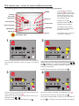
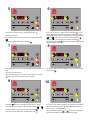
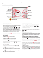
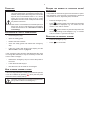
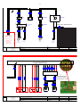
MIXER ERGO60, ERGO100, ERGO140 AR200 OPERATING INSTRUCTIONS 062015 ORDER NO.: 00453 GB Translation of the original user manual ERGO60 ERGO100 Operating instructions VL-4 ERGO140 AR200 06.05.2014 MG4220292, MG4220294, MG4220296 062015 ORDER NO.: 00453 GB Translation of the original user manual A/S Wodschow & Co. Kirkebjerg Søpark 6 DK-2605 Brøndby Phone: +45 43 44 22 88 [email protected] www.bearvarimixer.com 16.11.2015 2 Contents: General: . ...............................................................................................................................................................................2 Safety: . ...............................................................................................................................................................................2 Installation of new mixer:.............................................................................................................................................................2 Construction of the mixer:...........................................................................................................................................................3 Positioning the bowl in the mixer:.................................................................................................................................................3 Maximum capacity of the mixer:.....................................................................................................................................................4 Correct use of tools:..................................................................................................................................................................4 Maintenance and lubrication:.......................................................................................................................................................4 Cleaning: . ...............................................................................................................................................................................4 Recommended maximum speeds:......................................................................................................................................................4 Control Panel VL4:....................................................................................................................................................................5 Remix function:.............................................................................................................................................................................5 VL4 control panel - survey of various operating situations:........................................................................................................6 Operation of the mixer:................................................................................................................................................................8 Overload: . ...............................................................................................................................................................................9 Procedure in case of overloading:...............................................................................................................................................9 How to bring a mixer to stop:.......................................................................................................................................................9 Reading the number of operating hours/days/years:.....................................................................................................................9 Resetting the control system:.....................................................................................................................................................9 Mechanical component error:....................................................................................................................................................10 Error codes shown in display:....................................................................................................................................................10 Call up an error log of the last 10 disconnections:.................................................................................................................11 Error codes displayed in the error log:....................................................................................................................................11 Adjusting of bowl clamping and centering:................................................................................................................................12 Electrical-components:.............................................................................................................................................................14 Safety circuit:...........................................................................................................................................................................15 Electrical Diagrams:.................................................................................................................................................................16 To replace a belt:......................................................................................................................................................................18 To replace a lifting actuator:....................................................................................................................................................18 Replacing the Reed contacts:....................................................................................................................................................18 Fine-tuning Reed contacts and CE microswitch:.........................................................................................................................18 Lubrication overview:.................................................................................................................................................................20 General: In case of complaints, please contact your supplier. The guarantee does not cover faults resulting from faulty operation, overloading and lacking observance of directions of maintenance. It should be checked that all loose parts are delivered with the mixer such as bowl, tools, and rubber feet. Safety: The constant noise level of the workplace of the operator is lower then 70 dB (A). In all cases where the parts of the mixer are moving and the safety guard is not closed, it takes two hands to operate the mixer. The mixer is designed for manufacture of products which do not during processing cause reactions or emit substances which may be detrimental to the user. The mixer must be bolted securely to the floor. Load per leg not to exceed: ERGO60 - 2500 N AR200 - 4500 N ERGO100 - 3200 N ERGO140 - 4000 N Installation of new mixer: Installation and securing: The mixer must be fitted with rubber feet, which neutralize shaking. Spacers can be inserted under the mixer’s feet, if the floor is not completely even. Connection to power: Before the mixer is connected to power, it should be checked that the voltage and frequency printed on the machine label is correct in relation to the place of installation. The machine label is placed at the top right side of the mixer. Note: to be installed by a qualified electrician. Of functional and safety reasons, the machine must be connected to earth! Putting your fingers in the bowl while the mixer is running may cause injuries. Voltage at the installation: 50/60 Hz. Power: Phases x voltage With neutral Earth 3 x 380-480V +/-10% no Yes The machine label Voltage Phases 400V 3 Use Use neutral earth no Yes Remarks: Of functional and safety reasons, the machine must be connected to earth! 3 Construction of the mixer: Magnetic sensor, which is activated by the guard when the guard is closed. VL-4 control panel with Remix function See page 5 for an explanation of the panel. Safety guard – removable. Emergency stop The guard must be closed before the tool can rotate. The bowl can be raised with the guard open, but it will stop where the tool normally starts to rotate. The guard must be closed and two hands are required to lift the bowl the rest of the way. Bowl clamping system with inductive sensor: Bowl lift and “JOG”-function: At the back of the righthand bowl arm is an inductive sensor which is activated when the bowl is correctly positioned in the bowl clamping system (at the very back of the bowl arms). This sensor must be activated in order for the mixer to operate. If there is no contact between the bowl and the inductive sensor, the bowl cannot be lifted. will appear in the display, see “Error codes shown in display” on page 10. The mixer is provided with a “JOG”-function. Before the bowl reaches its top position, the tool starts rotating to dig its way into the ingredients. The bowl lift requires twohands operation for safety reasons. The bowl arms can move a little in case of maximum loading. Positioning the bowl in the mixer: The bowl arms must be lowered to their lowest position and the bowl pressed all the way to the back of the bowl arms. If there is no contact between the bowl and the inductive sensor, the bowl cannot be lifted. will appear in the display, see “Error codes shown in display” on page 10. If you have a bowl with “ears” it is important to place it correct in the mixer. Note: It is very important to orientate the bowl correctly so that the “third ear” is turned in towards the mixer Left “ear” Third “ear” Right “ear” 4 Maximum capacity of the mixer: Capacities per mix ERGO ERGO ERGO AR200 60 100 140 Egg white 9L 15 L 21 L 27L Whipped cream 15 L 45 L 75 L 120L Mayonnaise * 48 L 80 L 112 L 160L Layer cake base 15 kg 25 kg 35 kg 50kg Herb butter 45 kg 75 kg 105 kg 150kg Muffins * 33 kg 60 kg 85 kg 120kg Meatball mix 45 kg 75 kg 105 kg 150kg Icing 40 kg 70 kg 100 kg 140kg Mashed potatoes * 36 kg 65 kg 95 kg 140kg Bread dough (50%AR) ** 34 kg 58 kg 70 kg - Bread dough (60%AR) 44 kg 70 kg 80 kg - Ciabatta dough * (70%AR) 40 kg 75 kg 105 kg - Doughnut (50%AR) 36 kg 60 kg 90 kg - * Scraper recommended ** Low speed operation is recommended Tool Whip Beater Beater/whip Hook AR = Absorption Ratio (%AR) (Liquid in % of solids) Example: A basic recipe contains 1 kg of solids and 0,6 kg of liquid: This gives AR = 0,6 kgs x 100 = 60% 1 kg If for instance it is required to use the maximum capacity of the mixer, the calculated AR = 60% is used for determining the amount of solids and liquid in the dough: If a 140 L mixer is used, and a dough with AR = 60% is to be kneaded, the maximum capacity is = 80 kgs. Now the weight of solids in this dough is calculated: Solids = Max. capacity x100 = 80 kg x 100 = 50 kg AR + 100 60 + 100 Weight of liquid = 80 kg - 50 kg = 30 kg Local variations in the characteristics of the ingredients can influence water absorption, volume and baking characteristics, etc. Correct use of tools: Recommended applications for tools: See the section “Maximum capacity of the machine”. Whips should not be struck against hard objects as e.g. the edge of the bowl. This will make the life of the tool shorter due to increasing deformity. For production of mashed potatoes the special wing whip or the reinforced whip should be used, alternatively use the beater and the whip. Maintenance and lubrication: See lubrication overview on page 14. Cleaning: The mixer should be cleaned daily or after use. Press the emergency stop before wiping the control panel. The mixer should be cleaned with a soft cloth and clean water. Sulphonated soaps should be used with caution as they destroy the mixer’s lubricants. Never use high pressure cleaning for the mixer. Parts made of aluminum should not be used to strongly acidic, highly alkaline or highly salty foodstuffs, which may attack aluminum without coating Tools of aluminium must not be washed with strong alkaline detergents - The PH value should be between 5 and 8 Recommended maximum speeds: 5 Control Panel VL4: Text field / display Time up Displays operation time, programme numbers and error codes from the motor and frequency transformer Used to set operation time. The time can be set before/ after starting the mixer and can be changed while the mixer is running. REMIX Used to store a recipe. See the section ”REMIX function”. Bowl up Time down To raise the bowl, press the + + fields simultaneously and constantly until the bowl reaches the top. Used to set operation time. The time can be set before/ after starting the mixer and can be changed while the mixer is running. Fixed speeds Bowl down Four pre-defined speeds. Lowers the bowl once the mixer has stopped. If this field is activated while the mixer is running, the bowl will be lowered automatically when the mixer stops. Speed indicator Displays the running speed of the mixer. Speed down Used to change speed while the mixer is running. Speed up Pause Used to change speed while the mixer is running. Start/Stop Must always be used when inspecting the product in the bowl. Also used to reset the control system; see ”Resetting the control system”, page 9. Remix function: The special Remix-function is a shortcut to programming of recipes. While the mixer is operated, all commands are , is pushed, stored, and when a recipe is finished and it is possible to store the entire recipe under a program number. • There are 20 program numbers: 1, 2, 3, 4 - 11, 12, 13, 14 - 21, 22, 23, 24 - 31, 32, 33, 34 - 41, 42, 43, 44 • A program cannot be deleted, but can be replaced. • The programs are not deleted in case of no power How to store a program: Program number 12 in this example • Start by pressing • Run the whole recipe, including pauses, changes of speed and automatic lowering of the bowl. • Press to stop the mixer. • Keep depressed; the display shows • Continue pressing and press is shown on the display • Release 12 How to run a program: Program number 12 in this example: • First a short push on and then on and . Now appears in the text field and immediately thereafter the total length of the program will be shown. The program is run by pushing . • If the speed or the time is changed, when running a program, the program will be left and the mixer must be run manually. • If is pressed while a program is running, the mixer stops and quits the program. • If the safety guard is opened while a program is running, the mixer stops and will be displayed. When the safety guard is closed again, press ; twice; the first press eliminates the error code and the second press starts the mixer – the program quits. • If the program is containing a pause, the mixer will stop and at the same time an acoustic signal is heard. It is now possible to lower the bowl and open the safety guard. When the operator wants to restart the mixer, push and the program will be resumed. . and . as well, and the program will be stored as number 6 VL4 control panel - survey of various operating situations: The following pictures show various operating situations and corresponding explanation: REMIX Time up Text field Time down Bowl up Fixed speeds Bowl down Activation of the field keeps the chosen values for operation time and speed. Start/Stop The operation time and the speed can be changed while the mixer is running. Pause The operation time can be set to 90 min. as maximum. Speed indicator Speed down Speed up Emergency stop 1 If the field is activated while the mixer is running, the chosen operation time is reset and the speed is set to minimum. (The same when pushing emergency stop). 2 REMIX REMIX There is no power connection to the mixer or the emergency stop has been activated - there is no light in the control panel. There is power connection to the mixer and the bowl is not in its top , position. The bowl can be raised by activating the fields and simultaneously - diodes in the fields are flashing! The mixer cannot be started until after the bowl has been raised to its top position. The bowl can be lowered by activating the field 3 . 4 REMIX REMIX The bowl is in its top position and the mixer is ready for ope ration by activation of the field . Speed can be chosen. Operation time can be chosen by acor . tivating the fields The bowl can be lowered by activating the field . The mixer is ready for operation by activating the field The bowl can be lowered by activating the field . . One of the four fixed speeds is chosen by a short activation of the field - six diodes on the speed indicator are flashing. 7 5 6 REMIX The mixer is ready to run by activating the field REMIX is conThe mixer is running - green diode in the field stantly alight when the chosen speed has been reached. The operation time can be changed by activating the fields and . The mixer can be paused by pressing . . Speed 2 is chosen. An operation time has been chosen by activating the field The bowl can be lowered by pressing . The mixer can be stopped by activating the field the bowl is automatically lowered By activating the field when the mixer stops. . 7 8 REMIX REMIX The safety guard has been opened while the mixer was running. As figure 6, but automatic lowering of the bowl is selected by pressing . The bowl can be lowered. When the safety guard is closed and the operator presses twice, the mixer starts at its lowest speed. 9 10 REMIX The field REMIX The mixer runs and an operation time has been indicated. has been activated and the mixer is ready. The time can be changed by activating the fields or The bowl can be lowered by activating the field . The mixer can be started by activating the field . . Automatic lowering of bowl at ended operation time has been chosen - see position 6. When activating the field or automatic lowering of bowl is deactivated and can not be chosen again. 8 Operation of the mixer: REMIX Time up Text field Time down Bowl up Fixed speeds Bowl down Speed indicator Start/Stop Speed down Speed up Pause Emergency stop Before starting the mixer: Indication of operation time: Mount the required tool in the bayonet shaft. Place the bowl in the bowl arms and close the safety guard. Before starting the mixer, an operation time for the mixer and . can be chosen by adjusting the time on If the field is activated for longer time, the speed is increased/reduced quicker. To raise the bowl, activate the fields , and simultaneously, the activation to be continued until the bowl has reached its top position. When the bowl is approx. 20 cm from its top position, the tool will start to rotate in low speed. The rotation of the tool and the bowl will stop automatically when the bowl is in its top position. The red diode in the field the mixer is ready. is now alight to show that Start the mixer: to start the mixer. Activate the field to increase the speed. Activate the field to reduce the speed. Four fixed speeds: For quick choice of speed, use the fields Automatic lowering of bowl: Once the mixer has been started, the operator can make the mixer lower the bowl automatically when it stops by pressing . The diode in the field is flashing after the activation. Inspection of the ingredients during operation: Activate the field The speed indicator below the fields mixing speed of the tool. Minutes and seconds are shown in the text field between and . If it is wished to stop the mixer without affecting the operation time, the field can be activated. The mixer will reduce speed and then stop, the operation time will also stop. If the guard is opened, the display shows , but the operation time is displayed again when the guard is closed. to shows the to . Field corresponds lowest speed. Field corresponds approx. 30% of maximum speed. Field corresponds approx. 60% of maximum speed. Field corresponds maximum speed. and the mixer will Close the safety guard and press start at the lowest speed. The operation time continues from before. Lowering of bowl: When the ingredients in the bowl have been mixed, the mixer is stopped by activating the field .The bowl is lowered by activating the field . When the bowl has reached its bottom position, the safety guard can be opened. 9 Overload: Do not overload the mixer. Sticky and heavy doughs can overload the mixer. Overloading is further exacerbated if the speed of the mixing tool is increased beyond the recommended values or if a wrong mixing tool is used. Large lumps of fat or cooled ingredients must be cut into small parts before they are placed in the bowl. If the mixer is overloaded for an extended period, it will cut out. An error code will show on the display. Follow the instructions for ”Procedure in case of overloading” Reading the days/years: It is possible to read how long the mixer has been in operation (operation = tool revolving). The total time is read as a combination of hours, days and years; see below: • Press the emergency stop • Press and the number of hours the mixer has been operating will be displayed, e.g.: if it shows 157, this means 1 hour and 57 minutes • Press and the number of years and days the mixer has been operating will be displayed, e.g.: if it shows 1120, this means 1 year and 120 days. Procedure in case of overloading: • Push emergency stop. • Open the safety guard. • Reduce the bowl contents. • Close the safety guard and release the emergency stop. • If the error code is still shown on the display, see the “Error codes” section on page 10. If the emergency stop has been activated while the mixer is running with a full bowl, it may be necessary to lower the bowl in order to empty it. • Release the emergency stop to connect the power to the mixer. • Lower the bowl and empty it. • Now the mixer can be used as normal again. How to bring a mixer to stop: If the mixer stopped after the safety guard has been opened, it can be re-started by pressing twice (the first press resets the mixer’s safety switch). The mixer should only be stopped using the emergency button if there is an emergency. number of operating hours/ Resetting the control system: • Press the emergency stop • Press for 10 seconds. 10 Mechanical component error: The bowl is too tight or too loose in the bowl arms. Solution: “Adjustment of bowl clamping and centering”, page 12 The tool hits the sides of the bowl. olution: “Adjustment of bowl clamping and centering”, page 12 S Abnormal noise from the lifting actuator: Solution: Lubrication of actuator; see lubrication chart on page 14 Error codes shown in display: The error codes shown on the display are from the motor or the frequency transformer: Motor error codes: Code Error Solution EE1 The CE switch interrupted the safety circuit when the mixer started Check that the CE switch is closed with the bowl in the top position EE2 The safety guard is open If the guard is opened while the tool is not rotating, the error code will be eliminated when the guard is closed. If the guard is opened while the tool is rotating, closing the will eliminate the error code. guard and pushing EE3 The bowl is not correctly positioned, so the inductive sensor has not been activated Check that the bowl is positioned correctly – if the bowl ring has three “ears”, the middle ear must point in towards the body of the mixer, otherwise the bowl must be lowered again and turned to the correct position. (It is possible to lower the bowl even if the error code is displayed.) If/when the bowl is positioned correctly, push it right back into the bowl arms, the inductive sensor will then be activated and you can lift the bowl. If contact between the sensor and bowl is interrupted again, the error code will appear in the display. It is still possible to lift the bowl during the first 5 seconds when the error code is shown, after this the lifting movement will be deactivated. Push the bowl right back into the bowl arms again so that contact is re-established between the bowl and sensor. The error code will disappear and you can lift the bowl again. EE4 The thermal sensor in the motor has overheated EE5 The overcurrent switch to the lifting motor has tripped. Reduce the quantity of ingredients in the bowl. Once the cause of the problem is found and the problem has been fixed, reset the overcurrent switch by pressing the blue button on the switch, see ill. The overcurrent switch is in the electrical box Reason: The bowl arms have reached the physical end stop but the lifting motor has not cut out. Check that the reed contacts, located on the outer tube of the lifting motor spindle, have been activated (the yellow diode on the contact illuminates) when the bowl arms are at the top or bottom. If the reed contacts do not activate, they must be replaced Reason: The bowl has too great a quantity of ingredients. Reduce the quantity of ingredients in the bowl EE6 The panel is not connecting with the frequency transformer. Check the connection. EE7 There is a fault with the frequency transformer. Check the error log to ascertain the error code; see page 11 11 Call up an error log of the last 10 disconnections: The last 10 disconnections due to errors resulting in code can be read on the mixer display: • Press the emergency stop • Press • The diodes on the speed indicator light up. The age of the error is indicated by the diode that illuminates: and to browse the log The first diode lights up – the last (most recent) error code is displayed The second diode lights up – the second-last error code is displayed The third diode lights up – the third-last error code is displayed, etc. Error codes displayed in the error log: Display on the mixer Reason for error User Engineer Fault correction Frequency transformer display Error description 1 Error in frequency transformer Call the engineer UU DC bus undervoltage 2 Error in frequency transformer Call the engineer OU DC bus overvoltage 3 Overloading of the frequency transformer Reduce the quantity in the bowl OI.AC Overcurrent at drive output 4 Overloading of the frequency transformer Reduce the quantity in the bowl OI.br Braking IGBT transistor overcurrent 6 1 phase of supply voltage missing Call the engineer ph.AC Loss of a motor phase with brake enabled 7 ?? OSP Over speed 19 Overloading of the frequency transformer Reduce the quantity in the bowl it.br Braking resistor overload I x t 20 Overloading of the motor Reduce the quantity in the bowl it.AC Motor overload I x t 21 Overloading of the frequency transformer Reduce the quantity in the bowl Oht1 IGBT overheating detected by internal sensor 22 Overloading of the frequency transformer Reduce the quantity in the bowl Oht2 Internal braking resistor overheating detected by thermal sensor 24 Overloading of the motor Reduce the quantity in the bowl th Motor thermal sensor has tripped 26 Error in frequency transformer Call the engineer O.Ld1 Overload on the +24V power supply or digital 27 Error in frequency transformer Call the engineer CL1 Loss of the current reference on analog input ADI1 28 Error in frequency transformer Call the engineer CL2 Loss of the current reference on analog input ADI2 29 Error in frequency transformer Call the engineer CL3 Loss of the current reference on analog input ADIO3 30 Connection broken between panel and frequency transformer Call the engineer SCL Loss of serial link communication 31 Error in frequency transformer Call the engineer EEF EEPROM trip or transfer problem with XPressKey (drive and key version different) 33 Error in motor Call the engineer rS Trip during measurement of the stator resistance 34 Error in frequency transformer Call the engineer Fbus Disconnection of the fieldbus during operation or error detected by the bus option 35 Connection broken from saftey circuit to frequency transformer Call the engineer Secd Secure disable input trip 36 Error in voltage supply to the mixer Call the engineer Enc1 Loss of channel U 37 Error in voltage supply to the mixer Call the engineer Enc2 Loss of channel V 38 Error in voltage supply to the mixer Call the engineer Enc3 Loss of channel W 12 Adjustment of bowl and ERGO100: centering ERGO60 First find the present bowl centering: mount the beater and the bowl, then raise the bowl arms up to normal working position. With your hand turn the beater, and then measure the distance between beater and bowl edge. By removing the rear covering the bowl arm guide plate is now accessible (E). Loosen the screws (D) and move the bowl arm guide plate in the required direction. Again turn the beater and measure the distance between beater and bowl. When the bowl has been centred, fasten the bowl arm guide plate in the new position and screw on the rear covering. Adjustment ERGO100: of bowl fixing ERGO60 and The bowl arms must be raised to normal working position. The adjusting diameter (Y) shall be measured inside between the bowl arms: Adjusting diameter (Y): AE60 = 450,4 mm AE100 = 554 mm In case the bowl fastening is too tight, remove the lock ring (B) and draw the bearing (A) from the shaft (C). The bearing should be turned 180o and be mounted on the shaft again. It might be necessary to turn both bearings. At last check the bowl centering and if necessary, adjust. The bearing (A) has two diameters. As standard the mixer is delivered with the bearings mounted so that the largest diameter points away from the bowl arms, which means the tightest bowl clamping. 13 Adjusting of bowl clamping and centering ERGO140and AR200: In the rear part of the bowl arms (J) a shaft with an eccentric stud (K) has been mounted, on which the ball bearing is mounted. By turning the eccentric stud, the bowl arms can be opened and closed so that the clamping and the centering of the bowl can be adjusted. It has to be observed that the shaft is mounted in the bowl arm with a thread so that when the eccentric stud is turned, the whole shaft is turned out and in into the bowl arms. When exchanging the whole shaft, the right starting point for the adjustment must be found first. The ball bearing (L) must be in the middle of the guide plate (M) so that the width of the entire ball bearing is fitting tightly against the guide plate, and at the same time it has to be observed that the eccentric stud cannot hit the back plate when the adjustment has been finished. In order to counteract that the eccentric shaft turns loose by itself when the mixer is working, the eccentric shaft must be self-tightening. In order to obtain this effect, the below drawings must be followed, on which the adjusting area for the left and the right bowl arm, resp. is shown. First find the bowl centering, e.g. by mounting bowl and beater in the mixer, and turn the beater round with your hand, and measure the distance from the beater to the edge of the bowl. • When adjusting the clamping and centering of the bowl, the bowl arms must be raised into working position. When exchanging the shaft with eccentric stud (K) the bowl arms must be lowered. • First open the lock plate (N). • Loosen the shaft counter nut (P), use span 46. • Screw an M8 bolt with counter nut (R) into both the eccentric studs (K), and tighten the counter nuts. If the shaft with the eccentric stud has stuck in the bowl arm, it can be loosened with a key with the span 36. • By turning the eccentric studs the clamping and the centering of the bowl can be adjusted. • Remember to use the right adjusting area for right and left bowl arm. The drawings show the adjusting area for • When the adjustment is correct, tighten the shaft counter nuts (P). Hold the bolt (R) while the shaft counter nut is tightened. • Knock the lock plate (N) in position. • Remove bolt and counter nut Movement of the bowl arm Adjusting area for right bowl arm, seen from behind. Loose bowl clamping Tight bowl clamping Movement of the bowl arm Tight bowl clamping Loose bowl clamping Adjusting area for left bowl arm, seen from behind. Adjusting diameter (Y) = 607 mm 14 Electrical-components: ¢¥ ¦ ¤ ¦ ¢¢ ¢ ¤ ¦ ¤ ¦ ¤ ¢ ¦ ¤ ¢¥ ¥ ¤ ¦ ¤ ¦ ¤ ¥ ¦ ¤ ¦ ¤ ¥ ¦ ¦ ¢ ¢¥ ¦ ¤ ¢¥ ¢¥ ¢¥ ¥ ¢¥ ¤ ¢¥ ¦ ¦ ¤ ¦ ¢¥ ¦ ¤ ¢ ¤ ¢¢¢ ¢ ¨ ¤ ¢¥ ¢ ¥ ¥ ¥ ¥ ¢¢¢ ¤ ¤ ¦ ¢ ¢¥ ª § § § § § § § ¥ ¥ ¥ ¤ ¥ £ £ ¢¢ £ ¢ ¤ ¢ ¢¢ £ ¢ £ ¢ ¢ ¤ ¤ ¢ ¢ ¢ ¢ ¤ ¢ ¤ £ ¤ ¤ ¢ ¢¢ £ ¢ ¤ ¤ ¤ ¢ ¤ © ¢ ¢ ¢ ¤ ¢¤ ¢ ¢ ¢¢ £ ¢ ¢ ¢ ¢ £ ¢¢ £ ¢ ¢¢ £ ¢ © ¢ ¢¢ ¡ ¢ ¢ ¢ 15 Safety circuit: ¡ Electrical Diagrams: 0 16 1 2 3 4 5 6 7 8 PE 9 2.0 FG AC/ AC/ N L (L2) (L1) L3 L2 L1 L3 3/1 RFI filter RFI filter L2 L1 TB1 -Q2 3 1 -T1 -BK1 3/1 -R1 2 PE BK GY BN BK GY BN BK GY BN FRAME 400VAC/24VDC Power supply Solid state relay Direktion control m˂ 3 PE 4 3 2 L3 DC OUTPUT -V 5 3 1 1,8-2,6A -F1 Motor protection Direktion control 6 2 4 3/5 BK GY BN PE W DC OUTPUT +V 1 BK BK BK L3 L2 L1 TB2 400VAC/24VDC 0-5A Frequency inverter Main motor U 3/3 3/3 3/6 V -Q1 L2 L1 EMR4-F500-2 Phase sequencing relay BU L+ VT L- 2.0 2.0 BU VT WH WH BK GY BN 3 3 x 400V AC + PE Power supply Max. 16A 3 -M1 -K3 A2 PE W1 M A1 M V1 U1 PE V1 U1 208V AC - 380V AC 220V AC - 400 V AC 230V AC - 415 V AC 250V AC - 440V AC W1 BK GY BN PE L3 L2 L1 BK GY BN FRAME 3/6 -M2 3/4 Break resistor Main Motor Lift Motor Safety relay Stop time (PTO in motor) Customer supplied Project title: CE * Ergo 60 VL-4 - Ergo 100 VL-4 - Ergo 140 VL-4 Page title: Main power File name: Ergo 60 VL4.8-CE A/S WODSCHOW & CO Kirkebjerg Søpark 6 DK-2605 Broenby www.bearvarimixer.dk 0 1 2 Subject name: Project rev.: Drawing no.: Const. (project/page): Appr. (init/date): 3 4 5 Page rev.: Last printed: Last corrected: / / 6 Rev. 8 27-10-2015 27-10-2015 7 Page 1 Previous page Next page Number of pages: 2 5 8 9 -K1 3/0 4/0 J2 J2 BN J2 14 J2 GN J2 WH J2 13 J2 S34 J1 RD J1 OG J1 S33 J1 42 J1 BE J1 41 J1 YE J1 PK Front Panel Print J8 J8 J2 -R2 A2 -K2 A1 BU VT Ferrits Beads + - Nc. Nc. Reset Reset No. No. Emergency switch A/S WODSCHOW & CO Kirkebjerg Søpark 6 DK-2605 Broenby www.bearvarimixer.dk Project title: CE * Ergo 60 VL-4 - Ergo 100 VL-4 - Ergo 140 VL-4 Page title: Coltrol Voltage File name: Ergo 60 VL4.8-CE 23 S21 S12 WHGN WHBN S22 BN BU BK -B2 GY GY BK GY BK BU BN YEBN OGBN BN BU -B1 24 11 -S2 12 1 2 -S1 2 1 BU BN BK GY GYGN OGRD GYRD BNRD GYBK WHRD RDBK BUBK S11 Safety relay 1.9 L+ 1.9 L1.9 PE CE switch Magnetic switches Magnetic switches Subject name: Project rev.: Drawing no.: Const. (project/page): Appr. (init/date): Page rev.: Last printed: Last corrected: / / Rev. 8 27-10-2015 27-10-2015 Page 2 Previous page Next page Number of pages: 3 5 17 0 1 2 3 4 5 6 7 8 PE 9 2.0 FG AC/ AC/ N L (L2) (L1) L3 L2 L1 L3 -Q2 3/1 RFI filter RFI filter L2 L1 TB1 -R1 3 1 -T1 -BK1 3/1 2 PE BK GY BN BK GY BN BK GY BN FRAME 400VAC/24VDC Power supply Solid state relay Direktion control m˂ 3 PE 3 4 DC OUTPUT -V 2 DC OUTPUT +V 5 3 1 1,8-2,6A -F1 Motor protection Direktion control 6 2 4 3/5 Wire code, IEC/EN 60757 BK GY BN PE W L3 400VAC/24VDC 0-5A 1 BK BK BK L3 L2 L1 TB2 Phase sequencing relay Frequency inverter Main motor U 3/3 3/3 3/6 V -Q1 L2 L1 EMR4-F500-2 BU VT WH WH BK GY BN 3 -M1 -K3 A2 PE W1 M A1 M V1 U1 PE V1 U1 3 x 400V AC + PE Power supply Max. 16A W1 BK GY BN PE L3 L2 L1 BK GY BN 3 3/6 -M2 3/4 Break resistor Main Motor Lift Motor Safety relay Stop time (PTO in motor) Customer supplied Project title: CE * Ergo 60 VL-4 - Ergo 100 VL-4 - Ergo 140 VL-4 Page title: Main power File name: Ergo 60 VL4.8-CE A/S WODSCHOW & CO Kirkebjerg Søpark 6 DK-2605 Broenby www.bearvarimixer.dk 0 1 2 Subject name: Drawing no.: Const. (project/page): Appr. (init/date): 3 4 5 L+ VT L- 2.0 2.0 BE BEIGE BK BLACK BN BROWN BNBU BROWNBLUE BNGN BROWNGREEN BNRD BROWNRED BU BLUE BUBK BLUEBLACK BUGN BLUEGREEN GN GREEN GNBK GREENBLACK GY GREY GYBK GREYBLACK GYBN GRAYBROWN GYBU GREYBLUE GYGN GREYGREEN GYRD GREYRED GYVT GREYVIOLET OG ORANGE OGBU ORANGEBLUE OGGN ORANGEGREEN OGGY ORANGEGREY OGBN ORANGEBROWN Project rev.: Rev. 8 FRAME 208V AC - 380V AC 220V AC - 400 V AC 230V AC - 415 V AC 250V AC - 440V AC BU Page rev.: Last printed: Last corrected: / / 6 OGRD PK RD RDBK RDBU RDGN VT WH WHBK WHBU WHGY WHOG WHRD WHVT WHYE WHGN WHBN YE YEBK YEBU YEGY YEBN 27-10-2015 27-10-2015 7 ORANGERED PINK RED REDBLACK REDBLUE REDGREEN VIOLET WHITE WHITEBLACK WHITEBLUE WHITEGREY WHITEORANGE WHITERED WHITEVIOLET WHITEYELLOW WHITEGREEN WHITEBROWN YELLOW YELLOWBLACK YELLOWBLUE YELLOWGREY YELLOWBROWN Page 1 Previous page Next page Number of pages: 2 5 8 9 -K1 3/0 4/0 J2 J2 BN J2 14 J2 WH J2 13 J2 GN J2 RD J1 S34 J1 S33 J1 OG J1 BE J1 42 J1 41 J1 YE J1 PK Front Panel Print J8 J8 J2 -R2 A2 -K2 A1 BU VT Ferrits Beads + - Nc. Nc. Reset Reset No. No. Emergency switch A/S WODSCHOW & CO Kirkebjerg Søpark 6 DK-2605 Broenby www.bearvarimixer.dk Project title: CE * Ergo 60 VL-4 - Ergo 100 VL-4 - Ergo 140 VL-4 Page title: Coltrol Voltage File name: Ergo 60 VL4.8-CE 23 S21 S12 WHGN WHBN S22 BN BU BK -B2 GY GY GY BK BU BN YEBN OGBN BK BN BU -B1 Deep-switche must be in OFF-position, as they are not in use 24 11 -S2 12 1 2 -S1 2 1 BU BN BK GY GYGN OGRD GYRD BNRD GYBK WHRD RDBK BUBK S11 Safety relay 1.9 L+ 1.9 L1.9 PE CE switch Magnetic switches Magnetic switches Subject name: Project rev.: Drawing no.: Const. (project/page): Appr. (init/date): Page rev.: Last printed: Last corrected: / / Rev. 8 27-10-2015 27-10-2015 Page 2 Previous page Next page Number of pages: 3 5 18 To replace a belt: The old belt can be removed by loosening the belt tightener. Installing a new belt: 1. Place the belt in the wheel groove. 2. Tighten the belt using the belt tightener 3. Tighten the belt until the belt can be bent approximately 9 mm (dL) at a pressure of approx. 9 kg (F), see Fig. 2. 4. Run the machine with a regular production load for approximately 10 min. 5. Check the belt tension by measuring its elasticity. If the elasticity has changed, retighten as described in point 3. The belt tension should be checked every 6 months. If there is not enough belt tension, the belt will wear out quickly, and if there is too much tension, there is a risk that the life-span of the bearings will be considerably shortened. Then follow the section “Fine-tuning the reed contacts and CE microswitch” on page 19. The lifting actuator has 3 proximity detectors (reed contacts) that check the position of the bowl. Replacing the Reed contacts: Remove the incorrectly charged contact and install the new contact according to Fig. 3. Connect the cable as shown in the illustration on page 14. Follow the instructions below to secure the reed contact in the correct position. Fine-tuning Reed microswitch: c o n ta c t s a n d CE Check that the location of the reed contacts matches up with the marks in Fig 3. Connect the reed contacts with the matching cables – see illustration on page 14. Adjust the three contacts and the CE microswitch according to the following sequence: CC dL F If replacing the lowest actuator fittings, use Lochtite 270 to tighten the fittings. 1. Adjusting the top reed contact: Contact A determines the top position of the bowl. The contact must be positioned in accordance with the mark in Fig. 3. Raise the bowl to the position corresponding to mark X, Fig. 5. Fig. 2. Belt tension. To replace a lifting actuator: Adjust the top reed contact upwards until the reed LED lights up – it is important to stop adjusting once the LED lights up! 2. Adjusting CE-microswitch: Lift the bowl arms to the top position. ERGO60 and ERGO100, se Fig. 4, page 19. Lower the bowl arms to a pressure relief point set at approx. midway. ERGO140 and AR200, se Fig. 4a, page 19. It is very important that the bowl arms are lowered to a pressure relief point before disassembling the lifting actuator. Cut the power to the machine by removing the plug from the socket. Remove the three plugs for the reed contacts on the actuator. Remove the lifting actuator from the bowl arms by removing the pins and axle. 3. Adjusting the reed contact for the JOG function Contact B determines where the machine’s JOG function starts, see also “Bowl lifting and JOG function” on page 3. The contact must be positioned as shown in Fig. 3 and does not require any further adjustment. 4. Adjusting the bottom reed contact: Contact C determines the bottom position of the bowl. Remove the cotter pin that secures the actuator at the top. The contact must be positioned in accordance with the mark in Fig. 3. Remove the cable to the actuator and lift the actuator out from the mixing machine. Raise the bowl to the position that corresponds to mark Y in Fig. 5. Install the new actuator. Adjust the bottom reed contact until the reed LED lights up – it is important to stop adjusting once the LED lights up Connect the machine to the power supply. 19 A A B ERGO60: A = 35 mm B = 230 mm C = 520 mm ERGO100: A = 60 mm B = 250 mm C = 630 mm ERGO140: A = 15 mm B = 200 mm C = 633 mm AR200: A = 90 mm B = 240 mm C = 495 mm Fig 4 Adjusting the CE microswitch on ERGO60 and ERGO100: The measurement A must be 38 mm. D F E C Fig 4a Adjusting the CE microswitch om ERGO140 and AR200: Fig. 4 D. Loosen CE microswitch Push the microswitch completely into the switch housing E. Fig. 3 Pull the microswitch back 1 mm so that there is 1 mm of air between the contact and the housing, see F. Tighten the screws that hold the CE microswitch in place. The distance X corresponds to the top position of the bowl, and the distance Y corresponds to the bottom position of the bowl. The distances are measured from the underside of the bayonet shaft to the surface of the bowl arms on which the bowl is resting. X/Y A/S WODSCHOW & Co. X/Y Surface: Industrisvinget 6 DK-2605 Broendby www.bearvarimixer.dk Dimension: Date: 26-05-2010 Design: Stroke 616mm Matr: Fig. 5 X = 178 mm Y = 663 mm ERGO100 X = 297 mm Y = 860 mm ERGO140 X = 303,25 mm Y = 919 mm X = 378 mm Y = 780 mm Scale: ERGO60 A3 Format: AR200 MH Rev: 20 Lubrication overview: Part Location Oil/grease Bushings in the bowl arms Fig.6 Item A, Organic oil or grease, e.g Texaco StartPlex EP Remove the back cover. Lubricate the bowl arm axle with grease. Item B, Organic oil or grease, e.g Texaco StartPlex EP Remove the back cover. Lubricate the bearing and track with grease. Item C, Gearwheel and sprocket Molub Alloy 036SF Heavy or Castrol Grippa 355. Needle bearings should not be lubricated with this type of lubricant.. The mixer head may only be repaired by an authorised technician. During repairs Item D, Always use spindle grease: Mobilith SCH 460 from Mobil. The gear of the actuator is lubricated for life and does not need to be serviced. The spindle and the spindle nut in the actual actuator (Fig 6a) are not lubricated for life and therefore need relubricating. The actuator is thoroughly lubricated on delivery. Relubricating (Fig 6a): • Run the actuator away from bottom dead centre (bottom dead centre is when the actuator’s piston is not run out). • Fill max. 2 ml lubricant via the grease nipple (shown in the diagram below). • Run the actuator in the bottom position before it is used again. Min. every 6 month, or in case of unusual noises or vibrations. The spindle nut “screams” if there is insufficient lubrication. It is important to keep the spindle well lubricated because this is important for the lifespan of the nut. However, there should not be too much grease because this can be squeezed out of the actuator and potentially get into the gears. Lifting guide Fig.6 Mixer head Lifting actuator AK00131 Fig.6 Fig.6 C Explanation Per 5,000 batches or min. once yearly or in case of unusual noise. D Grease Grease nippel nipple for spindel nut A B Fig. 6 Frequency Lubrication overview Fig. 6a 21 Indhold af CE Overensstemmelseserklæring, (Maskindirektivet, 2006/42/EC, Bilag II, del A) Contents of the EC Declaration of conformity for machinery, (Machinery Directive 2006/42/EC, Annex II., sub. A) Inhalt der EG-Konformitätserklärung für Maschinen, (Richtlinie 2006/42/EG, Anhang II, sub A) Contenu de la Déclaration CE de conformité d’une machine, (Directive Machine 2006/42/CE, Annexe II.A) Inhoud van de EG-verklaring van overeenstemming voor machines, (Richtlijn 2006/42/EC, Bijlage II, onder A) Contenido de la declaración "CE" de conformidad sobre máquinas, (Directiva 2006/42/EC, Anexo II, sub A) Fabrikant; Manufacturer; Hersteller; Fabricant; Fabrikant; Fabricante: Adresse; Address; Adresse; Adresse; Adres; Dirección: DK GB DE FR NL ES A/S Wodschow & Co. ………………………………………………………………….…… Kirkebjerg Søpark 6, DK-2605 Brøndby, Denmark ………………………………………………………………………. Navn og adresse på den person, som er bemyndiget til at udarbejde teknisk dossier Name and address of the person authorised to compile the technical file Name und Anschrift der Person, die bevollmächtigt ist, die technischen Unterlagen zusammenzustellen Nom et adresse de la personne autorisée à constituer le dossier technique naam en adres van degene die gemachtigd is het technisch dossier samen te stellen nombre y dirección de la persona facultada para elaborar el expediente técnico Navn; Name; Name; Nom; Naam; Nombre: Adresse; Address; Adresse; Adresse; Adres; Dirección: Sted, dato; Place, date; Ort, Datum; Lieu, date ; Plaats, datum ; Place, Fecha: Kim Jensen ………………………………………………………………………. Kirkebjerg Søpark 6, DK-2605 Brøndby, Denmark ......................................................................... Brøndby, 15-12-2009 ........................................................................ Erklærer hermed at denne røremaskine Herewith we declare that this planetary mixer Erklärt hiermit, dass diese Rührmaschine Déclare que le batteur-mélangeur ci-dessous Verklaart hiermede dat Menger Declaramos que el producto batidora er i overensstemmelse med relevante bestemmelser i Maskindirektivet (Direktiv 2006/42/EC) is in conformity with the relevant provisions of the Machinery Directive (2006/42/EC) konform ist mit den Bestimmungen der EG-Maschinenrichtlinie (Direktiv 2006/42/EG) Satisfait à l’ensemble des dispositions pertinentes de la Directive Machines (2006/42/CE) voldoet aan de bepalingen van de Machinerichtlijn (Richtlijn 2006/42/EC) corresponde a las exigencias básicas de la Directiva sobre Máquinas (Directiva 2006/42/EC) er i overensstemmelse med følgende andre CE-direktiver is in conformity with the provisions of the following other EC-Directives konform ist mit den Bestimmungen folgender weiterer EG-Richtlinien Est conforme aux dispositions des Directives Européennes suivantes voldoet aan de bepalingen van de volgende andere EG-richtlijnen está en conformidad con las exigencias de las siguientes directivas de la CE 2004/108/EC ……………………………………………………………………………………………………………………………………... Endvidere erklæres det And furthermore, we declare that Und dass Et déclare par ailleurs que En dat Además declaramos que at de følgende (dele af) harmoniserede standarder, er blevet anvendt the following (parts/clauses of) European harmonised standards have been used folgende harmonisierte Normen (oder Teile/Klauseln hieraus) zur Anwendung gelangten Les (parties/articles des) normes européennes harmonisées suivantes ont été utilisées de volgende (onderdelen/bepalingen van) geharmoniseerde normen/nationale normen zijn toegepast las siguientes normas armonizadas y normas nacionales (o partes de ellas) fueron aplicadas EN454:2000 ; EN60204-1:2006; EN12100-1:2005 ……………………………………………………………………………………………………………………………………... EN12100-2:2005; EN61000-6-1:2007; EN61000-6-3:2007 ……………………………………………………………………………………………………………………………………... 22 Innehåll i EG-försäkran om maskinens överensstämmelse, (Maskindirektivet 2006/42/EG, bilaga 2, A) Contenuto della dichiarazione CE di conformità per macchine, (Direttiva 2006/42/CE, Allegato II, parte A) Sisukord EÜ masina vastavusdeklaratsioon , (Masinadirektiiv 2006/42/EÜ, lisa II, punkt A) Treść Deklaracja zgodności WE dla maszyn (Dyrektywa maszynowa 2006/42/WE, Załącznik II, pkt A) Sisältö EY-vaatimustenmukaisuusvakuutus koneesta (Konedirektiivi 2006/42/EY, Liite II A) Tillverkare; Fabbricante; Tootja; Producent; Valmistaja: Adress; Indirizzo; Aadress; Adres; Osoite: SE IT EE PL FI A/S Wodschow & Co. ………………………………………………………………….…… Kirkebjerg Søpark 6, DK-2605 Brøndby, Denmark ………………………………………………………………………. Namn och adress till den person som är behörig att ställa samman den tekniska dokumentationen: Nome e indirizzo della persona autorizzata a costituire il fascicolo tecnico Tehnilise kausta volitatud koostaja nimi ja aadress Imię i nazwisko oraz adres osoby upoważnionej do przygotowania dokumentacji technicznej Henkilön nimi ja osoite, joka on valtuutettu kokoamaan teknisen tiedoston Namn; Nome e cognome; Nimi; Imię i nazwisko; Nimi: Adress; Indirizzo; Aadress; Adres; Osoite: Ort och datum; Luogo e data; Koht, kuupäev; Miejscowość, data; Paikka, aika: Kim Jensen ………………………………………………………………………. Kirkebjerg Søpark 6, DK-2605 Brøndby, Denmark ......................................................................... Brøndby, 15-12-2009 ........................................................................ Försäkrar härmed att denna blandningsmaskin Con la presente si dichiara che questo mixer planetaria Deklareerime käesolevaga, et Planetaarmikseri Niniejszym oświadczamy, że mikser planetarny vakuuttaa, että tämä mikseri tyyppi överensstämmer med tillämpliga bestämmelser i maskindirektivet (2006/42/EG) is è conforme alle disposizioni della Direttiva Macchine (Direttiva 2006/42/CE) vastab kehtivatele masinadirektiivi (2006/42/EÜ) nõuetele spełnia wymagania odpowiednich przepisów dyrektywy maszynowej (2006/42/WE) on konedirektiivin (2006/42/EY) asiaankuuluvien säännösten mukainen överensstämmer med bestämmelser i följande andra EG-direktiv è conforme alle disposizioni delle seguenti altre direttive CE vastab järgmiste EÜ direktiivide nõuetele spełnia wymagania przepisów innych dyrektyw WE on seuraavien muiden EY-direktiivien säännösten mukainen 2004/108/EC ……………………………………………………………………………………………………………………………………... Vi försäkrar dessutom att e che Lisaks ülaltoodule deklareerime, et Ponadto oświadczamy, że ja lisäksi vakuuttaa, että följande (delar/paragrafer av) europeiska harmoniserade standarder har använts sono state applicate le seguenti (parti/clausole di) norme armonizzate kasutatud on järgmisi Euroopa harmoniseeritud standardeid (või nende osi/nõudeid) zastosowano następujące części/klauzule zharmonizowanych norm europejskich seuraavia eurooppalaisia yhdenmukaistettuja standardeja (tai niiden osia/kohtia) on sovellettu EN454:2000 ; EN60204-1:2006; EN12100-1:2005 ……………………………………………………………………………………………………………………………………... EN12100-2:2005; EN61000-6-1:2007; EN61000-6-3:2007 ……………………………………………………………………………………………………………………………………... 23