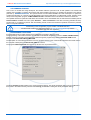
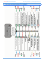
1
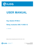
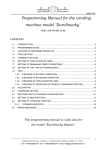
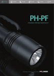
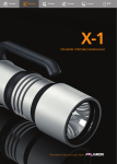
CORNERING LIGHTING MODULE
CLM02-CAN
INSTALLATION MANUAL
QUASAR ELECTRONICS
ul. Cieślewskich 25K
03-017 Warszawa
tel. (22) 427-31-41..44
http://www.quasarelectronics.pl
e-mail: [email protected]
OPERATION WITH USB BOOTLOADER
The firmware can be updated with the USB Bootloader programming interface available from
Quasar Electronics
REVISION: 2011.04.25_RB
CLM02-CAN MODULE INSTALLATION MANUAL
http://www.quasarelectronics.pl, e-mail: [email protected]
GENERAL INFORMATION
The CLM02-CAN module is designed for mounting in cars with +12V electrical installation equipped with CAN-bus. The
module interpreting CAN-bus messages realizes number of functions that inrease driving safety and comfort:
Passive lighting the corners using fog headlights (halogens) during turning the car;
Controlling of the front parking sensors;
Day ligths realized with road ligths with decreased brightness;
Temporary illuminating the space in front of the car after finishing the drive (Coming/Leaving Home function).
THE KIT CONTAINS:
CLM02-CAN central unit
CLM02-CAN-W20 wire harness
- 1 pc.
- 1 pc.
MODULE LOGICAL FUNCTIONS
Main module functions:
Passive corners lighting realized by turning the left fog headlight on durning turning to the left and turning the right
fog headlight on durning turning to the right;
Day ligths realized with road lights with decreased brightness;
Passive illuminating the space in front of the car after finishing the drive (Coming/Leaving Home function).
Additional module functions:
Output for controlling the front park sensor.
Realization of the particular functions by the CLM02-CAN module depends on the corresponding CAN-bus message
availability which depends on the particular car make and type.
The up to date list of handled car makes and types with CAN-bus messages available is presented on the manufacturer's
website www.quasarelectronics.pl
STANDARD passive cornering lighting
Module realizes the passive cornering lighting function using the installed in car fog headlights.
The module turns on the left (or right) fog headlight with full brightness when:
The car is speed is in 0-40 km/h range;
The steering wheel left (or right) turn angle is greater then 20 degrees;
The parking lights are turned on;
The engine work status is active;
The fog headlights are turned off.
PROGRESSIVE passive cornering lighting
Module realizes the progressive cornering lighting function using the installed in car fog headlights.
The brightness of cornering lighting depends on steering wheel turn angle. The Pulse Width Modulation (PWM) control is
used for changing the corner lighting brightness. When the steering wheel is turned with the angle greater than 20 degrees
the fog headlight are turned on with full brightness.
The module turns on the left (or right) fog headlight when:
The car is speed is in 0-40 km/h range;
The steering wheel left (or right) turn angle is greater then 4-5 degrees;
The parking lights are turned on;
The engine work status is active;
The fog headlights are turned off.
2/6
QUASAR Electronics, ul. Cieślewskich 25k, 03-017 Warszawa, tel. (22) 427-31-42..44
CLM02-CAN MODULE INSTALLATION MANUAL
http://www.quasarelectronics.pl, e-mail: [email protected]
Day lights
Module realizes the day light function using the installed in car road lights.
The fog headlights are turned on with half of the full brightness, the decreased lighting level is obtain by PWM control of the
fog headlights bulbs.
The module turns on the day lights after 5 seconds when the following conditions are accomplished:
The engine work status is active;
The parking lights are turned off;
The fog headlights are turned off;
The road lights are turned off;
The handbrake is released (function available in CLM02-CAN from 05/2011).
The module turns off the day light when one of the following conditions is accomplished:
The engine work status is inactive
The parking lights are turned on;
The fog headlights are turned on;
The road lights are turned on;
The handbrake is pulled-up (function available in CLM02-CAN from 05/2011).
Passive illuminating the space in front of the car after finishing the drive (Coming/Leaving Home function)
Module realizes the function of controlling the installed in car fog headlights and dedicated "Coming/Leaving Home" output
for additional illuminating the proximity of the car after finishing the drive. This function is useful when the car parking place
is distant from the house door.
The module activates this function when after finishing the drive, the short blink of road ligths is made. The module activates
the function for 30 or 60 seconds (dependently on "Coming/Leaving Home" function setting) when:
The ignition is turned off after finishing the drive with the parking lights turned on (information that the car was
driven by night). The time period between turning the parking lights off and turning the ignition off is 60 sec;
The short blink of road lights is made;
any door is opened;
The function is activated at the moment of door opening.
Turning the ignition off while the function is active causes its immediate termination.
Front park sensor control output
The output which is set to +12V/1A when the car speed is lower than 10 km/h and the ignition is turned on. When the car
speed exceeds the 10 km/h the output turns the +12V off (powering of the front park sensor).
MODULE SETTINGS CONFIGURATION
SELECTING CAN-BUS INTERFACE PROGRAM
The CLM02-CAN module handles above than 150 car makes and models and by reason of proper CAN-bus messages
interpretation there is need of choosing the proper CAN program number during the module installation.
The up to date list of handled car makes and types with corresponding CAN program numbers is
available on manufacturer's website www.quasarelectronics.pl
For choosing the proper CAN program number you should:
Turn the ignition off;
Press and hold the PRG button for approx. 5 seconds until the LED goes on. Then within 2 sec. release the button
and LED will go out. After this procedure, the module is in the programming mode;
The LED starts flashing sequentially. The number of flashes represents the number of the program. A two-digit
number defines the program number; each digit can range from one through nine. The first and the second digit of
the program number are selected by a single momentary push of the PRG button after required number of LED
flashes. Each digit must be selected separately;
After confirmation of the second digit choice, the program is selected for saving in the memory.
Indication of proper program selection:
LED – three flashes
If the PRG button is not pressed within 15 sec. the programming mode is abandoned.
Program choice error is indicated with a 3 sec. long LED flash.
The requested CAN program number choice can also be made in the module configuration program “CLM01-CAN
Bootloader” available from the manufacturer's website to download.
QUASAR Electronics, ul. Cieślewskich 25k, 03-017 Warszawa, tel. (22) 427-31-42..44
3/6
CLM02-CAN MODULE INSTALLATION MANUAL
http://www.quasarelectronics.pl, e-mail: [email protected]
THE FIRMWARE UPDATING
Due to new car models are being developed, the handled CAN-bus protocols must be still updated. The CLM02-CAN
modules offer possibility of updating the firmware with actual CAN-bus protocols. For updating the firmware in the devices
produced by QUASAR Electronics,
Electronics the special interface Q-CAN BOOTLOADER has been developed. To update the
CLM02-CAN firmware you need the Q-CAN Bootloader with special cable fitting to CLM02-CAN module. Interface works
with special configuration program “CLM01-CAN Bootloader” available from the manufacturer's website to download.
The updated firmware for particular CAN alarms and modules can be downloaded from the manufacturer's website (see tab
Drivers/Software available from menu option Products → Files to download or see tabs concerning particular devices).
The firmware on our website is packed. After downloading the file, the firmware should be unpacked and saved in particular
folder on computer hard disk.
Downloading of the configuration program CLM01-CAN Bootloader and
actual firmware versions for particular devices from www.quasarelectronics.pl website
is available after user free registration
PROGRAMMABLE FUNCTIONS
Programmable functions enable module work configuration according to the user needs.
The programming of the module functions is made with the dedicated configuration software “CLM01-CAN Bootloader”
working on the PC computer connected to the module through the programming interface Bootloader USB with the
dedicated cable Bootloader-W20-CLM02-CAN.
The description of connection the interface to the PC computer and set up the communication between the module and the
PC computer is descripted in the Bootloader USB user manual.
The program CLM01-Bootloader functions set up window view is presented below:
The button Reading enables loading of the actual parameters setting. The actual parameters setting can be modified and
then stored in the module memory with the button Saving (enabled after reading the actual parameters setting).
4/6
QUASAR Electronics, ul. Cieślewskich 25k, 03-017 Warszawa, tel. (22) 427-31-42..44
CLM02-CAN MODULE INSTALLATION MANUAL
http://www.quasarelectronics.pl, e-mail: [email protected]
TECHNICAL DATA
No:
Parameter
1
Nominal power voltage
2
Typical current consumption
3
Ambient temperature
4
Max. humidity
5
Max. output load:
Supported CAN-bus data rates
7
Dimensions
8
Weight
9
Case proofness index
Unit
12
V
8 through 16V
in neutral state
18
mA
-40..85
ºC
60
%
6
5
1
A
A
A
33-500
kBit/s
70x83x35
mm
82
g
-
IP-40
PIN: 14, 16
PIN: 18, 20
PIN: 1, 2
6
Value
Remarks
0 through 60%
width/depth/height
Module weight without wiring harness
MODULE INPUTS/OUTPUTS DESCRIPTION
No.
Input/output name
Pin
number
in header
Color
of wire
blue
Description
1
Left halogen, input
19
2
Left halogen, output
20
3
Right halogen, input
17
green
+12V input, right fog headlight control from the car installation side
4
Right halogen, output
18
greenblack
+12V/5A output, control of the right fog headlight from the bulb side
5
Road light - left lamp,
input
15
yellow
+12V input, road light left lamp control from the car installation side
6
Road light - left lamp,
output
16
yellowblack
+12V/6A output, control of the road light left lamp from the bulb
side
7
Road light - right lamp,
input
13
orange
+12V input, right road light lamp control from the car installation
side
8
Road light - right lamp,
output
14
red-black
+12V/6A output, control of the road light right lamp from the bulb
side
9
Coming/Leaving Home
1
white
Output with active +12V/1A. Turning the ignition off after driving
with parking lights turned on sets output to +12V for 30 or 60 sec.
10 TX-Boot
3
-
11 +12V PARK
2
brown
Output with active +12V/1A used for controlling the front parking
sensors
4
violet
+12V input connected to the parking light bulb. The input is used
when there is no CAN-bus message with main light status. When
connected to the Bootloader USB acts as RX line
8
gray
Input activated with ground level connected to the handbrake
switch
6
white-black
15 CAN-H
9
orangegreen
CAN-bus “High” input
16 CAN-L
10
orangebrown
CAN-bus “Low” input
17 GND
5
black
Module power ground
12
Parking lights (analog
input) / RX-Boot
13 Handbrake, input
14
“Coming/Leaving Home”
function triggering
18 Main power +12V
11
12
+12V input, left fog headlight control from the car installation side
blue-white +12V/5A output, control of the left fog headlight from the bulb side
red
When connected to Bootloader USB acts as TX line
Input activated with +12V connected to the road lights controlling
wire
+12V/10A. The power supply positive terminal
QUASAR Electronics, ul. Cieślewskich 25k, 03-017 Warszawa, tel. (22) 427-31-42..44
5/6
CLM02-CAN MODULE INSTALLATION MANUAL
http://www.quasarelectronics.pl, e-mail: [email protected]
THE CLM02-CAN MODULE INSTALLATION SCHEMATIC
6/6
QUASAR Electronics, ul. Cieślewskich 25k, 03-017 Warszawa, tel. (22) 427-31-42..44