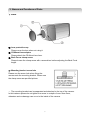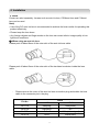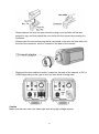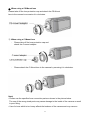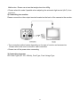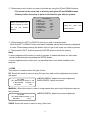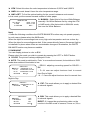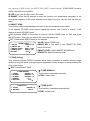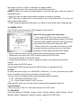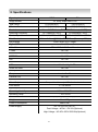
1
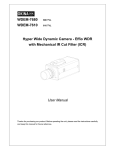
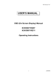
High Resolution / Day&Night
COLOR BOX CAMERA
사용 설명서 MANUAL
용 서
650 TVL
The lightning flash with an arrowhead symbol, within an equilateral
triangle is intended to alert the user to the presence of uninsulated
dangerous voltage within the product's enclosure that may be of
sufficient magnitude to constitute a risk of electric shock to persons.
The exclamation point within an equilateral triangle is intended to alert
the user to the presence of important operating and maintenance
(servicing) instructions in the literature accompanying the appliance.
INFORMATION - This equipment has been tested and found to comply with limits for a
Class A digital device, pursuant to part 15 of the FCC Rules.
These limits are designed to provide reasonable protection against harmful interference
when the equipment is operated in a commercial environment.
This equipment generates, uses, and can radiate radio frequency energy and, if not
installed and used in accordance with the instruction manual, may cause
harmful interference to radio communications.
Operation of this equipment in a residential area is likely to cause harmful interference in
which case the user will be required to correct the interference at his own experience.
WARNING - Changes or modifications not expressly approved by the
manufacturer could void the user’s authority to operate the equipment.
CAUTION : To prevent electric shock and risk of fire hazards:
Do NOT use power sources other than that specified.
Do NOT expose this appliance to rain or moisture.
This installation should be made by a qualified service person and should conform
to all local codes
2
■ Warning
The camera needs periodic inspection.
Contact an authorized technician for inspection.
Stop using your camera when you find a malfunction.
If you use your camera around smoke or unusual heat for a long time,
fire may be caused.
Do not Install the camera on a surface that can not support it.
Unless the surface is suitable, it could cause falling or other hazards.
Do not hold plug with wet hands.
It could cause an electric shock.
Do not disassemble the camera.
It may result in fire, electric shock or other hazards.
Do not use the camera close to a gas or oil leak.
It may result in fire or other hazards.
3
■ Contents
1.Features
---------------------------------
6
2. Components
---------------------------------
7
3. Names and functions of parts
---------------------------------
8
4. Installation
---------------------------------
10
5. Setup Menu Operation
---------------------------------
14
6. Troubleshooting
---------------------------------
24
7. Specifications
---------------------------------
25
4
1. Features
☺Ultra High Resolution 650 TV Lines
Clear image quality has been achieved by employing a double-speed SONY CCD with
410,000(effective) pixels, which provides a horizontal resolution of 650 TV lines.
☺Excellent Sensitivity
The built-in high sensitivity COLOR CCD enable a clear image even in 0.1Lux (color),
0.00001Lux (Sens-Up) or lower illumination.
☺Electrical Day & Night (True Day & Night: Optional)
The camera identifies whether it is day or night and automatically switches to the
appropriate mode, depending on its environment. By day, the camera switches to color
mode in order to maintain optimal color. At night, it switches to B/W mode so as to obtain
better picture definition.
☺F-DNR(Defog)
This camera supports Defog function which does a process of clearing blurred image
caused by fog and snow by analyzing the brightness of input image and compensating
Color of the image.
☺Coaxial cable communication
This is a remote control function that uses the coaxial cable with the control signal. And
this helps you control the camera’s condition what you want without additional cabling in
installation or repair.
☺Motion Detection
Since the camera detects motion and generates signals without any additional external
sensors, you can monitor activity more efficiently by connecting the camera to an alarm
device.
☺White Defect restoration
When the camera has white defect in the CCD with ages, User can restore it.
☺D-WDR
Built-in Digital WDR
☺SMART 3D-DNR
The high performance New DSP chip dramatically reduces the gain noise in digital image
processing, producing clear, sharp images in low lighting environment. Especially It will be
operate 3D DNR mode before happening motion, but if there is motion, it will be change
smart 3D DNR mode.
☺Controlled by OSD Menu
The camera can be controlled by selecting text displayed on the monitor screen.
☺Additional Functions
HSBLC, DIS, FREEZE, Mirror(H,V-FLIP,ROTATE), D-ZOOM, Negative Image, Sharpness,
Privacy functions.
5
2. Components
-------------
1)
COLOR CAMERA
2)
AUTO IRIS LENS CONNECTION ------------PLUG
3)
C-MOUNT ADAPTOR
-------------
4)
L-WRENCH
-------------
5)
MANUAL
-------------
6
3. Names and Functions of Parts
1) Front
① Lens protection cap
Please cover the lens when not using it.
② CS-Mount lens adaptor
Please attach the CS-Mount lens here.
③ Back Focus clamp screw
Please loosen the clamp screw with a screwdriver before adjusting the Back Focal
length.
☞ Mounting bracket screw hole
Please use the screw hole when fixing the
camera onto the mounting bracket. Please use
the clamp screw as specified picture.
☞ The mounting bracket can be separated and attached to the top of the camera.
In this instance please do not tighten the screw to a depth of more than 5mm,
otherwise serious damage can occur to the inside of the camera.
7
2) Back
① Auto iris lens connector
This is the connection terminal for the auto iris lens.
② Video output terminal
Sends video signals and connects to the video input terminal of the monitor.
③ Power lamp
Lights up when the correct power is supplied to the camera.
④ Setting button
SETUP button : Used for the menu display. This button can be used to confirm
settings after changing the value of the selected function or current conditions.
UP & DOWN buttons : Used for selecting items by moving the cursor up or down on
the menu screen.
LEFT & RIGHT buttons : Used when changing item values, by moving the cursor to
the left or right on the menu screen.
⑤ Power input terminal
Connects to the power appropriate to each power requirement.
⑥ Auto Iris Switch
Video or DC
☞ Make sure that user can’t use video type lens using high voltage camera.
8
4. Installation
1) Lens
Lenses are sold separately. Lenses such as auto iris lens, CS-Mount lens and C-Mount
lens can be used.
Note)
• Use of the DC auto iris lens is recommended to achieve the best results for operating this
product effectively.
• Please keep the lens clean.
• Any foreign objects and finger marks on the lens can cause inferior image quality in low
light level conditions.
① When using an auto iris lens
Please peel off about 8mm of the outer skin of the auto iris lens cable.
Please peel off about 2mm of the outer skin of the insulated conductor inside the lens
cable
-
Please remove the cover of the auto iris lens connection plug and solder the lens
cable to the connector pin in the plug.
Pin No.
LENS
DC
VIDEO
No.1 Pin
Damping-
Red(power)
No.2 Pin
Damping+
NC
No.3 Pin
Drive+
White(video signal)
No.4 Pin
Drive-
Black(GND)
9
-
-
Please replace the auto iris lens connection plug cover and take off the lens
protection cap, and then attach the auto iris lens to the camera by screwing it in
clockwise.
Please insert the connection plug that is connected to the auto iris lens cable into
the auto lens connector, which is located on the back of the camera
-
Please set the lens selection switch, located on the back of the camera, to DC or
VIDEO depending on the type of auto iris lens which is being used.
Caution
Make sure that user can’t use video type lens using high voltage camera.
10
② When using a CS-Mount lens
Please take off the lens protection cap and attach the CS-Mount
lens to the camera by screwing it in clockwise.
③ When using a C-Mount lens
- Please take off the lens protection cap and
attach the C-mount adaptor.
-
Please attach the C-Mount lens to the camera by screwing it in clockwise.
Note)
• Please use the specified lens connection parts as shown in the picture below.
The use of the wrong sized parts may cause damage to the inside of the camera or result
in poor fitting.
• Use of a lens which is too heavy affects the balance of the camera and may cause a
11
Malfunction. Please use a lens that weighs less than 450g.
• Please select Av mode if possible when adjusting the automatic light control (ALC) of an
auto lens.
2) Connecting to a monitor
Please connect the video output terminal located on the back of the camera to the monitor.
• The connection method varies depending on the type of monitor and accessories.
Please refer to the user's manual for each instrument.
• Please turn off the power when connecting.
3) Connecting to power
DC Power Type (DC 12V, 500mA), Dual Type, Free Voltage Type
12
5. Setup Menu Operation
• Menu
Structure
LENS
DC / VIDEO / MANUAL
EXPOSURE
SHUTTER
AUTO / FLK / MANUAL / 1/60
AGC
LOW / MIDDLE / HIGH / OFF
SENSE-UP
AUTO / OFF
RETURN
BACK LIGHT
OFF / DWDR / BLC / HSBLC
WHITE BAL
ATW / AWB / AWC-SET / MANUAL
DAY & NIGHT
AUTO / EXT / NIGHT / COLOR
SMART 3DNR
OFF / ON
F-DNR
OFF / MANUAL / AUTO
FUNCTION
MOTION
OFF / ON
PRIVACY
OFF / ON
D-EFFECT
D-ZOOM / SAMART ZOOM / DIS / PIP /
FREEZE / MIRROR / NEG. IMAGE
IMAGE ADJ
SHARPNESS / MONITOR / LENS SHADING
/ DEFECT
COMM ADJ
CAM TITLE
SYNC
LANGUAGE
RETURN
EXIT
SAVE / CANCEL / RESET
• Settings
① Please press the SETUP button Settings can now be made. The SETUP menu is
displayed on the monitor.
13
② Please select any function you wish to activate by using the UP and DOWN buttons.
- The arrow can be moved up or down by using the UP and DOWN buttons.
- Please position the arrow to point to the function you wish to operate.
Select any function you
wish to operate by using
the
UP
and
DOWN
buttons.
MAIN MENU
1. LENS
DC↙
2. EXPOSURE
↙
3. BACK LIGHT
OFF
4. WHITE BAL
ATW
5. DAY NIGHT
AUTO
6. SMART 3DNR
OFF
7. F-DNR
OFF
8. FUNCTION
↙
9. EXIT
↙
Modes can be changed
using
the
LEFT
and
RIGHT buttons.
③ Please press the LEFT or RIGHT button if you wish to change mode.
When the LEFT or RIGHT button is pressed, available values and modes are displayed
in order. Please keep pressing the button until you get to the mode you wish to operate.
④ Please select 'EXIT' and then press the SETUP button to finish the setting.
Note)
• If arrow appears at the mode you wish to operate, it means that there is a sub-menu
which can be selected by pressing the SETUP button.
• If arrow appears at the mode item, it means that there is no mode available to be
selected.
1. LENS
This function is used to select the type of lens.
DC: Select this mode in case of using DC type lens and control brightness value at the
sub-menu.
▶BRIGHTNESS: Adjust the screen brightness
DC LENS
▶IRIS SPEED: Adjust iris speed
▶1. BRIGHTNESS IIIIIIIIIII 1~100
2. IRIS SPEED
RETURN
IIIIIIIIIIIII 1~5
RET↙
MANUAL: Select this mode in case of using manual lens and control brightness value at
the submenu.
DC LENS
▶1. BRIGHTNESS IIIIIIIIIII 1~100
RETURN
RET↙
▶BRIGHTNESS: Adjust the screen brightness
VIDEO: Select this mode in case of using Video lens.
14
2. EXPOSURE
This function is used to adjust EXPOSURE
EXPOSURE
▶SHUTTER
AUTO
AGC
HIGH
SENSE-UP
ON↙
RETURN
RET↙
SHUTTER: Select shutter speed.
The default value is AUTO.
▶ AUTO, FLK, MANUAL, 1/50
AGC (Auto Gain Control)
▶ LOW / MIDDLE / HIGH
SENS-UP (Digital slow shutter)
▶ OFF / AUTO (x2~x256)
3. BACK LIGHT
This function is used to view a picture more clearly under back light condition.
▶ BLC
Enable a user to directly select a desired area from a picture, and to view the area more
clearly.
BLC
▶1. VALUE
2. AREA
3. DEFAULT
4. RETURN
MIDDLE
SINGLE↙
↙
RET↙
VALUE: Select BLC value.
• LOW / MIDDLE /HIGH
AREA: Select area and then adjust size and
position of the area.
DEFAULT: Initialize all data you set.
▶ DWDR
When there are both bright and dark areas at the same time, this mode makes both areas
distinctive.
DWDR
▶1. LOW LEVEL IIIIIIIIII 0~15
2. HIGH LEVEL IIIIIIIIIII 0~15
3. RETURN
RET↙
LOW LEVEL: Set lower level (0~15)
HIGH LEVEL: Set High level (0~15)
▶ HSBLC
HSBLC
▶1. GAIN
IIIIIIIIIII 1~100
2. MODE
NIGHT ONLY
3. MASK LEVEL IIIIIIIIII 1~100
4. DEFAULT
↙
5. M. SKIP AREA
OFF
6. RETURN
RET↙
GAIN: select gain value.
MODE: select between night only mode and all day
mode
MASK LEVEL: select mask level.
DEFAULT: Initialize all data you set.
M.SKIP AREA: set exception area where HSBL
MASK doesn’t work.
4. WHITE BALANCE
The screen color can be adjusted by using the WHITE BALANCE function.
15
▶ ATW: Select this when the color temperature is between 2,000°K and 9,000°K
▶ AWB: this mode doesn’t have the color temperature range.
▶ AWC->SET: To find the optimal setting for the current luminance environment
in this mode, put the camera towards a sheet of white paper.
▶ MANUAL: Select this to fine-tune White Balance
MANUAL WD
manually. Set White Balance first by using the ATW
▶1. BLUE
IIIIIIIII 1~100
2. RED
IIIIIIIII 1~100
or AWB mode. After that switch to MANUAL mode,
3. RETURN
RET↙
fine-tune the White Balance.
Note)
• Under the following conditions the WHITE BALANCE function may not operate properly.
In such cases, please select the AWB mode.
When the object’s surroundings have a very high color temperature such as a clear sky.
When the object’s surroundings are dark, If the camera directly faces a fluorescent light or
is installed in a place where there are considerable changes in illumination, the WHITE
BALANCE function may become unstable.
5. DAY&NIGHT
You can display pictures in color or B/W.
Please select the mode you wish to operate by pressing the LEFT or RIGHT button.
▶ COLOR: The picture is always displayed in color.
▶ AUTO: The mode is switched to ‘Color’ in a normal environment, but switches to ‘B/W’
mode when ambient illumination is low.
- DELAY: adjusting converting speed for COLOR ↔
D&N AUTO
▶DELAY IIIIIIIIIIIIIIIIII 0~15
D→N
IIIIIIIIIIIIIIIIIII 16~249
N←D
IIIIIIIIIIIIIIIIIII 1~233
RETURN
RET↙
BW
- D→N: user can adjust luminous level to convert
from Day to Night.
- N→D: user can adjust luminous level to convert from
Night to Day.
D&N EXT
▶DELAY IIIIIIIIIIIIIIIIIIIII 0~15
RETURN
RET↙
D&N NIGHT
▶BURST
OFF
IR SMART
OFF
IR LED
ON
RETURN
RET↙
▶ EXT: This mode allows you to apply a desired filter
to external signals.
▶ B/W: This mode allows you to apply a desired filter
to external signals.
BURST: If it cannot be synchronizing video on the
monitor in the BW mode of camera, it turns on.(When
16
the camera in B/W mode, the WHITE BALANCE is deactivated.) If DAY NIGHT mode is
AUTO, the AGC is fixed HIGH.
IR LED: if you use IR LED, select On mode.
IR SMART: When the IR camera is used, this function can suppresses saturation of the
picture that happens in the short distance from object and you can set area up that you
want.
6. SMART 3DNR
This function reduces the background noise in a low luminance environment.
It will operate 3D DNR mode before happening motion, but if there is motion, it will
change to smart 3D DNR mode.
▶ON: Activates 3DNR so that noise is reduced. Set the 3DNR mode to ‘'ON’' and press
the SET button. Then you can adjust the noise reduction level.
▶OFF: Deactivates 3DNR. Noise is not reduced.
SMART 3DNR
1. VALUE
IIIIIIIIII 0~200
2. SMART NR
ON
3. SMART LEVEL IIIIIIII 0~200
4. SENSITIVITY
IIIIIIIII 0~100
RETURN
RET↙
VALUE: adjust 3 DNR level
SMART NR: if you want to use SMART 3D DNR,
select ON mode.
SMART LEVEL: adjust SMART 3D DNR level
SENSIVITY: adjust sensitivity level
7. F-DNR (Defog)
This camera supports DEFOG function which does a process of clearing blurred image
caused by fog and snow by analyzing the brightness of input image and compensating the
color of the image
▶ OFF: Deactivates F-DNR.
F-DNR MANUAL
1. LEVEL
IIIIIIIIIIIII1~ 5
2. DUMMY
IIIIIIIIIIIII1~ 10
3. DUMMY
IIIIIIIIIIIII1~ 10
4 GAMMA
0.1~1
5. RETURN
RET↙
F-DNR AUTO
1. LEVEL
IIIIIIIIIIIII 1~5
2. RETURN
RET↙
▶ F-DNR MANUAL
This function is operated manually
LEVEL: Select level
▶ F-DNR AUTO
This function is operated automatically.
LEVEL: select level
17
F-DNR OFF
F-DNR ON
8. FUNCTION
Select any function you
wish to operate by using
the
UP
and
DOWN
buttons.
FUNCTION
1. MOTION
2. PRIVACY
3. D-EFFECT
4. IMAGE ADJ
5. CAMERA TITLE
6. SYNC
7. LANGUAGE
8. RETURN
Modes can be changed
OFF
OFF
↙
↙
OFF
INT
ENGLISH
using
the
LEFT
and
RIGHT buttons.
1) MOTION
Motion detection function
allows more effective
observation. When any movement is detected, signal is generated
▶ ON: If ‘MOTION’ function is active, character of person is flickering on right above
position when motion is detected on selected area.
MOTION
1. AREA
1
2. AREA DISPLAY
ON↙
3. VALUE
IIIIIIIIIII 0~100
4. MOTION VIEW
ON
5. RETURN
AREA: Select the programmed area that can be set up
to 4 areas.
AREA DISPLAY: Turn on and off the programmed
motion area.
VALUE: Adjust motion sensitivity of the programmed
motion area.
MOTION VIEW: Turn on and off the display when
motion detected.
▶ OFF: Cancel Motion detection function.
2) PRIVACY (POLYGON)
You may conceal specific area on the screen with this ‘PRIVACY’ function.
18
PRIVACY
1. AREA
1
2. AREA DISPLAY
ON↙
3. COLOR
IIIIIIIIIII 0~15
4. TRANSPAR
IIIIIIIIIII 0~3
5. RETURN
AREA: Select the programmed privacy area (Area 1~8)
AREA DISPLAY: Turn on and off the programmed
privacy masking.
Set position and area size for privacy masking using
arrow
COLOR: Setup color of the programmed motion area
mask (1-15 color)
TRANSPAR: select color transparency.
3) D-EFFECT
D-EFFECT
1. D-ZOOM
2. SMART ZOOM
3. DIS
4. PIP
5. FREEZE
6. MIRROR
7. NEG. IMAGE
8. RETURN
ON↙
ON↙
OFF
OFF
OFF
OFF
OFF
D-ZOOM: You can use a digital zoom (256x).
- PAN: Moving zoom-in picture to left-right
- TILT: Moving zoom-in picture to up-down
* It doesn’t work for PAN. TILT when the D-ZOOM is
on x1.0.
SMART ZOOM: When motion is detected, SMART
ZOOM will be operated to preset point automatically.
DIS(Digital image stabilizer):Protect against camera shake
PIP(Picture in picture): When using digital zoom, you can view wide scene without digital
zoom on the monitor.
FREEZE: You can view still or moving pictures.
MIRROR: You can flip the picture
- MIRROR: Horizontal reverse pictures on the monitor.
- V-FLIP: Vertical reverse pictures on the monitor.
- ROTATE: diagonal reverse pictures on the monitor (180° rotation)
NEG. IMAGE: Switching to negative color.
4) IMAGE ADJ
SHARPNESS: Adjust sharpness of the video picture
IMAGE ADJ
MONITOR: Select the kind of the monitor (LCD / CRT)
1. SHARPNESS
IIIIIIIII 0~31
OSD COLOR: User can select OSD color
2. MONITOR
CRT↙
3. LENS SHADING
ON↙
▶ CRT: Select this menu when using a CRT monitor.
4. DEFECT
5. RETURN
↙
- PED LEVEL: Adjust PED level.
- COLOR GAIN: Adjust COLOR GAIN
▶ LCD: Select this menu when using a LCD monitor
- GAMMA: Adjust GAMMA level
- PED LEVEL: Adjust PED level.
- COLOR GAIN: Adjust COLOR GAIN
LENS SHADING: When setting the zoom to maximum and Lens angle of view are
19
saturated on screen, set ON to make the Lens edge invisible.
It might happen only if fluorescent light is shined fully on screen.
DEFECT: When the camera has white defect in the CCD with ages, user can restore it
using OSD menu.
- Sense-up: User can adjust white defect according to luminous condition.
- DIFF: User has to select level(1~4) according to size of the white defect. If it is big, you
have to select high number
- START: Before pressing the Start menu, you have to cover camera lens using lens cap
5) CAMERA TITLE
If the TITLE is input, the camera TITLE appears on the monitor.
Select an ID from A,B~Y,Z, 0,1~8,9.
Note) If the wrong name has been input.....
• If you press the SETUP button after moving the
cursor to CLR, all the letters will be erased. If you want
to correct a letter, please move the cursor to the arrow
at the bottom left of the screen and press 'SET'.
• Please position the cursor above the letter you wish
to correct, and then move the cursor on to the letter
you wish to choose and press the SETUP button.
• When a name has been chosen, please select a position for the name display.
▪ Please move the cursor onto 'POS' and then press the SETUP button.
▪ The name will appear at the top left corner.
▪ Please find the position you wish to display the name in by using the 4 directional
buttons,
and then press the SETUP button.
▪Please select 'END' and then press the SETUP button to complete ID input.
6) SYNC
In areas where the supply is at 60Hz/NTSC (50Hz/PAL), you can synchronize the output
phase of multiple cameras using the power synchronization
function (Line-Lock) without using a synchronization signal generator.
• INT : Internal Synchronization Type
• L/L : Power Synchronization Type, Line-lock
Press the SET button and you can select a desired phase between 0 and 359.
synchronization.
• When the power is DC 12V, the menu is fixed to the ‘INT’ mode.
7) LANGUAGE
It can be switched to English, Korean, Polish, Turkish, Hebrew, Arab, Russian, French,
Spanish, Italian, Portuguese, German, chinese, Japanese on OSD menu.
20
7. Troubleshooting
If there are problems in operation, please refer to the items below. If the problem persists,
please contact the agent you purchased this product from.
Problems
Nothing appears on the screen.
Troubleshooting
• Please check the power connection.
• Please check the video signal line connection.
• Please check and make sure that the auto lens switch is
set to DC (VIDEO) when using a VIDEO(DC) lens.
The video image is not clear.
• Please check if the lens is clean.
Please clean the lens with a clean cloth or brush.
• Please adjust the contrast feature of the monitor.
• Please readjust the back focus of the camera.
The screen is dark.
• Please adjust the contrast feature of the monitor.
• If you have an intermediate device, set the 75 / Hi-z
properly, and check the terminals.
• Please check if an auto iris lens is being used and adjust
the brightness level.
There is a problem with the
camera operation.
• Please check if an appropriate power source to the
camera complies with the manufacturer's
standard requirement, or if the voltage keeps changing.
The MOTION DETECTION
function is not working.
• Please check if 'MOTION DETECTION' mode is turned
on.
• Please check if the MD LEVEL is too low.
• Please check the setting of the MD AREA.
Colors are not quite right.
• Please check the 'WHITE BAL' setting
The screen is flickering.
• Please check if the camera is facing directly into sunlight
or fluorescent light.
• Please check if an auto iris lens is being used.
• Please check the connection of the lens connector cable.
COLOR mode is not working.
• Please check if the AGC menu is set to the OFF
position.
SENS-UP function is not
• Please check if the AGC menu is set to the OFF
working.
position.
• Please check if the SHUTTER menu is set to
MANUAL mode.
21
8. Specifications
Signal system
NTSC
Image Sensor
PAL
1/3” Sony Super HAD CCD
Total Pixels
811(H)X508(V)
795(H)X596(V)
Effective Pixels
768(H)X494(V)
752(H)X582(V)
Resolution
Scanning Frequency
Color : 650 TV Lines, B/W : 750 TV Lines (with ICR)
15.734KHz(H), 60(V)
15.625KHz(H), 50(V)
Shutter Speed
1/60~1/100,000 sec/ FLK
1/50~1/100,000 sec/ FLK
Min. Illumination
Color : 0.1Lux @ F 1.2,
0.00001Lux (Sense-up 256x)
Day & Night
Color / Auto / EXT / Night
Digital WDR
On / Off
White Balance
ATW / AWB / AWC-Set / Manual
F-DNR
On / Off
Coaxial Communication
Available
DEFECT
On / Off
DIS
On / Off
BLC
BLC / HSBLC
AGC
Low / Middle / High / Off
Smart 3D-DNR
On / Off
Privacy / Motion Zone
8 Zones / 4 Zones
Sharpness
Level : 0 ~ 31
Camera Title
On / Off
S/N Ratio
More than 50dB
Video Output
Composite video output 75 ohm terminated
Lens Mount
C / CS Mount
Sync. System
Internal
Operating Humidity
30 % ~ 90 % RH
Operating Temp.
- 10°C to 50°
Dimension
61(W) X 55(H) X 104.7(D)mm
Weight
About 420g
Power Consumption
Power Supply
Max 2.5W
DC 12 V(10.2V~14.5 V)
Dual Voltage : AC24V / DC12V(Optional)
High Voltage : AC 90V~250V 50/60Hz(Optional)
22