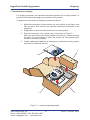
1
HygroPort Portable Hygrometer User’s Manual KAHN INSTRUMENTS, INC 885 Wells Road , Wethersfield, CT 06109 Phone: 860-529-8643 Fax: 860-529-1895 E-mail: [email protected] www.kahn.com Inside front cover (blank) HygroPort Portable Hygrometer HygroPort Portable Hygrometer Kahn Instruments, Inc. Phone: 860-529-8643 Fax: 860-529-1895 Email: [email protected] www.kahn.com i Issue 2 February 2014 HygroPort Portable Hygrometer SAFETY The manufacturer has designed this product to be entirely safe when operated correctly. 1. Please pay careful attention to the Safety Instructions outlined on this page and elsewhere in this manual. They have been designed to protect the user from personal injury and the equipment from damage. 2. Please observe the installation advice and any operational limitations given in this manual. 3. This equipment must only be used for the purpose for which it was designed. Electrical safety The instrument is designed to be completely safe when used with options and accessories supplied by the manufacturer for use with the instrument. The instrument is powered by an internally mounted rechargeable battery. The input power supply voltage limits for the battery charger supplied with the instrument are 100V ac to 240V ac, 47Hz to 63Hz. Refer to Appendix 1-Specification. Caution Only the battery charger unit supplied with the instrument should be used. Pressure safety DO NOT permit pressures greater than the safe working pressure to be applied to the instrument. The specified safe working pressure (SWP) for this instrument is 5000 PSIG. Refer to Appendix 1- Specification. Toxic materials The use of hazardous materials in the construction of this instrument has been minimized. During normal operation, it is not possible for the user to come into contact with any hazardous substance which might be employed in the construction of the instrument. However, care should be used during maintenance and the disposal of certain parts. Repair and maintenance The instrument must be maintained by the manufacturer. Calibration The recommended calibration interval for this instrument is 12 months. The instrument should be returned to Kahn Instruments, Inc. for re-calibration. Safety conformity This product carries the CE mark and meets the requirements of all the relevant U.S. and European safety directives. Refer to Appendix 1- Specification for details. Issue 2 February 2014 ii Kahn Instruments, Inc. 885 Wells Road Wethersfield, CT 06109 FCC Declaration of Conformitv. HygroPort, Portable Dewpoint Hygrometer. This Device complies with FCC Rules Part 15 Subpart B Unintentional Radiators Class B digital devices. Operation is subject to the following conditions: 1) This device may not cause harmful interference 2l This device must accept any interference received, including interference that may cause undesired operation. Note: This product has been tested and found to comply with the limits or Class B digital devices, pursuant to Part 15 of the FCC rules. This product generates, uses and can radiate radio frequency energy and, if not installed and used in accordance with the instructions, ffidy cause harmful interference to radio communications. However, there is no guarantee that interference will not in a particular installation. lf this product does cause harmful interference to radio reception, which may be determined by turning the product on & off, the user is encouraged to try to correct the interference by one or more of the following measures: r Reorient or relocate the receiving antenna, e Increase the separation between the product and receiver, I Cgnnect the equipment into an outlet on a circuit different from that to which the receiver is connected o Consult the dealer or an experienced radio/TV technician for help. This product must be operated as per the operating instructions provided. Do not make any alterations or modifications to the product. Any unauthorised alterations or modifications made to this product may require you to stop operating the product. Canadian Radio Interference Regulations. This Class B digital product complies with Canadian ICES-003, CISPR 22 :1997. Rdglement canadien sur les interf6rences radio. Ce produit num6rique de classe B est conforme i la norme NM8-003, CISPR 22: 1997. Signed for, and on behalf of, KAHN INSTRUMENTS,INC. 85 Wells Road Wethersfield, CT 06109 Phone: (860) 529-8643 (860) 529-1895 (860) 529-1895 E-mail: [email protected] David A. Kahn, Vice President lssue date: 05/201,1 HygroPort Portable Hygrometer We, Michell Instruments Limited 48 Lancaster Way Business Park, Ely Cambridgeshire CB6 3NW UK declare under our sole responsibility that the product HygroPort Portable Hygrometer to which this declaration relates is in conformity with the following standards or other normative document(s) EN61326-1:2006 Electrical equipment for measurement, control and laboratory use EMC requirements Group1, Class B equipment - (emissions section only) EN61326-1:2006 Electrical equipment for measurement, control and laboratory use EMC requirements Inustrial location immunitty - (immunity section only) E301 489-1 Electromagnetic compatibility and Radio spectrum Matters (ERM); V1.6.1 Electromagnetic compatibility(EMC) standard for radio equipment Class B and services; Part1: Common technical requirements CFR 47:2007 Code of Federal Regulations:Pt 15 Sub-part B - Radio Freqency Devices Class A Unintentional Radiators Date of Issue: June 2009 Kahn Instruments, Inc. Phone: 860-529-8643 Fax: 860-529-1895 Email: [email protected] www.kahn.com iii Issue 2 February 2014 HygroPort Portable Hygrometer ABBREVIATIONS Note: Abbreviations are not pluralized, they remain the same in both the singular and plural. AC atm bar Bar a Bar g °C °F K COM contd DC ENT FS ft Hz in in2 N/C kg kΩ lb LSD m mA max min mm MPa mV MΩ No. Pa PIN ppm(v) rdg %rdg RS 232 Rx SWP sec temp Tx V Ω Issue 2 February 2014 alternating current pressure unit (atmosphere) pressure unit (=100 kP or 0.987 atm) bar absolute bar gauge degrees Celsius degrees Fahrenheit Kelvin (absolute temperature) common continued direct current enter (select) full-scale foot (feet) Hertz inch(es) square inch(es) not connected (no connection) kilogram(s) kilohm(s) pound least significant digit metre(s) milli Ampere maximum minute(s) millimetre(s) megapascal (Pascals x106) milli Volt(s) megohm(s) number Pascal(s) personal identification number parts per million (by volume) reading percentage of reading serial data transmission standard receive safe working pressure second(s) temperature transmit Volts Ohms iv Kahn Instruments, Inc. 885 Wells Road Wethersfield, CT 06109 HygroPort Portable Hygrometer WARNINGS The following general warnings listed below are applicable to this instrument. They are repeated in the text in the appropriate locations. ! Where this hazard warning symbol appears in the following sections, it is used to indicate areas where potentially hazardous operations need to be carried out. Where this hazard warning symbol appears in the following sections it is used to indicate areas of potential risk of electric shock. DANGER Electric Shock Risk Where this hazard warning symbol appears in the following sections it is used to highlight where care needs to be taken to prevent static discharge from damaging electrostatically sensitive items or components. Kahn Instruments, Inc. Phone: 860-529-8643 Fax: 860-529-1895 Email: [email protected] www.kahn.com v Issue 2 February 2014 HygroPort Portable Hygrometer Contents SAFETY ............................................................................................................................... ii EC Declaration of Compliance ................................................................................... iii Abbreviations............................................................................................................... iv GENERAL WARNINGS . ............................................................................................ v Contents...................................................................................................................... vi 1 Introduction . ............................................................................................................... 1 2 Description.................................................................................................................. 3 2.1 Controls and indicators............................................................................................. 4 2.2 Function keys........................................................................................................... 5 2.3 Instrument display.................................................................................................... 7 2.4 Instrument start-up................................................................................................... 8 2.4.1 Display units .................................................................................................10 2.6 Overall Menu Structure (Figure 2.7)........................................................................12 2.6.1 General settings (Figure 2.8)..............................................................................14 2.6.2 Logging (Figure 2.9)...........................................................................................15 2.6.3 Bluetooth settings (Figure 2.10).........................................................................16 2.6.4 External transmitter selection (Figure 2.11)........................................................17 2.6.5 Real time clock settings (Figure 2.12)................................................................18 2.6.6 Human Machine Interface (HMI) settings (Figure 2.13).....................................19 2.6.7 Calibration (Figure 2.14).....................................................................................20 2.6.9 Chart options (Figure 2.15) ...............................................................................21 3 Installation..................................................................................................................23 3.1 Safety......................................................................................................................23 3.2 Unpacking the instrument........................................................................................23 3.3 HygroPort accessories............................................................................................24 3.4 Operational requirements........................................................................................26 3.4.1 Environmental requirements..............................................................................26 3.4.2 Charger electrical requirements.........................................................................26 3.5 Instrument gas connections....................................................................................26 3.5.1 Fit gas inlet/outlet adaptors (Figure 3.4).............................................................27 3.6 Connect external transmitters.................................................................................28 3.6.1 Set-up external pressure transmitter parameters...............................................28 3.6.2 Set-up external temperature parameters...........................................................29 3.6.3 Set-up external dewpoint (Easidew) parameters...............................................29 3.7 Connect battery charger (Figure 3.9)......................................................................30 Contents (Contd.) Issue 2 February 2014 vi Kahn Instruments, Inc. 885 Wells Road Wethersfield, CT 06109 HygroPort Portable Hygrometer 4 Operation....................................................................................................................31 4.1 Preparation for operation.........................................................................................31 4.2 General operational information..............................................................................31 4.3 Operating cycle.......................................................................................................34 4.3.1 Response times..................................................................................................34 4.4 First time operation..................................................................................................36 4.5 Graphics display......................................................................................................37 4.5.1 Display datalog file list........................................................................................37 4.5.2 Display current datalog file ................................................................................38 4.6 Logging....................................................................................................................38 4.7 Bluetooth mode.......................................................................................................39 4.7.1 Bluetooth pairing procedure...............................................................................39 4.8 Select external transmitter........................................................................................41 4.9 Interchange primary and secondary displays ..........................................................42 5 5.1 Good measurement practice....................................................................................43 General operational guidelines...............................................................................43 6 Calibration................................................................................................................45 6.1 Traceability.............................................................................................................45 6.2 HygroPort adjustment procedure...........................................................................46 6.3 Calibration correction method................................................................................47 6.3.1 HygroPort calibration correction.........................................................................47 6.3.2 Easidew Offset Adjustment.................................................................................49 6.3.3 Easidew One Point Adjustment..........................................................................50 7 Shipping...................................................................................................................51 List of Tables 2.1 2.2 2.3 2.4 2.5 2.6 2.7 2.8 HygroPort – Controls and indicators...................................................................... 4 Instrument display.................................................................................................... 7 General settings..................................................................................................... 14 Logging parameter set-up...................................................................................... 15 Bluetooth settings................................................................................................... 16 External transmitter selection................................................................................. 17 Real time clock settings.......................................................................................... 18 Human Machine Interface (HMI) settings............................................................... 19 3.1 Adaptor fittings........................................................................................................ 26 4.1 4.2 HygroPort default parameters................................................................................ 32 HygroPort sensor response times.......................................................................... 35 6.1 Example of calibration run readings....................................................................... 46 Kahn Instruments, Inc. Phone: 860-529-8643 Fax: 860-529-1895 Email: [email protected] www.kahn.com vii Issue 2 February 2014 HygroPort Portable Hygrometer List of Illustrations 1.1 HygroPort Portable Hygrometer............................................................................ 2 2.1 User connections, controls and indicators.............................................................. 3 2.2 Function keys.......................................................................................................... 5 2.3 Instrument display................................................................................................... 7 2.4 Instrument start-up sequence ................................................................................ 9 2.5 Change display units............................................................................................ 10 2.6 Passcode entry......................................................................................................11 2.7 HygroPort Menu structure..................................................................................... 13 2.8 General settings menu.......................................................................................... 14 2.9 Set-up logging menu............................................................................................. 15 2.10 Bluetooth settings................................................................................................. 16 2.11 Select external transmitter ................................................................................... 17 2.12 Real time clock settings........................................................................................ 18 2.13 Display settings..................................................................................................... 19 2.14 Calibration............................................................................................................. 20 2.15 Info screen............................................................................................................ 20 2.16 Typical chart plot . ................................................................................................ 21 2.17 Reset chart........................................................................................................... 21 2.18 Datalog file list...................................................................................................... 21 2.19 Current datalog file............................................................................................... 22 3.1 Packing method.................................................................................................... 23 3.2 Gas port adaptors................................................................................................. 24 3.3 Accessories.......................................................................................................... 25 3.4 Examples of gas coupling types........................................................................... 27 3.5 External transmitter connection............................................................................ 28 3.6 Typical external pressure display.......................................................................... 28 3.7 Typical external pressure display.......................................................................... 29 3.8 Typical external dewpoint display......................................................................... 29 3.9 Connect battery charger ...................................................................................... 30 4.1 HygroPort menu structure..................................................................................... 33 4.2 HygroPort operating cycle.................................................................................... 34 4.3 Initialization start-up.............................................................................................. 36 4.4 Typical screen start-up display............................................................................. 36 4.5 Typical chart display............................................................................................. 37 4.6 Datalog file list...................................................................................................... 37 4.7 Typical current log file display............................................................................... 38 4.8 Logging set-up menu............................................................................................ 38 4.9 Bluetooth set-up menu.......................................................................................... 39 4.10 Typical Bluetooth pairing sequence...................................................................... 40 4.11 External; set-up menu........................................................................................... 41 4.12 Human Machine Interface (HMI) set-up menu...................................................... 42 4.13 Typical external display as primary display screen............................................... 42 Issue 2 February 2014 viii Kahn Instruments, Inc. 885 Wells Road Wethersfield, CT 06109 HygroPort Portable Hygrometer List of Illustrations(Contd.) 6.2 6.3 6.4 6.5 6.6 Calibration screen................................................................................................. 47 HygroPort calibration correction screen................................................................ 47 Edit HygroPort look-up table . .............................................................................. 48 Easidew offset adjustment.................................................................................... 49 Easidew single point adjustment.......................................................................... 50 7.1 Instrument packing details .............................................................................. 51 A3.1 Current datalog file display (Appendix 2).............................................................. 61 A3.2 HygroPort status register (Appendix 2)................................................................. 61 A3.3 HygroPort status register (Hex 28)....................................................................... 61 List of Appendices Appendix 1 Specification.................................................................................................. 53 Appendix 2 Datalog status display................................................................................... 56 Kahn Instruments, Inc. Phone: 860-529-8643 Fax: 860-529-1895 Email: [email protected] www.kahn.com ix Issue 2 February 2014 HygroPort Portable Hygrometer 1 Introduction Introduction The HygroPort Portable Hygrometer is a portable instrument designed for the on-line measurement of moisture content in non-corrosive gases over an operational range of -148°F to +68°F (-100°C to +20°C). The instrument is contained within a molded, high impact case, sealed to NEMA 4 and is powered by an internally mounted Nickel Metal Hydride (NiMH) battery designed to last a minimum of 48 hours continuous use between charges. Continuous battery charge status indication is provided. Additional battery status information is provided by a “battery low” warning beep and indicator. The instrument utilizes a high accuracy, internally mounted ceramic dewpoint sensor and is supplied complete with battery charger, probe and carrying case. A 4-20mA current loop input is provided, which can be programmed to interface with a number of different external transmitter inputs. • Pressure, range 0 to 5000 PSIG (0 to 340 barg). • Temperature, range -148 ºF to 212 ºF (-100 ºC to 100 ºC). • Dewpoint (Easidew transmitter), range -148 ºF to 68 ºF (-100 ºC to 20 ºC ). A graphic display presents the dewpoint data in large format characters and provides a primary display of real time dewpoint readings and a secondary display, in smaller characters for the external transmitter input. If no external input is programmed, gas temperature, measured by the internal sensor, is displayed by default. A fully programmable, real time, datalogging capability is provided which has an internal memory capacity of 8Mb, capable of storing up to 10,000 logs per file and up to 32 files. A Bluetooth, wireless communication system is provided allowing easy set up of the HygroPort as well as downloading of logged data to a remote PC. A user friendly operator interface provides for easy intuituve access to all of the HygroPort’s features. An easy to follow calibration routine is built into the instrument’s software. The calibration routines are described in Section 6. Two versions of the instrument are available, a HygroPort (standard) version and a HygroPort IS (intrinsically safe) version. This manual covers the HygroPort standard version only. Figure 1.1 shows the instrument. User configurable filters and adaptors are provided for the gas ports which enable dewpoint measurements to be made at either atmospheric pressure or system pressure. Kahn Instruments, Inc. Phone: 860-529-8643 Fax: 860-529-1895 Email: [email protected] www.kahn.com 1 Issue 2 February 2014 HygroPort Portable Hygrometer Introduction Figure 1.1 - HygroPort Portable Hygrometer Issue 2 February 2014 2 Kahn Instruments, Inc. 885 Wells Road Wethersfield, CT 06109 HygroPort Portable Hygrometer 2. Description Description The controls and indicators associated with the HygroPort Portable Hygrometer are located on the front panel of the instrument. Connections to the HygroPort Portable Hygrometer, comprising the gas ports, battery charger input connector and input connector for the external transmitter are all made to the top panel. Figure 2.1 shows the layout of these controls and Table 2.1 describes their respective operational functions. 2 1 Fig 2.1_V6 7 6 5 4 3 Figure 2.1 - User connections controls and indicators Kahn Instruments, Inc. Phone: 860-529-8643 Fax: 860-529-1895 Email: [email protected] www.kahn.com 3 Issue 2 February 2014 HygroPort Portable Hygrometer 2.1 Description Controls and indicators Item Panel Description 1 Front Function keys. Refer to Table 2.2 for the details of these keys. Front Instrument display. Partitioned to show 3 main panes, a primary display showing internal sensor parameters, a secondary display indicating the selected external transmitter parameter (dewpoint, pressure or temperature) and a status display area. 2 The status display area shows icons representing battery charge state, Initialization in progress, data logging in progress and keyboard lock status 3 Top Instrument ON/OFF switch. Note: The Instrument does not need be switched ON in order to charge the internal NiMH battery. 4 Top Gas output port. Usually vented to atmosphere but can be at elevated pressure depending upon application. Refer to Section 3.5. 5 Top Gas input port. Usually slightly above atmospheric pressure in order to maintain the required flow rate, Refer to Section 3.5 Analog input connector for external transmitter (Pressure, Temperature or Dewpoint). By default, this signal is displayed in the secondary display area but may be configured to be displayed as the primary display (refer to Section 2.6.6). 6 Top Spans for each signal input are separately configurable, (refer to Section 2.6.4). If no external input is enabled, the internal sensor temperature is displayed by default, (refer to Section 2.6.6). The hinged rubber protection cover should be kept closed when the connector is not in use. Socket for connection of battery charger (located behind cover similar to external transmitter socket cover above). 7 Top The hinged rubber protection cover should be kept closed when the connector is not in use. Caution: ONLY USE THE CHARGER PROVIDED Table 2.1 - Controls and Indicators Issue 2 February 2014 4 Kahn Instruments, Inc. 885 Wells Road Wethersfield, CT 06109 HygroPort Portable Hygrometer 2.2 Description Function keys The function keys, located below the display, are used to select operations from the main menu level (selected by the center key), to enter sub-menu levels and to select and enter parameter variables within those menu levels. The function key panel is shown (right) and the operation of the keys is as follows: Figure 2.2 - Function keys Enter or Select key. Operation of this key from the main menu displays the Passcode Display Screen for entry to the the Set-up menus. The Passcode PIN must then be entered, using a combination of the (up) and (down) keys located above and below. After each digit is selected, this Enter or Select key should be pressed in order to accept the entered digit. Refer to Section 2.5. Within the Settings menu and sub-menus, this key is used to highlight and select options and to accept entered values. Scroll down key. From the Passcode entry page, this key is used to reduce the value of the highlighed passcode entry digit. • Within the set-up menu, it is used to highlight one of the Settings sub-menu options for entry to that level which is then entered by pressing the Enter key. • Within sub-menus, it is used to scroll down and highlight options available for selection within that sub-menu. • Within sub-menu levels requiring the entry of alpha numeric values, e.g for the entry of datalog parameters, it is used to reduce the currently displayed value i.e. (Z-A, 9-0). Pressing the key once reduces the selected field by one step. Pressing and holding the key will cause the selected field to be continuously reduced until the key is released. Kahn Instruments, Inc. Phone: 860-529-8643 Fax: 860-529-1895 Email: [email protected] www.kahn.com 5 Issue 2 February 2014 HygroPort Portable Hygrometer Description Scroll up key. From the Passcode entry page, it is used to increase the value of the highlighed passcode entry digit. • Within the Settings menu this key is used to scroll up through the menu options to select (highlight) a required option. The required sub-menu for that option can then be entered by pressing the Enter key. • Within sub-menus, it is used to scroll up and highlight options available for selection within that sub-menu. • Within sub-menu levels requiring the entry of alpha numeric values, e.g. for the entry of datalog parameters, it is used to increase the currently displayed field value (i.e. 0-9, A-Z). Pressing the key once increases the selected field by one step. Pressing and holding the key will cause the selected field to be continuously increased until the key is released. Scroll right. Within the Logging (datalog) sub-menu levels, where the entry of alpha numeric characters is required, this key is used to shift the insertion point right in the file name entry field. At each position, a combination of the scroll up and scroll down keys is used to select the required alpha numeric value. When the full field name has been entered, the file is created by pressing the Enter key. Scroll left/Escape. Within any menu or sub-menu level, pressing this key escapes to the next highest level above the current level, for example, to return to the main screen from the Input Passcode screen, press this key once. Similarly, to return to the Settings menu from any of its sub-level menus, press this key once. Within the Logging (datalog) sub-menu levels, where the entry of alpha numeric characters is required, this key is used to shift the insertion point to the left in the file name entry field. As the insertion point is shifted to the left, the entry at the former position is deleted. Issue 2 February 2014 6 Kahn Instruments, Inc. 885 Wells Road Wethersfield, CT 06109 HygroPort Portable Hygrometer 2.3 Description Instrument Display The graphics display and the associated function keypad (Figure 2.1) form the operator interface of the equipment. Figure 2.3 shows all the elements of a typical display screen after the instrument’s Initialization period has completed. Table 2.2 details the elements of the display Dewpoint 6.9 Internal 12.7 °C °C Temp. Measurement in progress 8 7 6 5 4 3 2 1 Figure 2.3 - Instrument display Item Description 1 Secondary display. Shows reading from external transmitter if configured or internal temperature if external transmitter not configured. Internal reading shown in this example shows internal dewpoint if external set as primary display. 2 Battery charge indicator icon. Flashes when the battery voltage drops below 4V, indicating that the battery needs charging. A warning beep also sounds when the battery charge level is low. The icon becomes dynamic (flashes) when the charger is connected. 3 Keyboard beep indicator. This icon indicates that the keyboard beep is switched on. The position of the icon in the status line may vary. 4 Keyboard lock indicator. This icon indicates that the keyboard is locked. The position of the icon in the status line may vary. 5 Datalog status indicator. This icon indicates that logging is enabled and running. The position of the icon in the status line may vary. 6 Sensor initializing indicator. This icon indicates that the initialization process in progress and that the sensor heating is on. The presence of this symbol is accompanied by “initializing internal sensor” status message. The position of the icon in the status line may vary. 7 Primary Display Main display. (Large characters). Table 2.2- Instrument display Kahn Instruments, Inc. Phone: 860-529-8643 Fax: 860-529-1895 Email: [email protected] www.kahn.com 7 Issue 2 February 2014 HygroPort Portable Hygrometer Description The instrument display is divided into three distinct areas; a primary display area, a secondary display area and a status display area (refer to Item 2 in Table 2.1). During normal operation, the internal sensor is configured as the the primary (large character) display and either internal temperature or external transmitter reading is configured as the secondary display, depending upon how the instrument has been set-up. 2.4 Instrument Start-up When turned on, the instrument goes through an initialization process (default value three minutes) during which period the internal sensor is heated in order to dry it out. During this period the sample gas flow purges the system. After this period, the sensor wll be dried to below the dewpoint of the gas to be measured. The heating is then switched off and the display becomes active. Figure 2.4 shows a typical start-up sequence. In the example shown, the instrument has been configured with an external temperature transmitter. When turned on, the System Initializing screen is displayed for a period of approximately five seconds following which, the Initialization screen is displayed for a period of 3 minutes (internally preset value). During this period the internal sensor is heated to approximately 160°F to dry it out and the real time value of the internal temperature is indicated in the secondary display area. During this period gas will be flowing through the sensor and can be externally regulated to meet the instrument’s flow requirements. The initializing icon (item 6 on Figure 2.3) is displayed in the status area. The primary display area provides a count down clock display indicating how much time is left in the initialization cycle. The keyboard, with the exception of the Scroll up and Scroll down keys is locked out, as indicated by the keyboard lock icon (Item 4 on Figure 2.3), until the initialization period has expired. Note that it is possible to terminate the initialization process before the initialization period has timed out by pressing the Scroll up and Scroll down keys simultaneously. This action would abort the instrument’s response enhancement system but would allow the operator to make an immediate measurement if it were considered necessary. While the initialization process is in progress, the backlight timeout is precluded and if any external transmitter has been configured and connected to the instrument, display of the external transmitter reading is also precluded. After the end of the initialization period, the display reverts to the measurement mode displaying the dewpoint (in the currently selected units) in the primary display area and any external transmitter reading in the secondary display area. By default, internal temperature is displayed in the secondary display area if no external transmitter is configured. If an external transmitter has been configured but has either not been connected or is giving an overrange indication, a flashing External Sensor Error message (alternating either with a Measurement in Progress or a Measurement OK message) will be displayed. While the instrument is responding to dewpoint changes a Measurement in progress message is displayed. When the reading has been acquired and the instrument has been dynamically tracking it for a given period, a message indicates that the instrument reading is stable and within 0.9°F (0.5ºC) for two minutes. Issue 2 February 2014 8 Kahn Instruments, Inc. 885 Wells Road Wethersfield, CT 06109 HygroPort Portable Hygrometer Description HygroPort System Initializing Internal Initializing: 01:32 70.4 °C Temp. Initializing internal sensor Dewpoint 6.8 °C External 70.3 °C Temp. Measurement in progress Dewpoint 6.9 °C External 70.1 °C Temp. Measurement OK Figure 2.4 - Instrument start-up sequence Kahn Instruments, Inc. Phone: 860-529-8643 Fax: 860-529-1895 Email: [email protected] www.kahn.com 9 Issue 2 February 2014 HygroPort Portable Hygrometer Description 2.4.1 Display units The instrument can display the measured reading in a number of different units as follows, Dewpoint (in °F, °C, or K); Absolute Humidity (in g/m3); Mixing Ratio (in g/kg); Relative Humidity (%); Temperature (in °C, °F or K); Moisture Content (ppmw); Moisture Content, (ppmv) and Calculated Dewpoint at pressure (°F, °C, or K). To toggle between displayed units, press either the up key or down keys. Figure 2.5. illustrates an example, showing the method of changing display units from Dewpoint to Absolute Humidity. 2.5 Dewpoint 7.8 Internal °C 12.7 °C Temp. Measurement OK Absolute Humidity 8.133 g/m3 Internal 12.7 °C Temp. Measurement OK Figure 2.5 - Change display units Menu structure All instrument settings are made from a top level Settings menu which is accessible from the main screen. This menu is accessed from the main display by pressing the Enter/Select key. This gives access to the passcode entry screen which, before displaying the Settings menu, requires the passcode PIN, 7316, to be entered. Note: After 10 sec of inactivity on the main screen, the keyboard is locked. To unlock, press any key. Figure 2.6 shows the entry sequence. This flowchart and all other flowcharts in this handbook should be be read from top to bottom, left to right. With the first digit of the passcode entry screen highlighted in reverse video, enter the first digit (7) by pressing the down key three times. Note that pressing the up key six times would have the same effect. Press the Enter key to accept this entry and move to the next digit position. Enter the second digit by pressing the up key, three times, to display 3 in reverse video and again press the Enter key to accept the second digit and move the cursor to the third digit position. Repeat this procedure, following Figure 2.6, until all the passcode digits have been entered. On successful entry of the last digit (6), the top level Settings menu is displayed. If the passcode is incorrectly entered, the passcode screen is displayed, showing the entries that have been made and the input cursor is placed over the first digit. To accept any digit as correct and to step to the next digit position, press the Enter key. Change the incorrect entry, using either the (up) or down keys, and when a correct PIN has been entered, the top level Settings menu will be displayed. Issue 2 February 2014 10 Kahn Instruments, Inc. 885 Wells Road Wethersfield, CT 06109 HygroPort Portable Hygrometer Description Main display (Typical) Dewpoint 6.9 Internal Input passcode for setup menu 12.7 °C 7 3 0 0 °C Temp. Measurement OK Input passcode for setup menu Input passcode for setup menu 0 0 0 0 7 3 1 0 (x3) Input passcode for setup menu Input passcode for setup menu 7 3 1 0 7 0 0 0 (x4) Input passcode for setup menu Input passcode for setup menu 7 3 1 6 7 0 0 0 (x3) Input passcode for setup menu SETTINGS LOGGING BLUETOOTH EXTERNAL 7 3 0 0 CLOCK HMI CALIBRATION INFO Settings Menu (settings selected) Figure 2.6 - Passcode entry Kahn Instruments, Inc. Phone: 860-529-8643 Fax: 860-529-1895 Email: [email protected] www.kahn.com 11 Issue 2 February 2014 HygroPort Portable Hygrometer 2.6 Description Overall menu structure (Figure 2.7) The HygroPort Portable Hygrometer has a three level menu structure, the top level of which (main menu), is accessed from the main display by pressing the Enter key and entering the passcode as detailed in Section 2.5. (see also Section 2.2). Within this main menu, eight options are available. SETTINGS, LOGGING, BLUETOOTH, EXTERNAL, CLOCK, HMI, CALIBRATION and INFO. These options are selected by means of the (up) and (down) scroll keys. As each option is highlighted, it is presented in a reverse video box. Pressing the Enter key then provides access to a sub level menu which permits the variables associated with that option to be edited. The sub-menu associated with each main menu option is shown. Within each group of sub menus, the (up) and (down) scroll keys are used to highlight each field within the group and the Enter key is used to select the field. Once a field has been selected, (up) and (down) scroll keys are then used to edit the parameter value associated with that field. The new value is then entered by pressing the Enter key. After accepting a new value, quit the sub menu by pressing the (Scroll left) key which returns the operator to main menu. From the main menu, either select another sub menu or press the (Scroll left) key again which returns the operator to the passcode entry screen. Pressing the (Scroll left) key again returns to the main display. The following sections describe the various second level sub menus. From the main screen, pressing the (Scroll right) key causes the chart to be displayed. Note that the chart interval is set up under the Settings option of the main menu. Pressing the (Scroll right) key when the chart is displayed will cause either the log files to be displayed (if datalogging is not selected) or the logs page (current data) if logging is selected. If logging is not selected, by pressing the Enter key, a shortcut to the datalog set-up menu is provided. Where more than one page of data is available either for log files or log data, the (up) and (down) scroll keys are used to scroll through the available list. To prevent unauthorized modification of the instrument’s calibration tables, entry to the calibration menu is protected by an additional passcode PIN. The method of entry is the same as that described in Section 2.5 (see also Figure 2.6), except that a Cal PIN replaces the Settings PIN (refer to Section 7) Within the Calibration routines, automatic recognition of an external Kahn Easidew dewpoint transmitter is provided, which causes the relevant calibration table to be displayed (refer to Section 2.6.7). The Information page, accessible from the main menu page, provides system information including; Firmware Issue No., Serial No., Calibration Due Date, Sensor Hours Run . Issue 2 February 2014 12 Kahn Instruments, Inc. 885 Wells Road Wethersfield, CT 06109 HygroPort Portable Hygrometer Description Scroll Unit to view Files Page NO Main display (Primary, Secondary and Status Windows) Chart page (only if internal sensor available) LOGGING? YES Logs Page Scroll to Adjust Digit PASSCODE FOR SETUP =7316 Chart Reset Page NO To Toggle Selection of item Scroll Menu Items PASSCODE OK YES To edit item PRIMARY DP AT SETTINGS LOGGING DP/TEMP UNIT BLUETOOTH PRESSURE UNIT GAS TYPE EXTERNAL MOL WEIGHT CLOCK CHART INTERVAL HMI CALIBRATION FILE NAME INFO Scroll Menu Items To Select Item PARAMETER Scroll to Adjust Digit LOG INTERVAL START? PASSCODE FOR CAL ENABLE =4876 NAME EXTERNAL TYPE NO EXTERNAL ZERO EXTERNAL SPAN PASSCODE OK? USER PRESSURE YEAR YES MONTH DAY HOUR MIN To Select Cal Point CONTRAST To Adjust Value BRIGHTNESS KEY TONE BL TIMEOUT CAL CORRECTION TABLE -100 to - 60 LANGUAGE PRIMARY DISP. CAL CORRECTION TABLE - 50 to - 10 CAL CORRECTION TABLE - 0 to - 20 HygroPort CAL CORREC EASIDEW OFFSET ADJ EASIDEW 1 POINT ADJ NO EASIDEW FITTED YES INFO PAGE EASIDEW CAL PAGE LEGEND Enter Key Up Down Keys Left Right Keys Figure 2.7 - HygroPort Menu Structure Kahn Instruments, Inc. Phone: 860-529-8643 Fax: 860-529-1895 Email: [email protected] www.kahn.com 13 Issue 2 February 2014 HygroPort Portable Hygrometer Description 2.6.1 General settings (Figure 2.8) When the main menu is first entered, the general SETTINGS option is highlighted in reverse video. This is the general settings option and the associated menu (Figure 2.8), is displayed by pressing the Enter key,. Initially, the PRIMARY DP AT field is highlighted. This field selects whether the instrument has been set-up to take readings at atmospheric pressure or system pressure. To enter the parameter value field press the Enter key. The current setting e.g. ATMOS is then highlighted. To change this field value, press the Enter key and use either the (up) or (down) scroll keys to select the required value and then press the Enter key to accept it. An example of the key sequence for changing the field value from ATMOS to PRESS is shown in Figure 2.8. PRIMARY DP AT DP/TEMP UNIT PRESSURE UNIT GAS TYPE MOL WEIGHT CHART INTERVAL ATMOS °C Psig AIR N/A 5 PRIMARY DP AT DP/TEMP UNIT PRESSURE UNIT GAS TYPE MOL WEIGHT CHART INTERVAL ATMOS °C Psig AIR N/A 5 PRIMARY DP AT DP/TEMP UNIT PRESSURE UNIT GAS TYPE MOL WEIGHT CHART INTERVAL PRESS °C Psig AIR N/A 5 PRIMARY DP AT DP/TEMP UNIT PRESSURE UNIT GAS TYPE MOL WEIGHT CHART INTERVAL PRESS °C Psig AIR N/A 5 SETTINGS Sec SETTINGS Sec SETTINGS Sec SETTINGS To access the other settings, use the (up) Sec or (down) scroll keys to select the required parameter, press the Enter key and proceed Figure 2.8 - General settings menu in a similar manner as described above. Table 2.3 details the field values. To quit, press the (Scroll left) key. Parameter Parameter variable options PRIMARY DP AT ATMOS or PRESS (Atmospheric or Pressure). Indicates if the primary display sensor is at line pressure or atmospheric pressure. DP/TEMP UNIT °C, °F or K (Sets system dewpoint and temperature units). PRESSURE UNIT Psig, Barg, KPa, Bara, Psia, MPa. (Sets system pressure units). GAS TYPE Air, N2, USER, CO2, SF6. (Defines the sample gas type). Note that the MOL WEIGHT field is automatically set internally for all gases except USER i.e reads N/A for all gases other than USER. For any other type of sample gas, the molecular weight of the gas must be defined in the MOL WEIGHT field. MOL WEIGHT Used to set molecular weight of a USER defined sample gas.(Range 1 to 99). Defaults to 1 when field first selected CHART INTERVAL Sets chart time interval. Range 1 to 60 sec, default value 5. Table 2.3 - General settings Issue 2 February 2014 14 Kahn Instruments, Inc. 885 Wells Road Wethersfield, CT 06109 HygroPort Portable Hygrometer Description 2.6.2 Logging (Figure 2.9) Highlight LOGGING from the main menu by using a combination of the (up) and (down) scroll keys and press the Enter key. The logging set-up menu, is then displayed, See Figure 2.9. Initially the FILE NAME field is highlighted. This field is used to define a name for a new log file and can be any combination of Alphanumeric characters (max 8 digits). Note that if a file name is not entered, a logging cycle cannot be started. To enter the parameter value field press the Enter key. A prompt for the first character is then highlighted. Use a combination of the (up) and (down) scroll keys to insert the first character and then the (Scroll right) key to shift to the second character position. Repeat the above procedure until all characters have been entered and press the Enter key. Set-up the PARAMETER to be logged and the LOG INTERVAL in a similar manner. FILE NAME PARAMETER LOG INTERVAL START? > DEWP 5 Sec STOPPED LOGGING FILE NAME PARAMETER LOG INTERVAL START? > DEWP 5 Sec STOPPED LOGGING FILE NAME PARAMETER LOG INTERVAL START? > N2ADEWP Sec 5 STOPPED LOGGING FILE NAME PARAMETER LOG INTERVAL START? N2A > DEWP 5 Sec STOPPED LOGGING Figure 2.9 - Set-up logging menu After setting up the logging parameters, start the log cycle by selecting START?. Press the Enter key to highlight STOPPED and use the (down) scroll key to change the field value to STARTED. Press the Enter key to start the logging cycle. Table 2.4 details the field values. To quit, press the (Scroll left) key. Parameter Parameter variable options FILE NAME Defines datalog file name. Field width up to eight alpha- numeric characters, set with the (up), (down) and (Scroll right) and (Scroll left) keys. ( Note: Scroll left deletes characters). PARAMETER Sets parameter to be logged. This nmay be the same parameter displayed on the main display or any other parameter. Options available, DEWP, GM3, GKG, RH, PPMW, PPMV, CALC DP. LOG INTERVAL Sets Log INTERVAL in 5 sec increments. Range 5 to 600 sec START ? Controls datalog START and STOP functions. Logging cannot be started if a file name has not been defined. Once started, log file parameter fields are locked out and cannot be changed. Table 2.4 - Logging parameter set-up Kahn Instruments, Inc. Phone: 860-529-8643 Fax: 860-529-1895 Email: [email protected] www.kahn.com 15 Issue 2 February 2014 HygroPort Portable Hygrometer Description 2.6.3 Bluetooth settings (Figure 2.10) Highlight BLUETOOTH from the main menu by using a combination of the (up) and (down) scroll keys and press the Enter key. The BLUETOOTH set-up menu, is then displayed, See Figure 2.10. Initially the ENABLE field is highlighted. This field is used to turn the bluetooth function on and off. To enter the parameter value field press the Enter key. The current field setting (NO) will now be highlighted. To enable the Bluetooth function, use the (down) scroll key to change the field setting to YES and press the Enter key. ENABLE NAME NO HygroPort BLUETOOTH ENABLE NAME NO HygroPort BLUETOOTH ENABLE NAME YES HygroPort BLUETOOTH * in Bluetooth mode * Figure 2.10 - Bluetooth settings Bluetooth is now running. Note that a status message *in Bluetooth mode* is now displayed and this screen now remains until the Bluetooth mode is cancelled by pressing the (up) key. To change the Instrument’s default bluetooth address for pairing operations (refer to Section 4.7), before enabling Bluetooth as described above, enter the name field using the (down) key and press the Enter key. With the name field now highlighted, using a combination of the (up), (down), (Scroll right) and (Scroll left) keys, select each digit position of the name and change to the required value. Press the Enter key when the correct name has been fully entered. Table 2.5 details the field values. To quit, press the (Scroll left) key. Parameter Parameter variable options ENABLE NO or YES. Field used to turn the Bluetooth facility ON. Press Enter key to select. Toggle NO to YES with the (down) scroll key and YES to NO with the (up) scroll key, followed by the Enter key. NAME Used to set-up a Bluetooth name (address) for the instrument. Maximum eight alphanumeric characters. Default name set is HygroPort. Must be set-up before the Bluetooth mode is enabled and instrument reset to apply the new name. Table 2.5 - Bluetooth Settings Issue 2 February 2014 16 Kahn Instruments, Inc. 885 Wells Road Wethersfield, CT 06109 HygroPort Portable Hygrometer Description 2.6.4 External transmitter selection (Figure 2.11) Highlight EXTERNAL from the main menu by using a combination of the (up) and (down) scroll keys and press the Enter key. The EXTERNAL set-up menu, is then displayed, See Figure 2.11. Initially the EXTERNAL TYPE field is highlighted. This field is used to select the type of external transmitter to be used. To enter the parameter value field press the Enter key. The current setting e.g. NONE in this example is then highlighted and can be changed. Use either the (up) or (down) scroll keys to highlight the required type and then press the Enter key. Figure 2.11 illustrates the selection of an EASIDEW transmitter. Note that the ZERO and SPAN limits are automatically added for this transmitter. For external TEMP and PRESS transmitters these limits will need to be defined. Use the (up) and (down) scroll keys to select each parameter that needs to be entered in turn and press the Enter key. EXTERNAL TYPE EXTERNAL ZERO EXTERNAL SPAN USER PRESSURE NONE N/A N/A ATM EXTERNAL TYPE EXTERNAL ZERO EXTERNAL SPAN USER PRESSURE NONE N/A N/A ATM EXTERNAL TYPE EXTERNAL ZERO EXTERNAL SPAN USER PRESSURE EASIDEW -100 °C 20 °C ATM Psig EXTERNAL EXTERNAL TYPE EXTERNAL ZERO EXTERNAL SPAN USER PRESSURE EASIDEW -100 °C 20 °C ATM Psig EXTERNAL EXTERNAL Psig EXTERNAL Psig Figure 2.11 - Select external transmitter Note that unless an external PRESS transmitter is selected, a system operating pressure (within the range ATM, 0 to 5000 PSIG (1 to 340 barg) needs to be entered. Table 2.6 details the field values. To quit, press the (Scroll left) key. Parameter Parameter variable options EXTERNAL TYPE NONE, EASIDEW, TEMP, PRESS. Defines type of external transmitter. Zero and span (full scale) default limits are pre-programmed but can be redefined. EXTERNAL ZERO Defines external zero (lower limit). The ZERO default limit is pre-programmed but can be redefined. EXTERNAL SPAN Defines external span (upper limit). The SPAN (full scale) default limit is pre-programmed but can be redefined. USER PRESSURE Range 0 to 340 bara (or equivalent in other units). Used to define system operating pressure. This field is inhibited if an external PRESS sensor configured. The external sensor reading then defines system operating pressure. Table 2.6 - External transmitter selection Kahn Instruments, Inc. Phone: 860-529-8643 Fax: 860-529-1895 Email: [email protected] www.kahn.com 17 Issue 2 February 2014 HygroPort Portable Hygrometer Description 2.6.5 Real time clock settings (Figure 2.12) Highlight CLOCK from the main menu by using a combination of the (up) and (down) scroll keys and press the Enter key. The CLOCK set-up menu, is then displayed, See Figure 2.12. Initially the YEAR parameter of the instrument’s real time clock is highlighted and the current year e.g. 09 is displayed. To select any other parameter field, use either the (up) or (down) scroll keys to highlight the required parameter and then press the Enter key to enter the value field for that parameter e.g. HOUR. The current setting e.g. 09 in this example is then highlighted and can be changed by using either the (up) or (down) scroll keys. Holding either key will cause the value to continually either increase or decrease. Press the Enter key. to accept the value. YEAR MONTH DAY HOUR MIN 09 03 26 09 32 CLOCK YEAR MONTH DAY HOUR MIN 09 03 26 09 32 CLOCK YEAR MONTH DAY HOUR MIN 09 03 26 10 32 CLOCK YEAR MONTH DAY HOUR MIN 09 03 26 10 32 CLOCK x3 Figure 2.12 illustrates a typical real time clock set-up screen and shows the method. Figure 2.12 - Real time clock settings The selection and changing of the HOUR parameter from e.g. 9:32 to 10:32. Table 2.7 details the field values. To quit, press the (Scroll left) key. Parameter Parameter variable options YEAR Range 00 to 99. Scroll value with the (up) or (down) scroll keys, accept value with the Enter key. MONTH Range 01 to 12. Scroll value with the (up) or (down) scroll keys, accept value with the Enter key. DAY Range 01 to 31. Scroll value with the (up) or (down) scroll keys, accept value with the Enter key. HOUR Range 00 to 23. Scroll value with the (up) or (down) scroll keys, accept value with the Enter key. MIN Range 00 to 59. Scroll value with the (up) or (down) scroll keys, accept value with the Enter key. Table 2.7 - Real time clock settings Issue 2 February 2014 18 Kahn Instruments, Inc. 885 Wells Road Wethersfield, CT 06109 HygroPort Portable Hygrometer Description 2.6.6 Display Settings (Figure 2.13) To enter the display menu, highlight HMI from the main menu by using a combination of the (up) and (down) scroll keys and press the Enter key. The HMI set-up menu, is then displayed, See Figure 2.13. Initially the display CONTRAST parameter is highlighted and the current setting e.g. 50% is displayed. To select any of other parameter fields, use either the (up) or (down) scroll keys to highlight the required parameter and then press the Enter key to enter the value field for that parameter e.g. PRIMARY DISP. Note that this option is only accessible if an external transmitter has been configured. The current setting e.g. INTERN in this example is then highlighted and can be changed by using either the (up) or (down) scroll keys. Press the Enter key to accept the value. CONTRAST BRIGHTNESS KEY TONE BL TIMEOUT LANGUAGE PRIMARY DISP 80 75 ON 30 ENG INTERN % % CONTRAST BRIGHTNESS KEY TONE BL TIMEOUT LANGUAGE PRIMARY DISP 80 75 ON 30 ENG INTERN % % CONTRAST BRIGHTNESS KEY TONE BL TIMEOUT LANGUAGE PRIMARY DISP 80 75 ON 30 ENG EXTERN % % CONTRAST BRIGHTNESS KEY TONE BL TIMEOUT LANGUAGE PRIMARY DISP 80 75 ON 30 ENG EXTERN % % HMI Sec x5 HMI Sec HMI Sec HMI Sec Figure 2.13 shows a display set-up screen Figure 2.13 - Display settings and the method of changing the primary display to show the output of either the internal sensor (INTERN) or the external (EXTERN) transmitter. Table 2.8 details the field values. To quit, press the (Scroll left) key. Parameter Parameter variable options CONTRAST 0 to 100% in 5% increments. Scroll value with the (up) or (down) scroll keys, accept selection with the Enter key. BRIGHTNESS 0 to 100% in 5% increments. Scroll value with the (down) scroll keys accept selection with the Enter key. (up) or KEY TONE ON, OFF. Toggle with the (up) or (down) scroll keys, accept selection with the Enter key. BL TIMEOUT (Backlight control) OFF, 15 to 60 sec in 15 sec increments. Scroll value using the (up) or (down) scroll keys, accept selection with the Enter key. LANGUAGE ENG, DEU, ESP, FRA, ITA, POR. Select with the (up) or (down) scroll keys, accept selection with the Enter key. PRIMARY DISP INTERN, EXTERN. Set with the (up) or (down) scroll keys accept selection with the Enter key. Table 2.8 - Display Settings Kahn Instruments, Inc. Phone: 860-529-8643 Fax: 860-529-1895 Email: [email protected] www.kahn.com 19 Issue 2 February 2014 HygroPort Portable Hygrometer Description 2.6.7 Calibration (Figure 2.14) To enter the calibration menu screen, highlight CALIBRATION from the main menu by using a combination of the (up) and (down) scroll keys and press the Enter key. Entry to the calibration menu is protected by a PIN which must first be entered. The PIN (4876) is entered in a similar manner to that described in Section 2.5. Section 6 details the use of the Calibration routines. WARNING: These procedures require the use of specialized test equipment and calibration adjustments should only be carried out by qualified personnel. Figure 2.14 shows the calibration screen. Three options are available. • HygroPort calibration correction • Easidew Transmitter offset adjustment • Easidew Transmitter one point adjustment The Easidew Transmitter options are only displayed if an external Easidew Transmitter has been selected. To select any of these options, use either the (up) or (down) scroll keys to highlight the required option and then press the Enter key. Select calibration HygroPort Calibration Correction Easidew Offset Adjustment Easidew One Point Adjustment POINT -100 -90 -80 -70 -60 REF -100.0 -90.0 -80.0 -70.0 -60.0 HygroPort -100.0 -90.0 -80.0 -70.0 -60.0 CALIBRATION x5 POINT -100 -90 -80 -70 -60 REF -100.0 -90.0 -80.0 -70.0 -60.0 HygroPort -100.0 -90.0 -80.0 -70.0 -60.0 CALIBRATION Adjust value Press To Save Changes Press To Exit Figure 2.14 - Calibration This gives access to the selected sensor’s calibration look up table and provide the facility to select and change any single or number of points by means of the (up), (down), right and (left) keys. After all the changes within the look-up table have been made, they are accepted by pressing the Enter key. No changes are then implemented until the (Scroll right) key is pressed at the exit screen. To exit without implementing any changes, use the (scroll left) key. 2.6.8 Info (Figure 2.15) HygroPort Portable Hygrometer To enter the INFO menu, highlight INFO from the main menu by using a combination of the (up) and (down) scroll keys and press the Enter key. Firmware 36171 Ver Sensor serial number Sensor next cal due Sensor hours used www.kahn.com 10.10 B585-006 26/03/09 371 hr Figure 2.15 - Info screen This screen contains only system information. No changes can be made. Issue 2 February 2014 20 Kahn Instruments, Inc. 885 Wells Road Wethersfield, CT 06109 HygroPort Portable Hygrometer Description 2.6.9 Chart options (Figure 2.15) A chart displaying a graph of the value of the selected internal sensor parameter with respect to time may be obtained by pressing the (scroll right) key. No chart can be displayed if the external transmitter is not available. Figure 2.16 shows a typical graphical plot. Val Min Max 70 50 55.6 55.3 68.7 %RH t-5 Minutes t Figure 2.16 - Typical chart plot The X-axis (time) has a default range of 5 min and the graph is incremented (drawn) at the interval set-up under SETTINGS (see Section 2.6.1). The Y-Axis shows the measured value with respect to time. The current, maximum and minimum values of the displayed parameter are shown to the right of the plot and the units of the selected parameter are displayed below these readings. The chart can be reset at any time by pressing the Enter key. This provides options to either reset the chart by pressing the (scroll right) key or to return to the chart, without resetting, by pressing the (scroll left) key. Val Min Max 70 50 55.6 55.3 68.7 %RH Minutes t-5 t A typical key sequence is shown in Figure 2.17. If the instrument is not logging, pressing the (scroll right) key when the chart is displayed provides a list of all the previously saved log files, together with an indication of the available memory capacity (see Figure 2.18). To scroll through the list, use the (up) and (down) scroll keys as required. The content of the datalog files can ONLY be examined, by enabling the instrument’s Bluetooth mode, (see Section 2.6.3). The HygroPort application software may be used to upload the datalog files to a PC. Press to reset chart Press to exit Figure 2.17 - Reset chart 1.txt 2.txt CLIFF-1.txt 1Y.txt 1K 1K 15K 4K 0130 0130 0305 0315 1318 11 files 169K used 1319 8397K Free 1352 1738 Not logging, press ENTER to setup logging Figure 2.18 Datalog file list A shortcut to the LOGGING set-up menu is provided by pressing the Enter key. Refer to Section 2.6.2 for Logging Set-up details Kahn Instruments, Inc. Phone: 860-529-8643 Fax: 860-529-1895 Email: [email protected] www.kahn.com 21 Issue 2 February 2014 HygroPort Portable Hygrometer Description When the chart is displayed and the instrument is in the logging mode, if the (scroll right) key is pressed, the current log file is displayed e.g. see Figure 2.19. The (up) and (down) scroll keys are both active when the log file is being displayed. To view log points taken earlier in the logging cycle, press the (scroll up) key. To continuously scroll back hold the key pressed. Similarly, to move forward in the list, press the (scroll down) key once for a single step or press and hold to continuously scroll forward. # 106 107 108 109 110 INT EXT 26.8 -100.0 26.2 -90.0 -80.0 25.9 -70.0 25.8 25.5 -60.0 ST 0028 0028 0028 0028 0028 File INT EXT. INTVAL D# T# CR270309 RH EXT_DP 05 Sec 090327 123606 Figure 2.19 - Current datalog file The display reports the file name, e.g. CR270309, the primary (INT) display parameter that is being logged e.g RH, the secondary display (EXT) being logged e.g. EXT_DP and the logging interval e.g. 05 Sec. Additionally, the current date D# in YYMMDD format (090327) and time T# in HHMMSS format (123606) are also displayed. Note that the primary display being logged is set-up in the Logging menu (Section 2.6.2) and may not necessarily be the parameter that is being displayed on the chart. The number sign (#) column indicates a log number for each set of set of log points, log points 106 to 110 being shown in this example. The ST column is a status column which reports the status of the instrument at each log point in hexadecimal code. The status codes are explained in Appendix 2. To return to the chart, press the (scroll left) key. Issue 2 February 2014 22 Kahn Instruments, Inc. 885 Wells Road Wethersfield, CT 06109 HygroPort Portable Hygrometer 3 Installation 3.1 Safety ! 3.2 Installation IT IS ESSENTIAL THAT THE INSTALLATION OF THE ELECTRICAL AND GAS SUPPLIES TO THIS INSTRUMENT BE UNDERTAKEN BY QUALIFIED PERSONNEL. Unpacking the instrument The HygroPort instrument is packed into a standard box and the method of unpacking is shown in Figure 3.1. © M ic he ll In st ru m en ts 20 08 4 00 00 0 Is su e 1 O ct ob er 08 3 2 1 Figure 3.1 - Packing method Open the box (1) and unpack carefully as follows. Save all the packing materials for the purpose of returning the instrument for re-calibration or any warranty claims. Remove the HygroPort instrument (2), the user manual (3) and the accessories box (4). Fig 3.1.1 Unpacking_V4 23 Kahn Instruments, Inc. Phone: 860-529-8643 Fax: 860-529-1895 Email: [email protected] www.kahn.com Issue 2 February 2014 Installation HygroPort Portable Hygrometer 3.3 HygroPort Accessories The accessories for the HygroPort are shown in Figure 3.3. Note that Items 1 to 7 are supplied as standard and item 8 is optional . Please check that all the standard components are present after unpacking. Report any shortages immediately. 1. Calibration certificate. 2. User manual. 3. Charger unit (North American charger plug adaptor shown installed). 4. European charger plug adaptor. 5. U.S charger plug adaptor. 6. Gas input/output port adaptor (three provided, two installed in the instrument). 7. Application software CD. 8. Carrying case (optional). Note that three gas input port adaptors (item 6) are provided, two with a large orifice and one with a small orifice. Depending upon configuration, this permits the instrument to be run at either system pressure or atmospheric pressure and facilitates the connection of external flow monitoring and control. The accessory pack contains a large orifice adaptor, the remaining adaptors are inserted into the instrument’s gas ports (Items 1 and 2) as shown in Figure 3.2. Note: On delivery, one large orifice adaptor and one small orifice adaptor are installed on the instrument. The large orifice adaptor is installed on the Gas outlet port and the small orifice adaptor to the Gas inlet port. One large orifice adaptor is provided as a loose spare (see Section 3.5). 2 1 Figure 3.2 Gas port adapters Issue 2 February 2014 24 Kahn Instruments, Inc. 885 Wells Road Wethersfield, CT 06109 HygroPort Portable Hygrometer Installation Figure 3.3 - Accessories 1 2 08 ts en 20 m stru ll In © er ue 1O M iche 08 ob ct 0 Iss 00 00 3 4 5 6 8 Kahn Instruments, Inc. Phone: 860-529-8643 Fax: 860-529-1895 Email: [email protected] www.kahn.com 25 7 Issue 2 February 2014 Installation HygroPort Portable Hygrometer 3.4 Operational requirements The following operational conditions apply: Sample gas flow rate: 0.5 to 2.5 SCFH Operating pressure: 0 to 5000 PSIG 3.4.1 Environmental requirements – HygroPort Instrument Operating temperature range: -4°F to 122°F(-20°C to 50°C ) Humidity: 0 to 100% R.H. (non-condensing) Altitude: Up to 6500 ft (2000m). 3.4.2 Charger electrical requirements Charger supply voltage: 100V to 240V AC (+10%, -15%), 50/60Hz, 8VA External Transmitter supply: 12V DC (25mA max)* *Current loop excitation supply, 12V DC (supplied by the HygroPort nstrument.) 3.5 Instrument gas connections (Figure 3.4) Sample gas connections are made via the Gas in and Gas out ports located on the rear of the instrument as shown in Figure 3.4. Each of these ports is equipped with an adaptor (3) which screws into each gas port. Two types of adaptors are supplied; a small bore orifice to allow sample gas either in or out of the instrument and a larger bore orifice. Additionally, one large bore orifice adaptor is provided as a loose spare. Both types of adaptor have a ⅛” NPT internal thread to accommodate the customer’s choice of Gas input and Gas output connection fittings. A range of connection fitting options is available. Depending upon whether measurements are to be taken at either system pressure or atmospheric pressure, the adaptors need to be fitted as shown in Table 3.1. Measure at pressure Fit adaptor to Inlet port Fit adaptor to Outlet port System (0 to 10bar) Large orifice Small orifice Atmospheric (1 bar) Small orifice Large orifice (Adjustable) Large orifice Large orifice Table 3.1- Adaptor fittings Issue 2 February 2014 26 Kahn Instruments, Inc. 885 Wells Road Wethersfield, CT 06109 HygroPort Portable Hygrometer Installation 3.5.1 Fit Gas inlet /outlet adaptors Before making any gas connections, install the adaptors to the inlet and outlet ports as follows. From Table 3.1 select the required adaptor for the inlet port. 1. Install a filter element (1) into the gas inlet port only. 2. If required, install the sintered filter element (4) inside the adaptor and secure into position with the knurled ring (5). 3. Place the ‘O’-ring (2) over the body of the adaptor (3) and screw the adaptor (3) into the gas port and tighten. 4. Connect the isolation valve (6) to the adaptor (3) and tighten to leave in the position shown. 5. If required, connect an optional small variable area flowmeter (7) to the optional valve (6) and the incoming sample line to the input of the flowmeter. 6. Repeat step 3 to install the output port adaptor. Note: No filter (1) is installed in this port. 1 2 3 4 5 A B 6 C 8 9 7 Figure 3.4 - Examples of gas coupling types Note: Items 8 and (9) on Figure 3.4 are not supplied with the instrument and are illustrated only to show different examples of the types of gas coupling available. Kahn Instruments, Inc. Phone: 860-529-8643 Fax: 860-529-1895 Email: [email protected] www.kahn.com 27 Issue 2 February 2014 Installation HygroPort Portable Hygrometer 3.6 Connect external transmitters The HygroPort has an external 4-20mA current loop input designed to accept an input from a pressure transmitter, a temperature transmitter or a Kahn Easidew dewpoint transmitter External transmitters are supplied as an option. External transmitters are plug-in devices and Figure 3.5 shows the method of connection. 2 1 Figure 3.5 - External transmitter connection To remove the transmitter, fully unscrew the locking collar (2) of the connector and withdraw the connector. Close the hinged protective cover (1) when the connector is not in use. 3.6.1 Set-up pressure transmitter parameters After adding a pressure transmitter, the following parameters must be defined. Switch on the instrument and initially, set the required pressure units from the general SETTINGS menu refer to Section 2.6.1. Using the EXTERNAL option from the main menu, set up the instrument for an external pressure transmitter input as follows. Refer to Section 2.6.4. EXTERNAL TYPE EXTERNAL ZERO EXTERNAL SPAN USER PRESSURE reading). Select PRESS Enter Zero point (Pressure represented by 4mA input). Enter Span (Maximum pressure represented by 20mA input). Auto set to OFF (Instrument uses the measured pressure After completion of the above settings, quit the settings menu and the instrument will now display pressure in the secondary display area, and the selected units. An example is shown in Figure 3.6. Calc dp at pressure -36.9 External °C 112.7 Psig Press Measurement OK Figure 3.6 - Typical external pressure display Issue 2 February 2014 28 Kahn Instruments, Inc. 885 Wells Road Wethersfield, CT 06109 HygroPort Portable Hygrometer Installation 3.6.2 Set-up external temperature transmitter parameters After adding a temperature transmitter, the following parameters must be defined. Switch on the instrument and initially set the required DP/TEMP units to either °C, °F or K from the general SETTINGS menu refer to Section 2.6.1. Using the EXTERNAL option from the main menu, set up the instrument for an external temperature transmitter input as follows. Refer to Section 2.6.4. EXTERNAL TYPE EXTERNAL ZERO EXTERNAL SPAN input). USER PRESSURE Select TEMP Enter Zero point (Temperature represented by 4mA input). Enter Span (Maximum temperature represented by 20mA Set as required for application. After completion of the above settings, quit the settings menu and the instrument will now display temperature in the secondary display area, and the selected units. An example is shown in Figure 3.7. Dewpoint 6.9 External °C 12.7 °C Temp Measurement OK Figure 3.7 - Typical external temperature display 3.6.3 Set-up external dewpoint (Easidew) transmitter parameters After adding an external dewpoint transmitter, the following parameters must be defined. Switch on the instrument and initially set the required DP/TEMP units to either °C, °F or K from the general SETTINGS menu refer to Section 2.6.1. Also set-up the required pressure units. Using the EXTERNAL option from the main menu, set up the instrument for an external pressure transmitter input as follows. Refer to Section 2.6.4. EXTERNAL TYPE EXTERNAL ZERO reset). EXTERNAL SPAN reset]). USER PRESSURE Select EASIDEW -100 °C (Dewpoint TEMP represented by 4mA input - [can be 20°C (Dewpoint TEMP represented by 20mA input - [can be Set as required for application (ATMOS or pressure level) After completion of the above settings, quit the settings menu and the instrument will now display the external dewpoint temperature in the secondary display area, and the selected units. An example is shown in Figure 3.8. Dewpoint 6.9 External °C 12.7 °C Temp Measurement OK Figure 3.8 - Typical external dewpoint display 29 Issue 2 February 2014 Kahn Instruments, Inc. Phone: 860-529-8643 Fax: 860-529-1895 Email: [email protected] www.kahn.com Installation HygroPort Portable Hygrometer 3.7 Connect battery charger (Figure 3.9) The HygroPort is powered from a 4.8V, internally mounted, rechargeable Nickel Metal Hydride (NiMH) battery. Typically, depending upon the instrument settings, fully charged the battery will provide approximately 48 hours of continuous operation. A graphical display of battery charge state is provided and an audible warning is given as the battery approaches full discharge. Fold down the flap (2) sealing the charger connector and insert the battery charger connector (1) into the charger connector to the instrument as shown in Figure 3.9. Connect an AC power supply, 110V - 240V, 43 - 64 Hz to the battery charger unit. Note that the MDM300 instrument does not need to be switched on in order to charge the battery. 2 1 Figure 3.9 - Connect battery charger The battery charger supplied is a “Smart” charger. Do NOT use any other charger than that supplied with this product. When initially connected, a charge indicator LED, located on the top of the charger, slowly flashes yellow, indicating that the charger has entered a pre-charge cycle. After a short period this indicator starts to rapidly flash green, indicating that a fast charge cycle (approx 2 hours), is now in progress. As the battery approaches full charge the LED starts to flash green, more slowly,indicating that a “topping off” charge is now being applied. At the end of the topping off charge, the charge indicator LED assumes a steady green state, indicating that the battery charge cycle is now complete. Switch off the AC power supply, remove the charger unit and close the instrument’s charge connector protection cover. A discharged battery will be fully charged after approximately 2 hours. Issue 2 February 2014 30 Kahn Instruments, Inc. 885 Wells Road Wethersfield, CT 06109 HygroPort Portable Hygrometer 4 Operation 4.1 Preparation for operation Operation The instrument has a user friendly, menu driven system of operation and before operation, it is recommended that the user become familiar with Section 2 of this publication in which all the equipment controls and indicators, the elements of the display and the overall menu structure are described. Prior to making a measurement, the instrument must have been connected to a sample gas stream as described in Section 3. 4.2 It is also recommended that the battery be fully charged before conducting any tests (refer to Section 3.7). The instrument will also have been set-up with a number of factory default parameters. These default parameters are shown in Table 4.1, together with a reference to the relevant section of Section 2 which detail the method of changing these default values. General operational information Operation of the HygroPort Portable Hygrometer is completely automatic and once set-up requires little or no operator intervention. The instrument is designed to operate in a flowing gas stream of between 0.4 SCFH and 2.4 SCFH and at system pressures ranging from atmospheric up to 5000 PSIG. Section 3.5 describes typical methods of connecting the instrument to a sample gas stream. For all applications, the sample gas is taken into the instrument via the Gas in port located on the top of the instrument, from where it passes through the internal sensor and out via the Gas out port. Gas flow rate (if monitored) is normally measured externally, on the output side of the instrument. The sample gas flow rate is not controlled or measured within the instrument. If necessary this must be controlled outside the instrument, typically by means of a needle valve located at the input. Kahn Instruments provide a optional range of accessories, specifically designed for use with the HygroPort. The HygroPort instrument is suitable for the measurement of moisture content in a wide variety of gases. Kahn Instruments, Inc. Phone: 860-529-8643 Fax: 860-529-1895 Email: [email protected] www.kahn.com 31 Issue 2 February 2014 HygroPort Portable Hygrometer Parameter Operation Default Value Associated Section 2 Ref. SETTINGS PRIMARY DP AT ATMOS DP/TEMP UNIT °C PRESS UNIT Psig GAS TYPE AIR MOL WEIGHT N/A CHART INTERVAL 5 sec Section 2.6.1, Fig 2.8 LOGGING FILE NAME - PARAMETER DEWP LOG INTERVAL 5 sec START? STOPPED Section 2.6.2, Fig 2.9 BLUETOOTH ENABLE NO NAME HygroPort Section 2.6.3, Figure 2.10 EXTERNAL EXTERNAL TYPE NONE EXTERNAL ZERO N/A EXTERNAL SPAN Section 2.6.4, Figure 2.11 N/A CLOCK Current US Eastern Time & MM/DD/YY Section 2.6.5, Figure 2.12 SETTINGS CONTRAST 80% BRIGHTNESS 40% KEYTONE OFF BL TIMEOUT 15 sec LANGUAGE ENG PRIMARY DISP INTERN CALIBRATION & INFO Default values not applicable Section 2.6.6, Figure 2.13 Sections 2.6.7 & 2.6.8 Table 4.1 - HygroPort default parameters Issue 2 February 2014 32 Kahn Instruments, Inc. 885 Wells Road Wethersfield, CT 06109 HygroPort Portable Hygrometer Operation Scroll Unit to view Files Page NO Main display (Primary, Secondary and Status Windows) Chart page (only if internal sensor available) LOGGING? YES Logs Page Scroll to Adjust Digit PASSCODE FOR SETUP =7316 Chart Reset Page NO To Toggle Selection of item Scroll Menu Items PASSCODE OK YES To edit item PRIMARY DP AT SETTINGS LOGGING DP/TEMP UNIT BLUETOOTH PRESSURE UNIT GAS TYPE EXTERNAL MOL WEIGHT CLOCK CHART INTERVAL HMI CALIBRATION FILE NAME INFO Scroll Menu Items To Select Item PARAMETER Scroll to Adjust Digit LOG INTERVAL START? PASSCODE FOR CAL ENABLE =4876 NAME EXTERNAL TYPE NO EXTERNAL ZERO EXTERNAL SPAN PASSCODE OK? USER PRESSURE YEAR YES MONTH DAY HOUR MIN To Select Cal Point CONTRAST To Adjust Value BRIGHTNESS KEY TONE BL TIMEOUT CAL CORRECTION TABLE -100 to - 60 LANGUAGE PRIMARY DISP. CAL CORRECTION TABLE - 50 to - 10 CAL CORRECTION TABLE - 0 to - 20 HygroPort CAL CORREC EASIDEW OFFSET ADJ EASIDEW 1 POINT ADJ NO EASIDEW FITTED YES INFO PAGE EASIDEW CAL PAGE LEGEND Enter Key Up Down Keys Left Right Keys Figure 4.1 - HygroPort menu structure Kahn Instruments, Inc. Phone: 860-529-8643 Fax: 860-529-1895 Email: [email protected] www.kahn.com 33 Issue 2 February 2014 HygroPort Portable Hygrometer 4.3 Operation Operating cycle The HygroPort is designed to give fast, accurate and repeatable dew-point measurement in ten minutes or less. The operating procedure is as follows: 1. Connect the HygroPort to the sample gas stream. 2. Set a sample gas flow rate of between 0.4 and 2.4 SCFH through the instrument. 3. Turn the instrument ON using the rear mounted ON/OFF switch. 4. A three (3) minute initialization period commences automatically and is indicated on the instrument display by a count-down timer. During this period the sensor is heated to increase the mobility of water molecules and accelerate equilibration with the passing gas sample. The status display will read Initializing internal sensor. 5. After the three (3) minute initialization period is complete, the instrument commences measurement mode. During the first few minutes of measurement mode, it is normal to see the displayed moisture value drop rapidly below (undershoot) the final moisture level before returning to a stable value. This under-damped response is a result of the hyper-responsiveness of the sensor after the initialization period. 6. The instrument display will show the measured value and provide a visual indication that the sensor is at first responding to the changing moisture condition (status display shows Measurement in progress) and, a short time later, is measuring the true value (Status display shows Measurement OK). 7. As soon as the instrument’s status display indicates Measurement OK the displayed value represents the true value of the moisture level of the gas sample. Figure 4.2 shows a typical “under-damped” response curve for the HygroPort. Please note that under certain conditions, the level of under-damping will be less pronounced or not observable at all. This is normal when measuring lower dew points (drier gas samples). 4.3.1 Response times Typical HygroPort Response Times from +5°C DP initial conditions (Including 3 min sensor conditioning) for various dew points, for T90 and T95 are shown in Table 4.2. Issue 2 February 2014 34 Kahn Instruments, Inc. 885 Wells Road Wethersfield, CT 06109 HygroPort Portable Hygrometer Operation Reference Display Reading 0 Initializing Internal Sensor -10 -20 DP (Deg C) Measurement in Progress -30 -40 -50 -60 Measurement OK -70 0 2 4 6 8 10 12 14 16 18 20 -80 -90 Time (min) Figure 4.2 - HygroPort Operating Cycle T95 Response Time T90 Response Time 16 Response Time (min) 12 8 4 0 0 -10 -20 -30 -40 -50 -60 -70 Dew Point of Gas being Measured (°C) Table 4.2 - HygroPort response times Kahn Instruments, Inc. Phone: 860-529-8643 Fax: 860-529-1895 Email: [email protected] www.kahn.com 35 Issue 2 February 2014 HygroPort Portable Hygrometer 4.4 Operation First time operation To begin operation, proceed as follows. 1. Connect up the sample gas supply to the instrument, typically as shown in Section 3.5. 2. Ensure that the battery has been fully charged (refer to Section 3.7) 3. Switch on the instrument by means of the Power ON switch located on of the instrument (Item 3, Fig 2.1). The instrument display will now come on, initially showing the start up screen, followed by the Initialization screen (see Figure 4.3). HygroPort System Initializing Internal Initializing: 01:32 70.4 °C Temp. Initializing internal sensor Figure 4.3 - Initialization start-up 4. While the sensor is heating, check that the sample flow rate is within the operational limits, i.e. between 0.4 SCFH and 2.4 SCFH. If required, install and adjust an external flow control valve in the gas sample input line to achieve the required flow rate. 5. After the initialization period has timed out, the instrument is operational and will display a dewpoint reading in accordance with the default parameters shown in Table 4.1. A typical screen example is shown in Figure 4.4. Dewpoint 6.8 Internal °C 8.8 °C Temp. Measurement in progress Figure 4.4 - Typical screen display start-up At the end of the initialization period, the instrument’s menu structure can be entered, allowing the display parameters to be changed, datalogging to be set-up and the bluetooth mode to be enabled (refer to Sections 2.5 and 2.6). Note that the menu structure menu does not have to be entered in order to change the parameter displayed in the primary display area. This can be changed by pressing either the (up) or (down) scroll keys e.g. pressing (up) scroll key in the example shown in Figure 4.4 would change the displayed parameter and units to Absolute humidity (gm/m3). Issue 2 February 2014 36 Kahn Instruments, Inc. 885 Wells Road Wethersfield, CT 06109 HygroPort Portable Hygrometer 4.5 Operation Graphics display At any time, while the primary display is indicating internal sensor parameters, a graphical display of the output can be obtained by pressing the (Scroll right) key. An example of a chart is shown in Figure 4.5. Note that if an external transmitter has been configured the chart will display internal dewpoint. Val Min Max 70 55.6 55.3 68.7 %RH 50 Minutes t-5 t Figure 4.5 - Typical chart display The chart can be reset at any time by pressing the Enter key followed by the (Scroll right) key. Section 2.6.9 describes the chart options. 4.5.1 Display datalog file list To display a complete list of all the currently stored datalog files, together with the amount of memory space available, press the (Scroll right) key when the chart is displayed. (Note: This function does not operate when the instrument is data logging.) An example is shown in Figure 4.6. 1.txt 2.txt CLIFF-1.txt 1Y.txt 1K 1K 15K 4K 0130 0130 0305 0315 1318 11 files 169K used 1319 8397K Free 1352 1738 Not logging, press ENTER to setup logging Figure 4.6 - Datalog file list The current page of files is shown. If they are visible, the and arrows located to the right of the file display indicate that a previous () page and a following () page are available for selection via the (up) and (down) scroll keys. To escape back to the chart, press the (scroll left) key or, to set-up a new datalog file press the Enter key. Datalog files can be uploaded to a PC via a dedicated HygroPort application software package by first enabling the instrument’s Bluetooth facility and pairing it with a PC which has the software application package installed (refer to Section 4.7). Kahn Instruments, Inc. Phone: 860-529-8643 Fax: 860-529-1895 Email: [email protected] www.kahn.com 37 Issue 2 February 2014 HygroPort Portable Hygrometer Operation 4.5.2 Display current datalog file To display the current log file, providing that the instrument logging, press the (Scroll right) key when the chart is displayed. A typical log file is shown in Figure 4.7. # 106 107 108 109 110 INT EXT 26.8 -100.0 26.2 -90.0 -80.0 25.9 -70.0 25.8 25.5 -60.0 ST 0028 0028 0028 0028 0028 File INT EXT. INTVAL D# T# CR270309 RH EXT_DP 05 Sec 090327 123606 Figure 4.7 - Typical current log file display The current page of the log file is shown. Log files start at 1 and to view log plots earlier or later than the currently displayed page, use the (up) and (down) scroll keys. To escape back to the chart, press the (scroll left) key. Section 2.6.9 gives further details. 4.6 Logging LOGGING can be set-up either from the main SETTINGS menu or from the chart option (see Section 4.5.1). Both methods of entry lead to the same set-up menu as shown in Figure 4.8. FILE NAME PARAMETER LOG INTERVAL START? > DEWP 5 Sec STOPPED LOGGING Figure 4.8 - Logging set-up menu To set up a log file, the general procedure is as follows. Section 2.6.2 details the full procedure. 1. Enter a file name. 2. Enter the name of the parameter that requires logging. Note that this need not necessarily be the same as that in the primary display (or chart). 3. Enter the log interval (5 to 600 seconds in 5 second increments). 4. Start the log file by entering the START? field, selecting STARTED with the (down) scroll key and pressing the Enter key. After the log file has been started, quit the logging set-up menu by pressing the (scroll left) key to return to a required previous screen e.g. pressing three times returns to the main display, with the Logging display icon in the status line. Issue 2 February 2014 38 Kahn Instruments, Inc. 885 Wells Road Wethersfield, CT 06109 HygroPort Portable Hygrometer 4.7 Operation Bluetooth mode Bluetooth mode is used in conjunction with a dedicated HygroPort Application software package for the purpose of uploading datalog files to a PC using a wireless connection. Within the PC, the dedicated Kahn application software package is used to upload the files to the PC’s desktop, from where they can be loaded into other programs e.g. Microsoft Excel®, for further examination and processing. The BLUETOOTH set-up menu is entered from the main SETTINGS menu and is shown in Figure 4.9. ENABLE NAME NO HygroPort BLUETOOTH Figure 4.9 - BLUETOOTH set-up menu The general set-up procedure is as follows. (refer to Section 2.6.2) 1. Enter an instrument name. Initially, when the instrument is delivered, a name will have been allocated (in this example HygroPort). If the name requires changing, do so before enabling the Bluetooth mode. 2. Enable Bluetooth mode by changing the ENABLE field from NO to YES with the (down) scroll key and pressing the Enter key. The instrument is now in the Bluetooth mode. Note that when the instrument is in Bluetooth mode, the Bluetooth screen remains displayed and no other menu options can be selected. To quit the Bluetooth mode change the ENABLE field from YES to NO with the (up) scroll key and press the Enter key. Return to the main display by pressing the (scroll left) key twice. 4.7.1 Bluetooth pairing procedure With the instrument in the Bluetooth mode, a pairing procedure needs to be carried out in order for the PC system to recognize the instrument. This procedure only needs to be carried out once for each instrument. A typical pairing procedure is outlined in Figure 4.10. The procedure is as follows. 1. From the PC’s Bluetooth menu, search for devices in range. This yields the instrument named e.g. HygroPort. 2. Double click the instrument icon and enter the instrument’s pairing passkey (7316) for all HygroPort instruments. Note, each digit will be shown only briefly shown as it is entered and then hidden. 3. When all digits have been entered click Next. 4. With the serial link established, click Configure. Note the name of the COM port allocated. This port, COM7 in this example, will need to be entered when starting the Kahn application software. Kahn Instruments, Inc. Phone: 860-529-8643 Fax: 860-529-1895 Email: [email protected] www.kahn.com 39 Issue 2 February 2014 HygroPort Portable Hygrometer Operation (7) (3) (1) (6) Figure 4.10 - Typical Bluetooth pairing sequence Issue 2 February 2014 40 Kahn Instruments, Inc. 885 Wells Road Wethersfield, CT 06109 HygroPort Portable Hygrometer 4.8 Operation Select external transmitter The HygroPort is equipped with a 4-20mA current loop interface for the connection of external transmitters. One of three types of transmitter may be selected as follows. • Pressure transmitter, range 0 to 5000 PSIG. • Temperature transmitter range -148°F to 212°F (-100°C to 100°C). • Easidew dewpoint transmitter range -148°F tp 68°F (-100°C to 20°C). After selecting any of the above devices, the following parameters also need to be set-up. Pressure Zero point: Span: (minimum pressure: the value represented by the 4mA current input level). (maximum pressure: the value represented by the 20mA current input level). When an external pressure transmitter is installed, the external pressure reading is used as system pressure for the basis of calculations. Temperature Zero point: Span: (minimum temperature: the value represented by the 4mA current input level). (maximum temperature: the value represented by the 20mA current input level). Dewpoint (Easidew) User Pressure: Specify the system working pressure level (Atmospheric or system pressure). The EXTERNAL set-up menu is entered from the main SETTINGS menu and is shown in Figure 4.11. EXTERNAL TYPE EXTERNAL ZERO EXTERNAL SPAN USER PRESSURE NONE N/A N/A ATM EXTERNAL Psig Figure 4.11 - EXTERNAL set-up menu The general set-up procedure is as follows. 1. Select an EXTERNAL TYPE using the (down) scroll key and press the Enter key. 2. Enter the ZERO and SPAN values and press the Enter key. Section 2.6.4 describes the set up procedure and the various field options in greater detail. To quit the EXTERNAL set up menu and retuirn to the main screen, press the (scroll left) key three times. Kahn Instruments, Inc. Phone: 860-529-8643 Fax: 860-529-1895 Email: [email protected] www.kahn.com 41 Issue 2 February 2014 HygroPort Portable Hygrometer 4.9 Operation Interchange primary and secondary displays (HMI) When an external transmitter has been configured, the primary and secondary displays can be interchanged to show the external transmitter reading as the main display and the internal sensor reading as the secondary display. With an external transmitter connected, the ability to display the output of the external device as the main (large character display) can be particularly advantageous for a number of applications e.g. • • • Remote Monitoring Calibration checks on an existing installation High pressure measurements Interchanging the primary and secondary displays is effected from the HMI menu e.g. see Figure 4.12. To interchange the primary and secondary displays, proceed as follows. 1. From the SETTINGS menu, select HMI. An HMI menu is shown in Figure 4.12. CONTRAST BRIGHTNESS KEY TONE BL TIMEOUT LANGUAGE PRIMARY DISP 80 75 ON 30 ENG EXTERN % % HMI Sec Figure 4.12 - HMI set-up menu 2. Select PRIMARY DISPLAY and press the Enter key. 3. Change INTERN to EXTERN using the (down) scroll key and press the Enter key. Section 2.6.6 describes the set up procedure and the various field options in greater detail. To quit the EXTERNAL set up menu, and return to the main screen, press the (scroll left) key three times. Figure 4.13 shows an external pressure transmitter configured as the main display. Pressure 103.8 Internal Psig -12.7 °C dp Measurement OK Figure 4.13 - Typical External as primary display screen To change the primary display back from EXTERN to INTERN, repeat the above procedure using the (up) scroll key at step 3 to change EXTERN to INTERN. Issue 2 February 2014 42 Kahn Instruments, Inc. 885 Wells Road Wethersfield, CT 06109 HygroPort Portable Hygrometer 5 Good Practice Good measurement practice The HygroPort Portable Hygrometer is a portable instrument designed to operate in a flowing gas stream and is suitable for the measurement of the moisture content of a wide variety of gases. In general, if the gas (in conjunction with water vapor) is not corrosive to ceramics or base metals, then it will be suitable for measurement by the HygroPort. The instrument is designed for operation with sample gas flow rates between 0.4 SCFH and 2.4 SCFH. Flow regulation is not provided within the HygroPort instrument. Sample gas flow must therefore be regulated outside the instrument, usually on the gas input side by means of a precision needle valve. Section 3.5.3 and Figure 3.4 show a typical arrangement. Always use high quality valve fittings and tubing. Avoid pressure gradients in the system by placing excessive flow restriction on the output side of the instrument. In applications where the test gas has a very high flow rate, an instrument by-pass arrangement is preferable to flow restriction on the output side. 5.1 General operational guidelines General guidelines to be followed when setting-up a sampling system are as follows. • Ensure that the sample is representative of the gas under test. To ensure that the sample is representative of the process being monitored, the sample point should be as close to the critical measurement point as possible. Also, never sample from the bottom of a pipe where entrained liquids may be drawn into the instrument’s sample input line. • Minimize the “dead space” in sample lines. Dead space in sample lines causes moisture entrapment points, increased system response times or measurement errors as the trapped moisture is released into passing sample gas, producing an increase in partial vapor pressure. Avoid the use of too many “T” pieces, in-line fittings or other unnecessary tubing. Sample tubing should be specially designed for each application rather than adapted from that previously installed for another application. Dead space in sample lines increases response time by holding water molecules which are more slowly released to the passing gas sample. • Remove any particulate matter or oil from the gas sample. Particulate matter can damage the sensors. If particulate matter, such as degraded desiccant, scale on rust are likely to be present in the sample gas, use a particulate in-line filter. Kahn Instruments will be happy to give advice on appropriate methods of filtration. Kahn Instruments, Inc. Phone: 860-529-8643 Fax: 860-529-1895 Email: [email protected] www.kahn.com 43 Issue 2 February 2014 HygroPort Portable Hygrometer • Calibration Use high quality sample tube fittings. The sample tubing must be capable of withstanding the operating pressure of the sample line. Wherever possible, always use stainless steel tubing and fittings. This is particularly important at low dewpoints since other materials (e.g. nylon) have hygroscopic characteristics and adsorb moisture on the tube walls, giving rise to slower measurement response and under certain circumstances, false dewpoints. For temporary applications, or where stainless steel pipework is not practicable, use high quality, thick walled PTFE piping, which exhibits similar qualities to stainless steel. In order to maximize response time, always use the shortest run of tubing and the smallest diameter possible, taking care not to induce pressure differentials by aiming for too high a flow rate through too small a diameter. Kahn Instruments supplies a range of precision pressure fittings suitable for use with the HygroPort. Contact Kahn Instruments, Inc. for details of the items available. • Gas samples Generally, if the sample gas (in conjunction with water vapor) is not corrosive to base metals, it will be suitable for measurement by the HygroPort. Gases containing entrained solids should be filtered before application to the instrument. Care should be taken with gas mixtures containing potentially condensable components in addition to water vapor e.g. oil, to ensure that only water vapor is present in the sample. Once present on the surface of the sensors, oil will not dry out but will contaminate and damage them. Issue 2 February 2014 44 Kahn Instruments, Inc. 885 Wells Road Wethersfield, CT 06109 HygroPort Portable Hygrometer 6 Calibration 6.1 Traceability Calibration The calibration of this instrument is traceable to national standards. (i.e. NIST). For this reason, it is recommended that the instrument be returned to Kahn Instruments Inc. A calibration certificate bearing a seven point calibration is issued with each instrument. Kahn Instruments, Inc. Phone: 860-529-8643 Fax: 860-529-1895 Email: [email protected] www.kahn.com 45 Issue 2 February 2014 HygroPort Portable Hygrometer 6.2 Calibration HygroPort adjustment procedure WARNING: These procedures require the use of specialized test equipment and adjustments should only be carried out by qualified personnel. If not correctly carried out, the instrument’s calibration can be lost. The adjustment procedure for the instrument is as follows. 1. Switch on the instrument, allow the initialize period to complete and allow sufficient time for it to stabilize. 2. Ensure the instrument is set-up with sample gas as AIR and operating pressure as ATMOS. 3. Ensure that the temperature units are set-up as °C and the primary display is reading Dewpoint. 4. Connect the HygroPort to a dewpoint generator and establish a gas flow through the instrument. 5. Apply a dewpoint of -100°C and allow the instrument’s reading to stabilize for a minimum of 96 hours (including dry down). Measurement OK must be displayed in the status line when readings are taken. 6. Record the applied REF dewpoint and the corresponding HygroPort display reading. 7. Repeat steps 5 and 6 at all the required dew point values over the operating range of the instrument, as shown in Table 6.1, allowing the stabilization times shown before recording consecutive readings. A set of results similar for example to that shown in Table 6.1 could be generated over the calibration range of the instrument. DP REF °C Stabilize Time (Hours) HygroPort Reading °C DP REF °C Stabilize Time (Hours) HygroPort Reading °C -100 96 -99.8 -30 1 -30.1 -80 12 -79.7 -20 1 -19.9 -70 8 -70 -10 1 -10 -60 4 -59.8 0 1 0.1 -50 2 -49.8 10 1 10 -40 1 -39.9 20 1 20 Table 6.1 - Example of adjustment run readings Issue 2 February 2014 46 Kahn Instruments, Inc. 885 Wells Road Wethersfield, CT 06109 HygroPort Portable Hygrometer 6.3 Calibration Calibration correction method To enter the calibration menu screen, highlight CALIBRATION from the main menu by using a combination of the (up) and (down) scroll keys and press the Enter key. Note that any logging procedure currently in operation must be cancelled before the calibration procedures can be entered. Entry to the calibration menu screen is protected by a PIN which must first be entered. The PIN (4876) is entered in a similar manner to that described in Section 2.5. Figure 6.2 shows the calibration menu screen which is displayed after a correct calibration PIN has been entered. Select calibration HygroPort Calibration Correction Easidew Offset Adjustment Easidew One Point Adjustment Figure 6.2 - Calibration screen From the calibration menu, three options are available. • HygroPort calibration correction • Easidew offset adjustment • Easidew one point adjustment The Easidew offset adjustment and Easidew one point adjustment options are only displayed if an external Easidew transmitter has been selected (refer to Section 2.6.4). To select either of these options, use either the (up) or (down) scroll keys to highlight the required option and then press the Enter key. The following sections describe the calibration correction procedure for each option. 6.3.1 HygroPort calibration (general) From the calibration menu, highlight HygroPort Calibration Correction and press the Enter key. This gives access to the HygroPort’s calibration look up table as shown in Figure 7.3. and provides the facility to select and change any single or number of points by means of the (up), (down), right and (left) keys. POINT -100 -90 -80 -70 -60 REF -100.0 -90.0 -80.0 -70.0 -60.0 MDM300 -100.0 -90.0 -80.0 -70.0 -60.0 CALIBRATION Figure 6.3 - HygroPort calibration correction screen Kahn Instruments, Inc. Phone: 860-529-8643 Fax: 860-529-1895 Email: [email protected] www.kahn.com 47 Issue 2 February 2014 HygroPort Portable Hygrometer Calibration The look-up table is divided into three columns. The values in the first column POINT represent the thirteen nominal calibration points, spread at 10°C intervals over the instruments operating range of -100°C to +20°C. These points cannot be edited. The second column of the table represents the value of the reference (REF) dewpoint standard applied at that particular point and the value in the column immediately to the right represents the reading that the HygroPort was showing at the corresponding REF level input. The values in both the REF and HygroPort values can be edited by means of the (up) and (down) scroll keys and the right and (left) keys provide the means of switching between corresponding table columns. To edit a set of look-up table values, proceed as follows. Figure 7.4 shows the key sequence. 1. Initially, upon entering the look-up table, the REF column is highlighted. From the calibration run (e.g. see Table 7.1) enter the exact value of the REF dewpoint supplied to the instrument (100.1) by using the appropriate the (up) and (down) scroll keys. 2. To change a single point only, use the right scroll key (press 5 times) to then highlight the corresponding HygroPort row entry and use the appropriate the (up) and (down) scroll keys to edit this value to the value recorded during the calibration run (99.8). Alternatively, if all values are to be edited, enter all five REF points and then enter all the corresponding HygroPort points. 3. Repeat steps 1 and 2 above for all the table entries that need to be made. 4. After the last entry has been made, press the Enter key. POINT -100 -90 -80 -70 -60 REF -100.0 -90.0 -80.0 -70.0 -60.0 HygroPort -100.0 -90.0 -80.0 -70.0 -60.0 CALIBRATION HygroPort -100.0 -90.0 -80.0 -70.0 -60.0 CALIBRATION Adjust value POINT -100 -90 -80 -70 -60 REF -100.1 -90.0 -80.0 -70.0 -60.0 x5 POINT -100 -90 -80 -70 -60 REF -100.1 -90.0 -80.0 -70.0 -60.0 HygroPort -100.0 -90.0 -80.0 -70.0 -60.0 CALIBRATION HygroPort -99.8 -90.0 -80.0 -70.0 -60.0 CALIBRATION Adjust value POINT -100 -90 -80 -70 -60 REF -100.1 -90.0 -80.0 -70.0 -60.0 Press To Save Changes Press To Exit 5. To accept the changes press the right scroll key or to return to the Figure 6.4 - Edit HygroPort look-up table calibration menu screen without making any changes press the (left) scroll key. Issue 2 February 2014 48 Kahn Instruments, Inc. 885 Wells Road Wethersfield, CT 06109 HygroPort Portable Hygrometer Calibration 6.3.2 Easidew offset adjustment (Figure 6.5) If an external Easidew transmitter has been configured, this calibration option may be used to apply a constant offset over its full span i.e. the calibration curve of the external Easidew transmitter is shifted either up or down depending upon the polarity of the offset. The calibration procedure is as follows. Figure 7.5 shows the key sequence, 1. Set-up the HygroPort and the external Easidew transmitter to monitor the same sample gas stream. 2. From the calibration menu, select Easidew Offset Adjustment and press the Enter key. The offset adjustment screen is now displayed which reports the size of the offset (-1.3°C) between the readings of the HygroPort and the external transmitter e.g. as shown in Figure 6.5. 3. Press the right scroll key to apply the offset. 4. Confirm the operation by pressing the right scroll key or, to exit without applying the offset, press the (left) scroll key. 5. The offset value is now saved and the External transmitter reading adjusted to match that of the HygroPort. 6. Press the (left) scroll key to exit back to the calibration menu. Select calibration HygroPort Calibration Correction Easidew Offset Adjustment Easidew One Point Adjustment *Communicating with Easidew* Press to calibrate or press to exit HygroPort Easidew Offset 6.6°C dp 7.3°C dp -1.3°C dp Press to confirm or press to exit HygroPort Easidew Offset 6.6°C dp 7.3°C dp -1.3°C dp Offset value saved press to exit HygroPort Easidew Offset 6.6°C dp 6.6°C dp 0.0°C dp Select calibration HygroPort Calibration Correction Easidew Offset Adjustment Easidew One Point Adjustment Figure 6.5 - Easidew offset adjustment Kahn Instruments, Inc. Phone: 860-529-8643 Fax: 860-529-1895 Email: [email protected] www.kahn.com 49 Issue 2 February 2014 HygroPort Portable Hygrometer Calibration 6.3.3 Easidew One Point adjustment (Figure 6.6) If an external Easidew transmitter has been configured, this calibration option may be used to apply a measured offset to just one specific point on the calibration curve of the External transmitter, without affecting any other parts of the curve. The single point selected is moved either up or down depending upon the polarity of the measured offset. The following calibration correction procedure is applicable to all single points. 1. Set up the HygroPort and the external Easidew transmitter to monitor the same sample gas stream and connect to a dewpoint generator. Select calibration HygroPort Calibration Correction Easidew Offset Adjustment Easidew One Point Adjustment 2. Apply a dewpoint reference to the HygroPort and External transmitter at the required dewpoint (-20.6°C) in this example. *Communicating with Easidew* Press to calibrate or press to exit HygroPort Easidew Offset 3. From the calibration menu, select Easidew One Point Adjustment and press the Enter key. The offset adjustment screen is now displayed which reports the size of the offset (1.1°C dp) between the readings of the HygroPort and the external transmitter at the applied dewpoint e.g. as shown in Figure 6.6. -20.6°C dp -21.7°C dp 1.1°C dp Press to confirm or press to exit HygroPort Easidew Offset -20.6°C dp -21.7°C dp 1.1°C dp 4. Press the right scroll key to apply the offset. Offset value saved press to exit 5. Confirm the operation by pressing the right scroll key or, to exit without applying the offset, press the (left) scroll key. HygroPort Easidew Offset 6. The offset value for this point is now saved and the External transmitter reading at this one point adjusted to match that of the HygroPort. -20.6°C dp -20.6°C dp 0.0°C dp Select calibration HygroPort Calibration Correction Easidew Offset Adjustment Easidew One Point Adjustment 7. Press the (left) scroll key to exit back to the calibration menu. Figure 6.6 - Easidew single point adjustment Issue 2 February 2014 50 Kahn Instruments, Inc. 885 Wells Road Wethersfield, CT 06109 HygroPort Portable Hygrometer Shipping 7. Preparation for shipping For shipping purposes, the instrument should be packed into its original carton, to provide the recommended degree of protection during transit. To prepare the instrument for shipping, proceed as follows. 1. Switch the instrument off and remove any connections to the Gas in and Gas out ports. Also remove any external transmitters connected to the HygroPort. 2. If applicable, remove the instrument from its carrying case. 3. Pack the instrument in its original case (1) as shown in Figure 7.1. Note: Any accessories should be packed in the box (4). Unless returning for repair, it is not necessary to return the manual (3) ,any external transmitters or the battery charger. 4. Create a packing list detailing all equipment contained in the box, place it inside the box and seal the box. © M ic he ll In st ru m en ts 20 08 4 er 00 00 0 Is su e 1 O ct ob 08 3 2 1 Figure 7.1 - Instrument packing details Kahn Instruments, Inc. Phone: 860-529-8643 Fax: 860-529-1895 Email: [email protected] www.kahn.com 51 Issue 2 February 2014 Fig 3.1.1 Re-packing_V4 HygroPort Portable Hygrometer Shipping This page is intentionally blank Issue 2 February 2014 52 HygroPort Portable Hygrometer Appendix 1 Specification Kahn Instruments, Inc. Phone: 860-529-8643 Fax: 860-529-1895 Email: [email protected] www.kahn.com 53 Issue 2 February 2014 Appendix 1 HygroPort Portable Hygrometer 12345627289ÿ 28 563 12ÿ2637ÿ42846ÿÿ . ÿÿ67ÿÿ9ÿ !ÿ"ÿ9ÿ#" !ÿÿ $%ÿ#ÿ67ÿ&ÿ9ÿ !ÿ""ÿ9ÿ" !ÿ "%$ÿ"%#ÿ927!2639562 )!9ÿ2*4ÿÿÿÿÿÿÿÿ+,ÿ9ÿ !ÿ"ÿ9ÿ#" ! 3'6392 ÿ12345627289ÿ(382 66ÿÿ-8 82ÿ8344ÿÿÿÿ&ÿ9ÿ+, !ÿ""ÿ9ÿ" !ÿ .83'6392 ÿ(23 84ÿ67 ÿÿ9ÿ !ÿ#"ÿ9ÿ$" ! /ÿ/ÿ0ÿ21ÿ!89ÿ2ÿ34ÿ927!2639562 3ÿ(4/ÿ!!75/ÿ67$ 12345627289ÿ.894 !!7 ÿ2ÿ6*ÿ6ÿ36/ÿ8/ÿ4/ÿ-/ÿ)/ÿ542629ÿ82 ÿ71 35:ÿ!76244562ÿ8!59;ÿ'36#36/#ÿ!4#/ÿ1<3/ÿ0<3 "%ÿ6ÿ3ÿ 21!89ÿ 26>2 ÿ5894ÿ38 ÿ359ÿ6388ÿ1262ÿ (24598ÿ=4!3 3!!6!6392ÿ (24598ÿ12345627289 ?29926ÿ938ÿ"% !ÿÿ"%# !ÿ !3ÿ(24!842ÿ)!22 +,ÿ8ÿ@,ÿ785924ÿ9ÿ !ÿ" ! 5:36ÿA8!594 ?39926ÿ-!26398ÿB2 ?39926ÿ3626 &#"ÿ7ÿ2:92683ÿ8!59ÿ42293'2ÿ34ÿ2926ÿ 21ÿ!89/ÿ 927!2639562ÿ6ÿ!6244562ÿ .!ÿ9ÿ&ÿ564ÿÿ9!3ÿ5432ÿ'291228ÿ3624 A892289ÿ3626ÿ45!!2 -!26398ÿ<6244562ÿ $,"ÿ'36ÿ6ÿ,"ÿ!4ÿ$,ÿ1<3ÿ73:ÿ -!26398ÿC8>687289 -5964ÿ"ÿ9ÿ""3ÿ(4ÿ8 2848 -!26398ÿ 27!2639562 ÿ&ÿ9ÿ##ÿ#"ÿ9ÿ," )9632ÿ6ÿ 6384!69ÿ 27!2639562 &"ÿ9ÿ,ÿ&"ÿ9ÿ" =4!3 C84562ÿ !2 A<68C1ÿ(398 D34ÿ882984 1ÿ644ÿ)2846 9264 D34ÿ72992 ÿ1392634 -5982ÿ=728484 729 Issue 2 February 2014 ?52ÿB=ÿ63!3ÿ4!3 )922ÿ9ÿ'263 2 ÿ7!39ÿ!372ÿ 8C1ÿ&6A<ÿ 6Eÿ8< ÿ2732ÿ926ÿ!984ÿ3>33'2 "%,ÿ9ÿ#%,ÿ4ÿ"%#ÿ9ÿ%#ÿ8678ÿÿ ,"ÿ768ÿ4938244ÿ4922ÿ48926ÿ8ÿ92ÿ829ÿ!69ÿ926ÿ!64924ÿ 3>33'2ÿ A)Aÿ$Bÿ4938244ÿ4922 %ÿ:ÿ%ÿ:ÿ$%,Eÿ#ÿ:ÿ"ÿ:ÿ+"77ÿÿ:ÿ1ÿ:ÿ #%+'4ÿÿ%$,* 54 ÿ Kahn Instruments, Inc. 885 Wells Road Wethersfield, CT 06109 HygroPort Portable Hygrometer 1232ÿ4566786 5 8723758 428626 Appendix 1 9ÿ 623ÿ456ÿ7832ÿÿ35ÿÿÿ 456ÿÿÿÿ 27 456ÿÿ56ÿÿÿÿ35ÿ !"7#ÿ$3553%&'ÿ286ÿÿ35ÿ ÿ!(3#ÿ )867%ÿ*8%ÿ+ 28ÿ,32728ÿ-536ÿ.287% *76ÿ/0ÿ 17 8758 Kahn Instruments, Inc. 55 Phone: 860-529-8643 Fax: 860-529-1895 Email: [email protected] www.kahn.com Issue 2 February 2014 HygroPort Portable Hygrometer Appendix 2 Datalog Status Display Issue 2 February 2014 56 Kahn Instruments, Inc. 885 Wells Road Wethersfield, CT 06109 HygroPort Portable Hygrometer Appendix 2 A3 HygroPort Datalog status display A3.1 Introduction When the status of the current log file is displayed (see Figure A3.1) the ST column in the current log file display represents the instrument’s status at the time that each log point is recorded. # 106 107 108 109 110 INT EXT 26.8 -100.0 26.2 -90.0 -80.0 25.9 -70.0 25.8 25.5 -60.0 ST 0028 0028 0028 0028 0028 File INT EXT. INTVAL D# T# CR270309 RH EXT_DP 05 Sec 090327 123606 Figure A3.1- Current datalog file display These four columns are a hexadecinmal representation of the instrument’s 16-bit status register shown below in Figure A3.2. Bit 1 is the least significant bit. The four most significant bits, Bits 12 to 16 are not applicable and so the first character in any HygroPort ST display will always read 0. Status register Bit position 16 15 14 13 N/A N/A N/A N/A 12 0/1 11 0/1 10 0/1 9 0/1 8 0/1 7 0/1 6 0/1 5 0/1 4 0/1 3 0/1 2 1 0/1 N/A Figure A3.2 - HygroPort status register For the example given for each of the log plots shown on in Figure A3.1 (Hex 0028), the output pattern of the status register will be as shown in Figure A3.3. Status register Bit position 16 15 14 13 12 11 10 9 8 7 6 5 4 3 2 1 N/A N/A N/A N/A 0 0 0 0 0 0 1 0 1 0 0 0 Figure A3.3 - HygroPort status register (Hex 28) Each of the error bits set High (1) represents a specific status or error condition, in this example , bits 4 and 6 are set high indicating that two (status) conditions exist. Kahn Instruments, Inc. Phone: 860-529-8643 Fax: 860-529-1895 Email: [email protected] www.kahn.com 57 Issue 2 February 2014 HygroPort Portable Hygrometer Appendix 2 Table A3.1 shows the status flags associated with each bit of the status register. If a status flag is set high then the associated condition exists. If set low, then that condition does not exist. Status Register Bit in Hex Message Details 0x0002 = BIT 2 Internal sensor error Reading Out of range (beyond +30/-120 ºC 0x0004= BIT 3 Internal thermistor error Reading Out of Range (beyond +100/-40 ºC) 0x0008 = BIT 4 External sensor error External Sensor Input out of range (<4mA / >20mA) 0x0010 = BIT 5 Battery low Battery voltage <4.7V. 0x0020 = BIT 6 Measurement in progress Internal dewpoint not stable 0x0040 = BIT 7 Measurement OK Internal dewpoint stable 0x0080 = BIT 8 Log finished Log file has reached the maximum of 10,000 logs and logging has been stopped. 0x0100 = BIT 9 Internal sensor not found Could not detect internal sensor on power up. 0x0200 = BIT 10 Default used Config. file missing, new file created and default settings used. 0x0400 = BIT 11 Flow rate too high Flow rate is higher specified maximum 0x0800 = BIT 12 Initializing internal sensor Indicates system in purging phase CONFIG file than Table A3-1 Status register flags For the example given in Figure A3.1, from Table A3.1, Hex 28 translates, reading from right to left, as Bit 4 set (System Stable) and Bit 6 set (Battery Low). Therefore at the time that these log points were taken, the system was stable but the battery charge state was low. Issue 2 February 2014 58 Kahn Instruments, Inc. 885 Wells Road Wethersfield, CT 06109 Inside rear cover intentionally blank