1
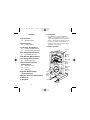
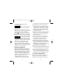
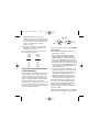
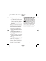
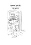
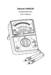
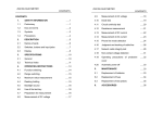
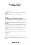
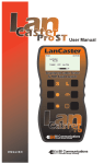
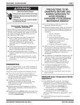
HSP5 3-09 manual.qxp
5/8/09
9:57 AM
Page 1
Analog Multimeter
Owners Manual
• Read this owners manual
thoroughly before use and save
HSP5
99 Washington Street
Melrose, MA 02176
Phone 781-665-1400
Toll Free 1-800-517-8431
Visit us at www.TestEquipmentDepot.com
HSP5 3-09 manual.qxp
5/8/09
9:57 AM
Contents
1. Introduction
1.1
Meter Functions
2. Specifications
2.1
For Your Safety
3. Operating Suggestions
3.1
3.2
Page 2
1. Introduction
The GMT-312 is an Analog Multimeter
capable of measuring 5 functions on 12
ranges. Small lightweight and rugged construction. This meter was designed for the
homeowner, hobbyist and professional
needing to make electrical and electronic
equipment measurements.
1.1 Meter Functions
Preliminary Adjustments
Internal Battery Condition
4. DC Voltage Measurement
4.1
200
Household Batteries
1K
30
40
100
20
60
10 8
5. DC Milliamp Measurement
6. AC Voltage Measurement
0
0
AC
dB
2K /V DC AC
FUSE & DIODE
PROTECTION
T
BA
+8 +12 +16
REP
LACE
150
30
6
+18
?
+20
GO
OD
0
200
30
0
40
8
250
50 DC
10
AC AC V ADD
+22 dB RANGE dB
10
0
50
14
250
28
500
34
0dB:1mW600
SP-5A
O HM
Multime te r
X1K OFF
0.5
–
50
Zero
Ohms
Adjust
ment
DC V
150
150
300
!
COM
10
300V
MAX
Battery/
Fuse
Cover
Mechanical
Zero
Adjust
Screw
10
DC
mA 50
300
50
150
AC V
V
MAX
300V
AC/DC
Input Jacks
Figure 1
1
1
24
0
A na lo g
Extension Cords
Fuses
Switches
8. Decibel Measurement
(Transistor Gain)
9. Battery and Fuse Replacement
10. Warranty
11. Disposal
2
BA
T
Wall Receptacles
7. Resistance/Continuity
Measurement
7.1
7.2
7.3
-20 0
3
180
100
20
4
50
10
2
DC 0
6 5
4
120
60
0
6.1
Analog
Scale
Needle
2
+
A
Function/
Range
Selector
Switch
HSP5 3-09 manual.qxp
5/8/09
9:57 AM
2. Specifications
Ranges:
DC Voltage:
AC Voltage:
DC Current (Milliamperes):
Resistance (Ohms):
Decibels:
Accuracy:
Sensitivity:
Function/Range Switch:
Zero Ohms Adjustment Dial:
12 measuring ranges
10-50-150-300 Volts
10-50-150-300 Volts
0.5-50-150mA
Rx1K (resistance indicated multiplied by
1000)
1 Megohm max
-20dB to +56dB on AC voltage ranges
DC voltage, mA = ±4% full scale of range
AC voltage = ±5% full scale of range
Resistance = ±4° arc of scale length
2000 ohms per volt DC and AC
5 functions
13 positions
12 measuring ranges
Located on the left side of the housing;
adjustment dial is used to zero the needle
indicator on the ohms scale while
shorting the test leads together.
Mechanical Zero
Adjustment Screw:
Located directly below the center of the
meter scale; adjust needle indicator to
read zero at the left side of the scale
before taking any measurement.
Recessed Input Jacks:
Negative (-) input jack for black test lead,
positive (+) input jack for red test lead.
Fuse Type:
F200mA H, 250V, GB GF-0306
Power Source:
One 1.5V AA size (non-rechargeable) battery
Test Lead Type:
ETL, cETL, CATII 300V 1A
Size (L X W X H):
approx 93mm X 62mm X 32mm
Weight:
approx 117g (including battery)
Agency Approvals:
ETL cETL, CATII 300V
Operating Temperature:
64F-77F (18°C-25°C)
Note:
Accuracy is given for one year, at 23°C ±
2° RH<60%
This multimeter was designed to be safe at least under the following conditions
Indoor Use
Altitude:
up to 2000m
Pollution degree:
2
Ingress Protection Degree:
IP20
Important:
Read this operators manual thoroughly before
using this multimeter. This manual is intended
to provide basic information regarding this
multimeter and to describe common test
procedures which can be made with this unit.
Many types of appliance, machinery and
other electrical circuit measurements are
not addressed in this manual and should
be handled by experienced service
technicians.
3
Page 4
! WARNING Use extreme caution when
using this multimeter. Improper use of
this meter can result in severe damage to
property, severe personal injury or death.
Follow all instructions and suggestions in
this operators manual as well as normal
electrical safety precautions. Do not use
this multimeter if you are unfamiliar with
electrical circuits and proper test procedures.
2.1 For Your Safety
The marking “ ” on the multimeter represents
Caution, risk of electric shock.
The marking “ ” on the multimeter represents Caution,
risk of danger, important information, refer to the manual.
In order to find out the nature of the potential HAZARD
and any actions which have to be taken consult the
manual in all cases where “ ” is marked.
The marking “ ” on the multimeter represents
Functional earth terminal.
The marking “ ” on the multimeter represents
Equipment protected throughout by DOUBLE
INSULATION or REINFORCED INSULATION.
Measurement category II is for measurements
performed on circuits directly connected to the low
voltage installation. Examples are measurements
on household appliances, portable tools and
similar equipment.
1)Use extreme caution when checking
electrical circuits.
2) ! WARNING Do not stand in wet or damp
work areas when working with electricity.
Wear rubber-soled boots or shoes.
3) ! WARNING Do not apply more voltage
!
!
4
HSP5 3-09 manual.qxp
5/8/09
9:57 AM
or current than the set range of the
multimeter will allow.
4) ! WARNING Do not touch the metal
probes of the test leads when making a
measurement.
5) Replace worn test leads. Do not use test
leads with broken or tattered insulation. Only
test leads meeting ETL, cETL, CAT II
300V IA can be used in this multimeter.
6) Discharge a capacitor before measuring it.
7) Remove the test leads from the circuit being
measured as soon as the test is completed.
8) ! WARNING Do not measure voltage
when the function/range switch is set on
the resistance (ohms) or the current (mA)
settings. Never measure current when the
meter is set on the resistance range.
Never measure AC voltage when the
meter is set on DC voltage or DCmA.
Setting the meter on the incorrect function
may burn out some of the internal circuitry
and may pose a safety hazard.
3. Operating Suggestions
1) Set the function/range switch to the proper
position before making a measurement.
When the voltage or current is not known, it
MUST be determined that the capacity of
the selected range will handle the amount of
voltage or current in the circuit (see #3
under For Your Safety). Always start with the
highest range in the function. If the
reading falls within the range of a lower
setting, reset the function/range switch to
5
Page 6
the appropriate setting for greater accuracy.
2) Avoid placing the meter in areas where
vibration, dust or dirt are present. Do not
store the meter in excessively hot, humid
or damp places. This meter is a sensitive
measuring device and should be treated
with the same regard as other electrical
and electronic devices.
3) Using the meter in areas with high magnetic
fields can result in inaccurate readings. For
greatest accuracy, lay the meter flat on a
non-metallic surface.
4) When the meter is not in use, keep the
function/range switch in the OFF position.
This keeps the needle indicator from
deflecting or ”bouncing” excessively.
5) When disconnecting the test leads from
the unit, always grasp the leads where the
input jacks meet the meter housing. Never
pull the leads out of the jacks by the
insulated wire or transport the meter using
the test leads as a carrying strap.
6) Never immerse the meter in water or
solvents. To clean the housing use a damp
cloth with a minimal amount of mild soap.
7) If the resistance (ohms) function of the
meter is not going to be used for a week or
more, remove the internal battery to avoid
potential leaks that may damage the unit.
3.1 Preliminary Adjustments
Fully seat the test leads in the correct input
jacks. If necessary, using a small flat tip
screwdriver, slowly turn the mechanical zero
6
HSP5 3-09 manual.qxp
5/8/09
9:57 AM
adjustment screw clockwise or counterclockwise until the needle indicator is directly over
the three black zeros at the left end of the scale.
Analog Meter: Reading the Scale
200
100
40
1K
5
10
20
120
4
5
2
1
180
Resistance
(Ohms)
Scale
Page 8
Decibel Gain (dB) - see pg. 15
Use the scale marked dB to read decibels for
transistor gain. Use the chart at the right of
the scale for proper conversion.
3.2 Internal Battery Condition
The first step in reading the analog scale is to
align the needle with the scale.
Before making resistance or continuity tests,
check the condition of the internal battery. First
turn the function/range switch to the ohms
Rx1K position. Short the test leads together
and the needle indicator should deflect to the
right side of the scale. Keep the test leads
shorted together while simultaneously turning
the zero ohms adjustment dial until the needle
indicator reads zero at the right side of the
ohms (green) scale. If the needle will not zero,
replace the battery with a new 1.5 volt AA size
non-rechargeable battery (see Battery
Replacement).
Resistance (Ohms - Ω)
4. DC Voltage Measurement
0
60
60
30
90
DC
240
}
120
300
150 DC Voltage
& Milliamps
Scale
6
8
AC Voltage Scale
General
dB Scale for Transistor
Gain Measurement
Common Markings
for both the AC & DC
Voltage Scales
Use the top scale for reading the resistance.
If the meter is set to X1k, multiply the
resistance value by 1000Ω.
DC Voltage (V DC)
Use the middle scale. Match the dial setting to
the highest number on the scale.
AC Voltage (V AC)
Use the same numbers and procedures as
used for the DC voltage setting, but use the
scale directly below the numbers.
DC Milliamps
Use the same scale and procedure as used
for the DC voltage setting.
7
1) Fully seat the test leads in the correct input
jacks, (-) black lead, (+) red lead.
2) Set the function/range switch to the
appropriate DC voltage range. If the voltage
is unknown, use the highest range. If the
voltage applied falls within the range of a
lower setting, reset the function/range switch
to the appropriate setting for greater accuracy.
3) If the polarity of the circuit to be tested is
known, touch the black test lead to the
neutral side. If the polarity is unknown, touch
the test leads to opposite sides of the circuit.
If the needle indicator deflects to the left of
the scale, reverse the test leads.
8
HSP5 3-09 manual.qxp
5/8/09
9:57 AM
Use the chart below as a guide to reading DC
voltage measurements:
DC V
Read
range
following
setting
scale
10
50
150
300
0-10
0-50
0-150
0-300
4.1 Household Batteries
Set the function/range switch to 10V DC to
test household 1.5 volt through 9 volt batteries.
Touch the red (+) test lead to the (+) terminal
and the black (-) test lead to the (-) terminal
of the battery. Read the 0-10 scale to
determine the condition of the battery.
5. DC Milliamp Measurement
1) Fully seat the test leads in the correct input
jacks, (-) black lead, (+) red lead.
2) Set the function/range switch to the
appropriate DCmA setting.
3) Touch the test leads to the circuit in series (in
line with the circuit) so that the circuit current
passes through the multimeter in order to
make the measurement. If the needle indicator
deflects to the left, reverse the test leads.
DC mA
Read
and
range
following multiply
setting
scale reading by:
0.5
50
150
0-50
0-50
0-150
9
0.01
1
1
Page 10
Common DC Milliamperage
Measurements
It is important to point out that milliamps can
also be expressed as thousandths of an
Ampere; therefore 150 milliamps is 150
thousandths of one Amp. The 150mA function
of your multimeter is commonly used by
electronics repair technicians and hobbyists to
troubleshoot various low voltage circuits.
Although not normally used for electrical
troubleshooting around the home, this function
can be used to measure the milliamperage
draw of household items such as flashlights,
and other battery operated devices that do not
draw more than 150 mA. In fig. 2 the red (+)
test lead is hooked up to the (+) terminal of the
lantern battery while the black (-) test lead is
hooked up to the bulb. The meter will indicate
the milliamperage draw when the flashlight
switch is thrown in the ON position.
Figure 2
! WARNING Do not apply voltage to the
test leads while the meter is set in the
milliamp range. See #8 For Your Safety.
6. AC Voltage Measurement
1) Fully seat the test leads in the correct input
jacks (-) black lead, (+) red lead.
2) Set the function/range switch to the
10
HSP5 3-09 manual.qxp
5/8/09
9:57 AM
appropriate AC voltage range. If the
voltage is unknown, use the highest range.
If the voltage applied falls within the range
of a lower setting, reset the function/range
switch to the appropriate setting for
greater accuracy.
3) Touch the test leads to the circuit under
test. With AC voltage, the polarity of the
test leads is not a factor.
Use the chart below as a guide to reading
AC voltage measurements:
AC V
Read
range
following
setting
scale
10
0-10
50
0-50
150
0-150
300
0-300
Common AC Voltage Measurements
6.1 Wall Receptacles
If the receptacle is controlled by a switch, make
sure the switch is ON. Set the function/range
switch to 150V AC. Touch the test leads to the
“hot” and “neutral” slots of the receptacle (see
fig. 3A). The needle indicator should read 120V
AC on the 0-150 scale. To test for proper
grounding of the receptacle, touch one test lead
to the “hot” (narrow) side of the receptacle, and
the other test lead to the ground slot. The meter
should read 120V AC as before.
11
Page 12
Figure 3
3B
3A
7. Resistance/Continuity Measurement
For resistance and continuity testing POWER
MUST BE OFF:
1) Fully seat the test leads in the input jacks (-)
black lead, (+) red lead.
2) Set the function/range switch to the Rx1K
position (resistance indicated multiplied by
1000) and short the test leads together. Using
the zero ohms adjustment dial, slowly turn the
dial until the needle indicator reads -0- ohms at
the right end of the ohms scale. If the needle will
not zero, replace the internal battery with a new
1.5 volt AA size non-rechargeable battery (see
Battery Replacement).
3) Touch the test leads to the resistance or nonenergized circuit to be measured. Measure the
value of the reading on the green ohms scale
and multiply the reading by 1000. If you’re
making basic continuity tests, the needle
indicator should move all the way to the right
side of the ohms scale if continuity exists.
Note: When switching the unit back and forth
from ohms to other functions, always zero the
needle indicator before taking another reading.
Failure to zero the needle before taking
resistance/continuity measurements will result in
inaccurate readings.
Continuity tests are probably the most frequently
performed electrical troubleshooting procedures
12
HSP5 3-09 manual.qxp
5/8/09
9:57 AM
around the home. ALWAYS REMEMBER THAT
CONTINUITY CHECKS ARE TO BE MADE
WITH THE POWER TO THE CIRCUIT
TURNED OFF. Polarity of the test leads is not a
factor in making continuity checks.
Page 14
Figure 5
Figure 6
7.1 Extension Cords
Unplug the cord. Set the function/range switch to
the Rx1K position. Touch one of the test leads to
one of the metal prong ends of the cord, and
insert the other test lead in either one of the
receptacle slots on the other end of the cord,
making sure the test lead is making good contact
with the receptacle (see fig. 4). If the needle
indicator does not move to -0- ohms, insert the
test lead into the other receptacle slot, again
making sure of good contact. If the needle
indicator still does not move the cord has a break
and should be replaced.
7.3 Switches
Cut off the power source to the switch. If
necessary, remove the switch. Turn the switch to
the ON position and touch the test leads to the
switch terminals (see fig. 7). If the switch is
good, the needle indicator will move to -0ohms. If not, replace the switch. On other
switches such as three-way light switches or
double pole double throw (ON-OFF-ON)
switches, each ON position will need to be
tested. Alternate the test leads between the
switch terminals to determine which two
terminals control that ON position.
Figure 4
Figure 7
8. Decibel Measurement
7.2 Fuses
Note: With the power OFF, always remove a
fuse from its socket before testing it. With
cartridge fuses, touch the test leads to each
end of the fuse (see fig. 5). If the fuse is good,
the needle indicator will move to -0- ohms. If not,
replace the fuse. On plug-type fuses, touch the
the test leads on the bottom contact and the
other on the threaded metal contact (see fig. 6).
13
The decibel feature of this multimeter is for
transistor gain measurement in electronic circuits and should not be confused with audio
decibels. This function is used primarily by electronics technicians to measure the power gain
in transistors, and is rarely encountered in home
project applications.
14
HSP5 3-09 manual.qxp
5/8/09
9:57 AM
1) Fully seat the test leads in the correct input
jacks, (-) black lead, (+) red lead.
2) Set the function/range switch to any one of
the AC voltage ranges and read the decibel
measurement on the bottom (red) scale of
the faceplate. Based on the AC voltage range
you selected, you will need to compute the
actual measurement by using the decibel
conversion chart located at the bottom right
of the faceplate.
Important: For absolute decibel measurements,
circuit impedance must be at least 600 ohms. -0decibels = 1 milliwatt in a 600 ohm impedance
(equivalent to 0.775 volts across 600 ohms).
Page 16
11. Correct Disposal of this product
This marking indicates that this
product should not be disposed with
other household wastes throughout
the EU. To prevent possible harm to
the environment or human health
from uncontrolled waste disposal, recycle it
responsibly to promote the sustainable reuse
of material resources. To return your used
device, please use the return and collection
systems or contact the retailer where the
product was purchased. They can take this
product for environmental safe recycling.
9. Battery and Fuse Replacement
1) Remove the screw in the back cover of the
meter and carefully separate the back cover
from the front.
2) Note the polarity of the battery when
removing it from its compartment and replace.
3) Use F200mA 250V replacement fuses, GB
model GF-0306
4) Carefully replace the back cover and tighten
the screw. Do not overtighten, as this may
strip the threads in the meter housing.
10. Warranty
1 YEAR WARRANTY limited solely to repair
or replacement; no warranty of
merchantability or fitness for a particular
purpose. Product is warrantied to be free
of defects in materials and workmanship
for the normal life of the product. In no
event shall Gardner Bender be liable for
incidental or consequential damage.
15
16