1
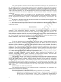
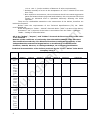
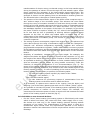
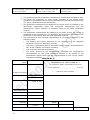
“OCHAG”, “GEYSER”, “VULKAN”
ELECTRODE BOILERS
OPERATION MANUAL
Contents
2
The given Operation manual contains basic information relating to the practical use of
the electrode boilers for the heating systems. By the aggregative technical and economic
indices of effectiveness, including the boiler efficiency, simplicity of installation and repairing,
cost of heating of one square meter of the apartment, specific consumption of materials per
1 kW of the boiler capacity, etc. the electrode boilers cannot be compared with any other type
of the electric boilers. The areas of application of the electrode boilers continue to extend
confidently.
This Operation manual is intended for the electrode boiler installation specialists,
experts in the installation of the automatic control systems for the electrode boilers, startingup and adjustment specialists, experts in maintenance and repairing, and owners of the
boilers.
We thank in advance those who will send remarks and proposals to the address of the
“Firma “GALAN” Joint-Stock Company.
All rights reserved. None of the parts of the given Operation manual can be reproduced
in any form without written permission of the “Firma “GALAN” Joint-Stock Company which is
a copyright owner.
Introduction
Invention of the electrode boiler is a one of the highest achievements in the area of
creation of the multipurpose heating equipment. A long-term experience of successful
operation shows that electrode boilers are easy operating, reliable, and safety devices. The
boiler efficiency reaches 98%. This is a result of application of one of the best achievements
of the domestic defensive industry in peace purposes. Throughout many years the boilers of
the “Firma “GALAN” Joint-Stock Company are successfully applied in almost all regions of the
Russian Federation, Post-Soviet republics and other foreign countries.
Dear customer!
To use a complete set of advantages of our boilers and to avoid possible annoying
errors in the process of installation of the heating system and boilers and in the course of
starting, further operation, and usage of the electric boilers, we convincingly ask you to
familiarize yourself attentively with the given Operation manual which contains information
relating to the characteristics, construction, operating principle, application, and rules of
installation of the electrode boilers. Also this Operation manual contains basic requirements
imposed on the safety measures, installation, operation, and repairing of the heating system,
registration and maintaining of the working documentation, etc.
The boilers are intended for heating of apartment houses, including country houses,
cottages, multistory apartment houses, garages, baths, premises and buildings of the
domestic, household, trading, public, industrial, and agricultural purpose, and also other
constructions in absence or inefficiency of the centralized heating.
The “Ochag”, “Geyser”, and “Vulkan” instantaneous electrode heating boilers produced
by the “Firma “Galan” Joint-Stock Company (hereinafter referred to as “boilers”) are used
only in the looped heating systems working without extraction of hot water for household,
industrial or any other purposes. These heating systems work on the basis of the compulsory
circulation of the heat-transfer agent (by means of the circulation pump). According to the
recommended most economic mode the temperature on an inlet of the boiler should lie in the
range +35 ÷ +45° С, and the temperature on an outlet of the boiler should fall in the range
+65 ÷ +75° C.
These boilers are made only in Russia.
The specified temperature in the heated premises is supported by the automatics (by
means of the temperature regulator).
The boilers have a long operating mode.
For normal operation of the boiler the following conditions are necessary:
* Operation air temperature of the premises in which the boiler is installed
should lie in the range between +10 to +35° С; ultimate air temperature of
the premises in which the boiler is installed should fall in the range between
3
+10 to +40º C (under condition of absence of other requirements);
* Relative humidity of an air at the temperature of +20° С should be no more
than 75%;
* Non-explosive environment; the environment should not contain aggressive
gases and steams destroying metal and isolation; the environment should not
contain an industrial dust in quantities adversely affecting the boiler
operation.
There are no combustible materials in the construction of the boilers, therefore our
boilers are fireproof.
Boilers meet the requirements of the Technical Specifications (TS) No. 346800117289826-02.
Order designations: “Galan – XXX-№” electrode boiler (“XXX” is a name of the boiler).
Annotation: “№” is a power of the boiler in accordance with the Table 1. Example:
“Galan – Ochag-6” electrode boiler.
All of the “Ochag”, “Geyser”, and “Vulkan” electrode boilers described in the Table
1 are certified.
Number of the certificate of conformity: РОСС RU.ME71.H00072 dated 29.03.05.
The Certification authority: The Electrical Products Certification Authority of the
Independent Noncommercial Organization on Certification of the Electrical
Products, 109052, Moscow, ul. Nizhegorodskaya, 29. Voluntary certification.
Technical characteristics of the boilers produced by the “Firma “Galan” Joint-Stock
Company Table 1
Name of the boiler
Boiler
characteris
tics
1.
S
Ochag-2
Ochag-3
Ochag-5
Ochag-6
Geyser-9
Geyser15
Vulkan-25
80
120
175
200
340
550
850
2
3
5
6
9
15
25
220
220
220
220
380
380
380
0,5
0,75
1,25
1,5
2,5
4
6,6
ize of
the
heated
space
(cubic
meter
s)
2.
N
ominal
power
consu
mptio
n
(kW)
3.
N
ominal
voltag
e (V)
4.
pproxi
mate
energ
y
consu
mptio
n
(kW/h
) (with
4
A
Name of the boiler
Boiler
characteris tics
Ochag-2
Ochag-3
Ochag-5
Ochag-6
Geyser-9
Geyser15
Vulkan-25
9,1
13,7
22,7
27,3
13,7
22,7
37,5
10
16
25
32
3x16
3x25
3x40
4
4
4
6
norma
l
therm
al
protec tion
of premis
es)
5.
M ax.
curren
t
streng th
of the
boiler on
each phase
(A) (curre
nt freque
ncy – 50
Hz)
6.
N
ominal
curren
t
streng th of
the
autom
atics (A),
electro
mecha
nical
model
7.
C
ross sectio
n of
curren
tcarryi ng
copper
conne
ction cable
core (sq.
mm)
9. Max.
(operat ing)
temper
ature of
the
heattransfe
r agent on
the
5
220 V
4
380 V
90
4
6
Name of the boiler
Boiler
characteris tics
Ochag-2
Ochag-3
Ochag-5
Ochag-6
Geyser-9
Geyser15
Vulkan-25
20-40
25-50
30-60
35-70
50-100
100-200
150-300
25
25
25
25
32
32
32
outlet of
the
boiler
(ºC)
10.Recom
mende
d volume
of the
heattransfe
r agent in
the heating
system
(liters)
11. Nomin
al
diamet
er of
couplin gs
for
connec ting
to the
heating
system
(mm)
1
12. Class of
protect ion
against
electric
shock
hazard
IP X3 splash-proof
13. Constr
uction by
moistu re
proofin g
degree
14. Length
250
275
320
335
360
410
460
0,85
0,9
1,05
1,1
5,0
5,3
5,7
(mm)
15. Weight
(kg)
6
16. It is recommended to use the following types of liquids as heat-transfer agents for all of the “Ochag”, ”Geyser”,
“Vulkan” electrode boilers of the “Firma “Galan” Joint-Stock Company which are listed in this table:
•
“Galan-Potok” low-freezing liquid with special rust prevention components and additives against formation of
scale and scum (freezing temperature: -40º C, life expectancy: no less than 5 years, warranty period: 1 year)
(hereinafter referred to as “low-freezing liquid”);
•
Potable water (defined by the Sanitary Regulations and Rules No. 2.1.4.559-96), distilled water, snow melt water,
rain water (filtered water) the specific electric resistance (hereinafter referred to as “resistance”) of which is no
less than 1300 Ohm/cm at a temperature of +15º C.
ATTENTION!
It is strictly forbidden to use low-freezing liquids (antifreezes) such as “TOSOL”, “Arktika”, “Tvoy Dom”, etc. as heatName of the boiler
Boiler
characteris tics
Ochag-2
Ochag-3
Ochag-5
Ochag-6
Geyser-9
Geyser15
Vulkan-25
transfer agents since they are not intended for a use by the electrode boilers.
The “Firma “Galan” Joint-Stock Company regularly performs technological
improvements of electric boilers, therefore their technical characteristics can slightly differ
from characteristics resulted in the table above.
Boilers construction
Depending on the boiler power the electrode boilers produced by the “Firma “Galan”
Joint-Stock Company fall into the following categories:
•
Single-phase electrode boilers (“Ochag-2”, “Ochag-3”, “Ochag-5”, and “Ochag6” electrode boilers);
•
Three-phase electrode boilers (“Geyser-9”, “Geyser-15”, and “Vulkan-25”
electrode boilers).
Single-phase electrode boilers consist of the following components:
•
Metal case with inlet and outlet connections (a case functions as the second
electrode and ionization chamber);
•
•
Rod electrode with current lead and hermetic electric bushing insulator;
Two terminal groups with protective housings (phase terminal is located at the
bottom of the single-phase electrode boiler; neutral wire terminal and ground
wire terminal are on the side of the single-phase electrode boiler).
Three-phase electrode boilers consist of the following components:
•
Metal case with inlet and outlet connections (a case functions as ionization
chamber);
•
Base on which three electrodes with current leads and hermetic electric bushing
insulators are installed;
•
Terminal group with protective housing.
The operating principle is the same for all electrode boilers. It is discussed below.
Advantages of the electrode boilers
The electrode boilers of the “Firma “Galan” Joint-Stock Company are 2-3 times cheaper
than the boilers of the same power produced by other manufacturers and have the following
significant advantages:
•
7
Significant energy conservation is achieved by high electrode boilers efficiency
which reaches 98%. By this indicator electrode boilers surpass the existing
heating boilers of other types. This advance has come about through the direct
transformation of electric energy to thermal energy in the heat-transfer agent
during the passage of electric current through the heat-transfer agent. Under
these conditions the ionization of the heat-transfer agent takes place. The
temperature and electrical conductance of the heat-transfer agent grow. The
strength of electric current passing from one electrode to another grows too.
The electrode boiler is brought to nominal power quickly.
•
The pressure of the heat-transfer agent on the boiler outlet comprises up to 1
atm. without usage of the circulation pump. This advance has come about
through the using of ionization chamber of small size which provides a sharp
heating of the heat-transfer agent and through the using of a standpipe which
is installed at a height of no less than 2 m. above the boiler. The “dy” value of
the standpipe depends on the power of the boiler. For example, for the boiler
the power of which is equal to 25 kW, the “dy” value of the standpipe should
be no less than 40 mm. A possibility of working without circulation pump
depends on the floor on which the heated space is located and on the
configuration of the heating system. Therefore our electrode boiler is at once a
heating device and a circulation pump. This results in considerable savings of
customer expenses.
•
The saving of power consumption ranges from 40% to 60%. This advance has
come about through the using of automatics which includes the “Navigator”,
“Istopnik 103” electronic temperature regulators, “Istopnik 203” electronic
programmable temperature regulator, “Galan GSM” cellular monitoring system
of the heating equipment, and electromechanical model of the automatics. Also
this advance has come about through the high performance of the electrode
boilers.
•
Simplicity of installation, compact size, and light weight. For example, the
weight of the boiler the power of which is equal to 6 kW comprises 1,1 kg, and
the weight of the boiler the power of which is equal to 25 kW comprises 5,7 kg.
•
It is possible to build our electrode boilers in earlier installed heating systems
(also as secondary reserve boilers by using parallel connection) under the
condition of obligatory performance of our recommendations (Fig. 3). The
power of the reserve boiler should correspond to the size of the heated space,
quality of the thermal protection, and volume of the heat-transfer agent in the
heating system (Table 1). In case of installing of the reserve boiler in running
heating system it is necessary to perform the following tasks:
o To wash the heating system carefully by means of the “GalanProtektor” rust inhibitor; o To
filter the heat-transfer agent;
o To take measures for preventing ingress of contamination from the
heating system to the boiler and to install the filters.
It is necessary to replace some meters of the ingoing (into the boiler) and
outgoing (out of the boiler) plastic pipes with not zinc-coated (“black”) pipes.
•
It is possible to increase the power of the heating system repeatedly by using
parallel connection of number of the electric boilers. For example, the
connection of 8 boilers the power of which is equal to 25 kW increases the total
power of the heating system to 200 kW (Fig. 2).
It is forbidden to use electrode boilers:
•
8
For the “direct” water heating (the heating system is filled directly with water
which is taken from basin, well, water-well hole, water-supply line or river).
Our boilers are used only in the looped heating systems working without
extraction of hot water. The characteristics of water which is used as a
heattransfer agent should meet the requirements specified in the boiler’s
Operation manual. Non-observance of these requirements results in the boiler
breakage.
•
For “warm floors” construction. The temperatures required for the “warm
floors” construction are considerably lower than the optimal operating
temperatures of the electrode boilers. For this reason a boiler is not brought to
nominal power. We recommend you to use highly reliable modern tubular
electric heating boilers produced by the “Firma “Galan” Joint-Stock Company
for “warm floors” construction.
It is not recommended to use electrode boilers in the heating systems in which large
heating radiators (radiators which use pipes of big diameter, cast-iron radiators, etc.) are
installed. In this case we also recommend you to use tubular electric heating boilers produced
by the “Firma “Galan” Joint-Stock Company.
If you need to use electrode boiler by force of circumstances, it is necessary to provide
the conformity of volume of the heat-transfer agent filled in the heating system to the boiler
power (Table 1). Besides, in case of using cast-iron radiators it is necessary to install a strainer
or mud settler in the return pipe to prevent the situation in which the remaining volume of
the core sand with the heat-transfer agent is brought into the boiler from the cast-iron
radiators resulting in the boiler breakage. With that end in view it is necessary to wash castiron radiators carefully before installing them into the heating system.
Recommended complete set of delivery
•
•
•
•
•
Boiler as an assembly – 1 item.
The electrode boiler operation manual and reference guide – 1 item.
Automatics* – 1 complement.
Automatics operation manual** – 1 item.
Package – 1 item.
Note:
* - One of the models of the automatic control units produced by the “Firma “Galan”
Joint-Stock Company is chosen.
The warranty is not applied to the boiler which is purchased without this automatic
control system.
The electrode boiler cost does not include a cost of the automatic control unit.
** - With the exception of the operation manual for electromechanical model of the
automatics which is a part of this Operation manual.
The contents of this offered model of the automatics can be altered.
Installation of the electrode boiler into the heating system
The heating systems designing, boilers and automatics installation tasks, power
network and grounding connection tasks, putting into operation and repairing tasks,
equipment examination and testing tasks should be performed by the organization (firm)
having the corresponding license for performing these tasks.
On performing the tasks listed above the provisions of the following documents should
be observed:
•
•
•
•
•
“Inter-branch rules for electric installations”.
“User rules for operating electrical equipment”.
“Safety rules for operating electrical equipment”.
“User and safety rules for operating electric boilers and boiler-houses”.
The given Operation manual.
Also it is necessary to observe the provisions of the corresponding Construction
Regulations and Rules and the Fire prevention rules of the Russian Federation.
It is necessary to employ the electricians or control equipment and automatics
specialists of the corresponding qualification for connecting the boiler, installing the automatic
control systems for the heating equipment, and performing the servicing and repairing tasks.
9
These specialists should be certified by the electrical safety rank which is no less than a rank
of 3 and should be allowed to work with electrical installations operating at the voltage up to
1000 V. To perform the installation, operation, and repairing of the heating systems it is
necessary to employ the heating engineers. The specialists listed above should be acquainted
with the “User and safety rules for operating electric boilers and boilerhouses” and the given
Operation manual. In the process of working with rust inhibitor, lowfreezing liquid, washing
and clearing agents it is necessary to follow the safety rules for using these substances. On
completion of the tasks listed above the organization (firm) which has performed these tasks
should make an entry in the List (Appendix No. 2) which is assured by the person responsible
for performing these tasks and by the seal of this organization.
Visual examination of the boiler operation can be made by the instructed persons no
younger than 18 years old. These specialists should be acquainted with the given Operation
manual, the boiler construction, and safety rules for visual examination of the boiler
operation.
Connecting the boilers to the power networks of the supply authority
In case of the lack of the allocated power the boiler connecting is performed in
accordance with the established procedure.
It is necessary to note that this procedure of connecting the electric boilers to power
networks is applied to the electric boilers of other types and is not the distinctive feature of
the electrode boilers.
Grounding
By the time of boiler installation the heating system should have the completely
accomplished and tested grounding. The value of resistance of the boiler grounding and the
value of resistance of the heating system grounding should be no more than 4 Ohm. The
copper wire with the cross section of 4-6 sq. mm is used as the conductor for the grounding
(Table 1).
The arrangement of the protective grounding should meet the requirements of the
“Inter-branch rules for electric installations” and the “User and safety rules for operating
electric boilers and boiler-houses”.
All of the open current-conducting parts of the boiler and heating system including
metal pipelines for the cold (return pipe) and hot heat-transfer agent should be grounded.
The place of entering of the conductors into the building or construction should be
marked by the identification sign.
Grounding electrodes
The construction of the grounding electrodes should meet the requirements of the
“Inter-branch rules for electric installations”.
The construction and arrangement of the grounding electrode should provide the
required value of resistance of the boiler grounding and the value of resistance of the heating
system grounding which is no more than 4 Ohm.
The periodical review period of grounding electrode state comprises 12 years.
The rusting wear should not exceed 50%.
It is forbidden to paint the grounding electrode and to safeguard the grounding
electrode against rust by means of the removable or permanent dielectric coating (for
example, rubber or plastic cover).
Before the installation procedure it is necessary to examine the boiler and to check the
completeness of the equipment.
The boiler is installed only vertically into the heating system.
A terminal group (current leads of the boiler) protected from the external influence or
casual touching by the protective housing should be located at the bottom of the boiler. A
phase terminal of the “Ochag” (220 V) electrode boilers should be located at the bottom of
the boiler. It is necessary to use couplings for connecting the boiler connections to the
pipelines of the heating system. A nominal diameter of these couplings should meet the
10
project documentation requirements of your heating system and should be no less than the
nominal diameter of the boiler connections.
In the course of the heating system designing it is necessary to install the boiler as
low as possible in relation to the radiators. This increases a pressure on the boiler outlet. It
is desirable to allow vertical clearance for easy removing the electrode group from the boiler
and for visual examination and cleaning of the internal surfaces of the boiler.
The diameter of vertical standpipe above the boiler and the diameters of all of the
pipelines of the heating system should meet the project documentation requirements of your
heating system. The height of vertical standpipe above the boiler should be no less than 2 m.
It is a reason for abandoning a use of the circulation pump.
Irrespective of the way of connecting the boiler to the heating system, the boiler should
be fastened to a wall in the process of the assembly.
Some of the key diagrams of the heating systems arrangement are depicted in
Figures 1, 2, 3. For the easy maintenance of the heating system it is necessary to locate the
shutoff valves on the pipeline right after the surge tank and before the inlet connection of the
boiler (see Figures 1, 2, 3).
It is strictly forbidden to install valves and other regulating or locking
mechanisms on the pipeline between the boiler outlet connection and the surge
tank.
Electrical installation of the boilers and automatics
Three-phase electrode boilers are connected to the four-wire three-phase power
network the voltage of which is equal to 380 V. Industrial frequency of the current is equal to
50 Hz. N is a neutral conductor, and PE is a protective conductor of grounding. N and PE
conductors are decoupled.
Single-phase electrode boilers are connected to the single-phase power network the
voltage of which is equal to 220 V. N is a neutral conductor, and PE is a protective conductor
of grounding. N and PE conductors are decoupled.
Connect the electrode boiler to the power network in accordance with the project
documentation of your heating system and the chosen model of the automatics produced by
the “Firma “Galan” Joint-Stock Company.
The observing of the “Phase-Null-Ground” is obligatory!
Cross section of all wires should be similar and no less than a value specified in the
Table 1 (electromechanical model of the automatics) of the given Operation manual or no less
than a value specified in the operation manual of the chosen electronic model of the automatic
control unit of the heating system.
11
Fig. 1 Heating system with top pouring
Label number
1.
2.
3.
4.
5.
Fig. 2 Parallel connection.
Electromechanical model of the automatics
Name of the equipment
Electrode boiler
Radiator
Surge tank
Reserve electrode boiler
Main boiler running on
solid, liquid or gas fuel
Legend
- Laid-on thermostat
(sensor)
- Valve
- Filter (mechanical
mud settler)
- Heat-transfer agent
drain valve
- Air drain valve
- Circulation pump
(power – 70 or 100
W)
A – Vertical settler of height which is no less than
2 m. located above the boiler.
The diameter should meet the project
documentation requirements of the heating
system without circulation pump depending on
the floor and the size of the heated premises.
B – Difference in height (no less than 1,5 m.)
Fig. 3 Reserve electrode boiler connection diagram
12
It is necessary to use the connection diagrams specified in the Operation manual to
connect the “Galan-GSM” cellular monitoring system of the heating equipment, “Navigator”,
“Istopnik-103” and “Istopnik-203” electronic temperature regulators. Follow exactly the
instructions of operation, installation, and safety control.
The “Inlet” temperature sensor is installed on the pipeline (return pipe). The “Outlet”
temperature sensor is installed on the pipeline coming from the boiler (vertical standpipe) at
30 cm. from the boiler outlet (boiler connection).
The recommended optimal operating temperatures of the heat-transfer agent on the
inlet and outlet of the boiler are specified in the “Introduction” section of the given Operation
manual. The observation of these temperature modes assures the greatest effect of using the
electrode boiler.
The range of thermoregulation of the “Navigator” temperature regulator on an outlet
of the boiler stretches from +10 to +90° С (“Outlet” indicator). The range of thermoregulation
of the “Navigator” temperature regulator on an inlet of the boiler stretches from +10 to +60°
C (“Inlet” indicator).
When employing the “Istopnik-103”, “Istopnik-203”, and “Galan-GSM” temperature
regulators the temperature is measured directly in the heated premises. The usage of these
devices increases the effectiveness of the heating system and makes the heated premises
more comfortable.
Use a copper wire with a value of cross section lying in the range between 0,5 to 2,5
sq. mm for installation of the automatic control unit of the heating system. A wire make-up
should be specified in the project documentation of your heating system and in the automatic
control unit operation manual. In case of applying copper stranded wire use a thimble but do
not tin an end of the wire because it may bring into existence a bad contact.
Automatic control units of the heating systems produced by the “Firma “Galan”
Joint-Stock Company
In the course of starting-up and adjustment tasks and on the basis of the specific
situation the following temperatures are set on the “Navigator” temperature regulator:
•
•
Temperature on the outlet of the boiler (a value belonging to the recommended
optimal operating temperatures range which stretches from +65 to +75º C) at
which the boiler is switching off obligatory in any condition
(temperature which is set on the boiler outlet). As a rule, this temperature is
equal to +70º C.
Temperature on the inlet of the boiler (a value belonging to the recommended
optimal operating temperatures range which stretches from +35 to +45º C) at
which the boiler is switching off obligatory in any condition (temperature which
is set on the boiler inlet).
A hysteresis setting (specific number of Celsius degrees by which the temperatures on
the inlet and outlet of the boiler should be decreased in comparison with the specified
temperatures in order that the temperature sensors on the inlet and outlet of the boiler
(“Inlet” sensor and “Outlet” sensor) should send commands for switching off the boiler) is
also set on the “Navigator” temperature regulator.
A value of the hysteresis setting belongs to the temperature range of the adjustable
hysteresis of the “Navigator” temperature regulator. This temperature range stretches from
1 to 9º C.
A hysteresis setting for the “Outlet” sensor, as a rule, is equal to 9º C.
A hysteresis setting for the “Inlet” sensor is strictly individual for every heating system.
It is defined both by the objective factors (for example, match between the heat losses of the
heated premises and the power of the heating system) and by the subjective factors (for
example, requirements on the comfort of the heated premises, requirements on the operating
economy of the heating system).
With the exception of particular cases, in the course of the cold season the hysteresis
settings, as a rule, are not changed.
The boiler is switching off, as a rule, by the command of the “Inlet” sensor.
13
In case of emergency or malfunction of the heating system (in consequence of
deterioration of the heat-transfer agent circulation or increase of temperature on the outlet
of the boiler) the boiler is switched off by the command of the “Outlet” sensor.
The boiler is switching off by the command of the “Outlet” sensor in the following
cases:
•
Circulation pump stop by reason of power network connecting wire break or
rotor clogging.
•
•
Presence of the air locks in the heating system.
Leakage of portion of heat-transfer agent by reason of the heating system
depressurization.
•
Freezing of part of the heating system because of using water as a heattransfer
agent.
• Filter plugging.
The “Outlet” sensor comes into action only in case of emergency or malfunction of the
heating system.
The “Istopnik-103” electronic room temperature indicator and the “Istopnik-203”
electronic programmable room temperature indicator are used only in conjunction with the
“Navigator” control unit.
Relative to the “Inlet” and “Outlet” sensors of the “Navigator” control unit which are
installed on the pipeline, the “Istopnik-103” and “Istopnik-203” temperature regulators are
mounted directly in the heated premises. This increases the effectiveness of the heating
system and makes the heated premises more comfortable. Set up the required temperatures
in accordance with the operation manuals of these devices.
Contrary to the “Istopnik-103”, the “Istopnik-203” is a programmable device by means
of which it is possible to program or to specify the required room temperature changes by
hours of the day or by days of the week.
The “Galan-GSM” cellular monitoring system of the heating equipment makes it
possible to specify and maintain the necessary temperature indoors. This system makes it
possible to connect four additional sensors (security sensor, gas leak sensor, water flooding
sensor, etc.).
The “Galan-GSM” cellular monitoring system of the heating equipment is used in
conjunction with the “Navigator” control unit. Perform the installation in accordance with the
“Galan-GSM” and “Navigator” operation manuals.
Electromechanical model of the automatics. Preparation and putting into
operation.
Connect the boiler to a power network in accordance with the type and power of the
boiler (Diagram 1 or Diagram 2). The “Inlet” temperature sensor, as a rule, is installed on the
pipeline. The “Outlet” temperature sensor is installed on the pipeline coming from the boiler
at 30 cm. from the boiler outlet.
The sensors connecting is performed by means of the copper cable wire with cross
section of 0,5 – 2,5 sq. mm.
A circuit breaker is an automatic safety device which comes into action on current
overload. It is used for switching on and switching off the power supply of the boiler.
A button which is located on the automatic tripping contactor case is used for switching
on and switching off the thermal relay. Under normal operation of the power supply diagram
of the boiler, this button is always in the “on” (pressed) condition. The actuating of this button
signifies that consumption current exceeds the nominal current because of the malfunction of
the boiler (or the power supply diagram) or because of the water electrical resistance is equal
to 3100 Ohm/cm at temperature of +15º C. The thermal relay can be switched on by pressing
the button.
Set up a value of the required temperature on the outlet of the boiler (+ 65 ÷ +75º
C).
Set up a value of the required temperature on the inlet of the boiler. This value depends
on the size of the heated space, quality of the thermal protection of the apartment, etc. and
ranges, as a rule, from +35 to +45º C.
14
Diagram 1
No.
1.
Name of the
device.
Wire
“OCHAG” boilers (220 V)
2 kW
3 kW
5 kW
Circuit
10 A
16 A
25 A
breaker
2.
Automatic
tripping
size 2, up to 32 A
contactor
Automatic
2.1
220 V
tripping
contactor
coil
2.2
Thermal
normally closed
relay
contacts
3.
“Inlet”
temperature
sensor
laid-on bimetallic thermostat
4.
“Outlet”
temperature
sensor
5.
Boiler (2, 3,
5, 6 kW)
6.
Boiler
terminals
7.
Ammeter (or
power level
indicator)
Cross section of the copper connecting wire (sq. mm)
4
15
6 kW
32 A
17
Diagram 2
No.
1.
Name of the
device.
Wire
Circuit breaker
2.
2.1
2.2
Thermal relay
contacts
“Inlet”
temperature
sensor
“Outlet”
temperature
sensor
Boiler (bottom
view)
Boiler terminals
3.
4.
5.
6.
Boilers (380 V)
“Geyser”
9 kW
16 A
“Geyser”
15 kW
25 A
Automati
c
size 2,
tripping
up to 25
contacto
A
r
Automati
380 V
c
tripping
contacto
r coil
normally closed
“Vulkan”
25 kW
40 A
size 3,
up to 40 A
380 V
laid-on bimetallic thermostat
-
Cross section of the copper connecting wire (sq. mm)
4
4
Filling the heating system with heat-transfer agent
6
Your heating system is mounted. The boiler and automatic control equipment are
installed. The heating system is connected to the power network and to the grounding. There
is no mud and rust in the heating system.
In this case a process of filling a heating system with heat-transfer agent is performed
without preliminary washing. It is necessary to observe the following rules:
•
•
The heating system should be disconnected from the power network before the
filling a heating system with water or low-freezing liquid. It is necessary to
exclude unintentional connection to the power network.
It is necessary to check leak resistance of the heating system right after filling
a system with heat-transfer agent. Any leakages are inadmissible.
It is possible to fill a heating system with the “Galan-Potok” low-freezing liquid or with
water (Table 1).
Water as a heat-transfer agent has a number of indisputable advantages, such as
availability, cheapness, and ecological compatibility. Also water has good thermal properties.
Nevertheless, water has some disadvantages, such as heating system corrosion, possible
necessity for water specific electrical resistance correcting, annual boiler repair, etc. Therefore
we recommend you to use the “Galan-Potok” modern low-freezing liquid as a heat-transfer
agent for a heating system instead of water which also can be used for this purpose.
“Galan-Potok” low-freezing liquid
A universal “Galan-Potok” low-freezing liquid the freezing temperature of which is
equal to -40º C is designed with the aim of improving the reliability and economic efficiency
of a heating system operation. Low-freezing liquid has special additives against formation of
scum and scale on the walls of the heating system. Also the “Galan-Potok” low-freezing liquid
includes the additives used for inhibition of corrosion and for scale dissolving. The application
of low-freezing liquid saves from danger of “unfreezing” the heating system in the event of
sudden power supply disconnection. Also the usage of low-freezing liquid significantly
simplifies a heating system servicing because the parameters and properties of low-freezing
liquid completely meet the requirements of the heating system with electrode boiler. The
application of low-freezing liquid significantly improves the economic and performance
indicators of the heating system. In particular, the usage of low-freezing liquid simplifies the
execution of starting-up and adjustment, reduces the time intervals for performing these
tasks, provides the stable operation of the heating system, and reduces the expenses for the
heating system servicing.
Filling a heating system with low-freezing liquid
There is no mud and rust in the heating system. The heating system is filled with a
measured volume of low-freezing liquid through a drain valve by means of the pump (for
example, by means of the “Malysh” pump). After performing of exhaustion of an air from the
heating system, the filling of 1/3 of surge tank volume is accepted as normal.
Water as a heat-transfer agent
It is necessary to reduce or to increase the water specific electrical resistance
(hereinafter referred to as “correcting procedure”) for providing the electric boiler operation
with nameplate rating. Correcting (adjustment) of the water specific electrical resistance is
performed after filling a heating system with water by adding sodium salt solution or water
with high electrical resistance to water. In this way table values of the starting current
strength and maximum current strength (Table 2) at specified return pipe temperatures are
reached.
It is necessary to pay scrupulous attention to the instructions of the given Operation
manual:
•
The temperature on the inlet of the boiler (“Inlet” sensor) should lie in the range
+15 ÷ +20º C.
•
The boiler switching on durability should not exceed 30 seconds.
Correcting procedure
Switch on the boiler and measure starting current strength by ammeter or
splitelectromagnetic instrument after 30 seconds at the return pipe temperature of +15 ÷
+20º C. There are three possible situations: value of the starting current strength is lower
(higher) than the table value specified in the Table 2 or value of the starting current strength
is equal to the table value specified in the Table 2.
Table 2
No.
Boiler brand (name
of the boiler)
Power,
kW
Voltage,
V
Phases
Starting current strength of
the boiler at the return
pipe temperature of +15º
C, A
1
2
3
4
5
6
7
“Ochag-2”
“Ochag-3”
“Ochag-5”
“Ochag-6”
“Geyser-9”
“Geyser-15”
“Vulkan-25”
2
3
5
6
9
15
25
220
220
220
220
380
380
380
1
1
1
1
3
3
3
4
5
10-12
15-18
6-8 per phase
8-10 per phase
12-15 per phase
Max. current strength of
the boiler in the
specified mode at the
return pipe temperature
of +60º C, A
9,1
13,7
23
27
13,7 per phase
23 per phase
37 per phase
Value of the starting current strength is lower than the table value specified in the
Table 2.
17
The correcting procedure of the starting current is performed in the following way:
•
Clear sodium salt solution is prepared (1 teaspoon of sodium salt is dissolved
in 200 grams of hot water). This is an approximate volume of the solution per
100 liters of water filled in the heating system.
•
Single dose of the salt solution which is filled in 20 liters of water drawn off
from the heating system is defined depending on the difference between
measured value of the starting current strength and it’s table value (Table 2)
for your boiler (power of your boiler) and the volume of water filled in the
heating system.
•
Stir the dose of the salt solution and the water drawn off from the heating
system carefully.
•
This mixture is filled in the heating system through the drain valve by means
of the “Malysh” type pump.
•
Draw off 20 liters of water from the system once again and fill the heating
system with water without salt solution.
•
Switch on the circulation pump for 20-30 minutes. Running time of the
circulation pump depends on the size of the heating system and the volume of
water filled in the heating system. The switching on of the circulation pump is
required for equalization of the water parameters in the heating system.
•
Switch on the boiler and measure starting current strength after 30 seconds at
the return pipe temperature of +15 ÷ +20º C.
•
Switch off the boiler and compare the measured value of the starting current
strength with the table value for your boiler (Table 2). It is necessary to repeat
the correcting procedure in the event that the measured value of the starting
current strength is different from the table value. During the execution of the
correcting procedure the temperature on the inlet of the boiler should lie in the
range +15 ÷ +20º C.
•
It is necessary to switch on the heating system after equalization of the
measured value of the starting current strength and the table value. Once the
temperature on the “Inlet” sensor has reached the value of +60º C, measure
the maximum current strength and compare it with the value specified in the
Table 2. Perform the correcting procedure once again as the need arose. It is
necessary to note that the value of the starting current strength is a testing
value which simplifies the process of performing the correcting procedure. The
correcting procedure is finished when the value of maximum current strength
of the boiler at the temperature of +60º C on the inlet of the boiler (on the
“Inlet” sensor of the boiler) is equal to the value specified in the Table 2.
Value of the starting current strength is higher than the table value specified in the
Table 2.
In this case it is necessary to add water the specific electric resistance of which is
significantly higher than a value specified in the operation manual. This may be distilled water,
clear uncontaminated filtered rain water, snow melt water. Potable water with high specific
electric resistance (Table 1) can be also used. A volume of water which is added to the heating
system depends on the volume of water filled in the heating system. A procedure of adding
water with high specific electric resistance to the heating system is similar to a method of
adding salt solution in the event that the starting current strength and the maximum current
strength are lower than the value specified in the Table 2.
A volume of water with high specific electric resistance which is added to the heating
system should be equal to a volume of water drawn off from the system.
If the heating system works without circulation pump, a value of the specific electric
resistance can be changed by the following ways:
•
18
Increase the number of single additions of salt solution or water with high
specific electric resistance to the heating system.
•
Decrease the salt solution doses or volume of water with high specific electric
resistance added to the heating system.
•
Increase the volume of water pumped to the surge tank by means of the
“Malysh” type pump after each addition of salt solution or water with high
specific electric resistance to the heating system.
Switching on the boiler
Switch on the boiler and establish the most careful control over the boiler’s automatic
switching on and switching off.
It is inadmissible to switch on the boiler at presence of the frozen heat-transfer agent
in the system or in danger of freezing the heat-transfer agent.
The temperature of the premise in which the heating system is installed should lie in
the range + 15 ÷ +20º C.
In case of the heating system and the electrical connection diagram for the equipment
(including automatics) are mounted correctly, the system will start to get warm.
In case of gradual power decreasing of the boiler at the initial period of work (fresh
water as a heat-transfer agent) it is necessary to perform the following steps:
•
•
Remove the boiler from the heating system.
Disassemble the boiler and decontaminate the surfaces of electrodes and
internal surfaces of the boiler.
•
Assemble the boiler and install it into the heating system.
Preventive maintenance. Washing of the heating system
The purpose of this task consists in providing the reliable, effective, and long-term
work of the heating system. The task is performed by the qualified personnel. The heating
system should be disconnected from the power network.
The preventive maintenance is performed by the firm (organization) having the
corresponding license for performing these tasks. On completion of the preventive
maintenance the organization (firm) which has performed these tasks should make an entry
in the List (Appendix No. 2) which is assured by the person responsible for performing these
tasks and by the seal of this organization.
The preventive maintenance is performed after termination of the cold season. The
periodicity and composition of the preventive maintenance is defined both by the heattransfer
agent used in the system and by the defects detected during the operating and inspection of
the heating system and the boiler.
Water as a heat-transfer agent
Annually right after the ending of the cold season it is necessary:
•
•
To cool the heating system to the room temperature;
To draw off 20 liters of water from the system, to dissolve a dose of the
“Galan-Protektor” in this volume of water (1,5 liters of inhibitor per 100 liters of
water), to stir carefully, and to fill the heating system with this mixture through
the drain valve by means of the “Malysh” type pump. Draw off 20 liters of water
from the system once again and fill the hating system with water without inhibitor.
Perform these tasks up to the complete filling of the heating system with mixture
of water and inhibitor. For washing the system it is necessary to keep it working
through 6 days with the temperature of the return pipe of +35º C. During this
period the washing of the system and the corrosion protection (inhibition) of the
external surfaces of the system take place. At this time it is necessary to clear the
filter periodically. After six days of operating the heating system it is necessary:
•
•
•
To disconnect the heating system from the power network;
To cool the heating system to the room temperature;
To draw off water from the heating system completely.
This water cannot be reused. If required, the procedure can be repeated. It is
necessary to examine and check the tightening of the bolted and electrical connections, and
the reliability of grounding connection.
19
Boiler repair
Remove the boiler from the heating system. Remove the electrode group (electrode)
from the boiler case. Decontaminate the internal surfaces of the boiler. Be convinced of
absence of any defects.
It is necessary to perform the following tasks in the course of the boiler repair:
•
Remove an electrode (of the single-phase electrode boiler) or electrode group
(of the three-phase electrode boiler) from the boiler case. Electrode or
electrode group should be inspected for absence of defects (cracks of the
bushing insulators, etc.) and for evaluation of electrodes wear. In case of a
wear comprises more than 40%, the electrode (electrodes) should be replaced.
Traditionally, this happens every 3-5 years.
•
Clean the mating surfaces carefully for providing leak resistance which is
achieved by applying sealing materials in the course of the boiler assembly and
its further operation.
•
Give the internal surfaces of the boiler case a mirror-like polish. The internal
surfaces should be inspected for absence of defects (such as point corrosion,
etc.).
•
Assemble the boiler. The boiler assembling should be performed with
scrupulous attention to alignment between electrodes and to alignment
between electrodes and the boiler case. By this is meant that equal spacing
should exist between electrodes and between electrodes and the boiler case.
Exclude the ingress of contamination into the boiler in the course of the boiler
assembling. Check leak resistance of the boiler.
Install the boiler only vertically into the heating system. Fill the heating system with
heat-transfer agent. The surge tank should be one-thirds full of the heat-transfer agent.
On completion of the tasks listed above it is necessary to check leak resistance of the
heating system, tightening of the bolted and electrical connections, reliability of grounding
connection, value of the electric resistance of grounding, and reliability of automatics. Perform
a trial start of the heating system. Correct the detected malfunctions as may be required.
A person responsible for performing these tasks should make an entry in the List of
the performed maintenance functions, assure it by his own signature and by the seal of the
firm (organization) and to write the address and license number of the firm (organization)
(Appendix No. 2).
“Galan-Potok” low-freezing liquid as a heat-transfer agent
In this case the preventive maintenance of the boiler is performed one in every three
years between the cold seasons. The examination and checking of the tightening of the bolted
and electrical connections, and the reliability of grounding connection are performed yearly.
A procedure of performing the preventive maintenance is similar to the procedure
described above which is performed in case of using water as a heat-transfer agent with the
exception of washing the system that is not performed and with observance of the safety
measures.
The washing of the system is not performed because the “Galan-Potok” low-freezing
liquid contains rust prevention additives and components against formation of scum and scale.
It is necessary to clean the boiler and its components of low-freezing liquid carefully
by flushing with water before performing the boiler repair.
Visual examination of the boiler operation
This task can be performed by the instructed persons no younger than 18 years old.
These specialists should be acquainted with the given Operation manual and the boiler
construction.
It is necessary to monitor the volume of the heat-transfer agent in the heating system
by its level in the surge tank during visual examination of the boiler operation. The surge tank
should be one-thirds full of heat-transfer agent under normal conditions. If level of the heattransfer agent in the surge tank is lower than the specified volume a specialist of the firm
(organization) serving a system should perform one of the following procedures depending
on a kind of the heat-transfer agent:
20
a) Water as a heat-transfer agent. Add distilled water, clear uncontaminated
filtered rain water or snow melt water (water the specific electric resistance of
which significantly exceeds 3100 Ohm/cm) to the surge tank until a normal
level will not be reached.
b) Low-freezing liquid as a heat-transfer agent. Add distilled water, clear
uncontaminated filtered rain water or snow melt water (water the specific
electric resistance of which significantly exceeds 3100 Ohm/cm) and
lowfreezing liquid in the 3:1 ratio to the surge tank until a normal level will not
be reached. It is necessary to disconnect the heating system from the power
network to perform this task.
The boiler should be switched off immediately in the following situations:
•
•
•
•
•
•
Voltage absence;
Heat-transfer agent leak;
Presence of the frozen heat-transfer agent;
Grounding malfunction;
Appearance of moisture on a boiler shell or on the automatic equipment;
Circulation pump malfunction.
In case of heating system malfunction you should call the specialists of the firm
(organization) serving your heating system. Before their arrival you should act according to
the given instructions.
In case of threat of “unfreezing” of the heating system you should draw off the
heattransfer agent (water) from the heating system to the clean container.
Annual tasks providing electrical safety and reliability of the automatics
Annually after the ending of the cold season it is necessary to perform the tasks
providing electrical safety and reliability of the automatics irrespective of the kind of the heattransfer agent which is used in the heating system (water or low-freezing liquid). It is
necessary to disconnect the heating system from the power network to perform the following
tasks providing electrical safety and reliability of the automatics:
•
•
Checking the reliability of the grounding contacts and the automation unit;
Checking the value of resistance of the heating system grounding. This value
should be no more than 4 Ohm.
•
Examination of the automatic switch which includes dusting, terminal
connections checking, terminal connections tightening, electrical contacts
checking.
•
Checking of the automatic tripping contactor which includes dusting, visual
examination, cleaning and tightening of the terminal connections, electrical
contacts checking, installation checking, and serviceability checking.
•
•
Examination of the start buttons.
Examination of the installed automatics (“Istopnik-103”, “Istopnik-203”,
“Navigator”, “Galan-GSM”). Dusting, electrical contacts checking, installation
checking, and serviceability checking.
The tasks specified above are performed by the electricians or control equipment and
automatics specialists of the corresponding qualification. These specialists should be certified
by the electrical safety rank which is no less than a rank of 3 and should be allowed to work
with electrical installations working at the voltage up to 1000 V. After the completion of these
works the trial start of the boiler is performed. On completion of these tasks the person
responsible for performing these tasks should make an entry in the List of the performed
maintenance functions, assure it by his own signature and by the seal of the firm
(organization) and to write the address and license number of the firm (organization)
(Appendix No. 2).
21
Fire-safety
In the course of performing the installation tasks, starting-up and adjustment, and
operating the electrode boilers it is necessary to follow the Fire prevention rules of the Russian
Federation.
It is inadmissible:
•
To store bottles containing condensed or pressure gas, inflammable liquids and
materials, fuels and lubricating oils (gasoline, acetone, turpentine, bitumen, roll
roofing, kerosene, oils) in the premises where the boiler is installed.
•
To dry clothing on the electric boiler shell.
Transportation and storing of the electrode boilers
1. The boiler should not be damaged and should be in operable state after the
2.
influence of the mechanical and environmental factors during the
transportation.
The boilers transportation can be performed by means of any type of the
transport in the covered vehicles in accordance with the rules concerning the
carriage of goods by means of the given type of transport. Transportation
conditions in a part of the influence of mechanical factors should meet the
requirements of the “C” group of the All-Union State Standard No. 23216-78.
3. Transportation conditions in a part of the influence of the environmental factors
4.
should meet the requirements of the “5” group of the All-Union State Standard
No. 15150-69.
Storage conditions of the boilers should meet the requirements of the “3” group
of the All-Union State Standard No. 15150-69.
List of possible malfunctions and malfunction repair
Possible malfunction
1. The boiler is not switching on.
The automatic circuit breaker comes
into action.
Probable cause of malfunction
Short circuit in electric system
because of incorrect boiler
connection. The water electric
resistance is significantly lower than
3100 Ohm/cm at temperature of
+15º C.
2. The heating system is not heated
(is slightly heated).
High specific electric resistance of
water. The specified heat-transfer
agent temperature is lower than the
required temperature.
Boiler connection diagrams and
radiators installation diagrams do
not correspond to the diagrams
described in the given Operation
manual.
Presence of air locks in the heating
system because of incorrect
installation. Power of the boiler does
not correspond to the power of the
connected heating devices
(radiators, convectors, etc.).
3. The boiler consumes nominal
power but only the standpipe is
heated.
22
Disruption of the heat-transfer
agent circulation.
Presence of air locks in the heating
system.
Method of malfunction repair
Call the electrician. Check the
correspondence between assembled
electric diagram and the diagram
described in the given Operation
manual. Check the value of the
starting current strength. Perform
the correcting procedure as may be
required.
Pay scrupulous attention to the
recommendations of the given
Operation manual for the
heattransfer agent.
Increase the specified temperature
of the heat-transfer agent.
Put the connection and installation
diagrams into correspondence with
the diagrams described in the given
Operation manual.
Correct the mistakes in the boiler
installation. Fill the heating system
with heat-transfer agent through the
drain valve under pressure. Put the
power of the boiler into
correspondence with the power of
the connected heating devices.
Clean the heating system. Wash it
carefully by means of the
“GalanProtektor” rust inhibitor.
Usage of the strainer is mandatory.
It is necessary to clean the strainer
periodically.
Remove the air locks.
4. In due course, the boiler wastes
its power gradually (under condition
of using “fresh water”).
Presence of contamination, rust, and
scale on the electrodes and on the
internal surfaces of the boiler.
Give the electrodes and the internal
surfaces of the boiler case a
mirrorlike polish.
Guarantee commitments
1. The guarantee period of operation comprises 12 months from the date of sale.
2. The boiler life comprises 10 years (under condition of the correct boiler
3.
operation in accordance with the given Operation manual and periodical (every
3-5 years) replacement of the electrodes).
The guarantee commitments are applied to the boiler which is installed by the
specialized organization which has contractual relationships with the
manufacturer (under condition of obligatory filling of the boiler installation
coupon).
4. The guarantee commitments are applied to the boiler during the course of
5.
guarantee period of operation. The operation and preventive maintenance are
performed in accordance with the given Operation manual.
The manufacturer does not bear responsibility for the boilers operation in the
following cases:
•
The heating and electric diagrams do not correspond to the diagrams
specified in the given Operation manual;
•
The boiler is purchased without automatic control system recommended by
the “Firma “GALAN” Joint-Stock Company;
•
•
The boiler has mechanical damages;
The boiler worked at the temperatures exceeding the temperatures
recommended by the given Operation manual or by means of the
heattransfer agents which are not recommended by the “Firma “Galan”
JointStock Company.
COUPON No. 1
Electrode heating
boiler
COUNTERFOIL OF THE COUPON No. 1
For warranty repair (maintenance service)
Date of withdrawal “___” __________ _____
___________________________________
(last name, name, surname)
Sold by the shop
Name of the shop
Address of the shop
Date of sale
“___”
__________
_____
Performed tasks
Executor
Owner
last name, name, and
surname
23
Executor
signature
Name of the company performing the warranty repair
Place of the seal
Post and signature of the director of the company performing the warranty repair
Service department: Moscow, ul. Marshala Novikova, 2, tel.: (499) 196 04 40, (499) 196 04 41
At will of the customer the acquisition and delivery of components of the heating system,
installation on a turn-key basis, warranty and after guarantee services are provided.
COUPON No. 2
Electrode heating
boiler
COUNTERFOIL OF THE COUPON No. 2
For warranty repair (maintenance service)
Date of withdrawal “___” __________ _____
___________________________________
(last name, name, surname)
Sold by the shop
Name of the shop
Address of the shop
Date of sale
“___”
__________
_____
Performed tasks
Executor
Owner
last name, name, and
surname
signature
Name of the company performing the warranty repair
Place of the seal
Post and signature of the director of the company performing the warranty repair
24
Executor
Service department: Moscow, ul. Marshala Novikova, 2, tel.: (499) 196 04 40, (499) 196 04 41
At will of the customer the acquisition and delivery of components of the heating system,
installation on a turn-key basis, warranty and after guarantee services are provided.
List of the performed maintenance functions
Date,
description
of
maintenance functions
25
the License number, address, signature of the person
responsible for performing maintenance functions. Seal of
the company (organization) which has performed the
maintenance functions
Delivery and sale certificate
The electrode boiler meets the requirements of the Technical Specifications (TS) No. 3468-001-17289826-02
Date of issue
Seal of the Quality Department
Sold
Date of sale
Place of the seal
26
“ГАЛАН МИР ТЕПЛА” and “GALAN WARMWORLD” are registered trade marks of the
“Firma “GALAN” Joint-Stock Company
Central department:
Phone: (499) 196 04 40, 196 04 41
123098, Moscow, m. “Shchukinskaya”, ul. Marshala Novikova, 2, building 1
http://www.galan.ru, e-mail: [email protected]
MAXIMUM WARMTH – MINIMUM COSTS
OUR COMPANY PERFORMS THE DESIGNING, INSTALLATION ON A TURN-KEY BASIS,
AND WARRANTY SERVICE OF THE HEATING SYSTEMS, WATER DISTRIBUTION
SYSTEMS, AND SEWERAGE SYSTEMS
27


![TR4W User Manual [English Version]](http://vs1.manualzilla.com/store/data/005798737_1-5ae60a1fb1429eafa2ca68266ac47e3b-150x150.png)

![TR4W User Manual [English Version]](http://vs1.manualzilla.com/store/data/005728234_1-e27c4fea1c6d513d6e0fdc1451ef66f1-150x150.png)