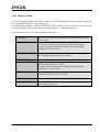
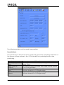
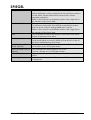
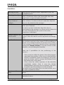
1
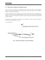
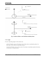
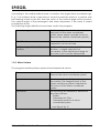
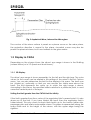
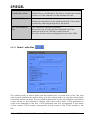
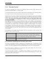
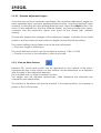
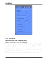
CATIA ® Software
SPIEGEL
User manual
SPIEGEL
1
General
1.1
Norms
3
1.1.1
ECE-R 46 Norm
4
1.1.2
US – Norm FMVSS111
6
1.2
Position of the Vehicle and the Mirror
7
1.2.1
Mirror Plane and Mirror Coordinatesystem
7
1.2.2
Angle
9
1.2.3
Mirror Surface
1.3
10
Display in CATIA
11
1.3.1
3D Display
11
1.3.2
Views in CATIA
12
2
Instruction Manual
13
2.1
The MIRROR-Program for CATIA ® from TransCAT
13
2.2
Starting the Program
14
2.2.1
Data
14
2.2.2
Design/Display Contours
19
2.2.3
Viewing the Mirror Surface
21
2.2.4
Adjusting the Mirrors
24
2.2.5
Calculate Occultation
25
3
3.1
Appendix
29
Troubleshooting
© TransCAT GmbH & Co. KG
29
2
CATIA Software
SPIEGEL
1 General
The Spiegel-Program calculates the field of view with interior and exterior mirrors,
with the goal to design mirrors that meet the requirements of not only the ECE-R 46
Norm, (for automobiles as well as trucks), but also fulfill the conditions of the USNorm FMVSS111.
1.1 Norms
Within the respective Norms the legislator prescribes the particular area at the rear
of the vehicle that has to be visible through each mirror.
The texts of the Norms refer to fields on the tracks that are limited by the horizon at
their rears, (exceptions to this are wide angle mirrors on trucks, and ground mirrors).
However this procedure is not feasible for practical and mathematical trials. This is
why the TÜV (German Safety Standards Authority) examines and measures the
driver’s percentile eye range on a vertical screen.
The trial process conducted by the TÜV runs as following:
-
Dot-shaped sources of light represent the points of the driver’s eyes.
-
A mirror projects the beams of light onto a vertical screen at the rear of the
vehicle.
-
There is a rectangular regulatory area marked on the screen that has to be
illuminated.
The program simulates this process that can be very costly. With the aide of this
program, the user can easily test how certain parameters effect the degree of
illumination.
In this case, the program differentiates between the automobile Norm ECE-Screen
and ECE-Road, as well as US-Screen and US-Road. The TÜV trials are simulated
during the Screen-Norms, and the driver’s percentile eye range within the
regulatory area can be calculated. The Road-Norms simulate the driver’s eye
range on the track, and the contours deriving from the driver’s eye range can be
calculated, however without percentile details.
Amongst other things, the Norms determine, where the points of the driver’s eyes
lie, the distance between the regulatory area and the vehicle, and the size of the
regulatory field on the screen and on the tracks respectively.
© TransCAT GmbH & Co. KG
3
CATIA Software
SPIEGEL
Refer to the Norm-texts concerning the minimum mirror size and the required
degree of illumination.
The data used by the program is described as following:
1.1.1 ECE-R 46 Norm
The location of the point of the eyes in the ECE-Norm is defined by the location of
the seating-reference-point and the position of the vehicle on the track (e.g. by
spring-deflection).
1.1.1.1 Passenger Vehicles
The location and the size of the regulatory field on the screen can be derived by
the following table:
Type of Mirror
Interior Mirror
Exterior Mirror
Driver side
Exterior Mirror
Passenger side
Position
Size
60 m behind
Height: upper mirror point above the
the point of the lane
eyes.
Width: from 10 m to the left of, up to 10 m
to the right of the center of the vehicle
10 m behind
Height: upper mirror point above the
the points of
track
the eyes
Width: 2.5 m beyond the point of the
vehicle’s point of greatest width
20 m behind
Height: upper mirror point above the
the points of
lane
the eyes
Width: 4 m beyond the vehicle’s point of
greatest width
The height of the field is re-calculated when adjustments are made to the mirrors.
(upper mirror point above the lane).
While height can be ignored, the position of the regulatory field on the track is
identical in width and location.
1.1.1.2 Trucks
Displays of the eye range for the ECE-Truck Norm solely take place in designated
space-areas. The regulatory areas in use,are similar to those used by
DaimlerChrysler AG.
© TransCAT GmbH & Co. KG
4
CATIA Software
SPIEGEL
Type
Exterior Mirror
Driver Side
Position
10 m behind the points of the
eyes
Main Mirror
Passenger Side
4 m behind the points of the
eyes
Wide Angle
Mirror
Passenger Side
3 m behind the points of the
eyes
Ground Mrror
Passenger Side
Forwards Limitation:Depends
upon the forward most point of
the vehicle.
The vertical plane limits the
field to the front, and lies 1 m in
front of the points of the eyes. If
the vertical plane lies closer
than 1 m in front of the points
of the eyes, then this plane is
considered.
© TransCAT GmbH & Co. KG
5
Size
Height: upper mirror point
above the track
Width: 2.5 m beyond the
vehicle’s point of greatest
width
Height : The field is „folded“ at
a distance of 30 m, the height
corresponds to the upper most
mirror point above the track
Width: At 4 m, the width of the
field is 0.75 m, if measured from
the vehicle’s point of greatest
width. The field widens in linear
progression until it reaches a
distance of 30 m behind the
points of the eyes and a width
of 3.5 m
Height: The field is limited at a
distance of 25 m behind the
points of the eyes and lies on
the track.
Width: Measuring from the
point of the vehicle’s greatest
width, the width of the field is
2.5 m. The field widens in linear
progression until it reaches a
distance of 15 m behind the
points of the eyes and a width
of 12.5 m.
The fied lies on the track.
Width:
Add 0.2 m to the greatest
width of the driver’s cab, and 1
m beyond that point.
CATIA Software
SPIEGEL
1.1.2 US – Norm FMVSS111
The Position of the points of the eyes in the US-Norm FMVSS111 depends upon the
seating-reference-point, the position of the vehicle on the track (spring deflection)
and two more parameters, namely the so-called H-Point-Travel and the Torso-Line,
or the degree at which the driver is “leaning” into the seat.
These parameters have been standardized at the following values:
-
H-Point-Travel: 165 mm (inconvenient seat position)
Torso-Line:
25 degrees
Depending on the position of the mirror, it is presumed that a driver will turn his/her
head, and the points of the eyes will no longer be parallel to the vehicle’s axles.
The points of the eyes are re-calculated with each adjustment made to the mirrors
in the program, therefore a head turning can occur, if the given angle described
in the Norm is exceeded.
The calculation of the points of the eyes in the US-Norm corresponds to the trials
that the DaimlerChrysler AG conducts.
© TransCAT GmbH & Co. KG
6
CATIA Software
SPIEGEL
The location and size of the regulatory area can be derived from the following
table:
Type of Mirror
Interiror Mirror
Position
61 m behind
the backward
most point of
the vehicle
Exterior Mirror
10.7 m behind
Driver’s Side
the middle
point of the
eyes
Exterior Mirror
10.7 m behind
Passenger’s Side the middle
point of the
eyes
Size
Height: upper mirror point above the track
Width: Is calculated according to the
mirror’s positon to the points of the eyes
Height: upper mirror point above the track
Width: 2.44 m beyond the point of the
vehicle’s greates width
Height: upper mirror point above the track
Width: 2.44 m beyond the point of the
vehicle’s greates width
The height of the field is re-calculated when adjustments are made to the mirrors.
(upper mirror point above the lane).
While height can be ignored, the position of the regulatory area on the track is
identical in width and location.
1.2 Position of the Vehicle and the Mirror
The following data describes the mirrors:
-
planar or spherical Contour in the actual CATIA-model
-
The point of rotation of the mirror
-
The mirror’s distance to the point of rotation
-
Parameters that define the shape of the glass (for spherical and aspherical
mirrors)
Additionally the Norm requires certain data about the vehicle, which must be
given, such as the width of the vehicle, as well as data that reveals the position of
the vehicle on the track.
-> go to Chapter Instruction Manual Data.
The reference-axis-system (vehicle-coordinating-system) of the Program is the
CATIA-Axissystem *AXS1 of the current model. The x-axis must be running opposite
the driving direction, with the z-axis pointing upwards.
see Figure fig.2
© TransCAT GmbH & Co. KG
7
CATIA Software
SPIEGEL
1.2.1 Mirror Plane and Mirror-Coordinate-System
In the case of a spherical, or aspherical mirror, the mirror plane is the tangent
plane on the mirror at the point at which the mirror’s surface and the mirror’s
center of rotation would meet
At the zero-position, the xy-plane of the mirror-coordinate-system is parallel to the
yz-plane of the vehicle-coordinate-system. The source of the mirror-coordinating
system is the point at which the mirror’s center of rotation and the mirror plane
would connect.
The plane at zero-position is parallel to the xy-plane of the vehicle-coordinatesystem for groundmirrors on trucks.
-> see Figure fig.1
Fig. 1 Position of the Mirror’s Center of Rotation
© TransCAT GmbH & Co. KG
8
CATIA Software
SPIEGEL
Fig. 2 Position of Mirror- and Vehiclecoordinatesystem
1.2.2 Angle
The two adjusting angles of the mirrors are:
-
vertical: Rotation around the fixed y-axis of the mirror-coordinate-system (i. e.
the z-axis of the vehicle-coordinate-system).
-
horizontal: Rotation around the x-axis of the mirror-coordinate-system that does
not remain in a fixed position.
© TransCAT GmbH & Co. KG
9
CATIA Software
SPIEGEL
According to the mathematical sense of rotation, the angles have a prefixed sign.
E. g., if an exterior driver’s side mirror is turned toward the driver in a vehicle with
the steering wheel on the left, then the value of the vertical angle will be positive.
The vertical angle of the passenger’s side mirror decreases, if the mirror is turned
towards the driver.
The following angle definitions have been used in the program:
Absolute Angle
Rotation of the mirror to the absolute
zero-point of the mirror-coordinatesystem (mirror plane is parallel to the yzplane of the vehicle-coordinate-system).
Initial Situation
The zero-position for the mirror’s
suspension can be set here
Relative Angle to the Initial
Situation
Rotation of the mirror towards initial
situation -> angles need not be
converted, so the adjustment range for
the mirror’s joint can be determined
1.2.3 Mirror Surface
The program handles planar, spherical and aspherical mirrors.
Planar
The mirror surface is identical to the xyplane of the mirror-coordinate-system.
Spherical
The mirror surface is finitely determined
via a radius. The tangent point of the
sphere and the xy-plane is identical to
the source of the mirror-coordinatesystem.
The following are needed to determine
the mirror surface:
- Radius
- Parameter for Glas
- Parameter position of mirrorcoordinate-system
Aspherical
(-> see Figure fig. 3)
© TransCAT GmbH & Co. KG
10
CATIA Software
SPIEGEL
Fig. 3 Aspherical Mirror, Intersection Mirrorglass
The contour of the mirror surface is preset as a planar curve on the mirror plane,
the projection direction is normal to the plane. Arcuated curves may also be
preset for spherical mirrors, but it must adhere to the given radius.
1.3 Display in CATIA
Depending on the chosen Norm, the driver’s eye range is shown in the Drafting
(screen Norms) or in 3 D (track and truck Norms).
1.3.1 3D Display
The driver’s eye range is shown separately for the left and the right eye. The color
values for the curves can be altered in the settings of the mirror in the Set Options
menu. You can also determine the limit for the display in this menu. The track can
be „folded up“ optionally, so that you can monitor the visible area above the
track. The limit represents the value up to which the sight range is drawn.
According to the Norms, the specified data is relative to a particular point, in most
cases the centroid point of the eyes.
Setting the Limit greater than the CATIA-Limit for Infinity.
If the limit is greater than the x-value of the regulatory field’s nearest point, it is also
drawn up to the limit. If you have folded the track, then the regulatory field is
folded aswell. This only counts for track that stretch up to the horizon (driver side,
passenger side and interior automobile mirrors. The plane is represented along the
entire width and to the height of the mirrors, with the upper edge being the
sightline.
© TransCAT GmbH & Co. KG
11
CATIA Software
SPIEGEL
1.3.2 Views in CATIA
CATIA-Drafting displays the eye range for ECE-Passenge Vehicle-Screen and the
US- Passenge Vehicle -Screen Norms.
The program creates a draft TCMIRROR in the current CATIA-model, as soon as the
program displays the eye range, or switches to it, if already present.
The following views can be created if needed:
TCFAHRER
TCFAHRERSPH
Range is shown on the screen with the exterior mirror
driver side.
For an aspherical exterior mirror driver side
-> View is shown with spherical part of the mirror.
Is only created when the spherical part is being
examined -> see Data.
TCFAHRERKONTUR
The contour of the driver side mirror -> is created in
the Programmpunkt show contour
TCBEIFAHRER
TCBEIFAHRERSPH
View onto the screen with passenger side mirror.
For an aspherical passenger side mirror -> eye rabge
with spherical part of mirror.
Is only created when the spherical part is being
examined -> see Data.
TCBEIFAHRERKONT
Contour of passenger side mirror -> is created in the
Programmpunkt show contour.
TCINNEN
View on screen with interior mirror.
TCINNENKONTUR
Contour of interior mirror -> is created in the Program
point show contour.
© TransCAT GmbH & Co. KG
12
CATIA Software
SPIEGEL
2 Instruction Manual
2.1 The SPIEGEL-Program for CATIA ® from
TransCAT GmbH & Co. KG
The program is started in the interactive CATIA. Entries occur in a Motif-process,
that runs simultaneously with CATIA.
Please note the following points:
-
The motive windows always appear in the foreground, in front of the CATIA
window. If one of the edges of the motive windows exceeds the size of the
desktop, then the window is no longer automatically displayed in the
foreground.
-
The cursor-symbol represented by a sand clock is active in the CATIA window
during the program-run.
-
Selecting is possible in CATIA, but the appropriate button must be pushed first,
e. g.: SEL Seating-reference-point. The cursor symbol changes to its normal
condition for the selection. The motive window may fade into the background,
but is re-activated after the selection is made. When multiple selections can be
made, e. g. chosing covering elements, the selection is finished with YES.
-
The program can be shut down with the CATIA-Interrupt selection, but data is
not stored.
-
Like other IUA-programs,CATIA functions should not be recalled while the
program is running. They are the equivalent to Interrupt. But, Interrupt is not
executed until the next selection, or the end of the program.
-
A buffer-regeneration can be recalled in the MIRROR-windows for the space
area with the „BR“-button.
© TransCAT GmbH & Co. KG
13
CATIA Software
SPIEGEL
2.2 Starting the Program
Either start the program with the command “/m Mirror” in the command line, or
through the CATIA menu bar, depending on what the settings are.
The program cannot be started in the 2D-Space-Mode.
After the start, the window for entering data pops up.
If at hand, the last user-related settings are loaded (file MIRROR.usr also see Data > read files.
The program consists of the following menu points that are referred to above the
buttons on the upper part of the window:
-
End program
Data
Display contour
View window surface
Adjust mirrors
Calculate coverage
Read file (in data window)
Write file (in data window)
Helpmenu
2.2.1 Data
The desired mirror and vehicle adjustments are made and a Norm is chosen in this
window.
© TransCAT GmbH & Co. KG
14
CATIA Software
SPIEGEL
The following entries must be made/ are possible:
Panel Vehicle:
The positioning on the track can be made with geometric presettings (Selection of
the lane or runway surface in the CATIA-Model) or by entering the structure
positioning, .
Selecting a Norm
Selecting between ECE- or US-Norm.
Selecting a type of
Mirror
Mirror’s Point of
Rotation
Seating-ReferencePoint
Identifier Track
surface
Selecting between driver side, passenger side and
interior mirror.
Point around which the mirror can rotate can be chosen
as a CATIA-geometry.
Point that determines driver’s positon.
Can be chosen as a CATIA-geometry.
Only needed for geometric presettings for the lane.
Can be chosen as a CATIA-geometry.
© TransCAT GmbH & Co. KG
15
CATIA Software
SPIEGEL
Spring Deflection
Only needed for the presettings of the lane with data.
Spring deflection values determine the vehicles position
on the track. Spring deflection has positive values,
opposite negative.
Refer to the vehicle coordinate system, the origin lies in
the center of the front axle.
Structure Position
Only needed for the presettings of the track with data.
The distance between the vehicle coordinate system
and the track without spring deflection values.
Refer to the vehicle coordinate system, the origin lies in
the center of the front axle.
Axle
Only needed for the presettings of the track with data.
Distance between the axles.
Width
Entire width of the vehicle.
For ground-lights on trucks: Width of the driver’s cab at
the point described by the Norm.
Most Backward Point Only required for the interior mirror in the US-Norm. Can
of the Vehicle
be chosen as a CATIA-geometry.
Most Forward Point of Only required for ground-lights on trucks.
Vehicle
Can be chosen as a CATIA-geometry.
H-Point-Travel
Only required for points of the eyes in US-Norm (default
165m).
Seat Angle
Only required for points of the eyes in US-Norm (default
25 degrees).
© TransCAT GmbH & Co. KG
16
CATIA Software
SPIEGEL
Panel Mirror:
Selecting a Norm
Selecting Mirror Type
Distance between
Mirror’s Point of
Rotation
Selecting the different Norms, dependent upon the
available license.
Selecting between driver side, passenger side, or interior
mirror, or between driver side, passenger side wide
angle mirror, or ground mirror for trucks.
Distance between mirror’s point of rotation and the
mirror surface. If a mirror contour is selected, then this
value is calculated by the program.
Initial Position
Vertical and horizontal angle of the mirror at the desired
initial (see General).
If a mirror contour is selected, then this value is
calculated by the program, but they can be altered by
the user. Generally the zero-point of the mirror
suspension is displayed.
Relative Angle to the
Initial Position
If the desired mirror position differs from the initial
position, then the mirrors can be adjusted accordingly
here.
Identifier Contour
CATIA mirror contour identifier.
The contour must be in the current CATIA-model as a
planar, or for spherical mirrors as a bent curve (*CRV),
if the contour of the mirror should not be calculated
(Menupoint: Display Contour), it can be chosen under
selection, or by entering the identifier.
There are 2 possibilities for the positioning of the
contour:
If the curve lies within the space, then the program
calculates the position of the curve in the absolute
vehicle coordinate system according to the given
point of rotation, and it conveys the distance and
the initial point of the mirror .
If the curve lies within xy-plane of the absolute
coordinate system, then it can be chosen
independently from the point of rotation. The point
of rotation and the distance must be entered.
The radius must be entered for a curved contour, as in
the case of spherical mirrors.
Selecting between planar, spherical and aspherical
mirrors
-
Curvature of the
Mirror
Radius
Radius of the mirror surface: required for spherical and
aspherical mirrors.
© TransCAT GmbH & Co. KG
17
CATIA Software
SPIEGEL
Position of
Coordinate system
Only applies to aspherical mirrors.
Defines the x-coordinate in the mirror coordinate system
(when y=0 ) the transition to the aspherical part.
Parameter Glass
Only applies to aspherical mirrors.
Defines the transition to the aspherical part of the glass.
Is preset by selecting the glass of the mirror.
Only Use Spherical
Part
Only applies to aspherical mirrors.
Allows the user to only use the spherical part. The
spherical part must fulfill the current Norms.
The view on the screen is displayed in an extra VIEW.
2.2.1.1 Read / write files
The vehicle and/ or mirror data can be written into, or read from a file. The user
can choose whether the entire data, only the vehicle data, or only the mirror data,
should be written or read. The occultation elements for the occultation calculation
is also written in the selections vehicle data and entire data. CATIA-geometry is
used as an identifier in the files. CATIA elements are only recognized, if the name
of the current CATIA-model corresponds to the name of the CATIA-model in the
file.
© TransCAT GmbH & Co. KG
18
CATIA Software
SPIEGEL
The data is in the inventory that is displayed in the declaration file. (see
Administration).
The SPIEGEL.usr file that is read at the beginning of the program is generally kept in
a separate inventory (also displayed in the declaration file)
2.2.2 Display Contour
Can only be selected for the ECE- and US-Automobile-Screen Norms.
The minimum required contour for covering the regulatory field, can be calculated
in this menu point. Additionally which adjustment angles are required, so that
different drivers’ positions are covered.
© TransCAT GmbH & Co. KG
19
CATIA Software
SPIEGEL
2.2.2.1 Calculate Contour
In order to calculate the contour for a different driver position, then data can be
altered in the SRP-panel, i.e. screen/wall.
The seating-reference-point is either determined by selecting or by entering values.
The original values for the other program points are not changed.
Furthermore the screen’s height and width can be changed to get an accordingly
larger contour. The lower point of the regulatory field showing towards the vehicle
remains the same (for interior mirrors the center point of the lower edge of the
screen.) The screen that is displayed in CATIA is always the Regulatory Field that
the Norms prescribe!
The height of the screen must be determined first, as the height of the regulatory
field depends upon the upward most point of the mirror (as a standard the height
of the screen = z-coordinate of the point of rotation + 45 mm). The value can be
changed in the Screen Panel, with Mirror Height or Screen Height. The entered
mirror height is the initial point, the contour is calculated so that the given screen is
covered. The contour can either be greater or less than the given mirror height. If
the initial height is set too low, then it may occur that not all of the regulatory field
is illuminated.
The position of the mirror must be given for the calculation of the contour. The
program offers 2 options for this:
- Calculate Angle:
The angles are calculated so that the sightline hits the
center of the screen from the centers of the eyellipses
over the center of the mirror (center point of the point of
rotation’s intersection with the mirror surface).
- Initial position:
The initial point that is set in the data window is used as
the position of the mirror.
The calculation is initiated with the Calculate Contour-button.
The newly calculated contour is displayed in a separate view. Coordinates of the
contour are displayed in the mirror coordinate system and the vehicle coordinate
system. The values represent the according planar contour on the mirror plane.
The CATIA-screen is divided into 2 segments, the upper dislays the view on the
screen, the lower displays the contour.
If the environment variable TC_MIRROR_ONE_SCREEN is set on TRUE, then the
screen is not split. The user can switch back and forth between the 2 views in the
lower part of the motif-window.
© TransCAT GmbH & Co. KG
20
CATIA Software
SPIEGEL
2.2.2.2 Examine Adjustment Angles
Once the new contour has been calculated, the necessary adjustment angles for
each separate driver’s position (seating reference point ) can be examined. After
entering, or selecting the new seating refernce point, select the Adjust button. The
mirror is now adjusted so that the extreme beam/ ray turning toward the driver,
connects with the respective upper most point on the screen (self- defined
screen).
The window displays the changes of the adjustment angles, in relation to the initial
position, and the minimum and maximum angles (towars the initial position).
The current setting can be taken over as the new initial point.
-> Take over angle as initial point.
The newly defined contour can be created as a planar *CRV in CATIA.
-> Create a contour in the initial point within the model.
2.2.3 View on Mirror Surface
Random 3D- curves and –points can be displayed on the surface of the mirror.
Therefore the size of the contour on the surface can be examined, or re-adjusted
with the aide of the displayed elements.
This is possible with or without a preset contour.
The angles can be adjusted dynamically, while displayed the elements are
constantly calculated anew.
The surface of the mirror can also be created, in its current position, as a sphere or
plane, in the CATIA-model.
© TransCAT GmbH & Co. KG
21
CATIA Software
SPIEGEL
2.2.3.1 Panel Elements
Displaying Elements on the Surface of the Mirrror:
Random 3D-curves and –points can be displayed.
The elements can be shown directly, or directly. Directly means that the sightline
running between the eye and the surface determine the display of the elements.
Indirect means that the elements are displayed according to the sightlines
reflected off of the mirror surface.
The CATIA-color, and whether it has been calculated for one eye, or both eyes,
can be chosen for every single element.
The selected elements are also stored, whenever the vehicle data is stored.
© TransCAT GmbH & Co. KG
22
CATIA Software
SPIEGEL
Display Regulatory Field:
The regulatory field that the Norm requires can also be show in the mirror. For this
the actual field is taken, regardless of the display (3D: Limit and fold).
The figure resembles a triangle for the Passenger Car-Norms, as the limiting points
correspond to one point on the mirror suface in infinity.
Display Contour:
The selected contour is displayed in the current position, when this button is
selected and there is a mirror contour at hand. If a planar curve has been chosen
as a contour, then the tilted contour is planar on the current mirror plane.
Create Element in the Model:
This button fixes the elements permanently into the model (the testlines are not
created here).
Edit Sphere/Plane:
The mirror surface for the spherical and planar parts in the current position, can be
created.
2.2.3.2 Adjust Panel
The position of the mirror can be adjusted in this panel. This either occurs with the
arrow keys, or by making angle entries in the according input fields (analogous to
adjust mirrors).
The mirror can also be adjusted, by presetting a point, geometrical or with data.
The mirror is adjusted so that the selected point of the chosen eye, can be seen in
the center of the mirror (line adjoining point of rotation and surface of mirror). The
mirror is turned so that the chosen point in the center of the mirror is seen with the
selected eye (point where point of rotation adjoins mirror surface). If both eyes
have been selected, then the middle eye is looked upon.
The elements at display, are recalculated whenever changes are made. The
duration of the calculation depends upon the complexity of the surface and the
number of curves that are to be calculated.
Display Testlines:
If a contour has been entered, then 4 testlines and the points of the eyes are
edited, analogous to the menu point adjust mirrors.
© TransCAT GmbH & Co. KG
23
CATIA Software
SPIEGEL
2.2.4 Adjust Mirrors
Here, the mirror is brought into the desired position, either to calculate the
coverage, or to determine the required adjustment area.
If the eye range is displayed in a drafting (passenger car- screen), then the CATIA
screen is split into 3 windows, where the upper window displays the range on the
regulatory field. The lower windows represent a side and plan view of the eyellipse.
If the environment variable TC_MIRROR_ONE_SCREEN is set on TRUE, then the
screen is not split. The user can switch back and forth between the 2 windows in
the lower part of the motif window.
The track, the 4 testlines and the points of the eyes are edited temporarily in CATIA
3D. The elements are deleted, if another menu point is selected, or if the program
is aborted (,if not edited permanently in the model -> see below).
The 4 sightlines derive from the extreme points of the contour and the sightlines
from the respectively positioned eye point. The lines for the upper and lower
extreme points are yellow, the lines for the left and right extreme points are green.
© TransCAT GmbH & Co. KG
24
CATIA Software
SPIEGEL
2.2.4.1 Setting
The arrow keys represent the viewing direction onto the mirror, the view contains
the backward going perspective onto the regulatory field. The mirror on the screen
moves left, if the right arrow key is pressed.
The adjustment is made with the given settings for the delta angle.
The adjustment angles can be altered directly by making entries in the input fields.
Besides adjusting the settings manually, automatic adsjustments can also be
made.
Extreme
Ray/Beam :
Normal:
Adjusts the mirror so that the interior extreme beam lies
parallel to the middle plane of the vehicle, the upper
extreme line lies parallel to the track.
Adjusts the mirror according to the normal in the
approximate center of the mirror and the center of the
screen.
2.2.4.2 Output Angle
The output fields Angle to Initial Position show the difference of the current angle to
the initial position of the mirror (defined in the Data window). The absolute angles
refer to the position of the mirror in relation to the yz-plane of the vehicle.
These four windows may also be used to bring the mirror in the desired position.
The current test sightlines, the points of the eyes and the track are edited with the
Edit Test Sightlines and Points of Eyes in the Model button. If this function is
executed numerous times in a model, then numerous points of eyes and tracks will
exist in the same model.
2.2.5 Calculate Occultation
This point is there to calculate the occultation caused by the vehicle’s geometry.
The compliance to the according Norm can be examined.
The percentile display of the occulatation is only possible for the ECE-Passenger
Vehicle-Screen and Us-Passenger Vehicle-Screen Norms. The resulting curves for
the eyes are edited for the Norms that display the eye range in the space area on
the track.
© TransCAT GmbH & Co. KG
25
CATIA Software
SPIEGEL
The occulatation geometry has to be entered in form curves in CATIA. The
contours need not be closed. They will be treated as if they are closed over the
initail and end points during the calculation.
Then the program will examine if the lines going from the eyes to the mirror, i. e.
being reflected off of the mirror, hit the contours.
The program alters Non-planar curves for the calculation of their compensation
plane. Therefore they must completely lie between the mirror and screen (for
direct coverage), i. e. between mirror and points of eyes (for indirect coverage).
© TransCAT GmbH & Co. KG
26
CATIA Software
SPIEGEL
The contours are sub-divided into four kinds of occultation:
Direct interior occultation
Geometry
Direct exterior occultation
Geometry
Indirect interior occultation
Geometry
Indirect exterior-covering
Geometry
Occultation of sightline of the eyes to the
mirror by the contours.
Occultation occurs by the interior area,
e.g. x-intersections for exterior mirrors.
Occultation of the sightline of the eyes to
the mirror by the contours.
Occultation occurs by the exterior area,
e.g. intersections through the casing of the
mirror.
Occultation of the sightline leaving the
mirror by the contours.
Occultation occurs by the interior area,
e.g. x-intersections for exterior mirrors.
Occultation of the sightline leaving the
mirror by the contours.
Occultation occurs by the exterior area,
e.g. Limitation of the rear window for
interior mirrors.
The curves can be selected in CATIA and are aranged to the currently selected
button.
An intersection cannot be directly (indirectly) interior- and exterior-occultating at
the same time.
According to the setting of the button, the selected curves are displayed in the
highlight-mode.
The contours can also be chosen from the textfield in the CATIA-multiselect.
If *CRV is chosen here, then the contour of the mirror is possibly regarded as a
occultation curve.
© TransCAT GmbH & Co. KG
27
CATIA Software
SPIEGEL
The Calculation is initiated with the COMPUTE button.
The duration of the calculation depends upon the number of occultation curves
as well as the size of the eye range (eyellipse). This means that the calculation for a
spherical mirror lasts longer than for a planar mirror with the same contours.
Output:
Only for the ECE-Passenger Vehicle-Screen and US-Passenger Vehicle-Screen
Norms.
Occultation Regulatory Field
Occultation Eye Range
The computated occultation of the regulatory
field defined by the Norm.
Dependent upon the Norm, it may not exceed a
certain value. (E.g. for the EWG-Norm exterior
mirror 10 %).
The computated occultation of the eye range,
the area the mirror illuminates on the screen
without covering geometry.
The selected contours can be stored in a file (vehicle data or entire data), and
they can be read from such. To do so, one must switch over to the Data window,
and either select Read Data or Write Data.
The contours are stored in the MIRROR.usr file when the program is aborted, and
are recalled when the program is restarted, that is, if the same CATIA model is
being used.
© TransCAT GmbH & Co. KG
28
CATIA Software
SPIEGEL
3 Appendix
3.1 Troubleshooting
Error messages generally appear in a motif window. Additonal information is
partially shown on the alpha screen.
System problems:
CATIA-crash with U0851 or
CATIA-Errors, that can occur depending on the
Uxxx as soon as the CATIACATIA-Version and Operating system, when the
window is split (Set mirrors or Program splits the screen.
display contours)
By setting the environment variable
TC_MIRROR_ONE_SCREEN to TRUE (in the script
spiegel), the screen is not split by the program. The
user can choose the desired view in the according
windows.
CATIA-crash -> Motif-Process If the reason for the system crash is unclear then call
cannot be shut down
TransCAT GmbH & Co. KG (Tel.:0049 / 721/97043-75).
The motif process might have to be shut down at
system level. Please clarify with the systems
administrator if the following can be done:
With the ps –e | grep SPIEGELM command, you
receivethe process ID of the motif process, e.g.
13635 ? 0:00 SPIEGELM
With kill –9 13635 the process is terminated.
Motif-window disappears
The motif window is not in the foreground during the
selection in CATIA, but reappears in the foreground
after the selection
Minimize the CATIA-window and examine, if the
window exceeds the desktop.
Error message:
No more actions possible
with CATIA
© TransCAT GmbH & Co. KG
Semaphoren, that guide the transmission have been
deleted.
Is not allowed to happen during normal execution!
Shut down program with CATIA-interrupt.
29
CATIA Software
SPIEGEL
Problem during Application:
Problems while drawing
contours
CATIA-Elements exceed the
visible area in display with
view on the screen
Check if angle setting is sensible. Is the screen within
the eye range in the current setting?
The regulatory field can be very wide, especially for
interior mirrors. The scaling factor for this view can
be set in the declarations file.
Decrease the scaling factor in MIRROR.dcls.
Selected mirror contour is
not planar
Be sure that the curve is planar by, e.g. projection
onto the plane.
The following message
appears on the alpha
screen:
... GIDSHA ... crossing not
allowed...
Appears, when a CATIA-SHAPE intersects with itself.
If the error occurs while the eye range is being
created on the screen -> Check, if the starting point
and end point of the contour curve intersect.
If the error occurs while the occultation is being
calculated -> check, if the occultation curves can
be closed sensibly with starting and end points.
Curves that are too sharp, or that are degenerated
to lines, can be the cause.
Could be that the mirror contour has been chosen
as an interior- occultation curve, or the entire eye
range is occultated.
Error message during the
calculation of the
occultation:
Cannot find a closed
contour on the screen.
© TransCAT GmbH & Co. KG
30
CATIA Software