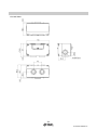
1
No.EX※※-OMB0014-G PRODUCT NAME SI unit for CC-Link MODEL / Series / Product Number EX12#-SMJ1 Series Table of Contents Safety Instructions 2 Model Indication and How to Order 8 Summary of Product parts 9 Definition and terminology 11 Mounting and Installation 12 Communication wiring 12 Power supply wiring 14 Settings 15 Maintenance 19 Troubleshooting 21 Specification 31 Specifications 31 Dimensions 32 -1No.EX※※-OMB0014-G Safety Instructions These safety instructions are intended to prevent hazardous situations and/or equipment damage. These instructions indicate the level of potential hazard with the labels of "Caution", "Warning" or "Danger". They are all important notes for safety and must be followed in addition to International standards (ISO/IEC) 1) and other safety regulations. 1) ISO 4414: Pneumatic fluid power -- General rules relating to systems. ISO 4413: Hydraulic fluid power -- General rules relating to systems. IEC 60204-1: Safety of machinery -- Electrical equipment of machines. (Part 1: General requirements) ISO 10218-1992: Manipulating industrial robots -Safety. etc. Caution : Warning : Danger : CAUTION indicates a hazard with a low level of risk which, if not avoided, could result in minor or moderate injury. WARNING indicates a hazard with a medium level of risk which, if not avoided, could result in death or serious injury. DANGER indicates a hazard with a high level of risk which, if not avoided, will result in death or serious injury. Warning 1. The compatibility of the product is the responsibility of the person who designs the equipment or decides its specifications. Since the product specified here is used under various operating conditions, its compatibility with specific equipment must be decided by the person who designs the equipment or decides its specifications based on necessary analysis and test results. The expected performance and safety assurance of the equipment will be the responsibility of the person who has determined its compatibility with the product. This person should also continuously review all specifications of the product referring to its latest catalogue information, with a view to giving due consideration to any possibility of equipment failure when configuring the equipment. 2. Only personnel with appropriate training should operate machinery and equipment. The product specified here may become unsafe if handled incorrectly. The assembly, operation and maintenance of machines or equipment including our products must be performed by an operator who is appropriately trained and experienced. 3. Do not service or attempt to remove product and machinery/equipment until safety is confirmed. 1. The inspection and maintenance of machinery/equipment should only be performed after measures to prevent falling or runaway of the driven objects have been confirmed. 2. When the product is to be removed, confirm that the safety measures as mentioned above are implemented and the power from any appropriate source is cut, and read and understand the specific product precautions of all relevant products carefully. 3. Before machinery/equipment is restarted, take measures to prevent unexpected operation and malfunction. 4. Contact SMC beforehand and take special consideration of safety measures if the product is to be used in any of the following conditions. 1. Conditions and environments outside of the given specifications, or use outdoors or in a place exposed to direct sunlight. 2. Installation on equipment in conjunction with atomic energy, railways, air navigation, space, shipping, vehicles, military, medical treatment, combustion and recreation, or equipment in contact with food and beverages, emergency stop circuits, clutch and brake circuits in press applications, safety equipment or other applications unsuitable for the standard specifications described in the product catalogue. 3. An application which could have negative effects on people, property, or animals requiring special safety analysis. 4. Use in an interlock circuit, which requires the provision of double interlock for possible failure by using a mechanical protective function, and periodical checks to confirm proper operation. -2No.EX※※-OMB0014-G Caution The product is provided for use in manufacturing industries. The product herein described is basically provided for peaceful use in manufacturing industries. If considering using the product in other industries, consult SMC beforehand and exchange specifications or a contract if necessary. If anything is unclear, contact your nearest sales branch. Limited warranty and Disclaimer/Compliance Requirements The product used is subject to the following "Limited warranty and Disclaimer" and "Compliance Requirements". Read and accept them before using the product. Limited warranty and Disclaimer 1. The warranty period of the product is 1 year in service or 1.5 years after the product is delivered, whichever is first. 2) Also, the product may have specified durability, running distance or replacement parts. Please consult your nearest sales branch. 2. For any failure or damage reported within the warranty period which is clearly our responsibility, a replacement product or necessary parts will be provided. This limited warranty applies only to our product independently, and not to any other damage incurred due to the failure of the product. 3. Prior to using SMC products, please read and understand the warranty terms and disclaimers noted in the specified catalogue for the particular products. 2) Vacuum pads are excluded from this 1 year warranty. A vacuum pad is a consumable part, so it is warranted for a year after it is delivered. Also, even within the warranty period, the wear of a product due to the use of the vacuum pad or failure due to the deterioration of rubber material are not covered by the limited warranty. Compliance Requirements 1. The use of SMC products with production equipment for the manufacture of weapons of mass destruction (WMD) or any other weapon is strictly prohibited. 2. The exports of SMC products or technology from one country to another are governed by the relevant security laws and regulation of the countries involved in the transaction. Prior to the shipment of a SMC product to another country, assure that all local rules governing that export are known and followed. -3No.EX※※-OMB0014-G Operator This operation manual is intended for those who have knowledge of machinery using pneumatic equipment, and have sufficient knowledge of assembly, operation and maintenance of such equipment. Only those persons are allowed to perform assembly, operation and maintenance. Read and understand this operation manual carefully before assembling, operating or providing maintenance to the product. ■Safety Instructions Warning ■Do not disassemble, modify (including the replacement of the circuit board) or repair the product. Do not use the components other than the specified components. An injury or failure can result. ■Do not operate the product outside of the specifications. Do not use for flammable or harmful fluids. Fire, malfunction, or damage to the product can result. Verify the specifications before use. ■Do not operate in an atmosphere containing flammable or explosive gases. Fire or an explosion can result. This product is not designed to be explosion proof. ■If using the product in an interlocking circuit: •Provide a double interlocking system, for example a mechanical system. •Check the product regularly for proper operation. Otherwise malfunction can result, causing an accident. ■The following instructions must be followed during maintenance: •Turn off the power supply. •Stop the air supply, exhaust the residual pressure and verify that the air is released before performing maintenance. Otherwise an injury can result. -4No.EX※※-OMB0014-G Caution ■After maintenance is complete, perform appropriate functional inspections. Stop operation if the equipment does not function properly. Safety cannot be assured in the case of unexpected malfunction. ■Provide grounding to assure the safety and noise resistance of the Serial System. Individual grounding should be provided close to the product with a short cable. ■NOTE ○Follow the instructions given below when designing, selecting and handling the product. ●The instructions on design and selection (installation, wiring, environment, adjustment, operation, maintenance, etc.) described below must also be followed. Product specifications •When conformity to UL is required, the SI unit should be used with a UL1310 Class 2 power supply. •The SI unit is a UL approved product only if they have a mark on the body. •Use the specified voltage. Otherwise failure or malfunction can result. •Reserve a space for maintenance. Allow sufficient space for maintenance when designing the system. •Do not remove any nameplates or labels. This can lead to incorrect maintenance, or misreading of the operation manual, which could cause damage or malfunction to the product. It may also result in non-conformity to safety standards. -5No.EX※※-OMB0014-G ●Product handling Installation •Do not drop, hit or apply excessive shock to the fieldbus system. Otherwise damage to the product can result, causing malfunction. •Tighten to the specified tightening torque. If the tightening torque is exceeded the mounting screws may be broken. •Never mount a product in a location that will be used as a foothold. The product may be damaged if excessive force is applied by stepping or climbing onto it. Wiring •Avoid repeatedly bending or stretching the cables, or placing heavy load on them. Repetitive bending stress or tensile stress can cause breakage of the cable. •Wire correctly. Incorrect wiring can break the product. •Do not perform wiring while the power is on. Otherwise damage to the fieldbus system and/or I/O device can result, causing malfunction. •Do not route wires and cables together with power or high voltage cables. Otherwise the fieldbus system and/or I/O device can malfunction due to interference of noise and surge voltage from power and high voltage cables to the signal line. Route the wires (piping) of the fieldbus system and/or I/O device separately from power or high voltage cables. •Confirm proper insulation of wiring. Poor insulation (interference from another circuit, poor insulation between terminals, etc.) can lead to excess voltage or current being applied to the product, causing damage. •Take appropriate measures against noise, such as using a noise filter, when the fieldbus system is incorporated into equipment. Otherwise noise can cause malfunction. Environment •Select the proper type of protection according to the environment of operation. In case of IP20, avoid use in the place where water and oil scatter. IP65/67 protection is achieved when the following conditions are met. (1) The units are connected properly with fieldbus cable with M12 connector and power cable with M12 (M8) connector. (2) Suitable mounting of each unit and manifold valve. If using in an environment that is exposed to water splashes, please take measures such as using a cover. If the product is to be used in an environment containing oils or chemicals such as coolant or cleaning solvent, even for a short time, it may be adversely affected (damage, malfunction etc.). •Do not use the product in an environment where corrosive gases or fluids could be splashed. Otherwise damage to the product and malfunction can result. •Do not use in an area where surges are generated. If there is equipment which generates a large amount of surge (solenoid type lifter, high frequency induction furnace, motor, etc.) close to the fieldbus system, this may cause deterioration or breakage of the internal circuit of the fieldbus system. Avoid sources of surge generation and crossed lines. •When a surge-generating load such as a relay or solenoid is driven directly, use an fieldbus system with a built-in surge absorbing element. Direct drive of a load generating surge voltage can damage the fieldbus system. •The product is CE marked, but not immune to lightning strikes. Take measures against lightning strikes in the system. •Prevent foreign matter such as remnant of wires from entering the fieldbus system to avoid failure and malfunction. -6No.EX※※-OMB0014-G •Mount the product in a place that is not exposed to vibration or impact. Otherwise failure or malfunction can result. •Do not use the product in an environment that is exposed to temperature cycle. Heat cycles other than ordinary changes in temperature can adversely affect the inside of the product. •Do not expose the product to direct sunlight. If using in a location directly exposed to sunlight, shade the product from the sunlight. Otherwise failure or malfunction can result. •Keep within the specified ambient temperature range. Otherwise malfunction can result. •Do not operate close to a heat source, or in a location exposed to radiant heat. Otherwise malfunction can result. Adjustment and Operation •Set the switches by using a sharp-pointed screwdriver etc. It may damage set switches. •Perform settings suitable for the operating conditions. Incorrect setting can cause operation failure. For details of each setting, refer to page 15 of this manual. •Please refer to the PLC manufacturer's manual etc. for details of programming and addresses. For the PLC protocol and programming refer to the relevant manufacturer's documentation. Maintenance •Turn off the power supply, stop the supplied air, exhaust the residual pressure and verify the release of air before performing maintenance. There is a risk of unexpected malfunction. •Perform regular maintenance and inspections. There is a risk of unexpected malfunction. •After maintenance is complete, perform appropriate functional inspections. Stop operation if the equipment does not function properly. Otherwise safety is not assured due to an unexpected malfunction or incorrect operation. •Do not use solvents such as benzene, thinner etc. to clean the each unit. They could damage the surface of the body and erase the markings on the body. Use a soft cloth to remove stains. For heavy stains, use a cloth soaked with diluted neutral detergent and fully squeezed, then wipe up the stains again with a dry cloth. -7No.EX※※-OMB0014-G Model Indication and How to Order EX120-SMJ 1 Output type 1 16 outputs, NPN (positive common) / sink Fieldbus MJ CC-Link Valve interface EX120 Direct mounting - Plug in EX121 DIN rail mounting - Flat ribbon cable EX122 DIN rail mounting - Plug in EX124U Direct mounting - Plug in (IP65) U side EX124D Direct mounting - Plug in (IP65) D side EX126D Direct mounting - Plug in (IP67) D side -8No.EX※※-OMB0014-G Summary of Product parts •EX120-SMJ1 •EX121-SMJ1 •EX122-SMJ1 -9No.EX※※-OMB0014-G •EX124D/U-SMJ1 •EX126D-SMJ1 -10No.EX※※-OMB0014-G ○Terminal block (with switch cover open) No. Element Description 1 Output connector To connect to the valve manifold 2 LED and Switch cover LED display to indicate the status of the SI unit. Switches for setting the station number and transmission speed. 3 Communication terminals (DA, DB, DG) To connect the CC-Link line with a CC-Link-dedicated cable. 4 Power supply terminals (24 V, 0 V) To supply power to solenoid valves. 5 Power supply terminals (+24 V, 24 G) To supply power for communication. 6 FG terminal To connect to functional ground and to connect the CC-Link cable shield wire. 7 DIN rail mounting bracket For mounting to a DIN rail. Wiring entry (4 places) For connecting the communication and power supply cables to the SI unit. For wiring, use a G1/2 cable gland to achieve enclosure rating of IP65/67. The cable gland should conform to the wire diameter of the communication and power supply cables and should be tightened with the specified torque. Incorrect handling of the wiring entry may allow foreign matter to enter the SI unit, which will lead to a malfunction and damage to the SI unit. Use the waterproof plug assembly (part number: AXT100-B04A) for unused wiring entries. 8 ■Definition and terminology No. Term Definition Number of stations Total number of stations occupied by all slaves connected to the CC-Link network. 2 Station number Numbers assigned to the slave stations, from 1 to 64, with No. 0 assigned to the CC-Link master. Slave stations must be assigned numbers according to the number of occupied stations so they are not duplicated. 3 Slave station General term for any station other than the master station. 4 Number of occupied slaves Number of networked stations in use by a slave. Depending on the data, one to four stations can be set. The remote I/O only occupies one station. 5 Remote I/O A station which can only use digital data. Occupies only one station. (Example: digital units, solenoid valves, sensors, etc) 1 -11No.EX※※-OMB0014-G Mounting and Installation ■Communication wiring The connection between a CC-Link-dedicated cable and an SI unit communication terminal for CC-Link is shown below. (1) Be sure to connect each signal line to its dedicated terminal. (Refer to Fig. 1) Tighten the screws securely with a torque of 0.5 to 0.6 Nm. The terminal screw is an M3 cross head screw. Fig. 1 (2) Be sure to connect a terminating resistor between “DA” and “DB” at both ends of the CC-Link system. (Refer to Fig. 2) Fig. 2 (3) The appropriate terminating resistor varies depending on the CC-Link cable used. (Refer to the table and Fig. 3 below.) Cable type CC-Link dedicated cable CC-Link dedicated cable compatible to Ver.1.10 CC-Link dedicated high performance cable Terminating resistor 110 1/2 W (Brown, Brown, Brown) 130 1/2 W (Brown, Orange, Brown) Fig. 3 Use the correct terminating resistor, available from the manufacturer of the CC-Link master. Use a CC-Link-dedicated cable, or a cable with the same specifications. If a cable with any other specifications is used, normal data transmission cannot be guaranteed. -12No.EX※※-OMB0014-G (4) The CC-Link-dedicated cable’s shield wire (SLD) should be connected to the “FG” terminal of the SI unit. For the EX12#-SMJ1, the "SLD terminal" and "FG terminal" are common. Therefore, connect 3 wires to the "FG Terminal" as shown in Fig. 4. Fig. 4: Wiring to the FG terminal on the SI unit When connecting 3 wires to the “FG terminal”, crimp 2 wires together into one crimped terminal as shown in Fig. 5. Use another crimped terminal for other wires. After crimping, connect wires so that the back of the two crimped terminals face each other. Fig. 5: How to crimp the terminal -13No.EX※※-OMB0014-G ■Power supply wiring Connect the power supply wiring to the solenoid valve power supply terminals and to the SI unit control power supply terminals. Although the power supply consists of two separate systems, it is possible to use either a single power supply or separate power supplies. Be sure to connect the power supply to the correct terminals (Refer to Fig. 6). Tighten the screws securely with a torque of 0.5 to 0.6 Nm. The terminal screw is an M3 cross head screw. Note: Connect the ground terminal to ground. Resistance to ground should be 100 ohms or less. A. Single power supply used B. Dual power supplies used Fig. 6 -14No.EX※※-OMB0014-G Settings ○Display setting Display PW L RUN Meaning LED is ON when the communication power is ON Indicates whether the SI unit is communicating with the master station correctly. LED is ON when the SI unit is receiving normal data from the master station. LED is OFF during time-out. SD LED is ON when data is being sent. RD LED is ON when data is being received. L ERR. LED is ON during communication errors (CRC errors). LED is OFF during time-out (L RUN LED is also OFF). LED is ON during station number setting and communication speed setting errors (the LED will turn off when the setting has been corrected and power has been restored). LED flashes when the station number or communication speed settings have changed during communication (the L RUN LED will turn on and the SI unit will operate according to the new settings once power is restored). If the data link is normal, “PW”, “L RUN”, “SD”, and “RD” LED's will be ON. -15No.EX※※-OMB0014-G ○Switch setting The setting for the station number and communication speed can be carried out using the rotary switches under the LED and switch cover. The settings must be carried out with the power supply for the SI unit turned off. •Station number setting Setting Setting range x10 0 to 6 x1 0 to 9 : The station number should be set within the range of 01 to 64. If the number is set to 00, or to 65 or above, the “L ERR” LED will turn on. : The station number must not be duplicated, this will cause an error. : The default setting is 00. •Communication speed setting Setting Communication speed 0 156 kbps 1 625 kbps 2 2.5 Mbps 3 5 Mbps 4 10 Mbps : The communication speed should be set within the range of 0 to 4. If the setting is out of range, the “L ERR” LED will turn on. Turn the power off, and correct the setting. : Set the same communication speed as the master station. : The default setting is 0 (156 kbps). -16No.EX※※-OMB0014-G ○Output and error information (1) I/O mapping table for master station Buffer Memory. EX12-SMJ1 is a remote I/O station (1 station occupied, 32 inputs/32 outputs). An example of when the SI unit station number is set to 01 is shown below. Master station buffer area e.g.: “QJ61BT11N” RY0F to RY00 RY00 Output No.0 161H RY1F to RY10 RY01 Output No.1 E2H RX2F to RX20 162H RY2F to RY20 RY02 Output No.2 E3H RX3F to RX30 163H RY3F to RY30 E4H RX4F to RX40 164H RY4F to RY40 E5H RX5F to RX50 165H RY5F to RY50 E6H RX6F to RX60 166H RY6F to RY60 RY0D Output No.13 E7H RX7F to RX70 167H RY7F to RY70 RY0E Output No.14 E8H RX8F to RX80 168H RY8F to RY80 RX0F RY0F Output No.15 E9H RX9F to RX90 169H RY9F to RY90 RX10 RY10 EAH RXAF to RXA0 16AH RYAF to RYA0 EBH RXBF to RXB0 16BH RYBF to RYB0 RX00 RX1F Unused Unused ••• ••• ••• 160H RX1F to RX10 ••• 6 RX0F to RX00 E1H Remote output (RY) ••• 5 E0H Remote input (RX) ••• 4 Remote output (RY) ••• 3 Buffer memory address ••• 2 Remote input (RX) ••• 1 Buffer memory address ••• Node number I/O memory map of EX12*-SMJ1 (For station number 1) Unused RY1F Unused area cannot be used. When remote I/O station is assigned to buffer area, the area of 32 inputs/ 32 outputs will be used. O: Solenoid valve OFF 1: Valve ON -17No.EX※※-OMB0014-G (2) Output number assignment The output number refers to the D side solenoid position on the manifold and starts at zero. : Standard wiring of the manifold is for double-solenoid valves and the output number starts at the A side and then B side in that order as shown in the figure a. If a single-solenoid valve is mounted on the standard wiring manifold, the output number for the B side valve is skipped. : Custom wiring for mixed mounting single-solenoid valves and double-solenoid valves can be specified with a Wiring Specification Sheet. Example wiring is shown in the figure b. : Bit status “0” and ”1” in the data corresponds to solenoid valve status OFF and ON (0: OFF, 1: ON), and the output number starts at zero from LSB (least significant bit). (3) Fuse disconnection details The power supply fuse disconnection for the SI unit solenoid valves can be monitored by the link special register of the master station. 0: Normal 1: Fuse disconnected Buffer area of master station Example: QJ61BT11N b15 b14 b13 b12 … b3 b2 b1 b0 (688H)SW0088 16 15 14 13 … 4 3 2 1 (689H)SW0089 32 31 30 29 … 20 19 18 17 (68AH)SW008A 48 47 46 45 … 36 35 34 33 61 … 52 51 50 49 (68BH)SW008B 64 63 62 1 to 64 represents the station number. The bits of occupied stations will turn on. -18No.EX※※-OMB0014-G Maintenance •Mounting and wiring Item to inspect Criteria Countermeasure Are SI unit terminals (for communication and power supply) securely connected? No looseness Tighten the connector. (Refer to “Mounting/ Installation”) Are the terminating resistors securely connected to both ends of the network (when the SI unit is at the end of the network) Terminating resistors must be connected. Connect suitable terminating resistors to cables. (Refer to “Mounting /Installation”) Is the connecting cable broken. No apparent breaks If any visible breaks are found, replace the cable. •Replacement parts Item to inspect Criteria Countermeasure CC-Link dedicated cable No visible error and the correct cable must be used If any visible breaks are found, replace the cable. SI unit No error in operation and display If it does not operate as intended, or the display indicates errors, replace the unit. Criteria Countermeasure •Power supply Item to inspect Check that the communication power supply voltage is within the specified range. 15 to 30 VDC Investigate the cause of the voltage fluctuation, and take countermeasures against it. Check that the solenoid valve power supply voltage is within the specified range. 24 VDC +10%/-5% Investigate the cause of the voltage fluctuation, and take countermeasures against it. -19No.EX※※-OMB0014-G ○Fuse replacement (Only EX126D-SMJ1) If an over current occurs in the power supply for communication or the power supply for solenoid valves, due to a short circuit etc, the fuse will disconnect the supply. In this case, remove the cause of the over current and replace the fuse. The fuse replacement should only be performed with the SI unit disconnected from the valve manifold. The fuses are positioned either side of the connector on the bottom face of SI unit. Fuse part number: EX9-FU20 Bottom view of Housing -20No.EX※※-OMB0014-G Troubleshooting ○Troubleshooting Applicable model: EX12#-SMJ1 If an operation failure of the product occurs, please confirm the cause of the failure from the following table. If a cause applicable to the failure cannot be identified and normal operation can be recovered by replacement with a new product, this indicates that the product itself was faulty. Problems with the product may be due to the operating environment (network construction etc). Please consult SMC. If the cause of the problem cannot be found and the SI unit is not faulty, then inconsistencies with parameter settings or the network construction at the master station is possible. In this case, please refer to the troubleshooting section of the CC-Link master user’s manual (by Mitsubishi Electric Corporation). Solenoid valve malfunction Yes Only the solenoid valve LED is ON Solenoid valve failure SI unit PW LED is OFF Refer to Fault No.1 SI unit RD LED is OFF Refer to Fault No.2 No SI unit L RUN LED is OFF SI unit L ERR. LED is OFF Refer to Fault No.3 Refer to Fault No.4 SI unit SD LED is OFF Refer to Fault No.5 SI unit L ERR. LED is flashing Refer to Fault No.6 Solenoid valve malfunction Refer to Fault No.7 SI unit has no error. -21No.EX※※-OMB0014-G ○Faults and countermeasures Trouble No. 1 Problem Possible cause Investigation method Countermeasure Power supply for communication wiring failure. Check the power supply for communication cable for breaks, and check that the terminals are not loose. Avoid repetitive bending and stress on the cables, which may cause damage Connect the power supply cable correctly. Check the power supply for communication wiring for any errors. Correct the wiring. Check the power supply for communication voltage. Supply 15 to 30 VDC to the power supply for communication. Check the communication cables for breaks, and check that the terminals are not loose Avoid repetitive bending and stress on the cables, which may cause damage Connect the communication cable correctly Check the communication wiring for any errors. Correct the wiring. Master station power supply failure Check the power supply to the master station Connect the power supply to the master station correctly Communication failure. Check that there are no high voltage cables or equipment that generates noise around the communication and power supply cables Separate the communication and power supply cables from the noise sources. Station number setting error Check that the SI unit station number setting and the setting in the master station are the same Communication speed setting error Check that the SI unit communication speed setting and the setting in the master station are the same Station number setting error or duplicate station number error Check that the station number settings contain no errors and no duplications Communication speed setting error. Check that the communication speed is set correctly SI unit PW LED is OFF Power supply for communication failure. 2 3 SI unit PW LED is ON and RD LED is OFF SI unit L RUN LED is OFF and L ERR.LED is OFF Communication wiring failure Correct the setting. 4 SI unit L RUN LED is OFF and L ERR.LED is ON Correct the setting. To review the setting method, see “Settings”. -22No.EX※※-OMB0014-G Trouble No. 5 6 7 Problem SI unit L RUN LED is ON and SD LED is OFF SI unit L RUN LED is ON and L ERR.LED is flashing Solenoid valve malfunction. Possible cause Investigation method Countermeasure Communication speed setting error Check that the SI unit communication speed setting and the setting in the master station are the same Station number setting error or duplicate station number error Check that the station number settings contain no errors and no duplications Communication speed change error Check that the communication speed setting has not changed while the power supply for communication is supplied. Station number setting change error Check that the station number setting has not changed while the power supply for communication is supplied. Communication failure. Check that there are no high voltage cables or equipment that generates noise around the communication and power supply cables Separate the communication and power supply cables from the noise sources. Solenoid valve failure. Replace the solenoid valve with another and check the operation, or check the troubleshooting section in the solenoid valve manual Check the troubleshooting section of the solenoid valve manual, or contact SMC Connection failure between SI unit and solenoid valve manifold Check the connector between the SI unit and solenoid valve manifold for a connection failure, such as a bent pin Correct the connection between the SI unit and solenoid valve manifold. Too many solenoid valves (more than 16 outputs) Check that the total number of outputs for the connected solenoid valves is 16 or less Correct the total number of outputs connected to the EX12#-SMJ1 unit to 16 outputs or less Correct the setting. Correct the settings with the power supply turned off, and then supply the power again -23No.EX※※-OMB0014-G <Precautions for replacement of SI unit> 1. Be sure to turn the power OFF before replacing the SI unit. Otherwise injury or SI unit malfunction can result. 2. Check the wiring before supplying power. Otherwise damage to the SI unit can result in some wiring conditions, causing breakdown or malfunction. 3. The screws should be tightened to the specified torque. 4. Check the seal is not caught or left unmounted. Otherwise, the enclosure conditions will not be satisfied (for EX124/EX126 Series). ○How to replace the EX120 Series SI unit Removal 1. Lift the clip at the bottom of the SI unit with a flat blade screw driver. By lifting the clip, the hook will be removed from the manifold, and this releases the SI unit. 2. Slide the SI unit upwards with the clip pulled. -24No.EX※※-OMB0014-G 3. This releases the lock. Pull the SI unit slowly and remove from the manifold. Precautions when opening the cover When opening the cover, hold both sides of the cover. -25No.EX※※-OMB0014-G Mounting 1. Align the raised part on the manifold side at the bottom of the SI unit with the groove of the manifold, and press it in evenly. 2. Confirm that the SI unit and manifold are securely locked together, and slide the SI unit downwards. -26No.EX※※-OMB0014-G ○How to replace the EX121/122 Series SI unit Removal 1. Loosen the mounting bracket screw. 2. Remove the SI unit by unhooking claw 2 then claw 1. Mounting 1. Hook claw 1 to the upper side of the DIN rail and claw 2 to the lower side. 2. Tighten the mounting bracket screw, and fix the SI unit to the DIN rail. (Tightening torque: 0.6 Nm) -27No.EX※※-OMB0014-G ○How to replace the EX124/EX126 Series SI unit Removal 1. Remove the cover from the SI unit, by removing the screws (4 x M4) which hold the cover. 2. Disconnect the wiring from the SI unit, and remove the SI unit from the manifold. Disconnect the wiring to the SI unit. Remove the screws (4 x M4) which secure the SI unit to the manifold. <EX124 series: Refer to page 29> <EX126 series: Refer to page 30> -28No.EX※※-OMB0014-G <EX124 series> 3. Remove the manifold wiring from the SI unit. Pull out the cable with connector (manifold wiring) from the manifold while holding the board of the SI unit. Pulling direction Board Cable with connector Mounting 1. Connect the manifold wiring to the SI unit. (Follow the procedure of step 3 in reverse.) Ensure the cable (manifold wiring) does not get caught between the SI unit and the manifold. Otherwise damage to the unit can result due to cable breakage, causing breakdown or malfunction. Tighten the screws diagonally so that the SI unit is securely fitted. (Tightening torque: 0.6 Nm) 2. Mount the SI unit to the manifold, then wiring the communication terminal and power terminal. 3. Mount the cover to the SI unit after setting the switches. Tighten the screws diagonally so that the cover unit is securely fitted. (Tightening torque: 0.6 Nm) -29No.EX※※-OMB0014-G <EX126 series> 3. Remove the manifold wiring from the SI unit. Mounting 1. Mount the SI unit to the manifold, then wiring the communication terminal and power terminal. 2. Mount the cover to the SI unit after setting the switches. Tighten the screws diagonally so that the cover unit is securely fitted. (Tightening torque: 0.6 Nm) -30No.EX※※-OMB0014-G Specification ■Specifications Model No. EX12#-SMJ1 Applicable system CC-Link Ver.1.10 Occupied station 1 station Station number setting range Communication specification 1 to 64 (Set with a rotary switch) Station type Remote I/O Communication speed 156 k/625 k/2.5 M/5 M/10 Mbps Cable length between stations 20 cm or more Max. cable length 1200/900/400/160/100 m Communication supply voltage 15 to 30 VDC Solenoid valve supply voltage 24 VDC +10%/-5% Output channels 16 outputs Output type Sink/NPN (positive common) Solenoid valve with surge voltage suppressor of 24 VDC and 2.1 W or less (manufactured by SMC) Connected load Output when communication error occurs Clear Internal current consumption (Unit) 0.1 A or less EX120/121/122: IP20 EX124U/D: IP65 EX126D: IP67 Enclosure Withstand voltage 1500 VAC 1min. (Between FG and external terminal) Insulation resistance 2 MΩ or more (500 VDC between FG and external terminal) Ambient temperature Operating temperature: 0 to +55 C (when 8 outputs are used) o 0 to +50 C (when 16 outputs are used) o Storage: -10 to 60 C o Environment Ambient humidity 35 to 85%RH (no condensate) Pollution degree Pollution degree 3 Operating environment No corrosive gas Standard CE marking EX120: 110 g or less EX121: 140 g or less EX122: 130 g or less Weight EX124U/D: 240 g or less EX126D : 360 g or less : EX120/EX121/EX122 are IP20 rated. When operating this product in a pollution degree 3 environment, mount it onto an IP54 rate or higher controller board etc. •Applicable solenoid valve series Number Valve series Enclosure EX120-SMJ1 SV1000/2000/3000/4000 VQ1000/2000 SY3000/5000/7000 EX121-SMJ1 SY3000/5000 EX122-SMJ1 SY3000/5000 EX124U/D-SMJ1 VQ2000/4000/5000 IP65 EX126D-SMJ1 SY3000/5000/7000 SV1000/2000/3000 VQC1000/2000/4000 IP67 Mounting Direct Valve interface Plug-in IP20 DIN rail Direct Flat ribbon cable Plug-in -31No.EX※※-OMB0014-G ■Dimensions •EX120-SMJ1 •EX121-SMJ1 -32No.EX※※-OMB0014-G •EX122-SMJ1 •EX124D/U-SMJ1 -33No.EX※※-OMB0014-G •EX126D-SMJ1 -34No.EX※※-OMB0014-G Revision history C: Complete revision D: Terminal screw change Switch cover change (EX124U/D, EX126D) E: Modified errors in text. (Page 14) F: Limited warranty and Disclaimer are added. G: Contents revised in several places. Note: Specifications are subject to change without prior notice and any obligation on the part of the manufacturer. © 2010-2015 SMC Corporation All Rights Reserved No.EX※※-OMB0014-G