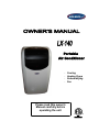
1
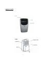
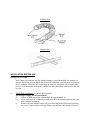
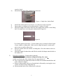
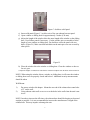
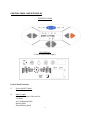
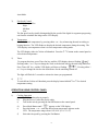
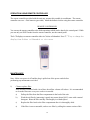
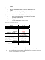
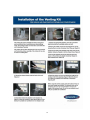
-
Please read this owner’s
Manual carefully before
operating the unit.
Cooling
Heating Pump
Dehumidifying
Fan
TABLE OF CONTENTS
INTRODUCTION…………………………………………………………………
2
IMPORTANT SAFEGUARDS………………………………………………..….2
PACKAGE CONTAINS…………………………………………………………..2
NAMES OF PARTS……………………………………………………………….3
INSTALLATION BEFORE USE……………………………..….………………4
CONTROL PANEL AND VFD DISPLAY………….…..……………………….5
CONTROL
FUNCTIONS……………………………………………….6
PANEL
OPERATION USING CONTROL PANEL………………………...….…..……7
OPERATION USING REMOTE CONTROLLER…………………………..…9
MAINTENANCE……………..……………………………….…..………………9
TECHNICAL
SPECIFICATIONS…………………………………….….…….10
DISCLAIMER……………………………………………………………………11
CONTACT INFORMATION…………………………………...………………11
WARRANTY……………………………………….………………………………….….…12
INSTALLATION OF THE VENTING KIT………….……………………….…….13
2
INTRODUCTION
Thank you for purchasing Soleus Air LX-140 portable air-conditioner. This unit is designed for
improving living and working comfort by providing cooling, heating, dehumidifying and fan
functions only with a minimum installation required. With its quite operation and attractive
design, you will enjoy the convenience and comfort that this unit provides for many years to come.
The unit also has power outage auto reset function. The unit automatically returns to the original
setting after a power outage.
IMPORTANT SAFEGUARDS
Before you use your portable air conditioner, please read this operation manual carefully.
1)
Never use or store gasoline or other flammable vapor or liquid near this unit.
2)
Maintain at least 10” (25 CM) clearance space from this unit. Avoid air inlet or
outlet grilles from being covered or closed off.
b)
The power supply must be properly grounded.
c)
Do not use an adapter plug or extension cord.
5)
Do not use the unit in the immediate surroundings of a bath, a shower or a
swimming pool.
6)
Do not let children play near this unit.
PACKAGE CONTAINS:
Mobile Air Conditioner
Exhaust Duct (2)
Unit Terminal End (2)
Window Kit Adapter (2)
Remote Controller
AAA Batteries (2)
Window Kit - 4 Sliding Panels
Exhaust Outlet Wall Covers (2)
Filter Outlet Panel Cover and Solid Panel Cover (2)
User Manual
3
NAMES OF PARTS
4
Exhaust Duct
Window Kits
INSTALLATION BEFORE USE
Binary Hose Design
Note: When you using the unit for cooling, heating or as a dehumidifier, the outdoor air
must be directed to the unit and the hot air must be exhausted out of the room to complete
the air exchange. When the unit is operating on fan mode, no outdoor air exchange takes
place. You do not need to hookup the window kits and exhaust hose when you use the unit
as a fan.
1)
Single Hose Installation: (1 exhaust duct required)
For fast spot cooling, use this installation.
a)
Pull out of both ends of the exhaust ducts for approximately 6”.
b)
Screw clockwise the exhaust ducts with one end to the terminal end and other end
to the window kit adapter.
c)
Remove only one exhaust outlet wall cover from the back of the unit by screwing
the covers counter-clockwise before lifting it up and leave the second wall cover
5
d)
securely closed.
Mount terminal ends of the exhaust hose to the unit.
Figure A. Single hose, Outlet Panel
e)
f)
g)
Insert Filter Outlet Panel Cover (Figure A.) to allow air to flow out panel.
Open window or sliding door for approximately 5 inches (130 mm)
Adjust the length of the window kit to the same length of the window or the sliding
door. For single hose select the panel with one hole (Figure B.)
Figure B
g)
h)
2)
Use all three panels if necessary. Cut the window piece as needed to fit the length
of your window or sliding door. Make sure the single hole panel is on the main
piece is not covered by other pieces.
Place the window kit to the window or sliding door. Close the window or door as
far as it goes.
Adjust the length of exhaust hose and affix the window kid adapter onto the hole on
the window kit.
Dual Hose installation: (2 exhaust ducts required)
Use this installation for maximum cooling and heating for a room.
a) Pull out of both ends of the exhaust ducts for approximately 6”.
b) Screw clockwise the exhaust ducts with one end to the terminal end and other end
to the window kit adapter.
c) Remove exhaust outlet wall covers from the back of the unit by screwing the covers
counter-clockwise before lifting them up.
d) Mount terminal ends of the exhaust hoses to the unit.
6
Figure C. dual hose solid panel
e) Insert solid panel (Figure C.) to allow air to flow out exhaust hose not panel.
f) Open window or sliding door for approximately 5 inches (130 mm)
g) Adjust the length of the window kit to the same length of the window or the sliding
door. Use all three panels if necessary. Cut the window piece as needed to fit the
length of your window or sliding door. For dual hose select the panel with two
holes. (Figure D.) Make sure that both holes on the main piece are not covered by
other pieces.
Figure D.
h) Place the window kit to the window or sliding door. Close the window or door as
far as it goes.
i) Adjust the lengths of exhaust hose and affix the window kid adapters onto the holes on the window kit.
NOTE: When using the window kit on a window or sliding door it will cause the window
or sliding door not to be properly closed and locked. Additional security measurements
should be taken
Wall Mount
1)
2)
Do not use window kit adapter. Mount the one end of the exhaust ducts onto holes
of 5” on the wall.
Using exhaust outlet wall covers to cover the holes in the wall when the unit is not
in use.
NOTE: In order to increase the efficiency, the exhaust ducts should be keeping as short and
straight as possible. It is not recommended to increase the manufacturer’s length of the
exhaust hose. This may impede or damage the unit.
7
CONTROL PANEL AND VFD DISPLAY
CONTROL PANEL
VFD DISPLAY
(Vacuum Fluorescent Display)
Control Panel Functions
1)
Power On/Off Control
Starts or Stops the Unit
2)
Mode Control
Select the functions of the unit for:
Fan Mode
Air Conditioning Mode
Heating Mode
Dehumidifying Mode
8
Auto Mode
3)
Fan Speed Control
Select the fan speed for:
High
Medium
Low
The fan speed can be visually distinguished by the speed of the digital air segments progressing
out from the windmill fan image on the VFD display.
4)
Temperature
Select the desired temperature by pressing either ∧or ∨ key when using the unit in cooling or
heating function. The VFD flashes to display the desired temperature during the setting. The
VFD displays set temperature when it is not at temperature setting mode.
The VFD display either in Celsius or Fahrenheit. Press the oF /0C button on the control panel to
select desired temperature.
5)
Timer
To program the timer, press Timer On key until the VFD display shows a flashing “
”.
Pressing either /\ or \/ keys to change the clock to the desired time for the unit being turned on.
Press Timer Off key and the VFD display will show a flashing “
”. Pressing either /\
or \/ keys to change the clock to the desired time for the unit being turned off.
The light will flash for 3 seconds to activate the timer you programmed.
6)
o
F / 0C
To switch from Celsius to Fahrenheit press the display button labeled oF or 0C for desired
temperature setting.
OPERATION USING CONTROL PANEL
1)
Cooling Operation
a)
Install the exhaust ducts properly.
b)
Plug the Power Cord to the power outlet.
c)
Turn on the unit by pressing the On/Off Button on the control panel.
d)
e)
Press Mode Button until “
” appears on the VFD display
Press the button ∧ or ∨ until the desired room temperature appears on the
VFD. The temperature ranges from 61oF-88 oF (16 oC-31 0C).
f)
Select the fan speed by pressing the Fan Button.
9
NOTE: During hot days, the unit will cool off the room most efficiently by setting the temperature at the
lowest and the fan speed at the highest. Reducing the length of the exhaust duct and insulating the
exhaust duct and keeping direct sunlight to a minimum will also improve the cooling efficiency.
2)
Dehumidifying Operation
a)
b)
c)
Install the exhaust ducts properly
Plug the Power Cord to the power outlet.
Turn on the unit by pressing the On/Off Button on the control panel.
d)
Press the Mode Button until the “
” appears on the VFD display.
NOTE: The unit operates at low fan speed during dehumidifying. The unit cools room slightly during
the dehumidification.
Keep the windows and the doors closed to aid the effectiveness of the unit in removing the moisture from
the room.
NOTE: The unit will not perform dehumidification when the room temperature is lower than 61 degree.
3)
Fan Operation
a)
b)
Plug the Power Cord to the power outlet.
Turn on the unit by pressing the On/Off Button on the control panel.
c)
d)
Press the Mode Button until “
” appears on the VFD display.
Select the fan speed by pressing the Fan Button.
NOTE: When the unit is running on fan mode, the exhaust duct is inoperative and is not required.
4)
Heating Operation
a)
b)
Plug the Power Cord to the power outlet.
Turn on the unit by pressing the On/Off Button on the control panel.
c)
d)
Press the Mode Button until “
“ appears on the VFD display.
Press the button ∧ or ∨ until the desired room temperature appears on the
VFD. The temperature ranges from 61 o F-88 o F (16 oC-31 oC).
e)
Select the fan speed by pressing the Fan button. It is recommended to use
the low fan
NOTE: When beginning heat mode, the unit will shut off for 3-5 minutes then resume to heating
operation.
5)
Auto Operation
a)
b)
Install the exhaust ducts properly
Plug the Power Cord to the power outlet.
10
c)
Turn on the unit by pressing the On/Off Button on the control panel.
d)
e)
” appears on the VFD display.
Press the Mode Button until the “
Select the fan speed by using FAN button.
During the AUTO model, the unit operates at heating mode when the room temperature is below 68 o F
degree. It operates at dehumidifying mode when the room temperature is between 68 o F to 80 o F degree.
It operates at cooling mode when the room temperature is above 80 degree. You may use the timer with
the AUTO mode.
6)
Sleep Mode (This Mode is available when using Remote control )
a)
b)
c)
The air conditioner is in operation
Press SLEEP Button, the “ ” appears on the VFD.
The fan motor of indoor unit runs in low speed
d)
When in cooling mode, within the first two hours, the temperature will be increased 1℉
per hour. Then temperature will be keeping at 2℉ higher than the originally set degree
for 6 hours. 6 hours later, temperature will return to the originally set degree.
When in heating mode, within the first 2 hours, temperature will be decreased 1℉ per
hour. Then temperature will be keeping at 2℉ Lower than the original degree for 6
hours.6 hours later, temperature will return to original degree you set.
When in dehumidify mode, the temperature will not be changed.
e)
g)
NOTE: When the room temperature is low and the indoor humidity is high, the condensate of the air
conditioner may not be discharged in time. Water will accumulate in the unit that leads to the unit stops
working automatically for a long time. (At the moment, the “
” appears on the VFD display.) In
order to let your unit recover working quickly, you can pull out the “Drain Port” which is located in the
lower left bottom of the back of the unit. The condensate will be discharged several minutes after water
be drained. Please use at least 1.5 liter pan to catch the dripping water.
It is not advised to use continuous drain method when the room temperature is higher than 90℉.
11
OPERATION USING REMOTE CONTROLLER
The remote controller provided with the unit may operate this portable air conditioner. The remote
controller uses two - AAA batteries (provided). Install the batteries before using the remote controller.
REMOTE CONTROLLER
You can use the remote controller to do all the operations which can be done by the control panel. While
you can only set SLEEP mode from the remote controller, not the control panel.
The LCD displays on remote controller either in Celsius or Fahrenheit. Press ℉/℃ key to change the
display from Celsius to Fahrenheit or vice verse.
MAINTENANCE
Note: Make sure power is off and the plug is pulled out of the power outlet before
performing any maintenance activities.
1)
Clean or replace filter
If the air filter is blocked with a lot of dust, the airflow volume will reduce. It is recommended
to clean the filter once every two weeks or as needed.
a)
Pull up the filter from the filter compartment in the back of the unit.
b)
Wash the air filter by immersing it gently into warm (about 104 F) water with a neutral
detergent. Rinse the filter and dry it thoroughly in a shaded place.
c)
Replace the filter back to the filter compartment after it is thoroughly dried.
a)
If the filter is torn or unusable, order a new filter by calling the contact section of this
12
manual.
2)
Case
3)
a.
Keep the unit from being exposed directly to the sun for possible color
fading.
b.
Clean the surface with a damp cloth. Dry it with a soft towel.
Storing the Unit for an Extended Period of Time or Transporting
a)
Empty water by unplugging the water drainage stop at the back
towards the bottom of the unit
b)
Unplug the unit.
c)
The unit should be stored in a cool dry place.
TECHNICAL SPECIFICATIONS
MODEL
COOLING CAPACITY
HEATING CAPACITY
DEHUMIDIFYING CAPACITY
POWER
COOLING
HEATING
AIR FLOW VOLUME
POWER SOURCE
SOUND PRESSURE LEVEL
NET WEIGHT
OPERATING
COOLING
TEMPERATURE
HEATING
DIMENSIONS
ASSEMBLED
PACKAGE
REFRIGERANT
LX-140
14,000 BTU/H
11,000 BTU/H
65 pts/Day
1610W
1610W
177 CFM
115 V~ 60 HZ
11/14 AMP
HEATING/COOLING
46 dB(A)
84 Lbs
60.8℉-108℉
23℉-89.6℉
1
19 /4x17 3/4x32 1/2 Inch
20x35x23 Inch
R22
NOTE:
1)
2)
3)
4)
The above cooling capacity is measured at ambient temperature of DB 86 F, WB 78 F.
Noise level is measured at the point where is 3.28 ft away from the front of the unit, in cooling mode.
Power consumption is measured when fan runs at the highest speed Specifications above are for reference only.
Please see the actual data printed on the nameplate.
If the environment temperature is higher than the max operating temperature or lower than the min operating
temperature, the air conditioner may not work properly.
13
DISCLAIMER
ALL INFORMATION AND THE TECHNICAL SPECIFICATIONS PRESENTED IN THIS USER’S MANUAL ARE
THE PRESENTATION OF THE MANUFACTURER. SOLEUS INTERNATIONAL HAS NOT CONDUCTED
INDEPENDENT TEST TO THE INFORMATION AND THE SPECIFICATIONS PRESENTED HEREWITHIN.
CONTACT INFORMATION
Contact For Optional and Spare Parts
Technical Support
Warranty Claim
Customer Service
Soleus International Inc.
9451 Telstar Ave.
El Monte, CA 91731 USA
(888) 8-SOLEUS
www.soleusair.com
14
WARRANTY
ONE YEAR LIMITED WARRANTY
Soleus International Inc. warrants the accompanying Soleus Air LX-140 Mobile Air Conditioner to be
free of defects in material and workmanship for the applications specified in its operation instruction for
a period of ONE (1) year from the date of original retail purchase in the United States or Canada.
If the air conditioner exhibits a defect in normal use, Soleus International Inc. will, at its option, either
repair or replace it, free of charge within a reasonable time after the air conditioner is returned during the
warranty period.
As a condition to any warranty service obligation, the consumer must present this Warranty Certificate
along with a copy of the original purchase invoice.
THIS WARRANTY DOES NOT COVER:
1) Damage, accidental or other wise, to the air conditioner while in the possession of a consumer not
caused by a defect in material or workmanship;
2) Damage caused by consumer misuse, tampering, or failure to follow the care and special
handling provisions in the instructions.
3) Damage to the finish of the case, or other appearance parts caused by wear.
4) Filter.
5) Damage caused by repairs or alterations of the air conditioner by anyone other than authorized
by Soleus International Inc..
6) Freight and Insurance cost for the warranty service.
ALL IMPLIED WARRANTIES, INCLUDING ANY IMPLIED WARRANTY OF MERCHANTABILITY ARE LIMITED
TO ONE-YEAR DURATION OF THIS EXPRESS LIMITED WARRANTY. SOLEUS INTERNATIONAL INC.
DISCLAIMS ANY LIABILITY FOR CONSEQUENTIAL OR INCIDENTAL DAMAGES AND IN NO EVENT SHALL
SOLEUS INTERNATIONAL INC.’S LIABILITY EXCEED THE RETAIL VALUE OF THE AIR CONDITIONER FOR
BREACH OF ANY WRITTEN OR IMPLIED WARRANTY WITH RESPECT TO THIS AIR CONDITIONER
15
16