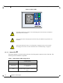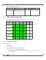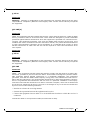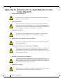
1
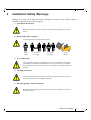
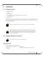
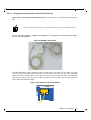
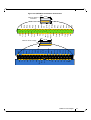
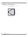
InfiniScale® IV 18-Port QSFP 40Gb/s InfiniBand
Switch User Manual
P/N:MIS5023Q-1BFR, MIS5023Q-1BRR
Rev 1.1
www.mellanox.com
Rev 1.1
NOTE:
THIS HARDWARE, SOFTWARE OR TEST SUITE PRODUCT (“PRODUCT(S)”) AND ITS RELATED DOCUMENTATION ARE
PROVIDED BY MELLANOX TECHNOLOGIES “AS-IS” WITH ALL FAULTS OF ANY KIND AND SOLELY FOR THE PURPOSE
OF AIDING THE CUSTOMER IN TESTING APPLICATIONS THAT USE THE PRODUCTS IN DESIGNATED SOLUTIONS. THE
CUSTOMER'S MANUFACTURING TEST ENVIRONMENT HAS NOT MET THE STANDARDS SET BY MELLANOX
TECHNOLOGIES TO FULLY QUALIFY THE PRODUCTO(S) AND/OR THE SYSTEM USING IT. THEREFORE, MELLANOX
TECHNOLOGIES CANNOT AND DOES NOT GUARANTEE OR WARRANT THAT THE PRODUCTS WILL OPERATE WITH THE
HIGHEST QUALITY. ANY EXPRESS OR IMPLIED WARRANTIES, INCLUDING, BUT NOT LIMITED TO, THE IMPLIED
WARRANTIES OF MERCHANTABILITY, FITNESS FOR A PARTICULAR PURPOSE AND NONINFRINGEMENT ARE
DISCLAIMED. IN NO EVENT SHALL MELLANOX BE LIABLE TO CUSTOMER OR ANY THIRD PARTIES FOR ANY DIRECT,
INDIRECT, SPECIAL, EXEMPLARY, OR CONSEQUENTIAL DAMAGES OF ANY KIND (INCLUDING, BUT NOT LIMITED TO,
PAYMENT FOR PROCUREMENT OF SUBSTITUTE GOODS OR SERVICES; LOSS OF USE, DATA, OR PROFITS; OR BUSINESS
INTERRUPTION) HOWEVER CAUSED AND ON ANY THEORY OF LIABILITY, WHETHER IN CONTRACT, STRICT LIABILITY,
OR TORT (INCLUDING NEGLIGENCE OR OTHERWISE) ARISING IN ANY WAY FROM THE USE OF THE PRODUCT(S) AND
RELATED DOCUMENTATION EVEN IF ADVISED OF THE POSSIBILITY OF SUCH DAMAGE.
Mellanox Technologies
350 Oakmead Parkway Suite 100
Sunnyvale, CA 94085
U.S.A.
www.mellanox.com
Tel: (408) 970-3400
Fax: (408) 970-3403
© Copyright 2011. Mellanox Technologies. All rights reserved.
Mellanox, BridgeX, ConnectX, Virtual Protocol Interconnect, InfiniBlast, InfiniBridge, InfiniHost, InfiniRISC, InfiniScale, and InfiniPCI
are registered trademarks of Mellanox Technologies, Ltd. CORE-Direct, FabricIT, and PhyX are trademarks of Mellanox Technologies, Ltd.
All other trademarks are property of their respective owners.
All other marks and names mentioned herein may be trademarks of their respective companies.
QDR InfiniBand Switch Platform User Manual
2
Mellanox Technologies
Document Number: 3329
QDR InfiniBand Switch Platform User Manual
Rev 1.1
Contents
Contents
3
List of Figures
5
List of Tables
6
Revision History
7
About this Manual
8
Intended Audience
Related Documentation
Conventions
Mellanox Part Numbering Legend
Chapter 1
8
8
8
9
Overview
10
1.1 Serial Number and Product Version Information
10
Chapter 2
Installation Safety Warnings
11
Chapter 3
Externally Managed Switches
14
Chapter 4
Hardware Basic Operation and Installation
15
4.1 Switch Platform Hardware Overview
4.1.1 LED Assignments
4.2 Air Flow
4.3 QSFP Cable Power Budget Classification
4.4 Interfaces
4.4.1 Port Connector Interfaces
4.5 Management and Firmware Updating Interfaces
4.5.1 RJ-45 Connector (I2C)
15
15
18
18
19
19
19
19
Installation
21
5.1 Package Contents
5.2 Installing the Switch in the Rack
5.2.1 Grounding the Switch
5.2.2 Power Connections and Initial Power On
5.2.3 InfiniBand Cable Installation
5.3 Disassembly of the Switch from the Rack
5.3.1 Disassembly Procedure — Single Switch Centered Installation
5.4 Disposal
5.5 Updating Firmware
5.5.1 Current Firmware Revision
5.5.2 How to Get Mellanox Firmware Tools (MFT)
5.5.3 Open SM
21
21
23
24
24
24
24
25
25
25
28
28
Troubleshooting
29
Chapter 5
Chapter 6
Appendix A Specification
A.1
A.2
A.3
EMC Certification Statements
VCCI Statements (Japan)
MIC Certification (Korea)
31
32
34
34
Appendix B QSFP Interface
36
Appendix C RJ45 I2C Interface
38
Appendix D Replacement Parts Ordering Numbers
39
Appendix E Avertissements de sécurité d’installation (French)
40
Appendix F Installation - Sicherheitshinweise (German)
42
Mellanox Technologies
3
Rev 1.1
Appendix G Advertencias de seguridad para la instalación (Spanish)
44
Appendix H Special Regulations Regarding Finland, Sweden, Denmark, and Norway
47
4
Mellanox Technologies
QDR InfiniBand Switch Platform User Manual
Rev 1.1
List of Figures
Figure 1:
Generic Product label
10
Figure 2:
Switch System Front Panel
15
Figure 3:
Status LEDs
16
Figure 4:
Port Numbering
19
Figure 5:
RJ45 I2C Connector
19
Figure 6:
Rail and Rail Slide
22
Figure 7:
Screw on the Switch Slide
23
Figure 8:
MTUSB-1 with Cables
27
Figure 9:
I2C Cable Connected to IS5023
27
Figure 10: QSFP Male and Female Connections
37
Mellanox Technologies
5
Rev 1.1
List of Tables
Table 1:
Revision History Table
7
Table 2:
Reference Documents
8
Table 3:
Switch Status LED Configurations
16
Table 4:
Fan LED Configurations
17
Table 5:
Bad Port LED Configurations
17
Table 6:
Connector Physical and Logical Link Indications
18
Table 7:
IS5023 Specification Data
31
Table 8:
Switch Certification Status
32
Table 9:
InfiniBand QSFP Connector Pinout
36
Table 10:
Replacement Parts Ordering Numbers
39
6
Mellanox Technologies
QDR InfiniBand Switch Platform User Manual
Rev 1.1
Revision History
Table 1 - Revision History Table
Date
Revision
Description
May, 2011
1.1
Fixed power numbers
Sept, 2010
1.0
Initial release
Mellanox Technologies
7
Rev 1.1
About this Manual
This manual describes the installation and basic use of the Mellanox IS5023 switch, which is
based on the InfiniScale® IV InfiniBand switch device.
Intended Audience
This manual is intended for users and system administrators responsible for installing and setting
up the switch platforms listed above.
The manual assumes familiarity with the InfiniBand® Architecture Specification.
Related Documentation
Additional Documentation available from Mellanox:
Table 2 - Reference Documents
Switch Firmware and See
Firmware Update
http://www.mellanox.com > Support > Download Firmware Tools
Tools
Note that the Switch System described in this manual is based on Mellanox
Technologies’ InfiniScale® IV switch device.
Mellanox OFED
Stack for Linux
User’s Manual
See
http://www.mellanox.com > Support > InfiniBand Software and Drivers
Click “Mellanox OpenFabrics Enterprise Distribution for Linux
(MLNX_OFED)”
Select the Linux User’s Manual
The embedded OS and tools on the CPU in the management module is a
subset of the Mellanox OFED stack.
Mellanox Firmware
Tools (MFT)
User’s Manual
Document # 2329
The MFT (Mellanox Firmware Tools) package is a set of firmware tools.
The manual supplied with this package provides an overview of the firmware its installation and replacement. The MFT can be downloaded with its
documentation at:
http://www.mellanox.com > Support > Download Firmware Tools
Conventions
Throughout this manual, the name IS5023 and the term switch are used to describe the 18-port
QSFP 40Gb/s InfiniBand Switch unless explicitly indicated otherwise.
8
Mellanox Technologies
QDR InfiniBand Switch Platform User Manual
Rev 1.1
This symbol indicates information that is helpful to the user.
BEWARE! This symbol indicates a situation that can potentially cause personal injury
or damage to hardware or software.
Mellanox Part Numbering Legend
Place
Field
M
Decoder
Mellanox Technologies
IS
System Type
InfiniScale Switch
50
Model
Family
FF
Form factor
23 = 18 Ports
-
Separator
#
Power supplies
1 = 1 power supply
M
Depth of the Unit
B = short depth
Y
Air Flow direction
R= Connector side to rear side airflow
F= Rear side to connector side airflow
R
RoHS
R=RoHS6
Mellanox Technologies
9
Rev 1.1
1
Overview
Overview
This User Manual provides an overview of the InfiniBand switch product, an 18-port switch capable of up to1.44Tb/s of non-blocking switching capacity. Based on the fourth generation InfiniScale InfiniBand switch device. The platform delivers industry leading bandwidth, latency, and
scalability in a 1U form factor. The platform can be tiered to build larger multi stage networks in a
variety of topologies such as Fat-Tree, Mesh, 3D Torus etc. All port configurations are covered in
this manual which include switches for QSFP InfiniBand ports.
Mellanox IS5023 switch systems are an ideal choice for top-of-rack connectivity from small to
extremely large sized clusters. Networks built with IS5023 systems can carry converged traffic
with the combination of assured bandwidth and granular quality of service. IS5023 systems provide up to 40Gb/s full bidirectional bandwidth per port.
The switch platform comes pre-installed with all necessary firmware and is configured for standard operation within an InfiniBand fabric. This switch requires an InfiniBand compliant Subnet
Manager running from one of the hosts or another managed switch. All that is required for normal
operation is to follow the usual precautions for installation and to connect the switch to the HCAs
or other switches within the fabric. Once connected, the Subnet Management software automatically configures and begins utilizing the switch.
It is recommended that the Mellanox OpenFabrics software package be installed on all nodes connected to the IS5023. The software package provides a subnet manager and network management
tools as well as connectivity software for servers and storage, and is available on the Mellanox
web site. See Chapter 3 for more information.
Basic installation and hardware maintenance is covered in “Hardware Basic Operation and Installation” on page 15.
1.1
Serial Number and Product Version Information
The Serial number and GUID for the switch are found on the front panel below the I2C interface
connection. The serial number and product version information are found on the label seen in the
figure below.
Figure 1: Generic Product label
P/N: MIS5023Q-1BRR
Rev: X1
S/N: MT0924X00266
GUID: 0002C9020040DDB0
Made in IL
Also on this label is the GUID identifier for the switch.
10
Mellanox Technologies
QDR InfiniBand Switch Platform User Manual
2
Rev 1.1
Installation Safety Warnings
Warnings in French can be found on page 40. Warnings in German can be found on page 42.
Warnings in Spanish can be found on page 44.
1. Installation Instructions
Read all installation instructions before connecting the equipment to the power
source.
2. Bodily Injury Due to Weight
Use enough people to safely lift this product.
<40 lbs
<18 kgs
40 - 70 lbs
18 - 32 kgs
70 - 121 lbs
32 - 55 kgs
>121 lbs
>55 kgs
3. Over-temperature
This equipment should not be operated in an area with an ambient temperature
exceeding the maximum recommended: 45°C (113°F). Moreover, to guarantee
proper air flow, allow at least 8cm (3 inches) of clearance around the ventilation
openings.
4. Stacking the Chassis
The chassis should not be stacked on any other equipment. If the chassis falls, it
can cause bodily injury and equipment damage.
5. During Lightning - Electrical Hazard
During periods of lightning activity, do not work on the equipment or connect or
disconnect cables.
Mellanox Technologies
11
Rev 1.1
Installation Safety Warnings
6. Copper InfiniBand Cable Connecting/Disconnecting
Copper InfiniBand cables are heavy and not flexible, as such they should be
carefully attached to or detached from the connectors. Refer to the cable manufacturer for special warnings/instructions.
7. Rack Mounting and Servicing
When this product is mounted or serviced in a rack, special precautions must be
taken to ensure that the system remains stable. In general you should fill the
rack with equipment starting from the bottom to the top.
8. Equipment Installation
This equipment should be installed, replaced, and/or serviced only by trained
and qualified personnel.
9. Equipment Disposal
Disposal of this equipment should be in accordance to all national laws and regulations.
10. Local and National Electrical Codes
This equipment should be installed in compliance with local and national electrical codes.
11. UL Listed and CSA Certified Power Supply Cord
For North American power connection, select a power supply cord that is UL Listed
and CSA Certified, 3 - conductor, [16 AWG], terminated with a molded plug rated at
125 V, [13 A], with a minimum length of 1.5m [six feet] but no longer than 4.5m.
For European connection, select a power supply cord that is internationally
harmonized and marked “<HAR>”, 3 - conductor, minimum 1.0 mm 2 wire,
rated at 300 V, with a PVC insulated jacket. The cord must have a molded plug
rated at 250 V, 10 A.
12
Mellanox Technologies
QDR InfiniBand Switch Platform User Manual
Rev 1.1
12. Add GND connection information
Before connecting this device to the power line, the protective earth terminal screws of
this device must be connected to the protective earth in the building installation.
(GND Connection Information):
The building installation shall provide a means for connection to protective earth; and
the equipment shall to be connected to that means permanently by a service person.
A SERVICE PERSON shall check whether or not the socket - outlet from which the
equipment is to be powered provides a connection to the building protective earth. If
not, the SERVICE PERSON shall arrange for the installation of a PROTECTIVE
EARTHING CONDUCTOR from the separate protective earthing terminal to the protective earth wire in the building. The equipment shall be installed in area where equipotential bonding exists (such as a telecommunication centre or a dedicated computer
room)
13. Installation codes
This device must be installed according to the latest version of the country national
electrical codes. For North America, equipment must be installed in accordance to the
applicable requirements in the US National Electrical Code and the Canadian Electrical Code.
14. WEEE Directive
According to the WEEE Directive 2002/96/EC, all waste electrical and electronic equipment (EEE) should be collected separately and not disposed of with
regular household waste.
Dispose of this product and all of its parts in a responsible and environmentally
friendly way.
Mellanox Technologies
13
Rev 1.1
3
Externally Managed Switches
Externally Managed Switches
Externally managed (unmanaged) switches are plug and play out of the box. All switches come
with the latest firmware (FW) burned on the Flash. Updating the FW on externally managed
switches can be performed in-band only. When new FW is available, an email notification is sent
to registered users with the link to the Mellanox FW download site. The download site has the
Mellanox FW tool package and full instructions for updating FW.
Externally managed switches must be managed by management software installed on a node or on
another managed switch that can be anywhere in the fabric. This can be OpenSM, Mellanox
FabricIT™ EFM, Mellanox UFM™, or a third party Subnet Manager.
14
Mellanox Technologies
QDR InfiniBand Switch Platform User Manual
Rev 1.1
4
Hardware Basic Operation and Installation
4.1
Switch Platform Hardware Overview
Figure 2 shows the front view of the switch. The figure shows port configurations for the switch
systems, I2C connector, and various status LEDs. Externally Managed switches come with an I2C
RJ45 connector.
Figure 2: Switch System Front Panel
I2C
1
2
3
4
5
6
7
8
9
10
11
12
13
14
15
16
17
IS5023
18
P/N: MIS5023Q-1BRR
UID
Rev: X1
S/N: MT0924X00266
GUID: 0002C9020040DDB0
Made in IL
Mellanox ®
All InfiniBand connectivity is via the connector side panel. All connectors can support active
cables.
4.1.1 LED Assignments
4.1.1.1
System Status Indicators
The System Status Indicators are located on the left side of the front (connector side) panel. The
system status indicators should display as follows:
When the switch is plugged in, within three seconds:
• the Status LED
should light up green.
• The Fan LED
should light up green.
• The Bad Port LED
should be off.
• The Unit ID LED UID should be off.
Mellanox Technologies
15
Rev 1.1
Hardware Basic Operation and Installation
Figure 3: Status LEDs
UID
Mellanox
®
If the Status LED shows red after 30 seconds unplug the switch and call your Mellanox
representative for assistance.
If the Fan LED shows red unplug the switch and call your Mellanox representative for
assistance.
If the switch shuts down due to over temperature, unplug the switch, wait 5 minutes
and replug in the switch. For more information See “Troubleshooting” on page 29.
4.1.1.2
Status LED
The Status indicator is located on the left side of the front panel (connector side) of the unit. The
following status conditions are possible:
Table 3 - Switch Status LED Configurations
LED Description
16
Off
No power to the switch
Solid Green
Switch is running
All OK
Red
There is a problem with power output from
the power supply, or there is a thermal shut
down.
Mellanox Technologies
QDR InfiniBand Switch Platform User Manual
4.1.1.3
Rev 1.1
Fan Indicators
The Fan indicator is located on the left side of the front panel (connector side) of the unit. The following fan status conditions are possible:
Table 4 - Fan LED Configurations
LED Configuration
FAN LED
Off
There is no power to the fans.
Green
OK – The fans are running.
Red
Error – fans are not operating properly. Replace the switch.
Fans must be operating while the power supply is plugged in.
If the switch shuts down due to over temperature, unplug the switch, wait 5 minutes
and replug in the switch. For more information See “Troubleshooting” on page 29.
4.1.1.4
Bad Port LED
The Bad Port indicator is located on the left side of the front panel (connector side) of the unit. The
following Bad Port conditions are possible:
Table 5 - Bad Port LED Configurations
LED Configuration
Description
Off
OK – All ports are up and running.
Flashing Orange
Error –One or possibly more ports has just received a symbol error.
This LED shows symbol errors. Possible causes for this are:
• bad cable
• bad connection
• bad connector
This LED lights up when one or more ports is receiving a symbol error. The LED immediately
goes off until the next symbol error is received.
Mellanox Technologies
17
Rev 1.1
4.1.1.5
Hardware Basic Operation and Installation
UID LED Switch Identifier
The UID LED is a debug feature that will become available to customers in the near future. For
details please contact Mellanox Technologies support.
4.1.1.6
Port Connector LED
Above the ports is a single LED
LED indication.
. The following table shows the port status according to the
Table 6 - Connector Physical and Logical Link Indications
LED Description
Off
No link
Orange
Physical Link up
Solid Green
Logical Link up
Flashing Green
Data activity
flashing speed ≈ data transfer speed
Flashing Orange
A problem with the Physical Link
This LED when flashing orange shows port physical errors. Possible causes for this are:
• bad cable
• bad connection
• bad connector
• bad cage
4.2
Air Flow
These switches can come with two air flow patterns. The two patterns are
• Rear side inlet to connector side outlet
• Connector side inlet to rear side outlet
The air flow is specified in the product model number. See “Mellanox Part Numbering Legend” on
page 9.
4.3
QSFP Cable Power Budget Classification
All IS5023 QSFP switches are designed for active cables with a max power per module of 2.0W.
This is power level 2 according to the QSFP Public Specification.
18
Mellanox Technologies
QDR InfiniBand Switch Platform User Manual
4.4
Rev 1.1
Interfaces
4.4.1 Port Connector Interfaces
The Connector side of the switch has 18 QSFP ports.These are placed in a single row.
Figure 4: Port Numbering
1
4.5
2
3
4
5
6
7
8
9 10
11 12
13 14 15 16 17 18
Management and Firmware Updating Interfaces
The externally managed switch platform does not require any programming or configuration to
operate as a basic InfiniBand switch and includes all of the necessary functionality to operate with
external standard InfiniBand Subnet Management software such as OFED, FabricIT, UFM etc.
There is one interface to connect to the switch. It is an I2C RJ45 interface labelled “I2C”. Use this
connector to update firmware (as a last resort) and for advanced debug.
Update FW inband only.
4.5.1 RJ-45 Connector (I2C)
There is an “I2C”interface on the front panel.
Figure 5: RJ45 I2C Connector
I2C
IS5023
18
P/N: MIS5023Q-1BRR
Rev: X1
S/N: MT0924X00266
GUID: 0002C9020040DDB0
Made in IL
All firmware updates should be done in-band using Mellanox Firmware Management Tools.
The I2C connector is available only on externally managed switches and is used to update firmware should in-band firmware update not work. You will need to order an MTUSB-1 USB to I2C
adapter to make use of the I2C interface. The I2C connection provides access to Flash and
EEPROMs. This is for Advanced users and FAEs only.
Mellanox Technologies
19
Rev 1.1
Hardware Basic Operation and Installation
The externally managed switches are Plug and Play and all firmware updates should be
done in-band. The I2C connection should only be used if the FW image was corrupted
to the point that the regular FW tools cannot successfully reburn the correct image.
Warning: Any red status LED is cause for concern and must be dealt with immediately.
It can take up to 30 seconds to boot up, during which time the status LED may
indicate red.
20
Mellanox Technologies
QDR InfiniBand Switch Platform User Manual
5
Installation
5.1
Package Contents
Rev 1.1
The package includes:
• 1 switch
• 1 installation kit
• 1 box containing 1 power cord Type B 6ft US 125V 10A chord
• 1 installation guide
• 1 parts list
Before you install your new switch, unpack the system and check to make sure that all the parts
have been sent, check this against the parts list. Check the parts for visible damage that may have
occurred during shipping.
If anything is damaged or missing, contact your customer representative immediately.
The rack mounting holes conform to the IEA-310 standard for 19-inch racks. Guarantee
proper ventilation, by leaving 8cm (3”) of space to the front and rear of the switch. This
will ensure proper air flow through the chassis. This is crucial for maintaining good airflow at ambient temperature. In particular, route cables such that they do not impede the
air into or out of the chassis.
5.2
Installing the Switch in the Rack
This installation kit can only be used to install this switch.
Tools and Parts
Tools required and customer supplied parts
• Phillips Screwdrivers #1 and #2
• ESD Strap
• ESD mat
• Grounding screw
• Grounding wire sufficient to reach a valid ground
Mellanox Technologies
21
Rev 1.1
Installation
Parts Included in the Installation Kit:
• 2 rails
• 2 rail slides
• 6 recessed flat head screws
• 8 caged nuts with pan head screws
Figure 6: Rail and Rail Slide
Rail
Rail slide
Flat head screws
Caged nuts and bolts
The following procedure can be done by one person.
15.
1.
2.
22
Place the ESD mat on the floor where you will be working and put on the ESD strap. Make
sure the ESD strap is touching your skin and that the other end is connected to a verified
ground.
Screw the rail slides to the switch. Make sure that the ears on the slide are on the connector
side of the switch. Use three flat head screws for each rail slide.
Mellanox Technologies
QDR InfiniBand Switch Platform User Manual
Rev 1.1
Figure 7: Screw on the Switch Slide
3.
4.
5.
6.
7.
8.
9.
Put 8 caged nuts into the rack at the level you want to install the switch.
Screw the rails to the rack.
Slide the switch onto the rail slides, and screw the switch to the rack.
Tighten all of the screws.
Ground the switch.
Plug in the power cord.
You can start connecting all of the cables to the switch.
5.2.1 Grounding the Switch
Check to determine if your local or national electrical codes require an external ground to all IT
components. If so, connect a ground wire to one of the casing screws and connect the other end to
a valid ground. If you choose to not use the ground screw, make sure that the rack is properly
grounded and that there is a valid ground connection between the chassis of the switch and the
rack. Test the ground using an Ohm meter.
Some national and/or local codes may require IT components to be bonded and externally grounded (not including the power cord ground). You must follow all national and
local codes when installing this equipment.
Mellanox Technologies
23
Rev 1.1
Installation
5.2.2 Power Connections and Initial Power On
The power cord is included in the installation kit.
Caution: The switch platform will automatically power on when AC power is applied.
There is no power switch.
Caution: After inserting a power cable and confirming the green system status LED
light is on; make sure that the Fan Status indicator shows green.
If the fan status indicator is not green then unplug the power connection and call your
supplier.
5.2.3 InfiniBand Cable Installation
All cables can be inserted or removed with the unit powered on. To insert a cable, press the connector into the port receptacle until the connector is firmly seated. The orange LED indicator corresponding to each QSFP port will light when the physical connection is established (that is, when
the unit is powered on and a cable is plugged into the port with the other end of the connector
plugged into a functioning port). After plugging in a cable, lock the connector using the latching
mechanism particular to the cable vendor. When a logical connection is made the green light will
come on. When data is being transferred the light will blink green.
To remove, disengage the locks and slowly pull the connector away from the port receptacle. The
LED indicator will turn off when the cable is unseated.
Care should be taken not to impede the air exhaust flow through the ventilation holes next to the
InfiniBand ports. Cable lengths should be used which allow for routing horizontally around to the
side of the chassis before bending upward or downward in the rack.
5.3
Disassembly of the Switch from the Rack
5.3.1 Disassembly Procedure — Single Switch Centered Installation
To disassemble the switch from the rack:
1.
2.
3.
4.
5.
24
Unplug and remove all connectors.
Unplug the power cord.
Remove the ground wire.
Remove the four M6 screws holding the switch to the rack. Support the switch while removing the screws, or the switch may fall out of the rack.
Slide the switch out of the rack.
Mellanox Technologies
QDR InfiniBand Switch Platform User Manual
Rev 1.1
This switch needs to be supported when it is being disassembled.
6.
7.
5.4
Remove the rails.
Remove the caged nuts.
Disposal
According to the WEEE Directive 2002/96/EC, all waste electrical and electronic equipment (EEE) should be collected separately and not disposed of with
regular household waste.
Dispose of this product and all of its parts in a responsible and environmentally
friendly way.
For proper disassembly instructions see the Mellanox website.
5.5
Updating Firmware
When you buy the switch, it comes with the latest firmware burned on the board. All firmware
updates should be done in-band. Go to the Mellanox Website and confirm that the firmware is the
latest. If not reburn the latest firmware from the download site. New firmware versions will be
posted on the Mellanox firmware download page:
http://www.mellanox.com => Support > Download Center.
You will need the Mellanox Firmware Tools package to update firmware for this switch. It can also
be downloaded from:
http://www.mellanox.com. => Support > InfiniBand Software and Drivers.
You will also need to download and unzip the firmware binary image. This is provided in the Mellanox Web site at: http://www.mellanox.com => Support > Download Center and go to the InfiniScale IV Switch systems. Click in the Table for the firmware image that you need.
5.5.1 Current Firmware Revision
The user can query for the currently loaded firmware revision by using the command:
ibstat
(part of mft package). Other tools like flint can also be useful.
Mellanox Technologies
25
Rev 1.1
Installation
5.5.1.1
Instructions for Reprogramming Over the InfiniBand Network
To update an InfiniScale IV switch device having a specific GUID (for example,
0x00000006660abcd0) or LID, the following are the recommended steps to update the device
firmware.
1.
Make sure all subnet ports are in the active state. One way to check this is to run opensm, the
Subnet Manager.
[root@mymach]> /etc/init.d/opensmd start
opensm start
[ OK ]
2.
3.
Make sure the local ports are active by running ‘ibv_devinfo’.
Obtain the device LID.
1. Use the “mst ib add” command:
The “mst ib add” runs the ibdiagnet/ibdiscover tool to discover the InfiniBand fabric and then lists the discovered
IB nodes as an mst device under /dev/mst/ directory. These devices can be used for access by other MFT tools.
[root@mymach]> mst ib add
-I- Discovering the fabric - Running: ibdiagnet -skip all
-I- Added 10 in-band devices
2. List the discovered mst inband devices run “mst status”.
[root@mymach]> mst status
MST modules:
-----------MST PCI module loaded
MST PCI configuration module loaded
...
Inband devices:
------------------/dev/mst/CA_MT25418_sw005_HCA-1_lid-0x0001
/dev/mst/SW_MT47396_lid-0x0011
/dev/mst/SW_MT48438_lid-0x0003
Identify the switch you want to update according to its description or its LID.
in the examples below we will use SW_MT48438_lid-0x0003 as our target switch.
Query the switch to determine the current FW version:
[root@mymach]> flint -d /dev/mst/SW_MT48438_lid-0x0003 q
Image type:
FS2
FW Version:
7.3.0
Device ID:
48438
Chip Revision: A0
Description:
Node
Sys image
GUIDs:
0002c902004177d8 0002c902004177db
Board ID:
n/a (MT_0D00110012)
VSD:
n/a
PSID:
MT_0D00110012
Burn the InfiniScale IV switch:
flint -d /dev/mst/SW_MT48438_lid-0x0003 -i ./fw-IS4-rel-7_4_0-Q_A1.bin -qq b
26
Mellanox Technologies
QDR InfiniBand Switch Platform User Manual
5.5.1.2
Rev 1.1
Reprogramming the Switch Through The I2C Port
This interface is for Debug and Troubleshooting only. This interface is for FAEs and advanced users
only.
The I2C connector should only be used when the firmware cannot be updated in-band.
Use the MTUSB-1 adapter (available from Mellanox) to reprogram the switch firmware using a
server or PC running MFT.
Figure 8: MTUSB-1 with Cables
The MTUSB adapter comes with three cables, but has only two connections for cables. One cable
is an I2C cable with DB9 female connectors on both ends. One cable is a I2C cable with DB9
female connector to RJ45 male. Use the cable that matches your switch. The other is a USB cable
with one type A host connection to be connected to the server or PC and a type B connection to be
connected to the MTUSB adapter.
Figure 9: I2C Cable Connected to IS5023
IS5023
Mellanox Technologies
27
Rev 1.1
Installation
With the switch connected to a computer through the MTUSB, it is now possible to reprogram the
SPI Flash memory.
5.5.1.3
Instructions for Reprogramming Through the I2C Port
1.
Make sure that:
•the MTUSB I2C cable is connected to the switch and USB cable is connected to a computer
•MFT is running on the computer
•"mtusb-1" mst device appears in "mst status"
2.
Set the switch I2C switch to allow access by running:
> mlxi2c -d /dev/mst/mtusb-1 -s IS5023 p /IS4
3.
Run the burn command:
flint -d /dev/mst/mtusb-1 -i ./fw-IS4-rel-7_4_0-Q_A1.bin -qq b
4.
Power cycle the switch, by unplugging and re-plugging the power cord, to load the new firmware.
5.5.2 How to Get Mellanox Firmware Tools (MFT)
Mellanox Firmware Tools (MFT) and documentation are available for download via
http://www.mellanox.com > Support > Download Firmware Tools.
The MFT kit includes:
• mlxburn
• flint
• spark
• IBspark
• debug utilities
See “Related Documentation” on page 8.
5.5.3 Open SM
To manage the Mellanox switch system using OFED, download Mellanox Open Fabrics from
http://www.mellanox.com > Support > InfiniBand Software and Drivers.
Be sure to read and follow all of the instructions regarding the installation and use of these tools.
28
Mellanox Technologies
QDR InfiniBand Switch Platform User Manual
6
Rev 1.1
Troubleshooting
As soon as a switch is plugged in, continuously monitor the status light. Make sure that it turns
green within 30 seconds of booting up.
Status LED and Fan LED
If the Fan LED is red make sure that the ambient temperature is within the range specified in the
Specification section of the Appendix.
If any of the LEDs are red after 30 seconds, unplug the switch and call your Mellanox representative.
Power supply unit:
1.
Check that the power cable has a voltage within the range of 100 - 240 volts AC.
If the status LED is red.
2.
Remove and reinstall the power cable.
The green power LED for the fans does not come on:
.
Caution: Do not run the switch if the System Status LED for the Fans is red or
off!
The connector LED for the InfiniBand connector does not come on:
1.
2.
3.
4.
Check that both ends of the cable are connected.
Check that the locks on the ends are secured.
Make sure that the latest FW version is installed on both the HCA cards and the switch.
If media adapters are used, check that the all connections are good, tight, and secure.
The connector LED is flashing orange:
1.
Check that the Subnet Manager has been started.
2.
Check the cable is connected properly at borh ends.
3.
Check the the cable is good.
4.
Check that the connections are good(no cable weight on the connector, no twists in the cable
at the connector...).
5.
Check the port connectors at both ends.
The switch is off:
1.
2.
3.
Unplug the switch.
Wait 5 minutes.
Plug in the switch.
Mellanox Technologies
29
Rev 1.1
Troubleshooting
4.
5.
6.
7.
8.
If the switch does not come on, check the power supply.
If the switch comes on, Use the management software to determine the cause of the shutdown.
Check the temperature of the switch.
Check the ambient air temperature to make sure it is not too high.
Check the Fan status.
The switch is not working and unresponsive:
1.
2.
3.
4.
5.
30
Unplug the switch.
Wait 5 minutes.
Plug in the switch.
If the switch does not come on, check the power supplies.
If the switch comes on, use the management software to determine the cause of the shutdown.
Mellanox Technologies
QDR InfiniBand Switch Platform User Manual
Rev 1.1
Appendix A: Specification
Table 7 - IS5023 Specification Data
Physical
Size:
Weight:
Mounting:
SerDes Speeds
Connectors and
Cabling:
Port Types:
1.73” (1U) H x 17.3” W x 16.14” D
44mm X 440mm X 410mm
13 lb. / 5.9kg
19” Rack mount
Power and Environmental
Input Voltage:
Power Consumption Typ:
18 port QDR
Passive Cables
Active Cables
QSFP Cable
Power Consumption Max:
18 port QDR
Passive Cables
Active Cables
73.85W
118.30W
QSFP
Temperature:
Humidity:
Protocol Support
QoS:
65.91 W
110.36 W
10, 20, 40 Gb/s per port
QSFP Max
Power per port
for active cables:
InfiniBand:
100-240 VAC 50-60Hz
Auto-Negotiation of (40Gb/s, 20Gb/s,
10Gb/s)
8 InfiniBand Virtual Lanes for all
ports
Management:
Baseboard, Performance, and Device
management Agents for full
InfiniBand In-Band Management
0 to 45 Celsius
10% - 90% non-condensing
Regulatory Compliance
Safety:
US/Canada: cTUVus
EU: IEC60950
International: CB
EMC (Emissions):
USA: FCC, Class A
Canada: ICES, Class A
EU: EN55022, Class A
EU: EN55024, Class A
EU: EN61000-3-2, Class A
EU: EN61000-3-3, Class A
Japan: VCCI, Class A
Environmental:
EU: IEC 60068-2-64: Random Vibration
EU: IEC 60068-2-29:
Shocks, Type I / II
EU: IEC 60068-2-32: Fall
Test
RoHS R-6
Acoustic:
Sound power
level:
Scalability and Performance
2.0W
ISO 7779
ETS 300 753
70.5 dB(A) or 7.1 Bel
Reliability, Availability and Serviceability
Features
Mellanox Technologies
31
Rev 1.1
Table 7 - IS5023 Specification Data
Physical
Switching Performance:
Addressing:
Switching Capacity
A.1
Power and Environmental
Simultaneous wire-speed any port to
any port
48K Unicast Addresses Max. per Subnet
16K Multicast Addresses per Subnet
720Gb/s
EMC Certification Statements
Table 8 lists the approved certification status per switch in different regions of the world.
Table 8 - Switch Certification Status
A.1.1
Switch P/N
FCC
Class
(USA)
EN
Class
(Europe)
ICES
Class
(Canada)
VCCI
(Japan)
IS5023Q-1BFR
YES
YES
YES
YES
IS5022Q-1BFR
YES
YES
YES
YES
IS5022Q-1BRR
YES
YES
YES
YES
IS5022Q-1BFC
YES
YES
YES
YES
IS5022Q-1BRC
YES
YES
YES
YES
cTUVus
CB
FCC Statements (USA)
Class A Statements:
§ 15.19(a)(4)
This device complies with Part 15 of the FCC Rules.
Operation is subject to the following two conditions:
1.
2.
32
This device may not cause harmful interference, and
This device must accept any interference received, including interference that may cause
undesired operation.
Mellanox Technologies
QDR InfiniBand Switch Platform User Manual
Rev 1.1
§ 15.21
Statement
Warning! Changes or modifications to this equipment not expressly approved by the party
responsible for compliance (Mellanox Technologies) could void the user's authority to operate
the equipment.
§15.105(a)
Statement
NOTE: This equipment has been tested and found to comply with the limits for a Class A digital
device, pursuant to Part 15 of the FCC Rules. These limits are designed to provide reasonable
protection against harmful interference when the equipment is operated in a commercial environment. This equipment generates, uses, and can radiate radio frequency energy and, if not
installed and used in accordance with the instruction manual, may cause harmful interference
to radio communications. Operation of this equipment in a residential area is likely to cause
harmful interference in which case the user will be required to correct the interference at his
own expense.
Statement
§ 15.21
Statement
Warning! Changes or modifications to this equipment not expressly approved by the party
responsible for compliance (Mellanox Technologies) could void the user's authority to operate
the equipment.
§15.105
Statement
NOTE: This equipment has been tested and found to comply with the limits for a Class B digital device, pursuant to part 15 of the FCC Rules. These limits are designed to provide reasonable protection against harmful interference in a residential installation. This equipment
generates, uses and can radiate radio frequency energy and, if not installed and used in accordance with the instructions, may cause harmful interference to radio communications. However,
there is no guarantee that interference will not occur in a particular installation. If this equipment does cause harmful interference to radio or television reception, which can be determined
by turning the equipment off and on, the user is encouraged to try to correct the interference
by one or more of the following measures:
• Reorient or relocate the receiving antenna.
• Increase the separation between the equipment and receiver.
• Connect the equipment into an outlet on a circuit different from that to which the receiver is
connected.
Consult the dealer or an experienced radio/TV technician for help.
Mellanox Technologies
33
Rev 1.1
A.1.2
EN Statements (Europe)
EN55022 Class A Statement:
Warning
This is a class A product. In a domestic environment this product
may cause radio interference in which case the user may be
A.1.3
ICES Statements (Canada)
Class A Statement
“This Class A digital apparatus complies with Canadian ICES-003.
Cet appareil numérique de la classe A est conforme à la norme NMB-003 du Canada.”
Class B Statement
A.2
VCCI Statements (Japan)
Class A Statement:
(Translation - "This is a Class A product based on the standard of the Voluntary Control Council
for Interference by Information Technology Equipment (VCCI). If this equipment is used in a
domestic environment, radio interference may occur, in which case the user may be required to
take corrective actions.")
A.3
MIC Certification (Korea)
Korea's "Regulation for Certification of Information and Communication Equipment," requires
EMC testing and certification for many electronic products. Korean EMC certifications are issued
by Radio Research Laboratory (RRL), which is organized under the Ministry of Information and
Communications (MIC). EMC testing includes electromagnetic emissions (EMI) and susceptibility (EMS). Certified equipment is labeled with the MIC mark and certification number.
34
Mellanox Technologies
QDR InfiniBand Switch Platform User Manual
Rev 1.1
Translation:
Class A Device
This device is registered for EMC requirements for industrial use. The seller or
buyer should be aware of this. If this type was sold or purchased by mistake, it should be
replaced with a residential-use type.
Mellanox Technologies
35
Rev 1.1
Appendix B: QSFP Interface
20
21
22
23
24
25
26
27
28
29
30
31
GND
Rx2n
Rx1n
18
Rx2p
Rx1p
17
GND
GND
16
Rx4n
Rx3n
Rx4p
Rx3p
GND
GND
ModPrsL
SDA
IntL
SCL
VccTx
Vcc Rx
Vcc1
ResetL
LPMode
ModSelL
32
GND
GND
33
Tx3p
Tx4p
15
14
Tx2n
Transmitter Inverted Data Input
3
Tx2p
Transmitter Non-Inverted Data Input
10
4
GND
Ground
9
5
Tx4n
Transmitter Inverted Data Input
8
6
Tx4p
Transmitter Non-Inverted Data Input
7
7
GND
Ground
6
8
ModSelL
Module Select
9
ResetL
Module Reset
10
Vcc Rx
11
SCL
11
5
4
Tx3n
Tx4n
GND
36
Tx1p
Tx2p
3
Tx1n
GND
Tx2n
GND
2
1
1
Signal Description
2
12
GND
Mellanox Technologies
Connector
Connector
Pin
Pin Name
Number
Ground
35
38
Table 9 - InfiniBand QSFP Connector Pinout
GND
13
34
37
36
19
GND
+3.3 V Power supply receiver
2-wire serial interface clock
12
SDA
2-wire serial interface data
13
GND
Ground
14
Rx3p
Receiver Non-Inverted Data Output
15
Rx3n
Receiver Inverted Data Output
16
GND
Ground
17
Rx1p
Receiver Non-Inverted Data Output
18
Rx1n
Receiver Inverted Data Output
19
GND
Ground
20
GND
Ground
21
Rx2n
Receiver Inverted Data Output 3
22
Rx2p
Receiver Non-Inverted Data Output 3
23
GND
Ground
24
Rx4n
Receiver Inverted Data Output 3
25
Rx4p
Receiver Non-Inverted Data Output 3
26
GND
Ground
27
ModPrsL
28
IntL
29
Vcc Tx
Module Present
Interrupt
+3.3 V Power supply transmitter
30
Vcc 1
31
LPMode
+3.3 V Power Supply
32
GND
Ground
33
Tx3p
Transmitter Non-Inverted Data Input
34
Tx3n
Transmitter Inverted Data Input
35
GND
Ground
Low Power Mode
36
Tx1p
Transmitter Non-Inverted Data Input
37
Tx1n
Transmitter Inverted Data Input
38
GND
Ground
ResetL
SCL
SDA
GND
RX3p
RX3n
GND
ModSelL
RX1n
15
RX1p
14
GND
13
VccRx
12
19
11
1
0
9
18
8
GND
20 GND
21 RX2n
22 RX2p
23 GND
24 RX4n
25 RX4p
26 GND
27 ModPrsL
28 IntL
29 VccTx
30 Vcc1
31 LPMode
14
13
12
11
1
0
9
8
7
6
5
4
3
2
1
GND
32 GND
TX2n
7
17
6
16
5
TX4p
15
TX2p
33 TX3p
16
GND
34 TX3n
TX4n
4
TX4n
TX4p
18
17
GND
35 GND
ModSelL
3
GND
ResetL
36 TX1p
SCL
2
TX2p
SDA
1
TX2n
GND
19
GND 3 8
TX1n 3 7
TX1p 3 6
GND 3 5
TX3n 3 4
32
TX3p 3 3
GND
RX3p
Top 18.35
LPMode 3 1
Vcc1 30
RX3n
37 TX1n
Top
VccRx
GND
RX1n
RX1p
GND
38 GND
18.35
View into Rear of
Connector
VccTx 29
IntL 28
ModPrsL 27
GND 26
RX4p 25
RX4n 24
GND 23
RX2p 22
RX2n 21
GND 20
GND
Rev 1.1
QDR InfiniBand Switch Platform User Manual
Figure 10: QSFP Male and Female Connections
8.50
View into Front of Cage
8.50
37
Mellanox Technologies
Rev 1.1
Appendix C: RJ45 I2C Interface
The RJ45 I2C interface uses the EIA 568A standard wiring color coding.
Looking into the Socket
I2C
J34
TXD+
TXDRXD+
GND
GND
RXDGND
GND
Looking into the Socket
38
Mellanox Technologies
RJ45_SDA
GND
GND
GND
GND
RJ45_SCL
GND
GND
Pin 1
Pin 8
QDR InfiniBand Switch Platform User Manual
Rev 1.1
Appendix D: Replacement Parts Ordering Numbers
Table 10 - Replacement Parts Ordering Numbers
Part Description
OPN
RS232 Cable DB9 to DB9 Harness
HAR000040
RS232 Cable RJ45 to DB9 Harness
HAR000028
I2C DB9 or RJ45 to USB Adapter
MTUSB-1
Power cord Type C13-C14
250V 10A 1.5M
ACC000251
Power cord Type C13-C14
250V 15A 2M RIGHT ANGLE
ACC000242
Power cord Type B for USA, Canada, Mexico, Taiwan Type B 6ft US 125V 10A
chord
ACC000204
Power cord Type B for USA, Canada, Mexico, Taiwan
125V15A 4M USA UL (Type B) RIGHT ANGLE
ACC000241
Power cord Type H for Israel
ACC000205
Power cord Type E/F for Sweden, France, Germany, Netherlands, Russia
ACC000207
Power cord Type G for UK
ACC000208
Power cord Type D for India
ACC000209
Power cord Type I for China
ACC000210
Power cord Type J for Switzerland
ACC000211
Power cord Type B for Japan,
ACC000212
Power cord Type I for Australia
ACC000213
Mellanox Technologies
39
Rev 1.1
Appendix E: Avertissements de sécurité d’installation
(French)
1. Instructions d’installation
Lisez toutes les instructions d’installation avant de brancher le matériel à la
source d’alimentation électrique.
2. Température excessive
Ce matériel ne doit pas fonctionner dans une zone avec une température ambiante dépassant le maximum recommandé de 45°C (113°F). Un flux d’air de
200LFM à cette température ambiante maximale est nécessaire. En outre, pour
garantir un bon écoulement de l’air, laissez au moins 8 cm (3 pouces) d’espace
libre autour des ouvertures de ventilation.
3. Empilage du châssis
Le châssis ne doit pas être empilé sur un autre matériel. Si le châssis tombe, il
peut provoquer des blessures corporelles et des dégradations de biens.
4. Orages – dangers électriques
Pendant un orage, il ne faut pas utiliser le matériel et il ne faut pas brancher ou
débrancher les câbles.
5. Branchement/débranchement des câbles InfiniBand en cuivre
Les câbles InfiniBand en cuivre sont lourds et ne sont pas flexibles, il faut donc
faire très attention en les branchant et en les débranchant des connecteurs.
Consultez le fabricant des câbles pour connaître les mises en garde et les
instructions spéciales.
6. Montage et entretien sur baie
Lorsque ce produit est monté ou entretenu sur baie, il faut prendre des précautions spéciales pour s’assurer que le système reste stable. En général, il faut
remplir la baie avec du matériel de bas en haut.
7. Installation du matériel
Ce matériel ne doit être installé, remplacé ou entretenu que par du personnel
formé et qualifié.
40
Mellanox Technologies
QDR InfiniBand Switch Platform User Manual
Rev 1.1
8. Elimination du matériel
L’élimination de ce matériel doit s’effectuer dans le respect de toutes les législations et réglementations nationales en vigueur.
9. Codes électriques locaux et nationaux
Ce matériel doit être installé dans le respect des codes électriques locaux et
nationaux.
10. Cordons électriques CA homologués UL
Pour les prises électriques en Amérique du Nord, choisissez un cordon électrique homologué UL et certifié CSA
à 3 conducteurs, [18 AWG], terminé par une fiche moulée, d’une tension nominale de 125 V, [15 A], avec une longueur minimale de 1,5 m [6 pieds] et d’une
longueur maximale de 4,5 m [18 pieds]
Pour les prises électriques en Europe, choisissez un cordon électrique harmonisé internationalement et marqué "<HAR>",
à 3 conducteurs, d’un diamètre de fil minimum de 0,75 mm2, d’une tension
nominale de 300 V, avec une gaine isolée en PVC. Le cordon doit avoir une
fiche moulée d’une tension nominale de 250 V et d’une intensité nominale de
10 A.
Mellanox Technologies
41
Rev 1.1
Appendix F: Installation - Sicherheitshinweise (German)
1. Installationsanleitungen
Lesen Sie alle Installationsanleitungen, bevor Sie das Gerät an die Stromversorgung anschließen.
2. Übertemperatur
Dieses Gerät sollte nicht in einem Bereich mit einer Umgebungstemperatur
über der maximal empfohlenen Temperatur von 45°C (113°F) betrieben
werden. Es ist ein Luftstrom von 200 LFM bei maximaler Umgebungstemperatur erforderlich. Außerdem sollten mindestens 8 cm (3 in.) Freiraum um die
Belüftungsöffnungen sein, um einen einwandfreien Luftstrom zu
gewährleisten.
3. Stapeln des Chassis
Das Chassis sollte nicht auf andere Geräte gestapelt werden. Wenn das Chassis
herunterfällt, kann es zu Verletzungen und Beschädigungen an Geräten führen.
4. Bei Gewitter - Elektrische Gefahr
Arbeiten Sie während eines Gewitters und Blitzschlag nicht am Gerät,
schließen Sie keine Kabel an oder ab.
5. Anschließen/Trennen von InfiniBand-Kupferkabel
InfiniBand-Kupferkabel sind schwer und nicht flexible. Deshalb müssen sie
vorsichtig an die Anschlüsse angebracht bzw. davon getrennt werden. Lesen
Sie die speziellen Warnungen und Anleitungen des Kabelherstellers.
6.
Rack-Montage und Wartung
Wenn dieses Produkt in einem Rack montiert oder gewartet wird, sind besondere Vorsichtsmaßnahmen zu ergreifen, um die Stabilität des Systems zu
gewährleisten. Im Allgemeinen sollten Sie das Gestell von unten nach oben
mit Geräten füllen.
7. Geräteinstallation
Diese Gerät sollte nur von geschultem und qualifiziertem Personal installiert,
ausgetauscht oder gewartet werden.
42
Mellanox Technologies
QDR InfiniBand Switch Platform User Manual
Rev 1.1
8. Geräteentsorgung
Die Entsorgung dieses Geräts sollte unter Beachtung aller nationalen Gesetze
Bestimmungen erfolgen.
9. Regionale und nationale elektrische Bestimmungen
Dieses Gerät sollte unter Beachtung der regionalen und nationalen elektrischen
Bestimmungen installiert werden.
Mellanox Technologies
43
Rev 1.1
Appendix G: Advertencias de seguridad para la instalación (Spanish)
1. Instrucciones de instalación
Antes de conectar el equipo a la fuente de alimentación, leer todas las
instrucciones de instalación.
2. Sobrecalentamiento
No se debe utilizar el equipo en un área con una temperatura ambiente
superior a la máxima recomendada: 45°C. Además, para garantizar una
circulación de aire adecuada, se debe dejar como mínimo un espacio de 8
cm (3 pulgadas) alrededor de las aberturas de ventilación.
3. Apilamiento del chasis
Los chasis no se deben apilar sobre otros equipos. La caída del chasis
podría causar lesiones corporales, así como daños al equipo.
4. Cuando hay rayos: peligro de descarga eléctrica
No utilizar el equipo ni conectar o desconectar cables durante períodos
de actividad de rayos.
5. Conexión y desconexión del cable Copper InfiniBand
Dado que los cables de cobre InfiniBand son pesados y no son flexibles,
su conexión a los conectores y su desconexión se deben efectuar con
mucho cuidado. Para ver advertencias o instrucciones especiales, consultar al fabricante del cable.
6. Montaje y mantenimiento de bastidores
Al instalar o realizar el mantenimiento de este aparato en un bastidor, es
preciso adoptar precauciones especiales para garantizar que el sistema se
mantenga estable. En general, en un bastidor, los equipos se deben instalar comenzando desde abajo hacia arriba.
7. Instalación de equipos
La instalación, el reemplazo y el mantenimiento de este equipo estarán a
cargo únicamente de personal capacitado y competente.
44
Mellanox Technologies
QDR InfiniBand Switch Platform User Manual
Rev 1.1
8. Asegurar confinamientos adecuados
El fabricante del producto final o el usuario final deberán suministrar
un confinamiento adecuado para componentes eléctricos y mecánicos y contra
incendio.
9. Eliminación de equipos
La eliminación definitiva de este equipo se debe efectuar conforme a todas las
leyes y reglamentaciones nacionales.
10. Códigos eléctricos locales y nacionales
Este equipo se debe instalar conforme a los códigos eléctricos locales y nacionales.
11. Cable de alimentación homologado por UL y con certificación CSA
En conexiones de América del Norte, seleccionar un cable de alimentación
homologado por UL y con certificación CSA de tres conductores, [16 AWG],
terminado en un enchufe moldeado con capuchón de 125 voltios nominal, [13
A], con una longitud mínima de 1,5 metros, pero no más de 4,5 metros.
En conexiones europeas, seleccionar un cable de alimentación armonizado
internacionalmente y marcado "<HAR>", de tres conductores, hilo de 1,0 mm2
como mínimo, 300 voltios nominal, con cobertura protectora aislante de PVC.
El cable debe tener un enchufe moldeado con capuchón de 250 voltios nominal, 10 A.
12. Añadir conexión a tierra
Antes de conectar el dispositivo a la línea de alimentación, los tornillos del
terminal de la puesta a tierra de protección del dispositivo se deben conectar a
la puesta a tierra de protección de la instalación del edificio.
(Información de conexión a tierra):
La instalación del edificio deberá prover un medio para la conexión con la
puesta a tierra de protección y un técnico de servicio deberá conectar
permanentemente el equipo a dicho medio de conexión.
Un TÉCNICO DE SERVICIO comprobará si la toma eléctrica de la que se
suministrará corriente al equipo provee una conexión con la puesta a tierra de
protección del edificio. De no ser así, el TÉCNICO DE SERVICIO se encargará de instalar un CONDUCTOR DE CONEXIÓN A TIERRA DE PROTECCIÓN, del terminal de puesta a tierra de protección separado al conductor de
tierra de protección del edificio. El equipo se instalará en un área donde haya
conexión equipotencial, como por ejemplo, un centro de telecomunicaciones o
una sala de computadoras dedicada.
Mellanox Technologies
45
Rev 1.1
13. Códigos de instalación
Este dispositivo se debe instalar conforme a la versión más reciente de los
códigos eléctricos nacionales del país en cuestión. En América del Norte, el
equipo se debe instalar de acuerdo con las disposiciones vigentes del Código
Eléctrico Nacional de los EE.UU. y del Código Eléctrico de Canadá.
14. Directiva sobre RAEE
Conforme a la Directiva 2002/96/CE sobre RAEE, todos los residuos de
equipos eléctricos y electrónicos (EEE) se deben recolectar por separado y no
se deben eliminar junto con residuos domésticos.
Al deshacerse de este producto y de todas sus partes, hágalo de una manera responsable y respetuosa con el medio ambiente.
46
Mellanox Technologies
QDR InfiniBand Switch Platform User Manual
Rev 1.1
Appendix H: Special Regulations Regarding Finland, Sweden, Denmark, and Norway
Denmark- This unit is class I and must be connected with an AC cord compliant with all national
electrical codes in Denmark. The AC cord shall have an integral ground wire, and can only be
plugged into a fully grounded outlet.
Do not connect this unit to any outlet that is not fully grounded!
• Finland “Laite on liitettävä suojamaadoituskoskettimilla varustettuun pistorasiaan”
• Norway “Apparatet må tilkoples jordet stikkontakt”
Unit is intended for connection to IT power systems for Norway only.
• Sweden -
“Apparaten skall anslutas till jordat uttag.”
Mellanox Technologies
47