1
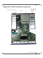
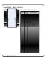
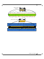
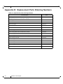
InfiniScale® IV 36-Port QSFP 40 Gb/s
InfiniBand Switch User Manual
P/N: MTS3600Q-1BNC, MTS3600Q-2BNC, MTS3600Q-1UNC, MTS3600Q-2UNC,
MTS3600R-1BNC, MTS3600R-2BNC, MTS3600R-1UNC, MTS3600R-2UNC
Rev 2.7
www.mellanox.com
Rev 2.7
NOTE:
THIS HARDWARE, SOFTWARE OR TEST SUITE PRODUCT (“PRODUCT(S)”) AND ITS RELATED DOCUMENTATION ARE
PROVIDED BY MELLANOX TECHNOLOGIES “AS-IS” WITH ALL FAULTS OF ANY KIND AND SOLELY FOR THE PURPOSE
OF AIDING THE CUSTOMER IN TESTING APPLICATIONS THAT USE THE PRODUCTS IN DESIGNATED SOLUTIONS. THE
CUSTOMER'S MANUFACTURING TEST ENVIRONMENT HAS NOT MET THE STANDARDS SET BY MELLANOX
TECHNOLOGIES TO FULLY QUALIFY THE PRODUCTO(S) AND/OR THE SYSTEM USING IT. THEREFORE, MELLANOX
TECHNOLOGIES CANNOT AND DOES NOT GUARANTEE OR WARRANT THAT THE PRODUCTS WILL OPERATE WITH THE
HIGHEST QUALITY. ANY EXPRESS OR IMPLIED WARRANTIES, INCLUDING, BUT NOT LIMITED TO, THE IMPLIED
WARRANTIES OF MERCHANTABILITY, FITNESS FOR A PARTICULAR PURPOSE AND NONINFRINGEMENT ARE
DISCLAIMED. IN NO EVENT SHALL MELLANOX BE LIABLE TO CUSTOMER OR ANY THIRD PARTIES FOR ANY DIRECT,
INDIRECT, SPECIAL, EXEMPLARY, OR CONSEQUENTIAL DAMAGES OF ANY KIND (INCLUDING, BUT NOT LIMITED TO,
PAYMENT FOR PROCUREMENT OF SUBSTITUTE GOODS OR SERVICES; LOSS OF USE, DATA, OR PROFITS; OR BUSINESS
INTERRUPTION) HOWEVER CAUSED AND ON ANY THEORY OF LIABILITY, WHETHER IN CONTRACT, STRICT LIABILITY,
OR TORT (INCLUDING NEGLIGENCE OR OTHERWISE) ARISING IN ANY WAY FROM THE USE OF THE PRODUCT(S) AND
RELATED DOCUMENTATION EVEN IF ADVISED OF THE POSSIBILITY OF SUCH DAMAGE.
Mellanox Technologies
350 Oakmead Parkway Suite 100
Sunnyvale, CA 94085
U.S.A.
www.mellanox.com
Tel: (408) 970-3400
Fax: (408) 970-3403
Mellanox Technologies, Ltd.
PO Box 586 Hermon Building
Yokneam 20692
Israel
Tel: +972-4-909-7200
Fax: +972-4-959-3245
© Copyright 2011. Mellanox Technologies. All rights reserved.
Mellanox, BridgeX, ConnectX, Virtual Protocol Interconnect, InfiniBlast, InfiniBridge, InfiniHost, InfiniRISC, InfiniScale, and InfiniPCI
are registered trademarks of Mellanox Technologies, Ltd. CORE-Direct, FabricIT, and PhyX are trademarks of Mellanox
Technologies, Ltd. All other trademarks are property of their respective owners.
All other marks and names mentioned herein may be trademarks of their respective companies.
QDR InfiniBand Switch Platform User Manual
2
Mellanox Technologies
Document Number: 2983
QDR InfiniBand Switch Platform User Manual
Rev 2.7
Table of Contents
Table of Contents
3
List of Figures
5
List of Tables
6
Revision History
7
About this Manual
8
Intended Audience
Related Documentation
Conventions
Mellanox Part Numbering Legend
Chapter 1
8
8
9
9
Overview
10
1.1
10
Serial Number and Product Version Information
Chapter 2
Internally Managed vs. Unmanaged (Externally Managed)
12
Chapter 3
Basic Operation and Installation
13
3.1
13
13
17
17
17
18
19
20
20
22
27
27
28
30
31
32
32
3.2
3.3
3.4
3.5
3.6
3.7
Chapter 4
Management and Tools Overview
33
4.1
4.2
33
33
34
34
35
35
35
35
36
39
39
4.3
Chapter 5
Chapter 6
Switch Platform Hardware Overview
3.1.1 Status LEDs
QSFP Cable Power Budget Classification
Interfaces
3.3.1 Port Connector Interfaces
3.3.2 Management and FW updating Interfaces
Package Contents
Switch Platform Installation and Operation
3.5.1 Installation Safety Warnings
3.5.2 Mechanical Installation
3.5.3 Grounding the Switch
3.5.4 Power Connections and Initial Power On
3.5.5 Extracting and Inserting the Power Supply Unit
3.5.6 InfiniBand Cable Installation
3.5.7 Extracting and Inserting the Fan Unit
Disassembly of the Switch from the Rack
Disposal
Network Management and Clustering Software
Internally Managed Switch System
4.2.1 Configuring the Switch for the First Time
4.2.2 Accessing the Switch Locally
4.2.3 Starting a Remote Connection to the Switch
4.2.4 Downloading Firmware
Unmanaged (Externally Managed) Switch
4.3.1 I2C Connector
4.3.2 Updating Firmware
4.3.3 How to Get Mellanox Firmware Tools (MFT)
4.3.4 Open SM
Switch Management Tools
40
5.1
40
Chassis Management
FabricIT Management
41
6.1
41
Downloading FabricIT Software and Documents
Mellanox Technologies
3
Rev 2.7
6.2
Chapter 7
Installing Licenses
6.2.1 Getting the License Key
6.2.2 FabricIT Management and Inspection License
Troubleshooting
41
41
42
43
Appendix A Specification
46
Appendix B Switch Hardware Components
51
Appendix C QSFP Interface
52
Appendix D Replacement Parts Ordering Numbers
54
Appendix E Avertissements de sécurité d’installation (French)
55
Appendix F Installation - Sicherheitshinweise (German)
57
Appendix G Advertencias de seguridad para la instalación (Spanish)
59
Appendix H Special Regulations Regarding Finland, Sweden, Denmark, and Norway
62
4
Mellanox Technologies
QDR InfiniBand Switch Platform User Manual
Rev 2.7
List of Figures
Figure 1:
Generic Product label
10
Figure 2:
Management Module Label
11
Figure 3:
QSFP Switch System Power and Connector Side Panels
13
Figure 4:
Power, Fan, and System LEDs
15
Figure 5:
MTS3600 QSFP Power Side Panel
16
Figure 6:
PSU Status LEDs
16
Figure 7:
Port Numbering
18
Figure 8:
Top and Bottom Ports
18
Figure 9:
Management Interfaces
18
Figure 10: Rack Installation Kit Parts
23
Figure 11: Which Side of the Rack Do You Want the Connectors?
24
Figure 12: Screwing the Rail Slide onto the switch
24
Figure 13: Caged Nut Spacing
25
Figure 14: Screwing in the Rails
25
Figure 15: Which Side of the Rack Do You Want the Connectors?
26
Figure 16: Two Power Inlets - Electric Caution Notifications
28
Figure 17: Power Supply Unit Extraction
29
Figure 18: Top and Bottom Ports
30
Figure 19: Cable connections to the Switch
31
Figure 20: Host Connection
34
Figure 21: License Key Entitlement Number
42
Figure 22: License Key Generation Form
42
Mellanox Technologies
5
Rev 2.7
List of Tables
Table 1:
Revision History Table
7
Table 2:
Reference Documents
8
Table 3:
Part Numbering Legend
9
Table 4:
Switch Management
12
Table 5:
System Status LED Configurations
15
Table 6:
PSU Status LED Configurations
16
Table 7:
Fan Status LED Configurations
17
Table 8:
MTS3600Q Specification Data
46
Table 9:
MTS3600R Specification Data
47
Table 10:
Switch Certification Status
48
Table 11:
InfiniBand QSFP Connector Pinout
52
Table 12:
Replacement Parts Ordering Numbers
54
6
Mellanox Technologies
QDR InfiniBand Switch Platform User Manual
Rev 2.7
Revision History
Table 1 - Revision History Table
Date
Revision
Description
February 2011
Rev 2.7
Updated power numbers.
Changed Grounding section
July 2010
Rev 2.6.1
Added “QSFP Cable Power Budget Classification”
Added active power cable power level in Appendix A Specs
Added “Getting the License Key”
May 2010
Rev 2.6
Updated Section 3.2 to explain the I2C connector use in managed switches.
Added safety warnings in Spanish.
Added Note: ETH Ports Must be 10/100M
November 2009
Rev 2.5
removed reference to dual air flow for MTS3600
August 2009
Rev 2.4
Added that CONSOLE, Ethernet, and USB interfaces do not work in Unmanaged
switches
August 2009
Rev 2.3
Updated Figures 4 and 5. Updated interfaces to reflect CONSOLE interface.
August 2009
Rev 2.2
Updated references to initial start up connecting to a host PC.
August 2009
Rev 2.1
Removed procedure to replace the battery.
June 2009
Rev 2.0
Added Management module label and RS232 DB9 to DB9 harness
Added part numbers for the two management modules.
June 2009
Rev 1.9
Made fixes to management section
added Disassembly instructions
June 2009
Rev 1.8
Added Fabric IT section
April 2009
Rev 1.7
inserted procedure to replace the battery.
April 2009
Rev 1.6
Changes to installation kit and procedure
January 2009
Rev 1.5
added installation instructions
added ECM
Removed Watermark
November 2008
Rev 1.4
fixed weight in specs
October 2008
Rev 1.3
Minor Formatting changes.
September 2008
Rev 1.2
Added Reprogramming the MT3600 Through The I2C Port section.
Added power cord OPNs to table 11 in Appendix D.
September 2008
Rev 1.1
Fixed link to Software package page.
September 2008
Rev 1.0
Initial release
Mellanox Technologies
7
Rev 2.7
About this Manual
This manual describes the installation and basic use of the Mellanox MTS3600 switch, which is
based on the InfiniScale IV InfiniBand switch device.
Intended Audience
This manual is intended for users and system administrators responsible for installing and setting
up the switch platforms listed above.
The manual assumes familiarity with the InfiniBand® Architecture Specification.
Related Documentation
Additional Documentation available from Mellanox:
Table 2 - Reference Documents
Switch Firmware and See
Firmware Update
http://www.mellanox.com > Support > Download Firmware Tools
Tools
Note that the Switch System described in this manual is based on Mellanox
Technologies’ InfiniScale® IV switch device.
Mellanox OFED
Stack for Linux
User’s Manual
See
http://www.mellanox.com > Support > InfiniBand Software and Drivers
Click “Mellanox OpenFabrics Enterprise Distribution for Linux
(MLNX_OFED)”
Select the Linux User’s Manual
The embedded OS and tools on the CPU in the management module is a
subset of the Mellanox OFED stack.
FabricIT Enterprise Talk to your Mellanox representative for information regarding licensing
Fabric Management and implementation of the FabricIT Enterprise Fabric Management SoftSoftware CLI User’s ware System.
Manual
Mellanox Firmware
Tools (MFT)
User’s Manual
Document # 2329
8
The MFT (Mellanox Firmware Tools) package is a set of firmware tools.
The manual supplied with this package provides an overview of the firmware its installation and replacement. The MFT can be downloaded with its
documentation at:
http://www.mellanox.com > Support > Download Firmware Tools
Mellanox Technologies
QDR InfiniBand Switch Platform User Manual
Rev 2.7
Conventions
Throughout this manual, the name MTS3600 and the term switch are used to describe both the 36port QSFP 40Gb/s InfiniBand Switch and the 36-port QSFP 20Gb/s InfiniBand Switch, unless
explicitly indicated otherwise.
Mellanox Part Numbering Legend
Table 3 - Part Numbering Legend
Place
Field
Decoder
MT
Mellanox Technologies
S
System Type
S = Switch
MM
Model
36 = InfiniScale IV
FF
Form factor
00 = Rack mounted switch, 10 = Chassis
C
InfiniBand Port Config.
G = CX4 DDR, J = CX4 QDR, Q = QSFP QDR, R = QSFP DDR,
-
Separator
P
# Power Supplies
0 = 0, 1 = 1, 2 = 2
M
Management
U = Unmanaged, B = Managed
Y
Module Config.
N = IB modules
R
RoHS
C = RoHS w/ Exemption, R = RoHS Lead-Free
Mellanox Technologies
9
Rev 2.7
1
Overview
Overview
Mellanox MTS3600 switch systems provide the highest performing fabric solution by delivering
high bandwidth and low latency to Enterprise Data Centers, High-Performance Computing and
Embedded environments. Networks built with MTS3600 systems can carry converged traffic with
the combination of assured bandwidth and granular quality of service. Built with Mellanox’s 4th
generation InfiniScale® IV InfiniBand switch device, MTS3600 systems provide up to 40Gb/s full
bidirectional bandwidth per port. With 36 ports, these systems are among the densest switching
systems available. These stand-alone switches are an ideal choice for top-of-rack leaf connectivity
or for building small to medium size clusters.
The switch comes pre-installed with all necessary firmware and is configured for standard operation within an InfiniBand fabric. This switch requires an InfiniBand compliant Subnet Manager
running from one of the hosts or Fabric Management software running on the switch. All that is
required for normal operation is to follow the usual precautions for installation and to connect the
switch to the HCAs. Once connected, the Subnet Management software automatically configures
and begins utilizing the switch.
It is recommended that the Mellanox OpenFabrics software package be installed on all nodes connected to the MTS3600. The software package provides a subnet manager and network management tools as well as connectivity software for servers and storage, and is available on the
Mellanox web site. See Chapter 3 for more information.
Basic installation, hot-swapping components and hardware maintenance is covered in “Basic
Operation and Installation” on page 13.
1.1
Serial Number and Product Version Information
The serial number and product version information are found on the label seen in the figure below.
Figure 1: Generic Product label
Also on this label is the GUID identifier for the switch. There is also a label with the MAC for the
management module.
10
Mellanox Technologies
QDR InfiniBand Switch Platform User Manual
Rev 2.7
Figure 2: Management Module Label
Mellanox Technologies
11
Rev 2.7
2
Internally Managed vs. Unmanaged (Externally Managed)
Internally Managed vs. Unmanaged (Externally Managed)
The following table shows which switches come with a management CPU and which do not. Managed switches can be upgraded from simple chassis management to full fabric management by
purchasing an additional license. For more information on buying a license see Section 6.
Unmanaged switches are plug and play out of the box. All switches come with the latest FW
burned on the Flash and EEPROM. Update the FW on unmanaged switches in-band only. When
new FW is available you will receive an email with the link to the Mellanox FW download site.
The download site has the Mellanox FW tool package and full instructions for updating FW.
All managed switches have internal chassis management. Managed switches need an initial configuration before they will start working. See the Installation Guide for initial configuration
instructions. With the purchase of a license this management module can manage the IB fabric.
See Table 4 for details.
Table 4 - Switch Management
Family
MTS3600-UNC
Managed /
Unmanaged
Management Connections
Unmanaged Plug and play
All firmware updates should be done in-band using Mellanox Firmware Management Tools. I2C port access using MTUSB-1 device is
required for firmware updates if in-band burning is not possible.
No Management
MTS3600-BNC
Managed
RS232 cable DB9 to DB9 included in the box to connect to host PC for
initial configuration of the switch. After initial configuration the
switch can be managed through the ethernet using a remote connection.
Chassis Management is included with purchase, and an additional fabric management option, FabricIT-EFM, can be used with purchase of
an additional license.
Should your unmanaged switch have CONSOLE, Ethernet, and USB connectors, they will not
work. Only the I2C connector will work on unmanaged switches.
12
Mellanox Technologies
QDR InfiniBand Switch Platform User Manual
Rev 2.7
3
Basic Operation and Installation
3.1
Switch Platform Hardware Overview
Figure 3 shows the power side panel and connector side panel views of the QSFP switch. The figure shows port configurations for the switch systems, the dual hot-swap power supplies, and hotswap fan module, I2C connector, USB connectors, Ethernet port connector, RS232 DB9 connector, and various status LEDs. Unmanaged switches have an I2C DB9 connector.
Figure 3: QSFP Switch System Power and Connector Side Panels
Power Side panel
I2C
OK
!
19
20
21
22
23
24
25
26
27
OK
System
Fans
PSU 1
PSU 2
CONSOLE
28
29
30
31
32
33
34
~AC
35
36
MTS3600
InfiniBand
Switch
1
2
3
4
5
6
7
8
9
10
11
12
13
14
15
16
17
18
Connector Side Panel
All InfiniBand connectivity is via the connector side panel. All connectors can support active
cables.
3.1.1 Status LEDs
3.1.1.1
System Status Indicators
The System Status Indicators are located just to the left of the primary power supply unit, and
labeled “System.” .
The system status indicators should display as follows:
• When the switch is plugged in, within three minutes the STATUS LED should light up green.
• The PSU LED for the plugged in PSU should light up green.
• The PSU LED for the second PSU should light up green only if a second PSU is installed in the
switch for redundancy and Hot-Swap ability and it is connected to a power source. If two PSUs
are installed and only one PSU is connected to a power supply the second PSU LED will be red.
If only one PSU is installed in the switch, the second PSU LED will be off.
Mellanox Technologies
13
Rev 2.7
Basic Operation and Installation
As long as there is power to the switch (one PSU is connected), and the switch is booted
up and running, the status LED will be green.
• The FAN LED should light up green.
If the STATUS LED shows red after three minutes unplug the switch and call your
Mellanox representative for assistance.
If the FAN LED shows red, troubleshoot the fan module.
If the switch shuts down due to over temperature, unplug the switch, wait 5 minutes
and replug in the switch. For more information See “Troubleshooting” on page 43.
If the PSU LEDs are not green, this indicates a problem with the power supplies. Only run the
switch if at least one of the PSU LEDs is green.
14
Mellanox Technologies
QDR InfiniBand Switch Platform User Manual
Rev 2.7
Figure 4: Power, Fan, and System LEDs
Latch release mechanism
Handle
DC output from
the PSU is OK
System Status Indicators
There is a fault
in the PSU
Switch Fan Status
Indicators
Input AC voltage is
good
PSU Status Indicators
Table 5 - System Status LED Configurations
LED Configuration
Status
OK – The system is up and running.
Green
Off
Error –A fault in the system.
Off
Yellow
Off – The system has no power.
Off
3.1.1.2
Off
Power Supply Status Indicators
The MTS3600 36 Port Switch is available with one or two factory installed Power Supply Units.
For switches with only one unit installed, a second Power Supply Unit can be added to increase
Mellanox Technologies
15
Rev 2.7
Basic Operation and Installation
security, hot-swap ability and to add redundancy. See Section D, “Replacement Parts Ordering
Numbers,” on page 54 for ordering part numbers.
Figure 5: MTS3600 QSFP Power Side Panel
Place for secondary
Power Supply Unit
Primary Power
Supply Unit
Fan Unit
The primary power supply unit (PSU1) is located on the right side of the power side panel, with
PSU2 on the left side.Status indicators are located to the left of the primary power supply unit.
Each PSU also has three status LEDs on the right side of the PSU, that indicate the internal status
of the unit.
Figure 6: PSU Status LEDs
OK
~AC
Table 6 - PSU Status LED Configurations
LED Configuration
~AC
Status
This LED when lit indicates input voltage between
100 and 240 Volts.
This LED when lit indicates a fault in the power supply.
OK
This LED when lit indicates that the output
from the power supply is +12VDC.
Figure 4 on page 15 shows the explanation of the PSU Status LED colors.
3.1.1.3
Fan Status Indicators
The indicator labeled “Fans” is located just to the left of the primary power supply unit, next to
PSU 1. The following fan status conditions are possible:
16
Mellanox Technologies
QDR InfiniBand Switch Platform User Manual
Rev 2.7
Table 7 - Fan Status LED Configurations
LED Configuration
Status
OK – All fans are operating.
Green
Off
Error – One or more fans is not operating. Repair or
replace the fan unit.
Off
Yellow
Off – The fan unit is not receiving any power.
Check that the fan unit is properly and completely
inserted.
Off
Off
All fans must be operating while the power supply is plugged in.
If the switch shuts down due to over temperature, unplug the switch, wait 5
minutes and replug in the switch. For more information See “Troubleshooting”
on page 43.
3.2
QSFP Cable Power Budget Classification
All MTS3600 QSFP switches are designed for a active cables with a max power per module of
3.5W. This is power level 4 according to the QSFP Public Specification.
3.3
Interfaces
3.3.1 Port Connector Interfaces
3.3.1.1
36 Port Switches
The Connector side of the switch has 36 QSFP ports. These are placed in two rows, 18 ports to a
row. The ports are labelled as shown in Figure 7. The bottom row ports are flipped from the top
row. See Figure 8 for bottom row - top row port orientation.
Mellanox Technologies
17
Rev 2.7
Basic Operation and Installation
Figure 7: Port Numbering
19
20
21
22
23
24
25
26
27
28
30
29
31
32
33
34
35
36
MTS3600
InfiniBand
Switch
1
3.3.1.2
2
3
4
5
6
7
8
9
10
11
12
13
14
15
16
17
18
Top and Bottom Orientation
Figure 8: Top and Bottom Ports
3.3.2 Management and FW updating Interfaces
There are five interfaces to connect to the MTS3600. They are:
• 1 I2C DB9 interface is labelled “I2C”. On managed switches this interface is a service interface
only.
Do not use the I2C DB9 interface to update the FW in the managed switches.
Update FW in managed switches by using FabricIT™ EFM Web User Interface (WebUI) or FabricIT™ EFM Command Line Interface (CLI).
• 1 Ethernet connector is labelled
. Use this connector to connect to the Ethernet for remote
management. This connector does not work in unmanaged switches.
• 2 USB ports are labelled
. These connectors do not work in unmanaged switches.
• 1 serial CONSOLE port. Use this to connect to a local host PC. This connector does not work in
unmanaged switches.
Figure 9: Management Interfaces
I2C
CONSOLE
18
Mellanox Technologies
OK
!
System
Fans
PSU 1
PSU 2
QDR InfiniBand Switch Platform User Manual
3.3.2.1
Rev 2.7
Serial CONSOLE Interface
The port labelled “CONSOLE” is for a local host connection to the management module. This is
used the first time the switch is connected. Connecting to a local host PC and following the
instructions in the Installation Guide, “Configuring the Switch for the First Time”, must be done
before any remote management is available. This connector does not work in unmanaged (externally managed) switches.
All firmware updates should be done in-band using Mellanox Firmware Management Tools.
3.3.2.2
RJ-45 Ethernet Connector
The Ethernet connection
provides access for remote management.
Each Ethernet connector gets connected to Ethernet switches. These switches
must be configured to 10/100M auto-negotiation.
This connector does not work in unmanaged (externally managed) switches.
3.3.2.3
I2C Connector
The I2C connection provides access to Flash and EEPROMs.
This connector is for use on unmanaged switches only. On unmanaged switches this connector is
used to update FW.
The unmanaged switches are Plug and Play and all firmware updates should be
done in-band. The I2C connection should only be used if the FW image was
corrupted to the point that the regular FW tools cannot successfully reburn the
correct image.
Do not use this connector on managed switches.
Do not use the I2C DB9 interface to update the FW in the managed switches.
Update FW in managed switches by using FabricIT™ EFM Web User Interface (WebUI) or FabricIT™ EFM Command Line Interface (CLI).
3.4
Package Contents
Before you install your new MTS3600 switch, unpack the system and check to make sure that all
the parts have been sent, check this against the parts list. Check the parts for visible damage that
may have occurred during shipping.
Mellanox Technologies
19
Rev 2.7
Basic Operation and Installation
The switch comes packed with the following items:
• 1) switch
• 1) power cable for each PSU– Type B 6ft US 125V 10A chord. See “Replacement Parts Ordering Numbers” on page 54. to order power cords for various countries. A single power cord for
each power supply unit can be ordered at no extra charge.
• 1) rail kit;MTR003600
• 1) harness; HAR000017 or HAR000040
• 1) CD
• 1) Quick Start Guide
• 1) Installation Guide
Note: If anything is damaged or missing, contact your customer representative immediately.
3.5
Switch Platform Installation and Operation
Installation and initialization of the switch platform are straightforward processes, requiring attention to the normal mechanical, power, and thermal precautions for rack-mounted equipment.
The unmanaged (externally managed) switch platform does not require any programming or configuration to operate as a basic InfiniBand switch and includes all of the necessary functionality to
operate with external standard InfiniBand Subnet Management software.
The managed switch platform requires initial configuration to operate as an InfiniBand switch. An
Internal Management option is available for the switch platform which includes InfiniBand Subnet
Management software embedded internally in the switch. This section describes the installation
process and basic operation of the switch platform. Please first read the warnings sub-section carefully before carrying on with installation procedures.
3.5.1 Installation Safety Warnings
For Safety Warnings in French see Section E,“Avertissements de sécurité d’installation (French),”
on page 55, for German see Section F,“Installation - Sicherheitshinweise (German),” on page 57,
and for Spanish see Section G,“Advertencias de seguridad para la instalación (Spanish),” on page
59.
For special regulations regarding Finland, Sweden, Denmark, and Norway see Section H,“Special
Regulations Regarding Finland, Sweden, Denmark, and Norway,” on page 62.
1. Installation Instructions
Read all installation instructions before connecting the equipment to the
power source.
20
Mellanox Technologies
QDR InfiniBand Switch Platform User Manual
Rev 2.7
2. Over-temperature
This equipment should not be operated in an area with an ambient temperature exceeding the maximum recommended: 45°C (113°F). Moreover, to guarantee proper air flow, allow at least 8cm (3 inches) of
clearance around the ventilation openings.
3. Stacking the Chassis
The chassis should not be stacked on any other equipment. If the chassis
falls, it can cause bodily injury and equipment damage.
4. Redundant Power Supply Connection - Electrical Hazard
This product includes a blank cover over the space for the redundant
power supply. Do not operate the product if the blank cover is not
securely fastened or if it is removed.
5. During Lightning - Electrical Hazard
During periods of lightning activity, do not work on the equipment or
connect or disconnect cables.
6. Copper InfiniBand Cable Connecting/Disconnecting
Copper InfiniBand cables are heavy and not flexible, as such they should
be carefully attached to or detached from the connectors. Refer to the
cable manufacturer for special warnings and instructions.
7.
Rack Mounting and Servicing
When this product is mounted or serviced in a rack, special precautions
must be taken to ensure that the system remains stable. In general you
should fill the rack with equipment starting from the bottom to the top.
8. Equipment Installation
This equipment should be installed, replaced, or serviced only by trained
and qualified personnel.
Mellanox Technologies
21
Rev 2.7
Basic Operation and Installation
9. Equipment Disposal
Disposal of this equipment should be in accordance to all national laws
and regulations.
10. Local and National Electrical Codes
This equipment should be installed in compliance with local and national
electrical codes.
3.5.2 Mechanical Installation
The switch platform can be rack mounted and is designed for installation in a standard 19” rack.
The power side of the switch includes a hot-swap power supply module, a blank cover for an
optional second PSU for redundancy, a hot-swap fan tray, system LEDs, and management connection ports. The connector side of the switch has the QSFP ports.
The switch platform contains auto-sensing 100 - 240 VAC connections for all possible PSUs.
The installer should use a rack capable of supporting the mechanical and environmental characteristics of a fully populated platform.
The rack mounting holes conform to the EIA-310 standard for 19-inch racks.
Take precautions to guarantee proper ventilation in order to maintain good airflow at ambient temperature. Cable routing in particular should not impede the
air exhaust from the chassis.
This switch can be installed in any standard 19”racks with depths of 670mm to 900mm.
3.5.2.1
Installing the Switch in the Rack
Tools and Customer Supplied Parts
• Phillips Screwdrivers #1 and #2
• ESD strap
• ESD mat
• grounding screw
• grounding wire sufficient to reach a valid ground.
Parts included in the installation kit:
• 2 rails
• 2 rail slides
• 8 pan head screws M6
22
Mellanox Technologies
• 8 recessed flat head screws
• 4 caged nuts
• 2 metal washers
QDR InfiniBand Switch Platform User Manual
Rev 2.7
Figure 10: Rack Installation Kit Parts
rail
rail slide
Before you install your new MTS3600 switch, unpack the system and check to make sure that all
the parts have been sent, check this against the parts list. Check the parts for visible damages that
may have occurred during shipping.
If anything is damaged or missing, contact your customer representative
immediately.
Procedure
1.
2.
Place the ESD mat on the floor where you will be working and put on the ESD strap. Make
sure the ESD strap is touching your skin and that the other end is connected to a verified
ground.
Choose which side of the switch you want even with the vertical rack support. Either the side
with the power supply units or the side with the IB connectors can be even with the vertical
rack support. The other side of the switch will be further inside of the rack.
Things to consider before choosing where to mount the rails and rail slides.
Mellanox Technologies
23
Rev 2.7
Basic Operation and Installation
Figure 11: Which Side of the Rack Do You Want the Connectors?
The distance between the rack and the door can be as little as 4 cm on one side of the rack and as
much as 18 cm on the other side of the rack. Keep in mind that there can be as many as 36 cables
connected to the switch.
•Do you want the connector side recessed in the rack to allow for larger cable bending
radius?
•Will the connector side be recessed past other equipment in the rack and will this be problematic?
The rails are to be installed on the side of the rack where the switch will be
recessed into the rack
3.
Install the rail slides onto the switch. Place the end of the rail slide with the 90o angle on the
side of the switch that you want to be even with the vertical support of the 19” rack. Use four
of the flat head screws for each rail slide. There are two sets of holes in the rail slide. Select
the set of holes to either mount the switch closer or farther away from the rack vertical support. Tighten the screws to 3Nm or 26.5 pound inches.
Figure 12: Screwing the Rail Slide onto the switch
This side of the
switch will be next
to the vertical rack
support.
24
Mellanox Technologies
QDR InfiniBand Switch Platform User Manual
4.
Rev 2.7
Clip the nuts into the holes in the rack you will be using to connect the rail slides. Check that
both sides of the switch are in the same position number on the rack.
Figure 13: Caged Nut Spacing
The caged nuts are
separated by a single space
5.
Using two of the pan head screws and one washer, for each rail, install the rails to the other
end of the rack. Place the rail behind the holes in the rack and screw the screws through the
holes in the washer then through the rails. Tighten the pan head screws that hold the rails to
9.2 Nm or 81.5 pound inches.
Figure 14: Screwing in the Rails
6.
7.
8.
9.
10.
11.
12.
Place the four bolts for the caged nuts within reach.
Slide the switch into the rails.
Put the switch into place and screw the bolts into the nuts from step 4. Tighten the bolts to
9.2 Nm or 81.5 pound inches.
Tighten all of the screws.
Plug in the power cables.
Check the Status LEDs and confirm that all of the LEDs show status lights consistent with
normal operation.
You can start connecting all of the cables to the switch.
Make sure that the Rail kit is compatible with your rack.
Mellanox Technologies
25
Rev 2.7
Basic Operation and Installation
Figure 15: Which Side of the Rack Do You Want the Connectors?
…
…
…
.
…
…
…
.
The figure above shows the power side next to the door and the connector side away from the door. This
configuration has more room for the cables and a larger bending radius.
The figure below shows the connector side next to the door and the power side away from the door.
This configuration may be necessary to conform to your rack configuration.
…
…
…
.
Warning: Any yellow status LEDs is cause for concern and must be
dealt with immediately.
It can take up to 3 minutes to boot up, during which time the status LED
may indicate red.
26
Mellanox Technologies
…
…
…
.
QDR InfiniBand Switch Platform User Manual
Rev 2.7
3.5.3 Grounding the Switch
Check to determine if your local or national electrical codes require an external ground to all IT
components. If so, connect a ground wire to one of the casing screws and connect the other end to
a valid ground. If you choose to not use the ground screw, make sure that the rack is properly
grounded and that there is a valid ground connection between the chassis of the switch and the
rack. Test the ground using an Ohm meter.
Some national and/or local codes may require IT components to be bonded and externally grounded (not including the power cord ground). You must follow all national and
local codes when installing this equipment.
3.5.4 Power Connections and Initial Power On
The switch platform ships with one or two Power Supply Units. For switches with only one unit
installed, a second PSU may be installed at a later time. Each supply has a separate AC receptacle.
The input voltage is auto-adjusting for 100 - 240 VAC, 50-60Hz power connections. The power
cords should be standard 3-wire AC power cords including a safety ground and rated for 15A or
higher.
Caution: The switch platform will automatically power on when AC power is
applied. There is no power switch. Check all boards, power supplies, and fan
tray modules for proper insertion before plugging in a power cable.
Caution: After inserting a power cable and confirming the green system status
LED light is on; make sure that the Fan Status indicator shows green.
If the fan status indicator is not green then unplug the power connection and
check that the fan module is inserted properly and that the mating connector of
the fan unit is free of any dirt and/or obstacles.
Caution: When turning off the switch, make sure ALL LEDS are off to ensure
a powered down status.
Mellanox Technologies
27
Rev 2.7
Basic Operation and Installation
Do not hot swap the power supply if your switch has only one power supply.
You must power down the system to replace the power supply unit when there
is only one PSU in the switch.
Figure 16: Two Power Inlets - Electric Caution Notifications
CAUTION
Risk of electric shock and energy
hazard. The two PSUs are independent.
Disconnect all power supplies to
ensure a powered down state inside
of the switch platform.
ACHTUNG
Gafahr des elektrischen
Schocks. Entferrnen des
Netzsteckers elnes Netzteils
spannungsfrei. Um alle Einhieten spannungsfrei zu machen
sind die Netzstecker aller
Netzteile zu entfernen
ATTENTION
Risque de choc et de danger
e’lectriques. Le de’branchment
d’une seule alimentation stabilise’e ne de’branch uniquement
qu’un module “Alimentation Stabilise’e”. Pour isoler completement le module en cause, Il faut
de’brancher toutes les alimentations stabilise’es.
3.5.5 Extracting and Inserting the Power Supply Unit
With both power supplies installed in the redundant configuration, either PSU may be extracted
without bringing down the system.
Make sure that the PSU that you are NOT replacing is showing all green, for
both the PSU and status indicators.
28
Mellanox Technologies
QDR InfiniBand Switch Platform User Manual
Rev 2.7
Figure 17: Power Supply Unit Extraction
To extract a PSU:
1.
2.
3.
Remove the power cord from the power supply unit.
Grasping the handle with your right hand, push the latch release with your thumb while pulling the handle outward. As the PSU unseats, the PSU status indicators will turn off.
Remove the PSU.
To insert a PSU:
1.
Make sure the mating connector of the new unit is free of any dirt and/or obstacles.
Do not attempt to insert a PSU with a power cord connected to it.
2.
3.
4.
5.
Insert the PSU by sliding it into the opening until a slight resistance is felt.
Continue pressing the PSU until it seats completely. The latch will snap into place confirming the proper installation.
Insert the power cord into the supply connector.
Insert the other end of the power cord into an outlet of the correct voltage.
The green PSU indicator should light and the yellow indicator should remain
off. If not, repeat the whole procedure to extract the PSU and re-insert it.
Mellanox Technologies
29
Rev 2.7
Basic Operation and Installation
3.5.6 InfiniBand Cable Installation
All cables can be inserted or removed with the unit powered on. To insert a cable, press the connector into the port receptacle until the connector is firmly seated. The GREEN LED indicator,
corresponding to each QSFP port, will light when the physical connection is established (that is,
when the unit is powered on and a cable is plugged into the port with the other end of the connector plugged into a functioning port). After plugging in a cable, lock the connector using the latching mechanism particular to the cable vendor. When a logical connection is made the yellow light
will come on. When data is being transferred the yellow light will blink.
Cables in the bottom row should be inserted up side down in relation to the
how the cables are inserted in the top row.
Figure 18: Top and Bottom Ports
To remove, disengage the locks and slowly pull the connector away from the port receptacle. Both
LED indicators will turn off when the cable is unseated.
Care should be taken not to impede the air exhaust flow through the ventilation holes next to the
InfiniBand ports. Cable lengths should be used which allow for routing horizontally around to the
side of the chassis before bending upward or downward in the rack.
30
Mellanox Technologies
QDR InfiniBand Switch Platform User Manual
Rev 2.7
Figure 19: Cable connections to the Switch
3.5.7
Extracting and Inserting the Fan Unit
This switch can operate indefinitely with one of the three fans in the fan module inoperable so long
as the ambient temperature is below 45° Celsius.
Operation without a fan unit should not exceed two minutes.
During fan hot-swap, if both indicators are OFF then the fan unit is disconnected.
To extract a Fan Unit
1.
2.
Loosen the two thumb screws locking the fan tray in place.
One of the fan status indicators (either green or yellow) will remain on.
Pull the fan unit out by pulling on the thumbscrews. As the fan unseats, the fan status indicator will turn off.
To insert a FAN Unit:
1.
2.
Make sure the mating connector of the new unit is free of any dirt and/or obstacles.
Insert the fan unit by sliding it into the opening until slight resistance is felt. Continue pressing the fan unit until it seats completely.
Mellanox Technologies
31
Rev 2.7
Basic Operation and Installation
3.
Turn the two thumb screws to lock the fan unit in place.
The green fan status indicator should light and the yellow fan status should
remain off. If not, extract the fan unit and reinsert it. After two unsuccessful
attempts to install the fan unit, power off the switch before attempting any system debug.
3.6
Disassembly of the Switch from the Rack
To disassemble the switch from the rack:
1.
2.
3.
4.
Unplug and remove all connectors.
Unplug all power cords.
Remove the ground wire.
Unscrew the 4 bolts from the side of the switch with the rail slides.
Support the weight of the switch when you remove the screws so that the
switch does not fall.
5.
6.
7.
3.7
Slide the switch from the rack.
Remove the rails from the rack.
Remove the eight caged nuts.
Disposal
For proper disassembly instructions to comply with the WEEE Directive 2002/96/EC see the Mellanox website.
According to the WEEE Directive 2002/96/EC, all waste electrical and
electronic equipment (EEE) should be collected separately and not disposed of with regular household waste.
Dispose of this product and all of its parts in a responsible and environmentally friendly way.
32
Mellanox Technologies
QDR InfiniBand Switch Platform User Manual
4
Rev 2.7
Management and Tools Overview
The Ethernet ports for remote management connect to Ethernet switches.
These switches must be configured to 10/100M auto-negotiation.
4.1
Network Management and Clustering Software
Download and install, on all nodes, the Mellanox OpenFabric software package for Linux, Windows, or other operating systems from the Mellanox software website:
http://www.mellanox.com.=> Downloads => InfiniBand SW/Drivers.
This software package provides connectivity for server and storage systems utilizing High Performance Computing (HPC) or enterprise data center (EDC) applications across an InfiniBand fabric.
It also provides a subnet manager for simple network configuration and network administration
and diagnostic tools for network management.
4.2
Internally Managed Switch System
The management module runs SW that manages the switch chassis. An optional licensing fee will
allow you to manage the whole fabric up to 108 nodes with the chassis management module. See
your Mellanox representative for information and pricing regarding this upgrade.
Management modules will have the capability to allow remote monitoring and remote management of the chassis from any host connected to the fabric.
The managed switch system includes a CPU which contains:
• embedded OS, secure in-band, out-band access
• chassis manager and system BIST
• SNMP agent, 3rd party tool integration
• GUI
• subnet manager
• performance/provisioning manager
• congestion and notification manager
• QoS manager
• adaptive routing manager
• cluster diagnostics manager
The Subnet management features include:
• upgrading drivers
Mellanox Technologies
33
Rev 2.7
Management and Tools Overview
• upgrading software
• monitoring of:
•AC power to the PSUs
•DC power out from the PSUs
•board temperature
•fan module unit
•failure in the switch system
•system failure in the switch system
• querying for board serial numbers and their revisions
In addition, the tools enable firmware management capabilities such as:
• querying for existing firmware versions
• burning new firmware (from scratch or for recovery from damaged firmware)
• querying for and changing system GUIDs
• checking for duplicate or bad GUIDs
4.2.1 Configuring the Switch for the First Time
Unmanaged (Externally managed) switches, that is the MTS 3600-UNC do not
get configured. On unmanaged switches, the CONSOLE, Ethernet, and USB
connectors do not work.
See the Installation Guide of the MTS3600 switch, “Configuring the Switch for the First Time”.
The port labelled CONSOLE must be connected to a local host PC. This must be used the first
time the switch is connected. This must be done before any remote management is available.
4.2.2 Accessing the Switch Locally
For local access out of band management of the switch system use the two procedures below Section 4.2.2.1 for initial configuration and Section 4.2.3 to start a remote connection.
4.2.2.1
Accessing the CPU via a host PC
Hook up the supplied harness cable (HAR00040) from the connector labelled CONSOLE to the
DB9 connector of the local host PC.
Figure 20: Host Connection
Connect the host PC to here
I2C
CONSOLE
34
Mellanox Technologies
OK
!
System
Fans
PSU 1
PSU 2
OK
~AC
QDR InfiniBand Switch Platform User Manual
8.
Rev 2.7
Follow the instructions in the Installation guide Rev 1.3 “Configuring the Switch for the
First Time”
4.2.3 Starting a Remote Connection to the Switch
4.2.3.1
Accessing the CPU via the Ethernet Connector
Once the initial configuration is completed the management tools can be accessed through:
• SSH
• Telnet
• the WEB
4.2.4 Downloading Firmware
Firmware for this switch system can be found at and downloaded from:
http://www.mellanox.com => Downloads => Firmware.
Be sure to read and follow all of the instructions regarding the updating of the firmware on your
switch system. Firmware for the HCA cards connected to this switch system can be downloaded
from the same site.
4.3
Unmanaged (Externally Managed) Switch
4.3.1 I2C Connector
The I2C connection provides access to Flash and EEPROMs. This connection allows access to the
switch for updating FW when in-band FW updating is impossible.
Unmanaged (Externally managed) switches, that is the MTS 3600-UNC do not get configured. On
unmanaged switches, the CONSOLE, Ethernet, and USB connectors do not work.The I2C connector should only be used when the FW cannot be updated in-band.
The unmanaged switches are Plug and Play and all firmware updates should be
done in-band. The I2C connection should only be used if the FW image was
corrupted to the point that the regular FW tools cannot successfully reburn the
correct image.
When you install the switch, it comes with the latest firmware burned on the board. All firmware
updates should be done in-band. This is only done when you receive an email that a newer FW
version for your switch is available. Download the latest FW from
http://www.mellanox.com => Downloads => Firmware. For instructions on downloading FW see
http://www.mellanox.com => Downloads => Firmware Tools. Be sure to download the user manual appropriate to your OS. Read the instructions in the User manual for the FW update procedure.
Mellanox Technologies
35
Rev 2.7
Management and Tools Overview
4.3.2 Updating Firmware
The switch is delivered with the latest Firmware available at the time of production. New firmware
versions will be posted on the Mellanox firmware download page:
http://www.mellanox.com => Downloads => Firmware.
You will need the Mellanox Firmware Tools package available in the Mellanox OpenFabrics software package, to update firmware for this switch. It can also be downloaded from:
http://www.mellanox.com. => Downloads => InfiniBand SW/Drivers.
You will also need to download and unzip the firmware binary image. This is provided in the Mellanox Web site at: http://www.mellanox.com => Downloads => Firmware and go to the InfiniScale
IV Switch systems. Click in the Table for the FW image that you need.
4.3.2.1
Instructions for Reprogramming Over the InfiniBand Network
To update an InfiniScale IV switch device having a specific GUID (for example,
0x00000006660abcd0) or LID, the following are the recommended steps to update the device
firmware.
1.
Make sure all subnet ports are in the active state. One way to check this is to run opensm, the
Subnet Manager.
[root@mymach]> /etc/init.d/opensmd start
opensm start
[ OK ]
2.
Make sure the local ports are active by running ‘ibv_devinfo’.
3.
Obtain the device LID. There are two ways to do that:
I. Using the “mst ib add” command:
The “mst ib add” runs the ibdiagnet tool to discover the InfiniBand fabric and then lists the discovered IB nodes as
an mst device under /dev/mst/ directory. These devices can be used for access by other MFT tools.
[root@mymach]> mst ib add
-I- Running ibdiagnet to discover the fabric ...
Loading IBDIAGNET from: /usr/local/lib/ibdiagnet1.2
-W- Topology file is not specified.
Reports regarding cluster links will use direct routes.
Loading IBDM from: /usr/local/lib/ibdm1.2
-I- Using port 1 as the local port.
-I- Discovering ... 3 nodes (2 Switches & 1 CA-s) discovered.
-I---------------------------------------------------I- Bad Guids/LIDs Info
-I--------------------------------------------------36
Mellanox Technologies
QDR InfiniBand Switch Platform User Manual
Rev 2.7
-I- skip option set. no report will be issued
-I---------------------------------------------------I- Links With Logical State = INIT
-I---------------------------------------------------I- skip option set. no report will be issued
-I---------------------------------------------------I- PM Counters Info
-I---------------------------------------------------I- skip option set. no report will be issued
-I---------------------------------------------------I- Fabric Partitions Report (see ibdiagnet.pkey for a full hosts list)
-I---------------------------------------------------I- skip option set. no report will be issued
-I---------------------------------------------------I- IPoIB Subnets Check
-I---------------------------------------------------32
-I- skip option set. no report will be issued
-I---------------------------------------------------I- Bad Links Info
-I---------------------------------------------------I- No bad link were found
----------------------------------------------------------------I- Stages Status Report:
STAGE
Errors Warnings
Bad GUIDs/LIDs Check
0
0
Link State Active Check
0
0
Performance Counters Report
0
0
Mellanox Technologies
37
Rev 2.7
Management and Tools Overview
Partitions Check
0
0
IPoIB Subnets Check
0
0
Please see /tmp/ibdiagnet.log for complete log
----------------------------------------------------------------I- Done. Run time was 1 seconds.
-I- Added 3 in-band devices
[root@mymach]>
To list the discovered mst inband devices run “mst status”.
[root@mymach]> mst status
MST modules:
-----------MST PCI module loaded
MST PCI configuration module loaded
...
Inband devices:
------------------/dev/mst/CA_MT25418_sw005_HCA-1_lid-0x0001
/dev/mst/SW_MT47396_lid-0x0011
/dev/mst/SW_MT48438_lid-0x0003
[root@mymach]>
II. Using the ibnetdiscover tool:
Run:
[root@mymach]# ibnetdiscover | grep 00000006660abcd0 | grep -w Switch
Switch 24 "S-00000006660abcd0"
base port 0 lid 17 lmc 0
38
Mellanox Technologies
"MT47396 Infiniscale-III Mellanox Technologies"
QDR InfiniBand Switch Platform User Manual
Rev 2.7
Note: The resulting LID is given as a decimal number.
4.
Run mlxburn with the LID retrieved in step #3 above to perform the In-Band burning operation.
Burn the InfiniScale IV switch:
[root@mymach]> mlxburn -d /dev/mst/SW_MT48438_lid-0x0003 -fw ./fw-IS4.mlx -qq
-I- Querying device ...
-I- Using auto detected configuration file: ./MTS3600Q-1UNC_A1.ini (PSID
=
MT_0C20110003)
-I- Generating image ...
*** WARNING *** Running quick query - Skipping full image integrity checks.
Current FW version on flash: 7.0.135
New FW version:
7.0.138
Burning second FW image without signatures - OK
Restoring second signature
- OK
-I- Image burn completed successfully.
4.3.3 How to Get Mellanox Firmware Tools (MFT)
Mellanox Firmware Tools (MFT) and documentation are available for download via
http://www.mellanox.com > Downloads > Firmware Tools.
The MFT kit includes:
• mlxburn
• flint
• spark
• IBspark
• debug utilities
See “Related Documentation” on page 7.
4.3.4 Open SM
To manage the Mellanox switch system using OFED, download Mellanox Open Fabrics from
http://www.mellanox.com > Downloads > InfiniBandSW/Drivers.
Be sure to read and follow all of the instructions regarding the installation and use of these tools.
Mellanox Technologies
39
Rev 2.7
5
Switch Management Tools
Switch Management Tools
This chapter describes the management tools. The management module allows the switch to be
managed either locally or remotely. The switch can also be managed using Out-of-Band management of the switch via FabricIT EFM. The managed switch comes with a module that will completely manage your switch. An optional management module in combination with the licensing
fee for full access to the FabricIT EFM software can manage a fabric of up to 2000 nodes.
5.1
Chassis Management
The chassis manager will give the user access to:
• switch temperatures
• power supply voltages
• fan unit information
• power unit information
• Flash memory
The manager also has the ability to burn new FW on the switch.
40
Mellanox Technologies
QDR InfiniBand Switch Platform User Manual
6
Rev 2.7
FabricIT Management
FabricIT EFM is a software based management system that can be run with either a command line
interface or with a GUI interface. The GUI interface can be run through the Web. A license is
required for full use of FabricIT. The standard management module, without a license, allows for
managing the switch using the Web interface or the command line interface and software supplied
on the management chip. Make sure to register your FabricIT license to enable all of the available
commands and functions.
See the FabricIT EFM User Manual for instructions and commands available to manage the
switches and fabric.
6.1
Downloading FabricIT Software and Documents
To download FabricIT software and documentation, please visit the following Web page:
FabricIT http://www.mellanox.com/content/pages.php?pg=fabric_it_login.
Note that you will need to enter the License Entitlement number and the Switch S/N to obtain the
software and documentation, and also to generate an EFM license that enables extended FabricIT
management and inspection features on your switch system.
6.2
Installing Licenses
A license for extended FabricIT management and inspection features with FabricIT EFM software
is available for an additional licensing fee.
6.2.1 Getting the License Key
FabricIT Enterprise Fabric Manager (EFM) license can be purchased from your Mellanox representative at any time. A License Enablement Number will be supplied at the time of purchase. To
generate the License Key enter the License Enablement Number and the Switch Serial Number
into the Mellanox online license tool at http://license.mellanox.com. The Switch Serial Number
can be found on the pull-out tab or the box labeling. For the serial number location on the chassis
see Section 1.1, “Serial Number and Product Version Information,” on page 10.
Mellanox Technologies
41
Rev 2.7
FabricIT Management
Figure 21: License Key Entitlement Number
Figure 22: License Key Generation Form
6.2.2 FabricIT Management and Inspection License
If your switch system includes an internal management module, then to activate extended FabricIT
management and inspection features you need to install the license that was purchased along with
the switch system. Without the license, you will not be able to run a Subnet Manager on the switch
nor run advanced fabric diagnostics.
For information on installation, please refer to the FabricIT Enterprise Fabric Management Software CLI User’s Manual.
42
Mellanox Technologies
QDR InfiniBand Switch Platform User Manual
7
Rev 2.7
Troubleshooting
As soon as a switch is plugged in make sure that the green power LEDs on the PSUs are on.
Status LED and or Status Health LED
If either of these two LEDs is red unplug the switch and call your Mellanox representative.
Power supply unit:
If the ~AC power LED is off, check that the power cable is plugged into a working outlet.
1.
2.
3.
4.
Check that the power cable has a voltage within the range of 100 - 240 volts AC.
If the LED on the PSU is not lit or is red.
Remove and reinstall the power cable.
Remove and reinstall the PSU.
5.
If the ~AC power LED is green but the OK power LED is off or the
Replace the PSU.
LED is on –
The Status green power LED for PSU1 or PSU2 does not come on:
1.
2.
3.
4.
5.
If the OK LED on the PSU is on but the system LED is off remove and reinstall the PSU.
Make sure the mating connector of the new unit is free of any dirt and/or obstacles.
If the OK LED on the PSU is off, check if the PSU System LED is on.
Remove and reinstall the power cable. Check that the power outlet (in the wall) is working.
Remove and reinstall the PSU. Make sure the mating connector of the new unit is free of any
dirt and/or obstacles.
Replace the PSU.
The power LED for the switch shuts off:
1.
Check that the there is adequate ventilation. Are the fan LEDs showing that the fans are all
up and running?
2.
Make sure that there is nothing blocking the front or rear of the chassis and that the fan modules and ventilation holes are not blocked (especially dust over the holes).
3.
If you find dust blocking the holes it is recommended to clean the fan unit and remove the
dust from the front and rear panels of the switch using a vacuum cleaner.
The green power LED for the fans does not come on:
1.
Check that the Power LEDs are on.
Mellanox Technologies
43
Rev 2.7
Troubleshooting
2.
Remove and reinstall the fan unit. Make sure the mating connector of the new unit is free of
any dirt and/or obstacles. See Section 3.5.7, “Extracting and Inserting the Fan Unit,” on
page 31.
Caution: Do not run the switch if the System Status LED for the Fans is Yellow!
The link LED for the InfiniBand connector does not come on:
1.
2.
3.
4.
Check that both ends of the cable are connected.
Check that the locks on the ends are secured.
Make sure that the latest FW version is installed on both the HCA and the switch.
If media adapters are used, check that the all connections are good, tight, and secure.
The activity LED does not come on:
Check that the Subnet Manager has been started.
The switch is off:
1.
2.
3.
4.
5.
6.
7.
Unplug the switch.
Wait 5 minutes.
Plug in the switch.
If the switch does not come on, check the power supplies.
If the switch comes on, Use the FabricIT management CLI or Web GUI to determine the
cause of the Shutdown.
Check the temperature.
Check the Fan status.
The switch is not working and unresponsive:
1.
Reset the switch.
If resetting the switch does not work:
1.
2.
3.
4.
5.
Unplug the switch.
Wait 5 minutes.
Plug in the switch.
If the switch does not come on, check the power supplies.
If the switch comes on, use the FabricIT management CLI or Web GUI to determine the
cause of the shutdown.
The last software update did not succeed:
1.
2.
3.
44
Connect the RS232 connector (CONSOLE) to a laptop.
Push the reset button on the switch or management module.
You will have ~ 5 seconds to stop the U-Boot by pressing Control-B.
Mellanox Technologies
QDR InfiniBand Switch Platform User Manual
4.
Rev 2.7
Choose the image to upload. Only use image 1 or image 2.
U-Boot 2009.01-mlnx1.4 (May 12 2010 - 14:08:15)
CPU: AMCC PowerPC 460EX Rev. A at 1000 MHz (PLB=200, OPB=100, EBC=100 MHz)
Security/Kasumi support
Bootstrap Option H - Boot ROM Location I2C (Addr 0x52)
Internal PCI arbiter disabled
32 kB I-Cache 32 kB D-Cache
Board: Mellanox PPC460EX Board
FDEF: No
I2C: ready
DRAM: 2 GB (ECC enabled, 400 MHz, CL3)
FLASH: 16 MB
NAND: 1024 MiB
PCI: Bus Dev VenId DevId Class Int
PCIE0: link is not up.
PCIE1: successfully set as root-complex
01 00 15b3 bd34 0c06 00
Net: ppc_4xx_eth0, ppc_4xx_eth1
Hit Ctrl+B to stop autoboot: 0
Mellanox FabricIT
Boot Menu:
1. EFM_PPC_M460EX EFM_1.1.1000 2010-06-24 16:32:03 ppc
2. EFM_PPC_M460EX EFM_1.1.1200 2010-06-25 18 :00:03 ppc
3. U-Boot prompt
Choice:
5.
Select the image to boot.
Mellanox Technologies
45
Rev 2.7
Appendix A: Specification
Table 8 - MTS3600Q Specification Data
Physical
Size: 1.73” (1U) H x 17.5” W x23.8” D
44mm X 444mm X 605mm
Weight: 22.045 lbs. 1 PSU
24.60 lbs. 2 PSUs
Mounting: 19” Rack mount
Air Flow: 70.5 CFM
SerDes Speeds: 10, 20, or 40,Gb/s per port
Connector Types: QSFP
Power and Environmental
Input Voltage: 100 - 240 VAC 50-60Hz
Power Consumption:
No management
CPU
Passive cables:
Active cables:
405EXR management
Passive cables:
Active cables:
460 EX CPU management
Passive cables:
Active cables:
Typical / Max in W
136.05 / 145.06
213.51 / 248.33
Typical / Max in W
142.01 / 156.97
219.46 / 260.24
Typical / Max
147.96 / 162.92
225.41 / 266.19
QSFP Max
Power per port for
active cables: 3.5W
Temperature: 10° to 45° Celsius
Humidity: 10% - 90% non-condensing
Shock and Vibration: ETSI EN 300 019-2-2: 199909
Protocol Support
InfiniBand: Auto-Negotiation of (40Gb/s, 20Gb/s,
10Gb/s)
QoS:
8 InfiniBand Virtual Lanes for all ports
Management: Baseboard, Performance, and Device
management Agents for full InfiniBand
In-Band Management
Data Rate: QDR
Regulatory Compliance
Safety: US/Canada: cTUVus
EU: IEC60950
International: CB
EMC (Emissions): USA: FCC, Class A
Canada: ICES, Class A
EU: EN55022, Class A
EU: EN55024, Class A
EU: EN61000-3-2, Class A
EU: EN61000-3-3, Class A
Japan: VCCI, Class A
Environmental: EU: IEC 60068-2-64: Random Vibration
EU: IEC 60068-2-29: Shocks,
Type I / II
EU: IEC 60068-2-32: Fall
Test
Acoustic: ISO 7779
ETS 300 753
Sound power level: 70.5 dB(A) or 7.1 Bel
46
Mellanox Technologies
QDR InfiniBand Switch Platform User Manual
Rev 2.7
Physical
Power and Environmental
Scalability and Performance
Reliability, Availability and Serviceability
Features
Switching Perfor- Simultaneous wire-speed any port to any
mance: port
Addressing: 48K Unicast Addresses Max. per Subnet
16K Multicast Addresses per Subnet
Hot-Swappable: Fan Module and Power Sup1+1 Redundant: plies
Power Supplies
Switching Capacity: 2.88Tb/s
Table 9 - MTS3600R Specification Data
Physical
Size: 1.73” (1U) H x 17.5” W x23.8” D
44mm X 444mm X 605mm
Weight: 22.045 lbs. 1 PSU
24.60 lbs. 2 PSUs
Mounting: 19” Rack mount
Air Flow: 70.5 CFM
SerDes Speeds: 10 or 20 Gb/s per port
Connector Types: QSFP
Power and Environmental
Input Voltage: 100 - 240 VAC 50-60Hz
Power Consumption:
No management CPU
Passive cables:
Active cables:
405EXR management
Passive cables:
Active cables:
460 EX CPU management
Passive cables:
Active cables:
Typical / Max in W
TBD / TBD
TBD / TBD
Typical / Max in W
TBD / TBD
TBD / TBD
Typical / Max
TBD / TBD
TBD / TBD
QSFP Max
Power per port for
active cables: 3.5W
Temperature: 10° to 45° Celsius
Humidity: 10% - 90% non-condensing
Shock and Vibration: ETSI EN 300 019-2-2: 1999-09
Protocol Support
Regulatory Compliance
Mellanox Technologies
47
Rev 2.7
Physical
Power and Environmental
InfiniBand: Auto-Negotiation of (20Gb/s or 10Gb/s)
Safety US/Canada: cTUVus
EU: IEC60950
International: CB
QoS: 8 InfiniBand Virtual Lanes for all ports
Management: Baseboard, Performance, and Device
management Agents for full InfiniBand
In-Band Management
EMC (Emissions) USA: FCC, Class A
Canada: ICES, Class A
EU: EN55022, Class A
EU: EN55024, Class A
EU: EN61000-3-2, Class A
EU: EN61000-3-3, Class A
Japan: VCCI, Class A
Data Rate: DDR
Environmental EU: IEC 60068-2-64: Random
Vibration
EU: IEC 60068-2-29: Shocks,
Type I / II
EU: IEC 60068-2-32: Fall Test
Acoustic ISO 7779
ETS 300 753
Sound power level: 70.5 dB(A) or 7.1 Bel
Scalability and Performance
Reliability, Availability and Serviceability Features
Switching Perfor- Simultaneous wire-speed any port to any
mance: port
Hot-Swappable: Fan Module and Power Supplies
1+1 Redundant: Power Supplies
Addressing: 48K Unicast Addresses Max. per Subnet
16K Multicast Addresses per Subnet
Switching Capacity: 1.44Tb/s
A.1
EMC Certification Statements
Table 10 lists the approved certification status per switch in different regions of the world.
Table 10 - Switch Certification Status
48
Switch P/N
FCC
Class
(USA)
EN
Class
(Europe)
ICES
Class
(Canada)
VCCI
(Japan)
MTS3600Q-1UNC
A
A
A
A
MTS3600R-1BNC
A
A
A
A
MTS3600Q-1BNC
A
A
A
A
Mellanox Technologies
cTUVus
CB
QDR InfiniBand Switch Platform User Manual
A.1.1
Rev 2.7
FCC Statements (USA)
Class A Statements:
§ 15.19(a)(4)
This device complies with Part 15 of the FCC Rules.
Operation is subject to the following two conditions:
1.
2.
This device may not cause harmful interference, and
This device must accept any interference received, including interference that may cause
undesired operation.
§ 15.21
Statement
Warning! Changes or modifications to this equipment not expressly approved by the party
responsible for compliance (Mellanox Technologies) could void the user's authority to operate
the equipment.
§15.105(a)
Statement
NOTE: This equipment has been tested and found to comply with the limits for a Class A digital
device, pursuant to Part 15 of the FCC Rules. These limits are designed to provide reasonable
protection against harmful interference when the equipment is operated in a commercial environment. This equipment generates, uses, and can radiate radio frequency energy and, if not
installed and used in accordance with the instruction manual, may cause harmful interference
to radio communications. Operation of this equipment in a residential area is likely to cause
harmful interference in which case the user will be required to correct the interference at his
own expense.
A.1.2
EN Statements (Europe)
EN55022 Class A Statement:
Warning
This is a class A product. In a domestic environment this product
may cause radio interference in which case the user may be
A.1.3
ICES Statements (Canada)
Class A Statement:
“This Class A digital apparatus complies with Canadian ICES-003.
Cet appareil numérique de la classe A est conforme à la norme NMB-003 du Canada.”
Mellanox Technologies
49
Rev 2.7
Appendix A.2: VCCI Statements (Japan)
Class A Statement:
A.2.1 (Translation - "This is a Class A product based on the standard of the Voluntary Control Council for Interference by
Information Technology Equipment (VCCI). If this equipment is used in a domestic environment, radio interference may
occur, in which case the user may be required to take corrective actions.")
A.3
MIC Certification (Korea)
Korea's "Regulation for Certification of Information and Communication Equipment," requires
EMC testing and certification for many electronic products. Korean EMC certifications are issued
by Radio Research Laboratory (RRL), which is organized under the Ministry of Information and
Communications (MIC). EMC testing includes electromagnetic emissions (EMI) and susceptibility (EMS). Certified equipment is labeled with the MIC mark and certification number.
Translation:
Class A Device
This device is registered for EMC requirements for industrial use. The seller or
buyer should be aware of this. If this type was sold or purchased by mistake, it should be
replaced with a residential-use type.
50
Mellanox Technologies
QDR InfiniBand Switch Platform User Manual
Rev 2.7
Appendix B: Switch Hardware Components
Primary Power Supply Unit
Fan Unit
Place for Optional
Secondary Power
Supply Unit
Mellanox Technologies
51
Rev 2.7
Appendix C: QSFP Interface
20
21
22
23
24
25
26
27
28
29
30
31
GND
Rx2n
Rx1n
18
Rx2p
Rx1p
17
GND
GND
16
Rx4n
Rx3n
Rx4p
Rx3p
GND
GND
ModPrsL
SDA
IntL
SCL
VccTx
Vcc Rx
Vcc1
ResetL
LPMode
ModSelL
32
GND
GND
33
Tx3p
Tx4p
15
14
Signal Description
2
Tx2n
Transmitter Inverted Data Input
3
Tx2p
Transmitter Non-Inverted Data Input
10
4
GND
Ground
9
5
Tx4n
Transmitter Inverted Data Input
8
6
Tx4p
Transmitter Non-Inverted Data Input
7
7
GND
Ground
6
8
ModSelL
Module Select
9
ResetL
Module Reset
10
Vcc Rx
11
SCL
12
11
Tx3n
GND
Tx4n
GND
36
Tx1p
Tx2p
3
Tx1n
GND
Tx2n
GND
2
1
Mellanox Technologies
Connector
Connector
Pin
Pin Name
Number
GND
35
38
Table 11 - InfiniBand QSFP Connector Pinout
1
13
34
37
52
19
GND
5
4
Ground
+3.3 V Power supply receiver
2-wire serial interface clock
12
SDA
2-wire serial interface data
13
GND
Ground
14
Rx3p
Receiver Non-Inverted Data Output
15
Rx3n
Receiver Inverted Data Output
16
GND
Ground
17
Rx1p
Receiver Non-Inverted Data Output
18
Rx1n
Receiver Inverted Data Output
19
GND
Ground
20
GND
Ground
21
Rx2n
Receiver Inverted Data Output 3
22
Rx2p
Receiver Non-Inverted Data Output 3
23
GND
Ground
24
Rx4n
Receiver Inverted Data Output 3
25
Rx4p
Receiver Non-Inverted Data Output 3
26
GND
Ground
27
ModPrsL
28
IntL
29
Vcc Tx
Module Present
Interrupt
+3.3 V Power supply transmitter
30
Vcc 1
31
LPMode
+3.3 V Power Supply
32
GND
Ground
33
Tx3p
Transmitter Non-Inverted Data Input
Low Power Mode
34
Tx3n
Transmitter Inverted Data Input
35
GND
Ground
36
Tx1p
Transmitter Non-Inverted Data Input
37
Tx1n
Transmitter Inverted Data Input
38
GND
Ground
SDA
GND
RX3p
RX3n
GND
SCL
RX1n
ResetL
RX1p
15
GND
14
VccRx
13
19
12
ModSelL
20 GND
21 RX2n
22 RX2p
23 GND
24 RX4n
25 RX4p
26 GND
27 ModPrsL
28 IntL
29 VccTx
30 Vcc1
31 LPMode
13
12
11
1
0
9
8
7
6
5
4
3
2
1
GND
11
1
0
9
18
8
17
7
GND
14
TX2n
32 GND
TX2p
6
16
5
TX4p
15
GND
33 TX3p
16
TX4n
34 TX3n
TX4p
4
TX4n
GND
19
18
17
ModSelL
35 GND
ResetL
3
GND
SCL
36 TX1p
SDA
2
TX2p
GND
37 TX1n
RX3p
1
TX2n
GND 3 8
TX1n 3 7
TX1p 3 6
GND 3 5
TX3n 3 4
TX3p 3 3
GND 3 2
LPMode 3 1
Vcc1 30
RX3n
VccRx
GND
RX1n
RX1p
GND
38 GND
Top
18.35
Top
18.35
View into Rear of
Connector
VccTx 29
IntL 28
ModPrsL 27
GND 26
RX4p 25
RX4n 24
GND 23
RX2p 22
RX2n 21
GND 20
GND
Rev 2.7
QDR InfiniBand Switch Platform User Manual
8.50
View into Front of Cage
8.50
53
Mellanox Technologies
Rev 2.7
Appendix D: Replacement Parts Ordering Numbers
Table 12 - Replacement Parts Ordering Numbers
Part Description
54
OPN
Power Supply Unit PSU
This Replacement part is for both the PSU 1 and PSU 2.
MTP000018
Power supply blank
MTM003600
Rack installation kit
MTR003600
Fan Unit for QSFP
MTF000960
RS232 Cable DB9 to DB9 Harness
HAR000040
I2C DB9 or RJ45 to USB Adapter
MTUSB-1
Power cord Type C13-C14
ACC000251
Power cord Type B for USA, Canada, Mexico, Taiwan
ACC000204
Power cord Type H for Israel
ACC000205
Power cord Type E/F for Sweden, France, Germany, Netherlands, Russia
ACC000207
Power cord Type G for UK
ACC000208
Power cord Type D for India
ACC000209
Power cord Type I for China
ACC000210
Power cord Type J for Switzerland
ACC000211
Power cord Type B for Japan,
ACC000212
Power cord Type I for Australia
ACC000213
Mellanox Technologies
QDR InfiniBand Switch Platform User Manual
Rev 2.7
Appendix E: Avertissements de sécurité d’installation
(French)
1. Instructions d’installation
Lisez toutes les instructions d’installation avant de brancher le matériel à la
source d’alimentation électrique.
2. Température excessive
Ce matériel ne doit pas fonctionner dans une zone avec une température ambiante dépassant le maximum recommandé de 45°C (113°F). En outre, pour
garantir un bon écoulement de l’air, laissez au moins 8 cm (3 pouces) d’espace
libre autour des ouvertures de ventilation.
3. Empilage du châssis
Le châssis ne doit pas être empilé sur un autre matériel. Si le châssis tombe, il
peut provoquer des blessures corporelles et des dégradations de biens.
4. Connection d'Alimentation electrique excedentaire -dangers électriques
Ce produit comporte un couvercle transparent sur l’espace pour l’alimentation
électrique redondante.
Ne pas faire fonctionner le produit si le couvercle transparent n’est pas solidement fixé ou s’il est enlevé.
5. Orages – dangers électriques
Pendant un orage, il ne faut pas utiliser le matériel et il ne faut pas brancher ou
débrancher les câbles.
6. Branchement/débranchement des câbles InfiniBand en cuivre
Les câbles InfiniBand en cuivre sont lourds et ne sont pas flexibles, il faut donc
faire très attention en les branchant et en les débranchant des connecteurs.
Consultez le fabricant des câbles pour connaître les mises en garde et les
instructions spéciales.
7. Montage et entretien sur baie
Lorsque ce produit est monté ou entretenu sur baie, il faut prendre des précautions spéciales pour s’assurer que le système reste stable. En général, il faut
remplir la baie avec du matériel de bas en haut.
Mellanox Technologies
55
Rev 2.7
8. Installation du matériel
Ce matériel ne doit être installé, remplacé ou entretenu que par du personnel
formé et qualifié.
9. Elimination du matériel
L’élimination de ce matériel doit s’effectuer dans le respect de toutes les législations et réglementations nationales en vigueur.
10. Codes électriques locaux et nationaux
Ce matériel doit être installé dans le respect des codes électriques locaux et
nationaux.
56
Mellanox Technologies
QDR InfiniBand Switch Platform User Manual
Rev 2.7
Appendix F: Installation - Sicherheitshinweise (German)
1. Installationsanleitungen
Lesen Sie alle Installationsanleitungen, bevor Sie das Gerät an die Stromversorgung anschließen.
2. Übertemperatur
Dieses Gerät sollte nicht in einem Bereich mit einer Umgebungstemperatur
über der maximal empfohlenen Temperatur von 45°C (113°F) betrieben
werden. Außerdem sollten mindestens 8 cm (3 in.) Freiraum um die Belüftungsöffnungen sein, um einen einwandfreien Luftstrom zu gewährleisten.
3. Stapeln des Chassis
Das Chassis sollte nicht auf andere Geräte gestapelt werden. Wenn das Chassis
herunterfällt, kann es zu Verletzungen und Beschädigungen an Geräten führen.
4. Redundanter Stromversorgungsanschluss - Elektrische Gefahr
Dieses Produkt verfügt über eine Abdeckung über dem Bereich für die redundante Stromversorgung. Betreiben Sie das Produkt nicht, wenn diese Abdeckung nicht sicher festsitzt oder entfernt wurde.
5. Bei Gewitter - Elektrische Gefahr
Arbeiten Sie während eines Gewitters und Blitzschlag nicht am Gerät,
schließen Sie keine Kabel an oder ab.
6. Anschließen/Trennen von InfiniBand-Kupferkabel
InfiniBand-Kupferkabel sind schwer und nicht flexible. Deshalb müssen sie
vorsichtig an die Anschlüsse angebracht bzw. davon getrennt werden. Lesen
Sie die speziellen Warnungen und Anleitungen des Kabelherstellers.
7.
Rack-Montage und Wartung
Wenn dieses Produkt in einem Rack montiert oder gewartet wird, sind besondere Vorsichtsmaßnahmen zu ergreifen, um die Stabilität des Systems zu
gewährleisten. Im Allgemeinen sollten Sie das Gestell von unten nach oben
mit Geräten füllen.
8. Geräteinstallation
Diese Gerät sollte nur von geschultem und qualifiziertem Personal installiert,
ausgetauscht oder gewartet werden.
Mellanox Technologies
57
Rev 2.7
9. Geräteentsorgung
Die Entsorgung dieses Geräts sollte unter Beachtung aller nationalen Gesetze
Bestimmungen erfolgen.
10. Regionale und nationale elektrische Bestimmungen
Dieses Gerät sollte unter Beachtung der regionalen und nationalen elektrischen
Bestimmungen installiert werden.
58
Mellanox Technologies
QDR InfiniBand Switch Platform User Manual
Rev 2.7
Appendix G: Advertencias de seguridad para la instalación (Spanish)
1. Instrucciones de instalación
Antes de conectar el equipo a la fuente de alimentación, leer todas las
instrucciones de instalación.
2. Instalación en un lugar con acceso restringido.
Esta unidad ha sido ideada para instalar en lugares de acceso restringido.
3. Sobrecalentamiento
No se debe utilizar el equipo en un área con una temperatura ambiente
superior a la máxima recomendada: 45°C. Además, para garantizar una
circulación de aire adecuada, se debe dejar como mínimo un espacio de 8
cm (3 pulgadas) alrededor de las aberturas de ventilación.
4. Apilamiento del chasis
Los chasis no se deben apilar sobre otros equipos. La caída del chasis
podría causar lesiones corporales, así como daños al equipo.
5. Conexión de fuente de alimentación redundante: peligro de descarga eléctrica
Este producto incluye una fuente de alimentación redundante o, en su
lugar, una vacía. Si se dispone de una fuente de alimentación vacía, no
utilizar el producto si su tapa está quitada o no está bien cerrada.
6. Cuando hay rayos: peligro de descarga eléctrica
No utilizar el equipo ni conectar o desconectar cables durante períodos
de actividad de rayos.
7. Montaje y mantenimiento de bastidores
Al instalar o realizar el mantenimiento de este aparato en un bastidor, es
preciso adoptar precauciones especiales para garantizar que el sistema se
mantenga estable. En general, en un bastidor, los equipos se deben instalar comenzando desde abajo hacia arriba.
Mellanox Technologies
59
Rev 2.7
8. Instalación de equipos
La instalación, el reemplazo y el mantenimiento de este equipo estarán a
cargo únicamente de personal capacitado y competente.
9. Asegurar confinamientos adecuados
El fabricante del producto final o el usuario final deberán suministrar
un confinamiento adecuado para componentes eléctricos y mecánicos y contra
incendio.
10. Eliminación de equipos
La eliminación definitiva de este equipo se debe efectuar conforme a todas las
leyes y reglamentaciones nacionales.
11. Códigos eléctricos locales y nacionales
Este equipo se debe instalar conforme a los códigos eléctricos locales y nacionales.
12. Cable de alimentación homologado por UL y con certificación CSA Fuga > 3,5 mA
En conexiones de América del Norte, seleccionar un cable de alimentación
homologado por UL y con certificación CSA de tres conductores, [16 AWG],
terminado en un enchufe moldeado con capuchón de 125 voltios nominal, [13
A], con una longitud mínima de 1,5 metros, pero no más de 4,5 metros.
En conexiones europeas, seleccionar un cable de alimentación armonizado
internacionalmente y marcado "<HAR>", de tres conductores, hilo de 1,0 mm2
como mínimo, 300 voltios nominal, con cobertura protectora aislante de PVC.
El cable debe tener un enchufe moldeado con capuchón de 250 voltios nominal, 10 A.
ADVERTENCIA: Alta corriente de fuga. Es esencial efectuar la conexión a
tierra antes de conectar la alimentación.
60
Mellanox Technologies
QDR InfiniBand Switch Platform User Manual
Rev 2.7
13. Añadir conexión a tierra
Antes de conectar el dispositivo a la línea de alimentación, los tornillos del
terminal de la puesta a tierra de protección del dispositivo se deben conectar a
la puesta a tierra de protección de la instalación del edificio.
(Información de conexión a tierra):
La instalación del edificio deberá prover un medio para la conexión con la
puesta a tierra de protección y un técnico de servicio deberá conectar
permanentemente el equipo a dicho medio de conexión.
Un TÉCNICO DE SERVICIO comprobará si la toma eléctrica de la que se
suministrará corriente al equipo provee una conexión con la puesta a tierra de
protección del edificio. De no ser así, el TÉCNICO DE SERVICIO se encargará de instalar un CONDUCTOR DE CONEXIÓN A TIERRA DE PROTECCIÓN, del terminal de puesta a tierra de protección separado al conductor de
tierra de protección del edificio. El equipo se instalará en un área donde haya
conexión equipotencial, como por ejemplo, un centro de telecomunicaciones o
una sala de computadoras dedicada.
14. Códigos de instalación
Este dispositivo se debe instalar conforme a la versión más reciente de los códigos eléctricos nacionales del país en cuestión. En América del Norte, el equipo
se debe instalar de acuerdo con las disposiciones vigentes del Código Eléctrico
Nacional de los EE.UU. y del Código Eléctrico de Canadá.
15. Directiva sobre RAEE
Conforme a la Directiva 2002/96/CE sobre RAEE, todos los residuos de
equipos eléctricos y electrónicos (EEE) se deben recolectar por separado y no
se deben eliminar junto con residuos domésticos.
Al deshacerse de este producto y de todas sus partes, hágalo de una manera responsable y respetuosa con el medio ambiente.
Mellanox Technologies
61
Rev 2.7
Appendix H: Special Regulations Regarding Finland, Sweden, Denmark, and Norway
Denmark- This unit is class I and must be connected with an AC cord compliant with all national
electrical codes in Denmark. The AC cord shall have an integral ground wire, and can only be
plugged into a fully grounded outlet.
Do not connect this unit to any outlet that is not fully
grounded!
• Finland “Laite on liitettävä suojamaadoituskoskettimilla varustettuun pistorasiaan”
• Norway “Apparatet må tilkoples jordet stikkontakt”
Unit is intended for connection to IT power systems for
Norway only.
• Sweden “Apparaten skall anslutas till jordat uttag.”
62
Mellanox Technologies