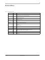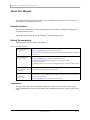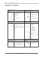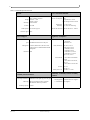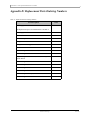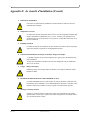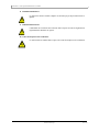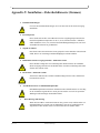
1
InfiniScale® IV 36-Port QSFP InfiniBand Switch User Manual P/N: MTS3600Q-1BNC, MTS3600Q-2BNC, MTS3600Q-1UNC, MTS3600Q-2UNC, MTS3600R-1BNC, MTS3600R-2BNC, MTS3600R-1UNC, MTS3600R-2UNC Rev 2.0.0 Mellanox Technologies 2 Copyright 2009. Mellanox Technologies. All rights reserved. Preliminary information. Subject to change without notice. Mellanox Technologies ConnectX, InfiniBlast, InfiniBridge, InfiniHost, InfiniRISC, InfiniScale, and InfiniPCI are registered trademarks of Mellanox Technologies, Ltd. Virtual Protocol Interconnect is a trademark of Mellanox Technologies, Ltd. All other trademarks are property of their respective owners. InfiniScale® IV 36-Port QSFP InfiniBand Switch User Manual Document Number: 2983 Mellanox Technologies, Inc. 350 Oakmead Parkway Sunnyvale, CA 94085 U.S.A. www.mellanox.com Tel: (408) 970-3400 Fax: (408) 970-3403 Mellanox Technologies Ltd PO Box 586 Hermon Building Yokneam 20692 Israel Tel: +972-4-909-7200 Fax: +972-4-959-3245 NOTE: THIS HARDWARE, SOFTWARE OR TEST SUITE PRODUCT (“PRODUCT(S)”) AND ITS RELATED DOCUMENTATION ARE PROVIDED BY MELLANOX TECHNOLOGIES “AS-IS” WITH ALL FAULTS OF ANY KIND AND SOLELY FOR THE PURPOSE OF AIDING THE CUSTOMER IN TESTING APPLICATIONS THAT USE THE PRODUCTS IN DESIGNATED SOLUTIONS. THE CUSTOMER'S MANUFACTURING TEST ENVIRONMENT HAS NOT MET THE STANDARDS SET BY MELLANOX TECHNOLOGIES TO FULLY QUALIFY THE PRODUCTO(S) AND/OR THE SYSTEM USING IT. THEREFORE, MELLANOX TECHNOLOGIES CANNOT AND DOES NOT GUARANTEE OR WARRANT THAT THE PRODUCTS WILL OPERATE WITH THE HIGHEST QUALITY. ANY EXPRESS OR IMPLIED WARRANTIES, INCLUDING, BUT NOT LIMITED TO, THE IMPLIED WARRANTIES OF MERCHANTABILITY, FITNESS FOR A PARTICULAR PURPOSE AND NONINFRINGEMENT ARE DISCLAIMED. IN NO EVENT SHALL MELLANOX BE LIABLE TO CUSTOMER OR ANY THIRD PARTIES FOR ANY DIRECT, INDIRECT, SPECIAL, EXEMPLARY, OR CONSEQUENTIAL DAMAGES OF ANY KIND (INCLUDING, BUT NOT LIMITED TO, PAYMENT FOR PROCUREMENT OF SUBSTITUTE GOODS OR SERVICES; LOSS OF USE, DATA, OR PROFITS; OR BUSINESS INTERRUPTION) HOWEVER CAUSED AND ON ANY THEORY OF LIABILITY, WHETHER IN CONTRACT, STRICT LIABILITY, OR TORT (INCLUDING NEGLIGENCE OR OTHERWISE) ARISING IN ANY WAY FROM THE USE OF THE PRODUCT(S) AND RELATED DOCUMENTATION EVEN IF ADVISED OF THE POSSIBILITY OF SUCH DAMAGE. Rev 2.0.0 Mellanox Technologies InfiniScale® IV 36-Port QSFP InfiniBand Switch User Manual 3 Table of Contents Table of Contents 3 Revision History 4 About this Manual 5 Intended Audience Related Documentation Conventions Switch Products Covered in this User’s Manual Mellanox Part Numbering Legend 5 5 5 6 6 Chapter 1 Overview 7 Chapter 2 1.1 Serial Number and Product Version Information 7 Installation and Basic Operation 8 2.1 Switch Platform Hardware Overview 2.1.1 Status LEDs 2.1.2 I2C Connector 2.1.3 Internal Management 2.1.4 Interfaces 2.2 Switch Platform Installation and Operation 2.2.1 Installation Safety Warnings 2.2.2 Mechanical Installation 2.2.3 Power Connections and Initial Power On 2.2.4 Extracting and Inserting the Power Supply Unit 2.2.5 InfiniBand Cable Installation 2.2.6 Extracting and Inserting the Fan Unit 2.2.7 Replacing the Battery in the Management Module 2.3 Disassembly of the Switch from the Rack 2.4 Disposal Chapter 3 Management and Tools Overview Chapter 4 8 8 10 10 11 11 11 13 16 17 18 19 20 20 21 22 3.1 Network Management and Clustering Software 3.2 Internally Managed Switch System 3.2.1 Initializing the switch for the first time 3.2.2 Accessing the Switch Locally 3.2.3 Starting a Remote Connection to the Switch 3.2.4 Downloading Firmware 22 22 23 23 23 23 Switch Management Tools 24 4.1 FabricIT 24 Chapter 5 Troubleshooting 25 Appendix A Specification 27 Appendix B Switch Hardware Components 31 Appendix C QSFP Interface 32 Appendix D Replacement Parts Ordering Numbers 33 Appendix E de sécurité d’installation (French) 34 Appendix F Installation - Sicherheitshinweise (German) 36 Appendix G Special Regulations Regarding Finland, Sweden, Denmark, and Norway 38 Mellanox Technologies Rev 2.0.0 4 Revision History Table 1 - Revision History Table Rev 2.0.0 Date Revision Description June 2009 Rev 2.0 Added Management module label and RS232 DB9 to DB9 harness Added part numbers for the two management modules. June 2009 Rev 1.9 Made fixes to management section added Disassembly instructions June 2009 Rev 1.8 Added Fabric IT section April 2009 Rev 1.7 inserted procedure to replace the battery. April 2009 Rev 1.6 Changes to installation kit and procedure January 2009 Rev 1.5 added installation instructions added ECM Removed Watermark November 2008 Rev 1.4 fixed weight in specs October 2008 Rev 1.3 Minor Formatting changes. September 2008 Rev 1.2 Added Reprogramming the MT3600 Through The I2C Port section. Added power cord OPNs to table 11 in Appendix D. September 2008 Rev 1.1 Fixed link to Software package page. September 2008 Rev 1.0 Initial release Mellanox Technologies InfiniScale® IV 36-Port QSFP InfiniBand Switch User Manual 5 About this Manual This manual describes the installation and basic use of the Mellanox MTS3600 switch, which is based on the InfiniScale IV InfiniBand switch device. Intended Audience This manual is intended for users and system administrators responsible for installing and setting up the switch platforms listed above. The manual assumes familiarity with the InfiniBand® Architecture Specification. Related Documentation Additional Documentation available from Mellanox: Table 2 - Reference Documents Switch Firmware and Firmware Update Tools See http://www.mellanox.com > Downloads > Firmware Tools. Note that the Switch System described in this manual is based on Mellanox Technologies’ InfiniScale® IV switch device. Mellanox OFED Stack for Linux User’s Manual See http://www.mellanox.com > Downloads > InfiniBand SW/Drivers, Click “Mellanox OpenFabrics Enterprise Distribution for Linux (MLNX_OFED)” Select the Linux User’s Manual The embedded OS and tools on the CPU in the management module is a subset of the Mellanox OFED stack. FabricIT Enterprise Fabric Management Software CLI User’s Manual Talk to your Mellanox representative for information regarding licensing and implementation of the FabricIT Enterprise Fabric Management Software System. Mellanox Firmware Tools (MFT) User’s Manual Document # 2329 The MFT (Mellanox Firmware Tools) package is a set of firmware tools. The manual supplied with this package provides an overview of the firmware its installation and replacement. The MFT can be downloaded with its documentation at: http://www.mellanox.com > Downloads > Firmware Tools. Conventions Throughout this manual, the name MTS3600 and the term switch are used to describe both the 36-port 40Gb/s InfiniBand Switch and the 36-port QSFP 20Gb/s InfiniBand Switch, unless explicitly indicated otherwise. Mellanox Technologies Rev 2.0.0 6 Switch Products Covered in this User’s Manual Table 3 - Switch Products Covered by this User Manual Product Number Description MTS3600Q-1BNC 36-port Managed QSFP 40Gb/s InfiniBand switch with one power supply MTS3600R-1BNC 36-port Managed QSFP 20Gb/s InfiniBand switch with one power supply MTS3600Q-1UNC 36-port Unmanaged QSFP 40Gb/s InfiniBand switch with one power supply MTS3600Q-2UNC 36-port Unmanaged QSFP 40Gb/s InfiniBand switch with two power supplies MTS3600R-1UNC 36-port Unmanaged QSFP 20Gb/s InfiniBand switch with one power supply MTS3600R-2UNC 36-port Unmanaged QSFP 20Gb/s InfiniBand switch with two power supplies Mellanox Part Numbering Legend Table 4 - Part Numbering Legend Place Rev 2.0.0 Field Decoder MT Mellanox Technologies S System Type S = Switch MM Model 36 = InfiniScale IV FF Form factor 00 = Rack mounted switch, 10 = Chassis C InfiniBand Port Config. G = CX4 DDR, J = CX4 QDR, Q = QSFP QDR, R = QSFP DDR, - Separator P # Power Supplies 0 = 0, 1 = 1, 2 = 2 M Management U = Unmanaged, A = Managed (Celeron), B = Managed (Freescale) Y Module Config. N = IB modules R RoHS C = RoHS w/ Exemption, R = RoHS Lead-Free Mellanox Technologies InfiniScale® IV 36-Port QSFP InfiniBand Switch User Manual 7 1 Overview Mellanox MTS3600 switch systems provide the highest performing fabric solution by delivering high bandwidth and low latency to Enterprise Data Centers, High-Performance Computing and Embedded environments. Networks built with MTS3600 systems can carry converged traffic with the combination of assured bandwidth and granular quality of service. Built with Mellanox’s 4th generation InfiniScale® IV InfiniBand switch device, MTS3600 systems provide up to 40Gb/s full bidirectional bandwidth per port. With 36 ports, these systems are among the densest switching systems available. These stand-alone switches are an ideal choice for top of-rack leaf connectivity or for building small to medium size clusters. The switch comes pre-installed with all necessary firmware and is configured for standard operation within an InfiniBand fabric. This switch requires an InfiniBand compliant Subnet Manager running from one of the hosts. All that is required for normal operation is to follow the usual precautions for installation and to connect the switch to the HCAs. Once connected, the Subnet Management software automatically configures and begins utilizing the switch. It is recommended that Mellanox OpenFabrics software package be installed on all nodes connected to the MTS3600. The software package provides a subnet manager and network management tools as well as connectivity software for servers and storage, and is available on the Mellanox web site. See Chapter 3 for more information. Basic installation, hot-swapping components and hardware maintenance is covered in “Installation and Basic Operation” on page 8. 1.1 Serial Number and Product Version Information The serial number and product version information are found on the label seen in the figure below. Figure 1: Generic Product label Also on this label is the GUID identifier for the switch. There is also a label with the MAC for the management module? Figure 2: Management Module Label Mellanox Technologies Rev 2.0.0 8 2 Installation and Basic Operation 2.1 Switch Platform Hardware Overview Figure 3 shows the power side panel and connector side panel views of the QSFP switch. The figure shows port configurations for the switch systems, including the dual hot-swap power supplies, and hot-swap fan module, I2C connector, RJ45 connector, USB connectors, VGA port connector, and various status LEDs. Figure 3: QSFP Switch System Front and Back Panels Front panel Rear panel All InfiniBand connectivity is via the connector side panel. All connectors can support active cables. 2.1.1 Status LEDs 2.1.1.1 System Status Indicators The System Status Indicators are located just to the left of the primary power supply unit, and labeled “Sys.”. The system status indicators should be as follows: When the switch is plugged in, within a few seconds the STATUS LED should light up green. The PSU 1 LED should light up green. The PSU 2 LED should light up green only if a second PSU is installed in the switch for redundancy and Hot-Swap ability. If only one PSU is installed in the switch, the PSU 2 LED will be off. The FAN LED should light up green. If the STATUS LED shows red unplug the switch and call your Mellanox representative for assistance. If the FAN LED shows yellow, trouble shoot the fan module. Note: Do not run the switch for more than 2 minutes should the FAN LED show yellow. If the PSU LEDs are not green, this indicates a problem with the power supplies. Do not run the switch if the PSU LEDs are not green. Rev 2.0.0 Mellanox Technologies InfiniScale® IV 36-Port QSFP InfiniBand Switch User Manual 9 Figure 4: Power and System LEDs Latch release mechanism Handle DC output from the PSU is OK System Status Indicators There is a fault in the PSU Switch Fan Status Indicators Input AC voltage is good PSU Status Indicators Table 5 - System Status LED/ Configurations LED Configuration Status OK – The system is up and running. Error –A fault in the system. Off – The system has no power. 2.1.1.2 Power Supply Status Indicators The MTS3600 36 Port Switch is available with one or two factory installed Power Supply Units. For switches with only one unit installed, a second Power Supply Unit can be added to increase security, hotswap ability and to add redundancy. Figure 5: MTS3600 QSFP Front Panel Place for secondary Power Supply Unit Fan Unit Mellanox Technologies Primary Power Supply Unit Rev 2.0.0 10 The primary power supply unit (PSU1) is located on the right side of the front panel, with PSU2 on the left side. Status indicators are located just to the left of where the primary power supply unit is located. Each PSU also has three status LEDs on the right side of the PSU, that indicate the internal status of the unit. ~AC– This LED when lit indicates input voltage between 90 and 264 Volts. –This LED when lit indicates a fault in the power supply. OK – This LED when lit indicates that the output from the power supply is +12VDC. The PSU status indicators are located just to the left of the primary power supply unit, and labeled “PSU1” and “PSU2”. The following status conditions are possible: 2.1.1.3 Fan Status Indicators The indicator labeled “Fans” is located just to the left of the primary power supply unit, next to PSU 1. The following fan status conditions are possible: Table 6 - Fan Status LED Configurations LED Configuration Status OK – All fans are operating. Error – One or more fans is not operating. Repair or replace the fan unit. Off – The fan unit is not receiving any power. Check that the fan unit is properly and completely inserted. All fans must be operating while the power supply is plugged in. Power must be removed within one minute of the fans failing, to prevent damage to the switch. 2.1.2 I2C Connector The MTS3600 supports an I2C compatible interface on the front panel.This interface is used to program firmware into the Flash Memory. Firmware can also be programmed in-band over the InfiniBand network. See Section 3 for more details. 2.1.3 Internal Management Internal management refers to a switch that has an internal PPC management board. Switches without this management board can be managed using an external management system. The following interfaces allow access to the internal management module. These interfaces have no function in externally managed systems. Rev 2.0.0 Mellanox Technologies InfiniScale® IV 36-Port QSFP InfiniBand Switch User Manual 11 2.1.4 Interfaces There are five interfaces to connect to the MTS3600. They are: 1 I2C DB9 interface is labelled “I2C”. This interface can be used to access and modify the Flash and EEPROM. 1 RS232 connector is labelled 2 USB ports is labelled 1 video connector is labelled . Use this connector to connect to the host PC. . Use these to connect to a local keyboard and mouse. . Use this to connect to a local video monitor. Figure 6: Management Interfaces 2.1.4.1 VGA Interface The VGA port is for video output from the management module. 2.1.4.2 RS232 Interface The RS232 connector interface is to be used to connect through the Ethernet to a remote host PC. 2.1.4.3 USB interface There are two USB ports for connecting a keyboard and mouse for local management operation. 2.2 Switch Platform Installation and Operation Installation and initialization of the switch platform are straightforward processes, requiring attention to the normal mechanical, power, and thermal precautions for rack-mounted equipment. The switch platform does not require any programming or configuration to operate as a basic InfiniBand switch and includes all of the necessary functionality to operate with external standard InfiniBand Subnet Management software. An Internal Management option is available for the switch platform which includes InfiniBand Subnet Management software embedded internally in the switch. This section describes the installation process and basic operation of the switch platform. Please first read the warnings sub-section carefully before carrying on with installation procedures. 2.2.1 Installation Safety Warnings For Safety Warnings in French see Section E,“de sécurité d’installation (French),” on page 34, and for German see Section F,“Installation - Sicherheitshinweise (German),” on page 36. Mellanox Technologies Rev 2.0.0 12 For Special Regulations Regarding Finland, Sweden, Denmark, and Norway see Section G,“Special Regulations Regarding Finland, Sweden, Denmark, and Norway,” on page 38. 1. Installation Instructions Read all installation instructions before connecting the equipment to the power source. 2. Over-temperature This equipment should not be operated in an area with an ambient temperature exceeding the maximum recommended: 45°C (113°F). Moreover, to guarantee proper air flow, allow at least 8cm (3 inches) of clearance around the ventilation openings. 3. Stacking the Chassis The chassis should not be stacked on any other equipment. If the chassis falls, it can cause bodily injury and equipment damage. 4. Redundant Power Supply Connection - Electrical Hazard This product includes a blank cover over the space for the redundant power supply. Do not operate the product if the blank cover is not securely fastened or if it is removed. 5. During Lightning - Electrical Hazard During periods of lightning activity, do not work on the equipment or connect or disconnect cables. 6. Copper InfiniBand Cable Connecting/Disconnecting Copper InfiniBand cables are heavy and not flexible, as such they should be carefully attached to or detached from the connectors. Refer to the cable manufacturer for special warnings and instructions. 7. Rack Mounting and Servicing When this product is mounted or serviced in a rack, special precautions must be taken to ensure that the system remains stable. In general you should fill the rack with equipment starting from the bottom to the top. 8. Equipment Installation This equipment should be installed, replaced, or serviced only by trained and qualified personnel. Rev 2.0.0 Mellanox Technologies InfiniScale® IV 36-Port QSFP InfiniBand Switch User Manual 13 9. Equipment Disposal Disposal of this equipment should be in accordance to all national laws and regulations. 10. Local and National Electrical Codes This equipment should be installed in compliance with local and national electrical codes. 11. Battery Replacement There is a risk of explosion should the battery be replaced with a battery of an incorrect type. Dispose of used batteries according to the instructions. 2.2.2 Mechanical Installation The switch platform can be rack mounted and is designed for installation in a standard 19” rack. The power side of the switch includes a hot-swap power supply module, a blank cover for an optional second PSU for redundancy, a hot-swap fan tray, system LEDs, and management connection ports. The hot-swap fan module provides front to back air flow. The rear of the switch has the QSFP ports. The switch platform contains auto-sensing 90 - 264 VAC connections for all possible PSUs. The installer should use a rack capable of supporting the mechanical and environmental characteristics of a fully populated platform. The rack mounting holes conform to the EIA-310 standard for 19-inch racks. Take precautions to guarantee proper ventilation for air intake at the power side of the chassis and exhaust at the connector side in order to maintain good airflow at ambient temperature. Cable routing in particular should not impede the air exhaust from the chassis. 2.2.2.1 Installing the Switch in the Rack Tools needed: Phillips Screwdriver ESD Strap ESD mat Mellanox Technologies Rev 2.0.0 14 Parts included in the installation kit: • 2 rails • 2 rail slides • 8 pan head screws M6 • 8 recessed flat head screws • 4 caged nuts • 2 metal washers Figure 7: Rack Installation Kit Parts rail rail slide Before you install your new MTS3600 switch, unpack the system and check to make sure that all the parts have been sent, check this against the parts list. Check the parts for visible damages that may have occurred during shipping. Note: If anything is damaged or missing, contact your customer representative immediately. Procedure 1. Place the ESD mat on the floor where you will be working and put on the ESD strap. Make sure the ESD strap is touching your skin and that the other end is connected to a verified ground. 2. Choose which side of the switch you want even with the vertical rack support. Either the side with the power supply units or the side with the IB connectors can be even with the vertical rack support. The other side of the switch will be further inside of the rack. Things to consider before choosing where to mount the rails and rail slides. Rev 2.0.0 Mellanox Technologies InfiniScale® IV 36-Port QSFP InfiniBand Switch User Manual 15 Figure 8: Which Side of the Rack Do You Want the Connectors? The distance between the rack and the door can be as little as 4 cm on one side of the rack and as much as 18 cm on the other side of the rack. Keep in mind that there can be as many as 36 cables connected to the switch. Do you want the connector side recessed in the rack to allow for larger cable bending radius? Will the connector side be recessed past other equipment in the rack and will this be problematic? 3. Install the rail slides onto the switch. Place the end of the rail slide with the 90o angle on the side of the switch that you want to be even with the vertical support of the 19” rack. Use four of the flat head screws for each rail slide. There are two sets of holes in the rail slide. Select the set of holes to either mount the switch closer or farther away from the rack vertical support. Tighten the screws to 3Nm or 26.5 pound inches. Figure 9: Screwing the Rail Slide onto the switch This side of the switch will be next to the vertical rack support. Mellanox Technologies Rev 2.0.0 16 4. Clip the nuts into the holes in the rack you will be using to connect the rail slides. Check that both sides of the switch are in the same position number on the rack. The caged nuts are separated by a single space 5. Using two of the pan head screws and one washer, for each rail, install the rails to the other end of the rack. Place the rail behind the holes in the rack and screw the screws through the holes in the washer then through the rails. Tighten the pan head screws that hold the rails to 9.2 Nm or 81.5 pound inches. Figure 10: Screwing in the Rails 6. Place the four bolts for the caged nuts within reach. 7. Slide the switch into the rails. 8. Put the switch into place and screw the bolts into the nuts from step 4. Tighten the bolts to 9.2 Nm or 81.5 pound inches. 9. Tighten all of the screws. 10. Plug in the power cables. 11. Check the Status LEDs and confirm that all of the LEDs show status lights consistent with normal operation. Warning: Any yellow status LEDs is cause for concern and must be dealt with immediately. 12. You can start connecting all of the cables to the switch. 2.2.3 Power Connections and Initial Power On The switch platform ships with one or two Power Supply Units. For switches with only one unit installed, a second PSU may be installed at a later time. Each supply has a separate AC receptacle. The input voltage is Rev 2.0.0 Mellanox Technologies InfiniScale® IV 36-Port QSFP InfiniBand Switch User Manual 17 auto-adjusting for 90-264 VAC, 47-63Hz power connections. The power cords should be standard 3-wire AC power cords including a safety ground and rated for 15A or higher. Caution: The switch platform will automatically power on when AC power is applied. There is no power switch. Check all boards, power supplies, and fan tray modules for proper insertion before plugging in a power cable. Caution: After inserting a power cable and confirming the green system status LED light is on; make sure that the Fan Status indicator shows green. If the fan status indicator is not green then unplug the power connection and check that the fan module is inserted properly and that the mating connector of the fan unit is free of any dirt and/or obstacles. Caution: When turning off the switch, make sure ALL LEDS are off to ensure a powered down status. Note: Do not hot swap the power supply if your switch has only one power supply. You must power down the system to replace the power supply unit when there is only one PSU in the switch. Figure 11: Two Power Inlets - Electric Caution Notifications CAUTION Risk of electric shock and energy hazard. The two PSUs are independent. Disconnect all power supplies to ensure a powered down state inside of the switch platform. ACHTUNG Gafahr des elektrischen Schocks. Entferrnen des Netzsteckers elnes Netzteils spannungsfrei. Um alle Einhieten spannungsfrei zu machen sind die Netzstecker aller Netzteile zu entfernen ATTENTION Risque de choc et de danger e’lectriques. Le de’branchment d’une seule alimentation stabilise’e ne de’branch uniquement qu’un module “Alimentation Stabilise’e”. Pour isoler completement le module en cause, Il faut de’brancher toutes les alimentations stabilise’es. 2.2.4 Extracting and Inserting the Power Supply Unit With both power supplies installed in the redundant configuration, either PSU may be extracted without bringing down the system. Note: Make sure that the PSU that you are NOT replacing is showing all green, for both the PSU and status indicators. Mellanox Technologies Rev 2.0.0 18 Figure 12: Power Supply Unit Extraction To extract a PSU: 1. Remove the power cord from the power supply unit. 2. Grasping the handle with your right hand, push the latch release with your thumb while pulling the handle outward. As the PSU unseats, the PSU status indicators will turn off. 3. Remove the PSU. To insert a PSU: 1. Make sure the mating connector of the new unit is free of any dirt and/or obstacles. 2. Insert the PSU by sliding it into the opening until a slight resistance is felt. 3. Continue pressing the PSU until it seats completely. The latch will snap into place confirming the proper installation. 4. Insert the power cord into the supply connector. Note: The green PSU indicator should light and the yellow indicator should remain off. If not, extract the PSU and re-insert it. 2.2.5 InfiniBand Cable Installation All cables can be inserted or removed with the unit powered on. To insert a cable, press the connector into the port receptacle until the connector is firmly seated. The GREEN LED indicator, corresponding to each QSFP port, will light when the physical connection is established (that is, when the unit is powered on and a cable is plugged into the port with the other end of the connector plugged into a functioning port). After plugging in a cable, lock the connector using the latching mechanism particular to the cable vendor. When a logical connection is made the yellow light will come on. When data is being transferred the yellow light will blink. Rev 2.0.0 Mellanox Technologies InfiniScale® IV 36-Port QSFP InfiniBand Switch User Manual 19 Note: Cables in the bottom row should be inserted up side down in relation to the how the cables are inserted in the top row. To remove, disengage the locks and slowly pull the connector away from the port receptacle. Both LED indicators will turn off when the cable is unseated. Care should be taken not to impede the air exhaust flow through the ventilation holes next to the InfiniBand ports. Cable lengths should be used which allow for routing horizontally around to the side of the chassis before bending upward or downward in the rack. Figure 13: Cable connections to the Switch 2.2.6 Extracting and Inserting the Fan Unit This switch can operate indefinitely with one of the three fans in the fan module inoperable so long as the ambient temperature is below 45° Celsius. Operation without a fan unit should not exceed one minute. During fan hot-swap, if both indicators are OFF then the fan unit is disconnected. To extract a Fan Unit: 1. Loosen the two thumb screws locking the fan tray in place. One of the fan status indicators (either green or yellow) will remain on. 2. Pull the fan unit out by pulling on the thumbscrews. As the fan unseats, the fan status indicator will turn off. To insert a FAN Unit: 1. Make sure the mating connector of the new unit is free of any dirt and/or obstacles. Mellanox Technologies Rev 2.0.0 20 2. Insert the fan unit by sliding it into the opening until slight resistance is felt. Continue pressing the fan unit until it seats completely. 3. Turn the two thumb screws to lock the fan unit in place. Note: The green fan status indicator should light and the yellow fan status should remain off. If not, extract the fan unit and reinsert it. After two unsuccessful attempts to install the fan unit, power off the switch before attempting any system debug. 2.2.7 Replacing the Battery in the Management Module The battery is only used for the clock within the management module. If the Battery is dead the time on the management module will not be updated. The battery is a lithium 3V CR2032. To replace the battery by: 1. Unplug all of the power chords and connectors from the switch. 2. Remove the switch from the rack. 3. Put on an ESD strap and ground the strap to a valid ground. 4. Remove the rail slides from the switch. Put aside the rail slides and screws for later use. 5. Remove the cover from the switch and put the cover and screws aside for later use. 6. Remove the battery from the holder. It is found near the front of the switch next to PSU1. 7. Insert the new battery + side up. 8. Replace the top cover using the screws set aside in step 5. 9. Reinstall the rail slides using the screws set aside in step 4. 10. Reinstall the switch in the rack. 11. Plug in the power cords and connectors. 2.3 Disassembly of the Switch from the Rack To disassemble the switch from the rack: 1. Unplug and remove all connectors. 2. Unplug all power cords. 3. Unscrew the 4 bolts from the side of the switch with the rail slides. See Figure 7,“Rack Installation Kit Parts” for a picture of the rail slides. Note: Support the weight of the switch when you remove the screws so that the switch does not fall. Rev 2.0.0 4. Slide the switch from the rack. 5. Remove the rails from the rack. Mellanox Technologies InfiniScale® IV 36-Port QSFP InfiniBand Switch User Manual 21 6. Remove the eight caged nuts. 2.4 Disposal According to the WEEE Directive 2002/96/EC, all waste electrical and electronic equipment (EEE) should be collected separately and not disposed of with regular household waste. Dispose of this product and all of its parts in a responsible and environmentally friendly way. Mellanox Technologies Rev 2.0.0 22 3 Management and Tools Overview 3.1 Network Management and Clustering Software Download and install on all nodes the Mellanox OpenFabric software package for Linux, Windows, or other operating systems from the Mellanox software website: http://www.mellanox.com.> Downloads > InfiniBand SW/Drivers. This software package provides connectivity for server and storage systems utilizing High Performance Computing (HPC) or enterprise data center (EDC) applications across an InfiniBand fabric. It also provides a subnet manager for simple network configuration and network administration and diagnostic tools for network management. 3.2 Internally Managed Switch System The switch system comes with a PPC controlled management module. The management module for this switch system runs SW that can manage the chassis. An option to upgrade the management module to be able to manage the whole fabric is available. See your Mellanox representative for information and pricing regarding this upgrade. The managed Switch system includes a CPU which contains: Embedded OS, secure In-band, out-band access Chassis manager & System BIST SNMP Agent, 3rd Party tool integration CLI and GUI Subnet manager Performance/provisioning manager Congestion & notification manager QoS manager Adaptive routing manager Cluster diagnostics manager Management modules with a CPU will have the capability to allow remote monitoring and remote management of the chassis from any host connected to the fabric. The Subnet management features include: Rev 2.0.0 upgrading Drivers upgrading software monitoring of: • AC power to the PSUs • DC power out from the PSUs • board temperature • spine fan module unit • leaf fan module unit Mellanox Technologies InfiniScale® IV 36-Port QSFP InfiniBand Switch User Manual 23 • failure in the switch system • system failure in the switch system querying for board serial numbers and their revisions In addition, the tools enable firmware management capabilities such as: querying for existing firmware versions burning new firmware (from scratch or for recovery from damaged firmware) querying for and changing system GUIDs checking for duplicate or bad GUIDs 3.2.1 Initializing the switch for the first time See FabricIT EFM user manual Section 3.1. 3.2.2 Accessing the Switch Locally For local access out of band management of the switch system use one of the two procedures below. 3.2.2.1 Accessing the CPU via a host PC Hook up a cable from the RS232 connector is labelled an RJ45 connector on the host PC side. to a host PC either using a USB connector or 3.2.2.2 Accessing the CPU via Keyboard, Video, Mouse (KVM) 1. Connect a keyboard to the one of the USB ports, a video device to the video connector, and a mouse to the second USB connector of the switch (cables not supplied). 2. Login using the following user name and password. User Name: admin Password: password Note: User name and password are case sensitive. 3. Change the default user name and password. 3.2.3 Starting a Remote Connection to the Switch See FabricIT EFM user manual Section 4. 3.2.3.1 Accessing the CPU via the Ethernet Connector Once the initial configuration is completed the management tools can be accessed through: SSH Telnet the WEB 3.2.4 Downloading Firmware Firmware for this switch system can be found at and downloaded from: http://www.mellanox.com > Downloads > Firmware. Be sure to read and follow all of the instructions regarding the updating of the firmware on your switch system. Firmware for the HCA cards connected to this switch system can be downloaded from the same site. Mellanox Technologies Rev 2.0.0 24 4 Switch Management Tools This chapter describes the management module tools. This management module allows the switch to be managed either locally or remotely. The switch can also be managed using Out-of-Band management of the switch via FabricIT EFM. The standard switch comes with a management module that will completely manage your switch. An optional management module is available that is more robust and can manage a whole fabric. 4.1 FabricIT FabricIT EFM is a software based management system that can be run with either a command line interface or with a GUI interface. The GUI interface can be run through the Web. A license is required for full use of FabricIT. The standard management module, without a license, allows for managing the switch using only a small subset of the commands available within FabricIT EFM. Make sure to register your FabricIT license to enable all of the available commands and functions. See the FabricIT EFM User Manual for instructions and commands available to manage the switches, and fabric. Rev 2.0.0 Mellanox Technologies InfiniScale® IV 36-Port QSFP InfiniBand Switch User Manual 25 5 Troubleshooting As soon as a switch is plugged in make sure that the green power LEDs on the PSUs are on. Status LED and or Status Health LED If either of these two LEDs is red unplug the switch and call your Mellanox representative. Power supply unit: 1. If the ~AC power LED is off, check that the power cable is plugged into a working outlet. Check that the power cable has a voltage within the range of 90 - 264 volts AC. 2. If the LED on the PSU is not lit or is red. 3. Remove and reinstall the power cable. 4. If the ~AC power LED is green but the OK power LED is off or the the PSU. LED is on – Replace The Status green power LED for PSU1 or PSU2 does not come on: 1. If the OK LED on the PSU is on but the system LED is off remove and reinstall the PSU. Make sure the mating connector of the new unit is free of any dirt and/or obstacles. 2. If the OK LED on the PSU is off, check that OK LED on the PSU Unit is on. 3. Remove and reinstall the power cable. Check that the power outlet (in the wall) is working. 4. Remove and reinstall the PSU. Make sure the mating connector of the new unit is free of any dirt and/or obstacles. 5. Replace the PSU. The power LED for the switch shuts off: 1. Check that the there is adequate ventilation. 2. Make sure that there is nothing blocking the front or rear of the chassis and that the fan modules and ventilation holes are not blocked (especially dust over the holes). 3. If you find dust blocking the holes it is recommended to clean the fan unit and remove the dust from the front and rear panels of the switch using a vacuum cleaner. The green power LED for the fans does not come on: 1. Check that the Power LEDs are on. 2. Remove and reinstall the fan unit. Make sure the mating connector of the new unit is free of any dirt and/or obstacles. See Section 2.2.6, “Extracting and Inserting the Fan Unit,” on page 19. Caution: Do not run the switch if the System Status LED for the Fans is Yellow! The link LED for the InfiniBand connector does not come on: 1. Check that both ends of the cable are connected. 2. Check that the locks on the ends are secured. Mellanox Technologies Rev 2.0.0 26 3. Make sure that the latest FW version is installed on both the HCA and the switch. 4. If media adapters are used, check that the all connections are good, tight, and secure. The activity LED does not come on: Check that the Subnet Manager has been started. Rev 2.0.0 Mellanox Technologies InfiniScale® IV 36-Port QSFP InfiniBand Switch User Manual 27 Appendix A: Specification Table 7 - MTS3600Q Specification Data Physical Power and Environmental Size: 1.73” (1U) H x 17.5” W x23.8” D 44mm X 444mm X 605mm Weight: 22.045 lbs. 1 PSU 24.60 lbs. 2 PSUs Mounting: 19” Rack mount Input Voltage: 90 - 264 VAC 47-63Hz Power Consumption: 326W Dissipated Power: 200W Power through connector:126W Temperature: 10° to 45° Celsius Humidity: 10% - 90% non-condensing Air Flow: 70.5CFM SerDes Speeds: 10, 20, or 40,Gb/s per port Shock and Vibration: ETSI EN 300 019-2-2: 1999-09 Connector Types: QSFP Protocol Support Regulatory Compliance InfiniBand: Auto-Negotiation of (40Gb/s, 20Gb/s, 10Gb/s) QoS: 8 InfiniBand Virtual Lanes for all ports Management: Baseboard, Performance, and Device management Agents for full InfiniBand In-Band Management Data Rate: QDR Safety: US/Canada: cTUVus EU: IEC60950 International: CB EMC (Emissions): USA: FCC, Class A Canada: ICES, Class A EU: EN55022, Class A EU: EN55024, Class A EU: EN61000-3-2, Class A EU: EN61000-3-3, Class A Japan: VCCI, Class A Environmental: EU: IEC 60068-2-64: Random Vibration EU: IEC 60068-2-29: Shocks, Type I / II EU: IEC 60068-2-32: Fall Test Acoustic: ISO 7779 ETS 300 753 Sound power level: 70.5 dB(A) or 7.1 Bel Reliability, Availability and Serviceability Features Scalability and Performance Switching Performance: Simultaneous wire-speed any port to any port Addressing: 48K Unicast Addresses Max. per Subnet 16K Multicast Addresses per Subnet Hot-Swappable: Fan Module and Power Supplies 1+1 Redundant: Power Supplies Switching Capacity: 2.88Tb/s Mellanox Technologies Rev 2.0.0 28 Table 8 - MTS3600R Specification Data Physical Power and Environmental Size: 1.73” (1U) H x 17.5” W x23.8” D 44mm X 444mm X 605mm Weight: 22.045 lbs. 1 PSU 24.60 lbs. 2 PSUs Mounting: 19” Rack mount Input Voltage: 90 - 264 VAC 47-63Hz Power Consumption: 316W Dissipated Power: 190W Power through connector:126W Temperature: 10° to 45° Celsius Humidity: 10% - 90% non-condensing Air Flow: 70.5 CFM SerDes Speeds: 10 or 20 Gb/s per port Shock and Vibration: ETSI EN 300 019-2-2: 1999-09 Connector Types: QSFP Protocol Support Regulatory Compliance InfiniBand: Auto-Negotiation of (20Gb/s or 10Gb/s) QoS: 8 InfiniBand Virtual Lanes for all ports Management: Baseboard, Performance, and Device management Agents for full InfiniBand In-Band Management Data Rate: DDR Safety US/Canada: cTUVus EU: IEC60950 International: CB EMC (Emissions) USA: FCC, Class A Canada: ICES, Class A EU: EN55022, Class A EU: EN55024, Class A EU: EN61000-3-2, Class A EU: EN61000-3-3, Class A Japan: VCCI, Class A Environmental EU: IEC 60068-2-64: Random Vibration EU: IEC 60068-2-29: Shocks, Type I / II EU: IEC 60068-2-32: Fall Test Acoustic ISO 7779 ETS 300 753 Sound power level: 70.5 dB(A) or 7.1 Bel Reliability, Availability and Serviceability Features Scalability and Performance Switching Performance: Simultaneous wire-speed any port to any port Addressing: 48K Unicast Addresses Max. per Subnet 16K Multicast Addresses per Subnet Switching Capacity: 1.44Tb/s Rev 2.0.0 Mellanox Technologies Hot-Swappable: Fan Module and Power Supplies 1+1 Redundant: Power Supplies InfiniScale® IV 36-Port QSFP InfiniBand Switch User Manual 29 A.1 EMC Certification Statements Table 9 lists the approved certification status per switch in different regions of the world Table 9 - Switch Certification Status Switch P/N FCC Class (USA) EN ICES VCCI Class Class (Japan) (Europe) (Canada) MTS3600R-1UNC A A A A MTS3600Q-1UNC A A A A MTS3600R-1BNC A A A A MTS3600Q-1BNC A A A A cTUVus CB A.1.1 FCC Statements (USA) Class A Statements: § 15.21 Statement Warning! Changes or modifications to this equipment not expressly approved by the party responsible for compliance (Mellanox Technologies) could void the user's authority to operate the equipment. §15.105(a) Statement NOTE: This equipment has been tested and found to comply with the limits for a Class A digital device, pursuant to Part 15 of the FCC Rules. These limits are designed to provide reasonable protection against harmful interference when the equipment is operated in a commercial environment. This equipment generates, uses, and can radiate radio frequency energy and, if not installed and used in accordance with the instruction manual, may cause harmful interference to radio communications. Operation of this equipment in a residential area is likely to cause harmful interference in which case the user will be required to correct the interference at his own expense. Mellanox Technologies Rev 2.0.0 30 A.1.2 EN Statements (Europe) EN55022 Class A Statement: Warning This is a class A product. In a domestic environment this product may cause radio interference in which case the user may be required to take adequate measures. A.1.3 ICES Statements (Canada) Class A Statement: “This Class A digital apparatus complies with Canadian ICES-003. Cet appareil numérique de la classe A est conforme à la norme NMB-003 du Canada.” A.1.4 VCCI Statements (Japan) Class A Statement: 0.0.1 (Translation - "This is a Class A product based on the standard of the Voluntary Control Council for Interference by Information Technology Equipment (VCCI). If this equipment is used in a domestic environment, radio interference may occur, in which case the user may be required to take corrective actions.") Rev 2.0.0 Mellanox Technologies InfiniScale® IV 36-Port QSFP InfiniBand Switch User Manual 31 Appendix B: Switch Hardware Components Primary Power Supply Unit Fan Unit Mellanox Technologies Place for Optional Secondary Power Supply Unit Rev 2.0.0 32 Appendix C: QSFP Interface 20 21 22 23 24 25 26 27 28 29 30 31 32 GND Rx2n Rx1n 18 Rx2p Rx1p 17 GND GND 16 Rx4n Rx3n Rx4p Rx3p GND GND ModPrsL SDA IntL SCL VccTx Vcc Rx Vcc1 ResetL LPMode GND ModSelL GND 33 Tx3p Tx4p 34 Tx3n Tx4n GND 35 36 37 38 Rev 2.0.0 19 GND GND 15 Table 10 - InfiniBand QSFP Connector Pinout Connector Connector Pin Number Pin Name Signal Description 14 1 GND Ground 13 2 Tx2n Transmitter Inverted Data Input 12 3 Tx2p Transmitter Non-Inverted Data Input 11 4 GND Ground 10 5 Tx4n Transmitter Inverted Data Input 9 6 Tx4p Transmitter Non-Inverted Data Input 8 7 6 5 4 7 GND 8 ModSelL Module Select Ground 9 ResetL Module Reset 10 Vcc Rx +3.3 V Power supply receiver 11 SCL 2-wire serial interface clock SDA 2-wire serial interface data Tx1p Tx2p 3 12 Tx1n GND Tx2n 2 1 13 GND Ground 14 Rx3p Receiver Non-Inverted Data Output 15 Rx3n Receiver Inverted Data Output 16 GND Ground 17 Rx1p Receiver Non-Inverted Data Output 18 Rx1n Receiver Inverted Data Output 19 GND Ground 20 GND Ground GND 21 Rx2n Receiver Inverted Data Output 3 22 Rx2p Receiver Non-Inverted Data Output 3 23 GND Ground 24 Rx4n Receiver Inverted Data Output 3 25 Rx4p Receiver Non-Inverted Data Output 3 26 GND 27 ModPrsL 28 IntL 29 Vcc Tx 30 Vcc 1 31 LPMode 32 GND Ground 33 Tx3p Transmitter Non-Inverted Data Input 34 Tx3n Transmitter Inverted Data Input 35 GND Ground 36 Tx1p Transmitter Non-Inverted Data Input 37 Tx1n Transmitter Inverted Data Input 38 GND Ground Mellanox Technologies Ground Module Present Interrupt +3.3 V Power supply transmitter +3.3 V Power Supply Low Power Mode InfiniScale® IV 36-Port QSFP InfiniBand Switch User Manual 33 Appendix D: Replacement Parts Ordering Numbers Table 11 - Replacement Parts Ordering Numbers Part Description OPN Power Supply Unit PSU MTP000018 This Replacement part is for both the PSU 1 and PSU 2. Power supply blank MTM003600 Rack installation kit MTR003600 Fan Unit for QSFP MTF000960 Management module 405 PPC SA000102 Management module upgrade to 460 PPC SA000102 RS232 CABLE - DB9 TO DB9 HARNESS HAR000040 Power cord Type B for USA, Canada, Mexico, Taiwan ACC000204 Power cord Type H for Israel ACC000205 Power cord Type E/F for Sweden, France, Germany, Neth- ACC000207 erlands, Russia Power cord Type G for UK ACC000208 Power cord Type D for India ACC000209 Power cord Type I for China ACC000210 Power cord Type J for Switzerland ACC000211 Power cord Type B for Japan, ACC000212 Power cord Type I for Australia ACC000213 Mellanox Technologies Rev 2.0.0 34 Appendix E: de sécurité d’installation (French) 1. Instructions d’installation Lisez toutes les instructions d’installation avant de brancher le matériel à la source d’alimentation électrique. 2. Température excessive Ce matériel ne doit pas fonctionner dans une zone avec une température ambiante dépassant le maximum recommandé de 45°C (113°F). En outre, pour garantir un bon écoulement de l’air, laissez au moins 8 cm (3 pouces) d’espace libre autour des ouvertures de ventilation. 3. Empilage du châssis Le châssis ne doit pas être empilé sur un autre matériel. Si le châssis tombe, il peut provoquer des blessures corporelles et des dégradations de biens. 4. Connection d'Alimentation electrique excedentaire -dangers électriques Ce produit comporte un couvercle transparent sur l’espace pour l’alimentation électrique redondante. Ne pas faire fonctionner le produit si le couvercle transparent n’est pas solidement fixé ou s’il est enlevé. 5. Orages – dangers électriques Pendant un orage, il ne faut pas utiliser le matériel et il ne faut pas brancher ou débrancher les câbles. 6. Branchement/débranchement des câbles InfiniBand en cuivre Les câbles InfiniBand en cuivre sont lourds et ne sont pas flexibles, il faut donc faire très attention en les branchant et en les débranchant des connecteurs. Consultez le fabricant des câbles pour connaître les mises en garde et les instructions spéciales. 7. Montage et entretien sur baie Lorsque ce produit est monté ou entretenu sur baie, il faut prendre des précautions spéciales pour s’assurer que le système reste stable. En général, il faut remplir la baie avec du matériel de bas en haut. Rev 2.0.0 Mellanox Technologies InfiniScale® IV 36-Port QSFP InfiniBand Switch User Manual 35 8. Installation du matériel Ce matériel ne doit être installé, remplacé ou entretenu que par du personnel formé et qualifié. 9. Elimination du matériel L’élimination de ce matériel doit s’effectuer dans le respect de toutes les législations et réglementations nationales en vigueur. 10. Codes électriques locaux et nationaux Ce matériel doit être installé dans le respect des codes électriques locaux et nationaux. Mellanox Technologies Rev 2.0.0 36 Appendix F: Installation - Sicherheitshinweise (German) 1. Installationsanleitungen Lesen Sie alle Installationsanleitungen, bevor Sie das Gerät an die Stromversorgung anschließen. 2. Übertemperatur Dieses Gerät sollte nicht in einem Bereich mit einer Umgebungstemperatur über der maximal empfohlenen Temperatur von 45°C (113°F) betrieben werden. Außerdem sollten mindestens 8 cm (3 in.) Freiraum um die Belüftungsöffnungen sein, um einen einwandfreien Luftstrom zu gewährleisten. 3. Stapeln des Chassis Das Chassis sollte nicht auf andere Geräte gestapelt werden. Wenn das Chassis herunterfällt, kann es zu Verletzungen und Beschädigungen an Geräten führen. 4. Redundanter Stromversorgungsanschluss - Elektrische Gefahr Dieses Produkt verfügt über eine Abdeckung über dem Bereich für die redundante Stromversorgung. Betreiben Sie das Produkt nicht, wenn diese Abdeckung nicht sicher festsitzt oder entfernt wurde. 5. Bei Gewitter - Elektrische Gefahr Arbeiten Sie während eines Gewitters und Blitzschlag nicht am Gerät, schließen Sie keine Kabel an oder ab. 6. Anschließen/Trennen von InfiniBand-Kupferkabel InfiniBand-Kupferkabel sind schwer und nicht flexible. Deshalb müssen sie vorsichtig an die Anschlüsse angebracht bzw. davon getrennt werden. Lesen Sie die speziellen Warnungen und Anleitungen des Kabelherstellers. 7. Rack-Montage und Wartung Wenn dieses Produkt in einem Rack montiert oder gewartet wird, sind besondere Vorsichtsmaßnahmen zu ergreifen, um die Stabilität des Systems zu gewährleisten. Im Allgemeinen sollten Sie das Gestell von unten nach oben mit Geräten füllen. Rev 2.0.0 Mellanox Technologies InfiniScale® IV 36-Port QSFP InfiniBand Switch User Manual 37 8. Geräteinstallation Diese Gerät sollte nur von geschultem und qualifiziertem Personal installiert, ausgetauscht oder gewartet werden. 9. Geräteentsorgung Die Entsorgung dieses Geräts sollte unter Beachtung aller nationalen Gesetze Bestimmungen erfolgen. 10. Regionale und nationale elektrische Bestimmungen Dieses Gerät sollte unter Beachtung der regionalen und nationalen elektrischen Bestimmungen installiert werden. Mellanox Technologies Rev 2.0.0 38 Appendix G: Special Regulations Regarding Finland, Sweden, Denmark, and Norway Denmark- This unit is class I and must be connected with an AC cord compliant with all national electrical codes in Denmark. The AC cord shall have an integral ground wire, and can only be plugged into a fully grounded outlet. Do not connect this unit to any outlet that is not fully grounded! Finland “Laite on liitettävä suojamaadoituskoskettimilla varustettuun pistorasiaan” Norway “Apparatet må tilkoples jordet stikkontakt” Unit is intended for connection to IT power systems for Norway only. Sweden “Apparaten skall anslutas till jordat uttag.” Rev 2.0.0 Mellanox Technologies