1
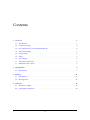
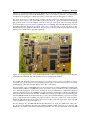
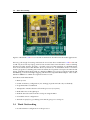
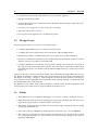
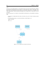
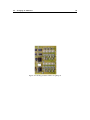
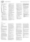
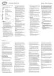
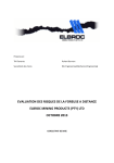
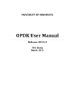
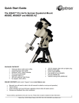
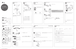
ColdFire Embedded System Ian Clark E-mail: [email protected] Original work documented January, 2003 Posted Feb 2011, low resolution images. http://www.secondvalleysoftware.com/hardware/coldfire/pdfs/coldfire.pdf Contents 1 Overview 1 1.1 Introduction . . . . . . . . . . . . . . . . . . . . . . . . . . . . . . . . . . . . . . . . . 1 1.2 Company Startup . . . . . . . . . . . . . . . . . . . . . . . . . . . . . . . . . . . . . . 3 1.3 Development Done on the BetaTech Boards . . . . . . . . . . . . . . . . . . . . . . . 4 1.4 Work Outstanding . . . . . . . . . . . . . . . . . . . . . . . . . . . . . . . . . . . . . 5 1.5 Design Issues . . . . . . . . . . . . . . . . . . . . . . . . . . . . . . . . . . . . . . . . 6 1.6 Status . . . . . . . . . . . . . . . . . . . . . . . . . . . . . . . . . . . . . . . . . . . . . 6 1.7 LCD Display . . . . . . . . . . . . . . . . . . . . . . . . . . . . . . . . . . . . . . . . . 7 1.8 Alternatives Platforms . . . . . . . . . . . . . . . . . . . . . . . . . . . . . . . . . . . 7 1.9 Industrial Partner Trials . . . . . . . . . . . . . . . . . . . . . . . . . . . . . . . . . . 7 2 Specifications 2.1 9 Introduction . . . . . . . . . . . . . . . . . . . . . . . . . . . . . . . . . . . . . . . . . 3 Booting 9 11 3.1 Introduction . . . . . . . . . . . . . . . . . . . . . . . . . . . . . . . . . . . . . . . . . 11 3.2 Booting Linux . . . . . . . . . . . . . . . . . . . . . . . . . . . . . . . . . . . . . . . . 11 4 Summary 13 4.1 The Move to MIPS . . . . . . . . . . . . . . . . . . . . . . . . . . . . . . . . . . . . . 13 4.2 Changing IP Addresses . . . . . . . . . . . . . . . . . . . . . . . . . . . . . . . . . . . 14 ii List of Figures 1.1 Underside of BetaTech V1.0 PIT ColdFire prototype board . . . . . . . . . . . . . 1 1.2 Component side of the BetaTech V1.0 PIT ColdFire prototype board . . . . . . . . 2 1.3 Second BetaTech ColdFire core board and base board . . . . . . . . . . . . . . . . . 3 1.4 Fly Swatter JTAG Interface . . . . . . . . . . . . . . . . . . . . . . . . . . . . . . . . . 4 1.5 BetaTech ColdFire core board on barcode base board . . . . . . . . . . . . . . . . 5 3.1 Development environment connections. . . . . . . . . . . . . . . . . . . . . . . . . . 12 4.1 Reading Setup Switches via QSPI port . . . . . . . . . . . . . . . . . . . . . . . . . . 14 4.2 Writing to Status LEDs via QSPI port . . . . . . . . . . . . . . . . . . . . . . . . . . . 15 iii List of Tables 2.1 BetaTech PIT Features . . . . . . . . . . . . . . . . . . . . . . . . . . . . . . . . . . . 2.2 BetaTech Core Module and Baseboard Features 2.3 BetaTech Core Module and Barcode Baseboard Features . . . . . . . . . . . . . . . . . . . . . . . . . . . . . . . . . . . 9 10 10 History Revision 1.1 1.2 Date 23rd Jan 2001 4th Feb 2003 22nd Nov 2006 21st Feb 2011 Description Original Edited update Added to Fire Alarm proposal, same “look and feel” Lower resolution photos for web posting Revision 1.2 of February 21, 2011 At the end of October, 2006, a company manufacturing fire alarms requested a ColdFire proposal. This document was updated with photographs and given a similar “look and feel” to my other documents or manuals. We moved away from the Python Manual class as the page numbering caused problems. For posting on our website, we converted the photographs from high resolution JPGs to lower resolution PNG files. The original was 22 Meg. This version was posted Feb, 2011, and was 3,511 kBytes (almost five times smaller). iv Chapter 1 Overview 1.1 Introduction Figure 1.1: Underside of the BetaTech V1.0 PIT ColdFire prototype board showing the power supply, connectors, P&E Micro debug port and socket for Flash (in case the soldered down Flash could not be programmed). The heat damage on the Flash socket was due to a heat gun on the opposite side of the BGA part, as the first time the board was reflowed, the profile had not been sorted out and pressing on the BGA part allowed the board to boot. This document gives the status of a ColdFire Embedded System that was to be used for connecting barcode readers to TCP/IP (Transmission Control Protocol/ Internet Protocol). The ColdFire work started after a visit to BetaTech in Johannesburg in April, 2002, to help with a 1 2 Chapter 1. Overview Linux port. The first system supplied by BetaTech was the TCP/IP PIT, version 1.0 of 9/2001, which was based on the Motorola MCF5272C ColdFire evaluation platform. The Linux port was done by Greg Ungerer of SnapGear (Lineo). The board is shown in Figures 1.1 and 1.2. The early work was to read the setup switches via the ColdFire’s QSPI (queued serial port interface), write values to the status LEDs connected to the Port A pins, read and write the Flash, plus general tasks to become familiar with the ColdFire Linux port. The following manuals were useful [Motorola(1995), Motorola(2001a), Motorola(2001b)]. The embedded Linux tools were upgraded when the kernel moved from a 2.2 to 2.4. A fair amount of work was done on the board with 25 hours funded by BetaTech. The goal was to develop industrial equipment that was Internet aware with remote upgrade capability. Figure 1.2: Component side of the V1.0 PIT BetaTech ColdFire prototype board showing the CPU and 32-bit SDRAM. The DIP switches were for setting the IP address. The V1.0 board allowed a quick evaluation, however, there were no user accessable I/O points, and with only one RS-232 port it was unsuitable for barcode work if the first serial port was used for debugging. (BetaTech uses RS-485 for their video controllers). Several months of prior embedded Linux work was based on an Ampro MIPS32 board (M2 with Alchemy Semiconductor Au1000 CPU), but it also had no user accessable I/O. See [Clark(2002)] for a detailed description of the work. During the work for BetaTech, I completed (schematic capture) a design based on an Au1000 device due to problems with Ampro’s M2 board (withdrew from the market to replace with the M3/ Au1500 CPU). During a periodic visit to Johannesburg in October 2002, BetaTech showed me their new ColdFire board which had several user accessable ports, a large baseboard for testing, I/O and a modular connector so end-users could customise the baseboard without having to respin a processor board for each new application. A photograph of the combination is shown in Figure 1.3. The two designs (my Au1000 and BetaTech’s MFC5273 Core V1.0 of 6/2002) were fairly similar, however, the BetaTech board used a different Ethernet PHY (Physical Layer Device) and included a reasonable sized FPGA (Field Programmable Gate Array). The PHY on the Au1000 1.2. Company Startup 3 Figure 1.3: Second BetaTech ColdFire evaluation board (red outline) seated on a large prototyping base board. The power leads taken from an external 5 V DC supply were due to obscure power problems that would be checked out later (baseboard was two sided to push a few limits). was the same as the Ampro M2 to reduce software porting effort, however, the Broadcom device would have to be imported with MOQ (Minimum Order Quantities) as there was no local agent. For the Au1000 design to get to where the new BetaTech board was, would take an additional three months minimum. To reduce the risk of development company start-up funds and to begin development immediately, the BetaTech route was chosen. Even though it was a different processor, at the C application level there would be minimal architecture differences assuming piping was not required. For deeply embedded applications, users are unlikely to see a shell interface anyway. 1.2 Company Startup I was given a BDM (Background Debug Mode) interface pod, CDs with the GNU (GNU is Not Unix) tools, the core board and a base board by BetaTech. Before returning to Port Elizabeth, I picked up a MetroWerks evaluation CD from the Pretoria agents. A photo of BetaTech’s JTAG (Joint Test Action Group) equivalent interface, the Fly Swatter is shown in Figure 1.4. The BetaTech board allowed immediate software development, however, not all the hardware was fully debugged. I would assist where possible, as part of a joint project. We would also swap VHDL (VHSIC High-level Definition Language) files for peripherals that were of mutual interest. The startup company costs went from close to R100K to R45K — three months at R15K to fund development. A closed corporation with three people in Port Elizabeth was formed to develop an industrial terminal with barcode to Ethernet capability. This was in the last quarter of 2002. An added advantage of going with the BetaTech board was that they were going to use the board themselves and there would be local support. They also have a factory with several million Rand’s worth of pick-and-place machines and reflow ovens. They would manufacture the boards and 4 Chapter 1. Overview Figure 1.4: P&E Micro compatible JTAG to parallel port interface. sort out component purchasing — significant advantages due to MOQ and assembling BGA (Ball grid array) and surface mount packages. 1.3 Development Done on the BetaTech Boards The cross-compiler [Lineo(2002)] and kernel were downloaded from the µC-Linux website (www.uclinux.org), and installed on a x86 laptop running Linux. The toolchain was tested and the Linux kernel successfully downloaded to the ColdFire target. Efforts to get NFS (Network File System) running failed. After printing out the NFS related software (well over 100 pages), I decided to wait for the next kernel release before attempting anything further on NFS. (Most of the NFS work was at least a couple of years old, so it was odd that the ColdFire version did not work when going from the 2.2 to 2.4 kernel). The baseboard supplied with the second BetaTech board was too large for the intended housing for the barcode reader, so a smaller baseboard was designed and manufactured. A photo of the barcode reader base board can be seen in Figure 1.5. In November 2002, BetaTech said that the next board would use a larger FPGA with different pinouts to the baseboard. The visit was mainly to sort out downloading problems, as I thought something on the board had blown. This was a bit of a surprise as I had already developed a baseboard for the barcode application. While the board was out of action, VHDL code was written to access the LCD (Liquid Crystal Display) once the board was repaired/ replaced. The problem was related to a power supply, but BetaTech also experienced problems with downloading from their PCs. I took my laptop with to Johannesburg, and with a higher voltage power input, the board booted over Ethernet most times. The power supply problem was easily solved by directly connecting 5 V DC to the board from a PC power supply. (See Figure 1.3). The Ethernet problem was not completely solved, 1.4. Work Outstanding 5 Figure 1.5: BetaTech ColdFire core board on smaller base board for barcode reader applications. but was good enough for testing on the bench. It was later discovered that the ColdFire board would only boot from my laptop, and not from another faster Linux based PC. After examining the Motorola dBug monitor program, a possible cause was that interrupts are disabled during most of the TFTP (Trivial File Transfer Protocol) download. To instrument TFTP or rewrite a monitor program is a daunting task. In the meantime, development was kept to the Linux based laptop, with MetroWerks being used on a Windows 2000 PC for low-level code development and board debug, as it allowed single stepping with the P&E compatible BDM adapter. I also used a Windows 2000 PC for VHDL development for FPGA code. Work done under MetroWerks: • Memory tests • Sorted out memory configuration (4 to 16 Meg) (in pre-download code, not flashed) • Programmed the second Flash • Attempted to initialise the FPGA from the processor (not JTAG) • Read and write via the QSPI port • Read the barcode reader from the serial port using the FIFO • Cleared the FPGA configuration • Worked on sprintf() to get a debug environment going via a serial port. 1.4 Work Outstanding • Download FPGA configuration via the processor 6 Chapter 1. Overview • Communicate between the CPU and FPGA (access internal registers) • Test the LCD block in VHDL • Populate the baseboard for installation in the old Welch-Allyn housing to replace the obsolete barcode readers • Sort out a power supply for 3.3 V DC for the above housing • Test LCD code on the ColdFire • Develop a barcode application for an industrial partner 1.5 Design Issues The prototype board was to evaluate several design issues: • Could the QSPI address spaces overlap for read and write? • Could the FPGA be configured via slave serial mode, and SelectMap mode? • Would it be possible to combine all the JTAG ports (CPU, FPGA, Ethernet PHY)? • Platform for VHDL development for I2 C, UART (Universal Asynchronous Receiver Transmitter)s, LCD port, real-time clock and keypad. • Could the Ethernet work with the worst possible routing? The transformer is placed on the opposite side of the baseboard to test this. (Note the “Halo” transformer at the bottom left hand side of the core module and the Ethernet RJ45 at the top of the base board in Figure 1.3.) Answers to the above were found out by writing code and testing; The QSPI addresses can overlap. BetaTech claimed to combine all the JTAG ports, but there were problems as mentioned in the chapter on booting — Chapter 3. Alan managed to download a FPGA bit file from the processor, but the code he supplied did not explain the switch settings required, or whether the code was tested under Linux or MetroWerks. The Ethernet works under Linux without problems, and the TFTP download problems were related to Motorola’s dBug monitor program and the host TFTP server. 1.6 Status • The hardware was not completely debugged, or in a state to commit to testing in a factory. • Without reliable TFTP download capability, the target cannot be deployed, and only working from my laptop makes it awkward when I am not there. • The battery backed-up memory did not work and will require significant effort to design around (program Flash etc). • I do not have the test equipment to debug the FPGA (decent scope – at least 500MHz) • The long-term commitment to the board will not depend on our purchases, but on their new owners (Honeywell), who will certainly will not be willing to design for us with our quantities and budgets. 1.7. LCD Display 7 • The ColdFire is an excellent device, but long term commitment will require purchasing MetroWerks at $4000. (Freescale have since bundled free versions of Metrowerks and GNU tools with selected ColdFire boards). • The ColdFire Linux port is for a CPU without a MMU (Memory Management Unit) which does not support shell redirection or ‘piping’ • My other projects were MIPS based. Without funding, there will be diminishing returns in staying with the ColdFire device as there were no other immediate customers. • Staying with the ColdFire device will require a board redesign, however, we have a platform that mostly works, as well as access to circuit diagrams that are mostly tested. Motorola are particularly good at supplying application notes, code and evaluation boards. The “Fly Swatter” BDM debugger saved $2300 for the equivalent MIPS device, but this would be countered when purchasing MetroWerks. 1.7 LCD Display The ColdFire board requires a working FPGA to drive the LCD. An embedded PC interim solution would require a graphics LCD, as they are designed to use these for the VGA output. A serial port LCD could be done, but would also take about a month to develop, test and package. Prior work on a BrightStar Engineering PowerPC board had a FPGA with several user accessable ports that were used for testing a 4x20 LCD port. 1.8 Alternatives Platforms There are several alternatives: • Purchase Motorola ColdFire evaluation boards, but this is rather expensive for deployment. • Move to a PowerPC platform (IP Engine from BrightStar Engineering), but they do not supply monitor source code or library source code for Linux. They relied on a MontaVista download for the Linux based development tools, but this is no longer available. The development platform I have is Windows based. • Move to a MIPS platform, but this takes everything back to the start. Attempt embedded Linux on the M2 replacement board from Ampro (M3). • Install embedded PC with an LCD (graphics) to run the Linux software • Press on with the ColdFire processor 1.9 Industrial Partner Trials The obsolete communications multiplexor would be replaced by Ethernet based devices and the software changed. The intention was to have a telnet compatible device. The source code for telnet is approximately 180 pages which will need to be modified to take input from a barcode (rather than the Linux stdin) and send output to a small LCD with Linux curses compatible screen addressing. This is not going to happen until the hardware is fully debugged. An estimate cannot be given at this stage, as the code has not been fully studied. 8 Chapter 1. Overview An alternative is to use Sun Microsystems’ RPC (Remote Procedure Call) and have the application based on network sockets. This involves some software development from the partner’s side, or our side on their host. Unfortunately, both target and host development cannot proceed concurrently with both being critical deadlined projects. Several problems appeared fairly late in the development cycle. These were mainly related to hardware, which was to be expected when working on a prototype. Development problems are normally sorted out as they are discovered, however, this depends on the time available to the original developer. In any new development, if the client is expecting a 100% debugged product before field trials, then there are bound to be tears. Timing estimates for the introduction, field trials, packaging etc. will be done after an industrial terminal is sufficiently debugged. A description of which way the development went is given in Chapter 4. Chapter 2 Specifications 2.1 Introduction Three boards are presented: the stand-alone BetaTech PIT, the BetaTech Core module combined with their baseboard, and the BetaTech Core module combined with a smaller baseboard designed by myself. The boards all aim at developing an Internet aware unit which will allow remote upgrades, reasonable cost, reasonable processing power, and rapid software development. Table 2.1: BetaTech PIT Features Features Description Processor Memory Size Connections Debug Power Status LEDs Setup switches Other Motorola Coldfire MCF5273 1 x 2 Mbyte Flash, 4 Mbyte SDRAM 145 x 125mm Small self-contained board RS-232-C, RS-485, 10/100Mb/s Ethernet P&E compatible BDM board 12 V DC or 12→ 17 VAC 4 on Port A 4 x 8 on QSPI (queued serial peripheral interface) Switcher for 3.3 V DC and linear for 2.5 V DC 32-pin DIP (Dual In-line Package) socket for Flash Same Flash as Motorola Evaluation board, allows dBug updates 9 10 Chapter 2. Specifications Table 2.2: BetaTech Core Module and Baseboard Features Features Description Processor Memory Size Connections Motorola Coldfire MCF5273 2 x 4 Mbyte Flash, 16 Mbyte SDRAM, 512Kx16 battery backed SRAM 105 x 105mm module to plug into baseboard RS-232-C, RS-485, 10/100Mb/s Ethernet from CPU RS-232, RS-485, I2 C, LCD from FPGA P&E compatible BDM board 12 V DC or 12→ 17 VAC 2 from Port A, 3 from Port B, 8 from a ’574 latch, and 32 from QSPI 4 x 8 on QSPI Switcher for 3.3 V DC and linear for 2.5 V DC 30K gate FPGA Two Flash devices allows remote update without over-writing boot Flash Debug Power Status LEDs Setup switches Other Table 2.3: BetaTech Core Module and Barcode Baseboard Features Features Description Processor Memory Size Connections Motorola Coldfire MCF5273 2 x 4 Mbyte Flash, 16 Mbyte SDRAM, 512Kx16 battery backed SRAM 105 x 105mm module to plug into baseboard 2 x RS-232-C, 10/100Mb/s Ethernet from CPU 3 x RS-485, LCD from FPGA P&E compatible BDM board 5 V DC or 3.3 V DC 2 from Port A, 3 from Port B, 8 from ’574 latch Requires external 3.3 V DC. Module has 2.5 V DC regulator for CPU 30K gate FPGA Two Flash devices allows remote update without over-writing boot Flash Debug Power Status LEDs Other Chapter 3 Booting 3.1 Introduction There are various quirks to booting, particularly when the hardware is still being debugged. This chapter was a place holder to describe how to connect to the board so that any tests could be repeated without having to take up archeology. Also the original developers had moved overseas, so the records or folklore would be lost forever. 3.2 Booting Linux On power-up without the BDM cable connected, the Motorola debug monitor, dBug boots the board, which was setup to download the Linux kernel, image0, via TFTP. The host was setup, and after running make clean, make dep, and make, the image0 file is copied into the host’s /tftpboot directory. The target was setup as address 192.168.0.41 and the host as 192.168.0.40. These addresses were fixed in the version of dBug that was compiled and loaded by Betatech. The normal dBug variable settings cannot be changed, as the target has a different Flash, which cannot be updated by the monitor program. The downloaded program, CFlasher only works with the original Motorola Evaluation board’s Flash. There is a commercial package from P&E Micro for R2000 to program various Flash devices from the BDM port. At this stage I was happy with the fixed addresses. After the board powers up into dBug, the FPGA software was downloaded via the Xilinx JTAG cable. The monitor program no longer runs after this, and the board must be reset. Once the Linux kernel had booted, the FPGA download was attempted via the Xilinx JTAG cable, but the Xilinx software reports a cable failure. When using the MetroWerks software and the BDM port, there is a switch that needs to be ‘off’ for the BDM, and ‘on’ for the FPGA JTAG download. The FPGA has several problems due to connections and pullup resistors missing/ configuration software requirements for pullups. These will take some time to debug. It is not known whether the processor is able to read/ write FPGA registers, as there are only three status LEDs connected to the FPGA that can be written to, and so far unsuccessfully. This could be faulty VHDL code, address setup problems, chip select software errors in CPU initialisation etc. An oscilloscope is required to sort this out (500MHz). MetroWerks cannot single-step once the Xilinx FPGA has used the JTAG, and the BDM switch was changed. The errors are “unable to initialise the target registers”, not being able to write to SDRAM location 0x0000 etc. The target board’s power must be cycled to be able to download 11 12 Chapter 3. Booting again. One way to use the MetroWerks is to download the target, run without any breakpoints, and then download the Xilinx bitstream from another PC via the Xilinx JTAG cable. A test with a logic probe shows some chip select activity at the FPGA, but this would need to be mapped to one of the output LEDs so that the internal decoding can be viewed with an oscilloscope for access violations. The following steps were written in to the printed document that was last updated 4th February, 2003: • Download via MetroWerks first (SW1 off). Must cycle power if Xilinx already used the JTAG. • Download Xilinx (SW1 on). Once downloaded, can switch SW1 to off. dBug commands dn go 200000 Figure 3.1: Development environment connections. Chapter 4 Summary This chapter was written fairly late in 2003, as it references the next design in [Clark(2003)]. Several years have past and still we have no industrial terminal or barcode reader. So what happened? Unfortunately for us, Alan and Peter relocated to the United Kingdom following BetaTech’s acquisition by Honeywell (Video Controls Limited in UK). They obviously had to continue “business as usual” during their negotiations, but we were unaware that there would move overseas. We were told shortly before that the amounts would mean they would not have to work again, however, we were several months down the road with the ColdFire work. Had we been in a similar position, we would have done the same. Their generosity in time and equipment was much appreciated and if we were better funded, we could have pressed on. We would have to revert to a platform that we were more comfortable with — MIPS. 4.1 The Move to MIPS Ampro admitted to some errors with their M2 evaluation board. They also withdrew it from the market and replaced the M2 with an M3 board. The M3 was based on an Au1500 rather than the previous Au1000 in the M2. The Linux port was no longer from MontaVista, but from TimeSys. I completed the development on the M3 and made a small LCD interface that ran off the serial port (used an AVR board from the warehousing project). This was later changed to a board developed by an outside contractor in an effort to get a packaged unit while I was busy working on the MIPS code. The M3 was placed in the computer section at a tyre plant with a Linux based PC. The development was moved to a HP-UX box and later to a Sun SPARC box. The interface to the database was tested and everything worked except being able to easily change IP addresses. The M3 was fairly expensive to deploy (R17 000 per kit). A company in Stellenbosch was busy developing their own Au1000 board and sent two of their developers to work with me for a week to port Linux to their board and get the tool chain running on a Linux PC. This was really useful as they also promised to supply Au1000 boards for R5000. Eventually the locally developed Au1000 board was running at the tyre plant. Two things happened close together to sink the project — a lightning strike took out the Sun hard drive and the plant had to run off Cape Town (remote bureau). This also took out the Au1000 although I was never told about the lightning strike until much later. The database developer I was working with, had a mild stroke after the weekend of the local Chinese Olympics (held in Port Elizabeth which he organised). This meant no help available from the tyre plant for four months. It also meant no revenue stream either. 13 14 Chapter 4. Summary Figure 4.1: Reading Setup Switches via QSPI port The outsourcing company who wanted the networked barcode reader decided to visit the USA and import a unit that was fully developed. This ended up costing them another R50 000 to get TCP/IP code written for the “off-the-shelf” unit. We all lost a fortune and agreed to resurrect the project once a working unit could be demonstrated. The tyre plant work is documented in separate reports [Clark(2002), Clark(2003)]. 4.2 Changing IP Addresses The main failing point of the whole networked terminal was not being able to easily set network addresses. This might be for a replacement unit, a new unit or reassigning network addresses. The Ampro MIPS boards had some lousy way of embedding the IP address into a command line string. This was an obvious throw-back from someone who had previously worked on VxWorks, but the Linux port also messed up the serial port addresses. (This is covered in [Clark(2002)]). What I wanted was a serial E2 PROM that could be written to before installing in the factory. On the Au1000/ Au1500, the application code booted off a NFS server, so nothing else besides the Linux kernel was required in Flash. A neat solution that BetaTech offered was four switches on a QSPI port as shown in Figure 4.1. For the simple status LEDs that nobody seems to offer, BetaTech provided 16 LEDs on the QSPI port as shown in Figure 4.2. 4.2. Changing IP Addresses Figure 4.2: Writing to Status LEDs via QSPI port 15 Bibliography [Clark(2002)] Clark, I. (2002 Aug). Application Note 001. Installing Monta Vista’s toolchain for an Ampro M2 (MIPS32) target on a SuSE 7.3 Linux x86 host. Unpublished report. 2, 14 [Clark(2003)] Clark, I. (2003 Nov). Final Inspection Scanner. Unpublished report. 13, 14 [Lineo(2002)] Lineo (2002 Oct). uClinux ELF Tools. M68k binaries 2.95.3. Available at: www.uclinux.org/pub/uClinux/m68k-elf-tools 4 [Motorola(1995)] Motorola (1995). MCF5200 ColdFire Family Programmer’s Reference Manual. MCF5200PRM/AD, available from www.motorola.com. 2 [Motorola(2001a)] Motorola (2001 Feba). M5272 ColdFire Integrated Microprocessor User’s Manual. Rev. 1, M5272UM/D, available from www.motorola.com. 2 [Motorola(2001b)] Motorola (2001 Janb). M5272C3 User’s Manual. Rev. 1.2, M5272C3UM/D, available from www.motorola.com. 2 16 Index bdm=BDM, 3, 5, 7, 9, 11 bga=BGA, 4 dip=DIP, 9 fpga=FPGA, 2, 4–7, 10–12 gnu=GNU, 3, 7 jtag=JTAG, 3, 5, 6, 11, 12 lcd=LCD, 4, 6, 7, 13 mmu=MMU, 7 moq=MOQ, 3, 4 nfs=NFS, 4, 14 phy=PHY, 2, 6 qspi=QSPI, 9, 10, 14 rpc=RPC, 8 tcpip=TCP/IP, 1, 2 tftp=TFTP, 5, 6, 11 uart=UART, 6 vhdl=VHDL, 3–6, 11 vhsic=VHSIC, 18 17 List of Acronyms BDM . . . . . . . . . . Background Debug Mode Processor debug interface from Motorola. BGA . . . . . . . . . . Ball grid array DIP . . . . . . . . . . . Dual In-line Package FPGA . . . . . . . . . Field Programmable Gate Array GNU . . . . . . . . . . GNU is Not Unix from the Free Software Foundation JTAG . . . . . . . . . Joint Test Action Group LCD . . . . . . . . . . Liquid Crystal Display MMU . . . . . . . . . Memory Management Unit MOQ . . . . . . . . . Minimum Order Quantities NFS . . . . . . . . . . . Network File System Originally from Sun Microsystems, Inc. PHY . . . . . . . . . . Physical Layer Device QSPI . . . . . . . . . . queued serial peripheral interface RPC . . . . . . . . . . . Remote Procedure Call TCP/IP . . . . . . . Transmission Control Protocol/ Internet Protocol TFTP . . . . . . . . . . Trivial File Transfer Protocol UART . . . . . . . . . Universal Asynchronous Receiver Transmitter RS-232. VHDL . . . . . . . . VHSIC High-level Definition Language VHSIC . . . . . . . . Very high speed integrated circuit 18 A simple serial port, generally See VHSIC.