1
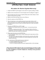
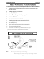
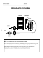
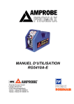
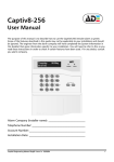
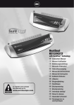
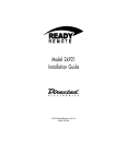
USER MANUAL
RG5410-E
Amprobe Test Measurement GmbH
Mittelstraße 3, 41236 Mönchengladbach
Telefon +49(0)2166/94991-0, Fax +49(0)2166/612168
Norsk forhandler: Moderne Kjøling AS, Gladengveien 1, 0661 Oslo
Tlf: 22087800 fax: 22087899
AMPROBE EUROPE
RG5410-E
TABLE OF CONTENTS
I) Safety Precautions
A) The Safe Way is the Only Way!
B) Refrigerant Gas Recovery & Containment
1
2
II) Important General Information
3
III) Operational Procedures
A) Operating Your RG5410 hp
B) Self Purging Your RG5410 hp
C) Set- up Procedures
D) Purging the Non-Condensable Gases
4
5
6,7,8
9
IV) Diagrams
A) Parts List
B) Refrigerant Flow Diagram
C) Wiring Diagram
D) Technical Data
10
11
12
13
V) Care and Maintenance
14
VI)
Safety Pressure Switch
15
VII)
Helpful Hints
16,17,18
Design specifications and material are subject to change without notice. REV032001TWH
This manual may not be reproduced in any way, shape or form without express written
consent of PROMAX AMPROBE
AMPROBE EUROPE
RG5410-E
THE SAFE WAY IS THE ONLY WAY!
NOTE! IF YOU ARE NOT A QUALIFIED REFRIGERANT SERVICE TECHNICIAN,
DO NOT USE THIS EQUIPMENT
1. The technician should always wear goggles and gloves when working on
refrigeration systems.
2. Be sure that any room where you are working is thoroughly ventilated,
especially if a leak is suspected. Refrigerant vapor is hazardous to your health
and can cause death.
3. Always think before acting. Familiarity breeds carelessness and carelessness
can be harmful to your health or, worse, result in death.
4. Read the Material Safety Data Sheets (MSDS) on all compounds with which
you are likely to come in contact. Read MSDS on refrigerant and refrigerant oil.
Obtain MSDS sheets from your refrigerant supplier.
5. Never use oxygen when testing for leaks. Any oil in contact with oxygen under
pressure will form an explosive mixture.
6. Refrigerant systems are generally electrically driven and controlled. Be sure to
disconnect the unit from the power source before servicing it.
7. Always store refrigerant containers in a cool, dry place.
8. Always open service and cylinder valves slowly. This allows quick control of the
flow of gasses if there is any danger. Once it is determined that there is no
danger, the valves may be opened fully.
9. Do not mix refrigerant in a system, a tank or anywhere else. Each type of
refrigerant must have its own tank, filters, etc.
10. If moisture enters the refrigerant system, it is likely to cause considerable
damage. Keep everything connected with the refrigeration system thoroughly
dry and clean.
11. This equipment should be used in locations with mechanical ventilation providing
at least four air changes per hour, or the equipment should be located at least
45cm (18”) above the floor. Do not use this equipment in the vicinity of spilled or
open containers of gasoline or any other flammable liquid.
-1-
AMPROBE EUROPE
RG5410-E
REFRIGERANT GAS
RECOVERY & CONTAINMENT
Safety comes first. Read all safety information for the safe handling of refrigerant
including the Material Safety Data Sheet provided by your refrigerant supplier. Never
operate unit in an explosive environment. Wear safety glasses and protective gloves.
Work area must be well ventilated. This unit should only be operated by a qualified
technician.
REFRIGERANT STORAGE CONTAINERS
***HANDLE WITH CARE**
CAUTION: Never use a standard disposable 30 lb. tank (the type of container in which
virgin refrigerant is sold) to recover refrigerant. Use only DOT CFR Title 49 or UL
approved storage containers for recovered refrigerant..
NOTE: Recovery cylinders are designed for different pressures.
DO NOT exceed the working pressure of each cylinder.
Safety codes recommend that closed tanks not be filled over 80% of volume with liquid.
The remaining 20% is called head pressure room.
NEVER TRANSPORT AN OVERFILLED CYLINDER
Refrigerant expands when it gets warm and may cause a tank to explode if overfilled.
Cylinder temp.
16 °C
21 °C
38 °C
54 °C
66 °C
80 %
81%
83%
90%
94%
90%
92%
96%
100%
STARTING WITH
CYLINDER 80%
FULL BY VOLUME
SPACE
OCCUPIED BY
LIQUID
STARTING WITH
CYLINDER 90%
FULL BY VOLUME
SPACE OCCUPIED
BY LIQUID
-2-
AMPROBE EUROPE
RG5410-E
IMPORTANT
GENERAL INFORMATION
BEFORE OPERATING THE RG5410 hp RECOVERY UNIT, READ THE
FOLLOWING
1) Always isolate large amounts of refrigerant and close off valves after use so if a leak
should develop anywhere in the system the refrigerant does not escape.
2) Storage cylinders sometimes have valves that are not properly seated when
manufactured. Keeping caps on these valves will guard against refrigerant leakage.
3) Always operate the unit on a flat level surface.
4) Your RG5410 hp has one internal pressure shut off switche. If the pressure inside the
system should go above 38,5 bar (550 psi), the system will automatically shut itself off.
CAUTION !
The 38,5 bar (550 psi) switch does not prevent tank overfill. If your system shuts off on
high pressure and is connected to your tank, you may have overfilled your tank and
created a very dangerous situation! Take immediate measures to relieve any high
pressure and/or tank overfill.
5) WARNING! Never overfill storage tanks. Overfilling may cause tanks to explode.
6) Tanks and filters should be designated for one refrigerant only. Before using a tank
previously used for another refrigerant, completely empty the tank, evacuate it, purge the
tank using dry nitrogen, and
re-evacuate it. Use only Promax Amprobe storage tank part No.
RGT30 hp or RGT50 hp with this refrigerant recovery equipment.
7) Special care should be taken when recovering from a burned-out system. Use two
high acid capacity filters, in series. Alco type
EK-162-F or Sporlan type C-162-F are recommended. When you have finished
recovering from the system, flush your RG5410 hp with a small amount of refrigerant oil
and a small amount of clean refrigerant to purge off any foreign substances left in the
unit.
8) Always empty refrigerant from the unit into a storage tank; see Self Purge/Auto
Evacuate procedure. Liquid refrigerant left in the condenser may expand, causing
damage to components
-3-
AMPROBE EUROPE
RG5410-E
OPERATING YOUR RG5410
Procedure for Normal System Recovery
1
Inspect the RG5410 hp thoroughly to insure that it is in good operating condition.
2. Make sure all connections are correct and tight (see set-up diagram on page 6).
3. Open the liquid port of the recovery cylinder (always open valves slowly to check
hoses and connections for leaks).
4. Make sure the Recover/Purge valve is set on Recover.
5. Open the output port of the RG5410 hp.
6. Open the liquid port on the manifold gauge set; opening the liquid port will
remove the liquid from the system first, greatly reducing the recovery time (after
the liquid has been removed, open the manifold vapor port to finish evacuating
the system).
7. Connect your RG5410 hp to a 230 V outlet.
a. Switch the main power switch to the ON position. You should hear the fan
running.
b. Press the compressor start switch. This "momentary" switch will start the
compressor; (It may be necessary, under certain circumstances, to press this
switch more than once to start the compressor.)
8. Slowly open the input port on the RG5410 hp .
a. If the compressor starts to knock, slowly throttle back the input valve until the
knocking stops.
b. If the input valve was throttled back, it should be fully opened once the liquid
has been removed from the system (the manifold vapor port should also be
opened at this time).
9. Run until minimum EPA required vacuum is achieved.
a. Close the manifold vapor and liquid ports.
b. Close the RG5410 hp input port.
c. Shut unit off and proceed with the Self Purge procedure on the next page.
Always purge the RG5410 hp after each use (see Self Purge procedure on page
5). Failure to purge the remaining refrigerant from the RG5410 hp could result in
the acidic degradation of internal components, ultimately causing premature
failure of the unit.
-4-
AMPROBE EUROPE
RG5410-E
SELF PURGING YOUR RG5410
Procedure for Purging Remaining Refrigerant From the RG5410
1
Close the ports of the system being serviced that are connected to the input
port of the RG5410.
2.
Close the input port on the RG5410.
3.
Turn off the RG5410.
4.
Turn the Recover/Purge valve to the purge position.
5.
Restart the RG5410.
6.
Run until desired vacuum is achieved.
7.
Close the ports on the recovery tank and the RG5410.
8.
Turn the RG5410 off.
9.
Return the Recover/Purge valve to the recover position.
10.
Disconnect and store all hoses.
11.
Replace the in-line filter on your RG5410 after every large
job or any time excessive contaminant is encountered.
SELF PURGE / AUTO EVACUATE
Note -
To change from Recovery mode to Purge:
Close the Input port, turn the unit off (to prevent high pressure
-5-
AMPROBE EUROPE
RG5410-E
shutoff),
switch to Purge position and restart the unit.
-6-
AMPROBE EUROPE
RG5410-E
SET-UP DIAGRAM FOR REFRIGERANT RECOVERY
This method is the fastest method for recovering vapor refrigerant..
(OPTIONAL)
INPUT
MANIFOLD GAUGE SET
OUTPUT
LIQUID
A scale must be used
to avoid overfilling the
storage tank
NORMAL RECOVERY
-7-
AMPROBE EUROPE
RG5410-E
RG5410 REFRIGERANT RECOVERY
ADDITIONAL INFORMATION
To achieve the deepest final vacuum, use the tank cooling method to lower the head
pressure on the recovery tank. Repeat as necessary to achieve the desired vacuum
level. NOTE: If there is no liquid in the recovery tank, then the cooling method will not
work. In this case, use an empty tank that has been fully evacuated to achieve the final
vacuum level required.
To maximize recovery rates use the shortest possible length of 3/8” or larger hose. A
hose no longer than 3’0” is recommend. Always remove all unnecessary hose core
depressors and Schrader valves from port connections (using the proper valve core
tool) for maximum throughput. Deformed rubber seals and core depressors in hoses
and faulty or unnecessary Schrader valves can restrict flow by up to 90%.
If the tank pressure exceeds 300 psi, use the tank cooling procedure to reduce the tank
pressure. When recovering large amounts of liquid, use the “PUSH/PULL” method of
recovery (see diagram below).
CAUTION: When using the “PUSH/PULL” method, you must use a scale to prevent
overfilling the storage tank. Once the “PUSH/PULL” siphon is started, it can continue
and overfill the storage tank even if the tank is equipped with a float level sensor. The
siphon can continue even when the machine is turned off. You must manually close the
valves on the tank and the unit to prevent overfilling the recovery tank.
SET-UP DIAGRAM FOR “PUSH/PULL” METHOD
Push pull only works with large systems where the liquid is readily accessible. Do not
use this method on systems that contain less than 15 pounds as it may not work.
INPUT
OUTPUT
VAPOR
OPTIONAL MOISTURE
INDICATIING SIGHT GLASS
The sight glass is used to provide a method of
determining the moisture content and quality of a
system’s refrigerant.
-8-
LIQUID
A scale must be
used to avoid
overfilling the
storage tank.
AMPROBE EUROPE
RG5410-E
-9-
AMPROBE EUROPE
RG5410-E
SET-UP DIAGRAM FOR TANK PRE OR SUB
COOLING PROCEDURE
To start you must have a minimum of
2,5 kg of liquid refrigerant in the tank.
INPUT
OUTPUT
Throttle the output valve so that the
output pressure is 7 bar (100 psi)
greater than the input pressure, but
never more than 31,5 bar (450 psi).
Run until the tank is cold.
VAPOR
LIQUID
OPTIONAL RECOVERY / TANK PRE OR SUB
COOLING FOR FIXED HOSE SET UP
INPUT
MANIFOLD GAUGE SET
OUTPUT
VAPOR
LIQUID
A SCALE MUST BE
USED TO AVOID
NORMAL RECOVERY:
Tank Vapor valve is closed.
TANK PRE OR SUB COOLING: Tank Vapor valve is open and both Manifold Gauge
Set valves are closed. Follow above procedure.
- 10
AMPROBE EUROPE
RG5410-E
RG5410 hp RECOVERY
PURGING THE NON-CONDENSABLE GASSES FROM IDENTIFIED
REFRIGERANT IN A TANK
1) Allow the tank to sit undisturbed for 24 hours. (This allows the air to rise to the top.
2) Connect a manifold to the tank and read the amount of pressure in the tank by
looking at the output pressure gauge.
3) Determine the ambient temperature in the room.
4) Refer to a Refrigerant pressure/temperature chart. Find the temperature on the
chart and look across to the corresponding pressure for the type of refrigerant in
the tank. Determine how that relates to the reading on the gauge.
5) If the pressure reading is higher than the pressure shown on the chart, very
slowly (so as not to cause turbulence inside the tank) crack open the vapor port
valve. Watch the pressure on the gauge decrease. To prevent venting, add 0,3 0,35 bar (4 - 5 psi) to the pressure shown on the chart. When the gauge
corresponds to that pressure, close the vapor port valve.
6) Allow the tank to sit for 10 minutes and check the pressure again.
7) Repeat the process again if necessary.
- 11
AMPROBE EUROPE
RG5410-E
PARTS LIST RG5410-E
Pos.
- 10- 12
1
2
3
4
5
6
7
8
9
10
11
12
13
14
15
16
17
18
19
20
21
22
Description
PLASTIC CASE
FAN GRILL
AXIAL FAN
CONDENSER
MOTOR
COUPLER
BELL HOUSING
COMPRESSOR
MANIFOLD
INPUT GAUGE
OUTPUT GAUGE
GAUGE LENS
ON/OFF SWITCH
START
BLUE KNOB
RED KNOB
BLACK KNOB
FRONT PANEL
FILTER
FLARE CAP
CORD SET
PRESSURE SW.
Part #
MC5000
SH5022
EL1818
CD1201
EL1822
CP1315
CP1001
CP1320
MA1020
GA1030
GA1080
GA1000
EL1310
EL1309
HA1003
HA1003
HA1003
SH5020
FL1201
NB6501
WR2003
EL2802
AMPROBE EUROPE
RG5410-E
REFRIGERANT-FLOW DIAGRAM
CONDENSER
COMPRESSOR
MOTOR
OUTPUT
- 11 -
INPUT
FILTER
NOTE: A filter must always be used. Failure to use a filter will invalidate your warranty.
The use of a filter will greatly reduce the risk of damage to your RG50410 hp by preventing foreign material from entering the unit.
Special consideration for filtration must be given when you know you are servicing a machine that has "Burned Out".
We recommend the use of two size 162 filter driers, in line, to be used for that job and that job only.
- 13
AMPROBE EUROPE
RG5410-E
RG5410-E WIRING DIAGRAM
Plug AC Male
Power
sw switch
High Pressure switch
rt
rt
ge
ge
Motor,
1/2 PS
gn
gn
ws
Fan motor
ge
- 12 -
gn
Start switch
ws
3
- 12
bl
AMPROBE EUROPE
RG5410-E
Technical Specifications RG 5410-E
Application
Refrigerant recovery Gas or Vapor
Suitable Refrigerants
R11,R12, R13B1, R123, R134a, R141b, R22, R23,
R401A, R401B, R402A, R402B, R404A, R407A,
R407B, R407C, R408A, R409A, R410A, R500, R502,
R503, R507
Power Source
230V/50Hz
Power
380 W
Dimensions
343 x 229 x 483
Weight
14 kg
Recovery Rate
Vapor
Liquid
Push Pull
Displacement
8,2 cm3
Rpm’s
1437 U/min
Max Working Pressure
550 p.s.i. (38,5 bar)
Safety Device
Safety pressure switch type P100 DA
with manual reset (550 p.s.i. / 38,5 bar)
up to 33 Kg/h
up to 80 Kg/h
up to 380 Kg/h
ATTENTION:
The RG5410-E should not be used with inflammable
gases nor with gases containing ammonia.
- 13 -
AMPROBE EUROPE
RG5410-E
CARE AND MAINTENANCE OF YOUR
RG5410 hp
A filter must always be used and should be replaced frequently. Failure to use a filter will
invalidate your warranty. The use of a filter will greatly reduce the risk of damage to your
RG5410 hp by preventing foreign material from entering the unit.
Special consideration for filtration must be given when you know the machine you are
servicing has "burned out". We recommend the use of two size 162 filter driers, in line, to
be used for that job and that job only. We also recommend that a clean filter be used for
every service job. Each filter should be labeled and used exclusively for one type of
refrigerant only.
Do not use this unit in the vicinity of spilled or open containers of gasoline or other
combustible liquids
Avoid the use of extension cords. If you must use an extension cord it should be a
minimum of 12 AWG and not longer than 15 ft. Not using an extension cord will greatly
reduce the risk of fire.
Always purge the unit of any refrigerant left after completing a service job. Refrigerant left in
the machine can expand and may cause damage to components.
If the unit is to be stored or not used for any length of time, we recommend that it be
completely evacuated of any residual refrigerant and purged with dry nitrogen.
Whenever you perform any type of maintenance work on your RG5410 hp, insure that it is
disconnected from the power supply before you begin.
- 14 -
AMPROBE EUROPE
RG5410-E
Safety Pressure Switch (with manual reset function)
The RG5000 is equipped with an internal Safety Pressure Switch. If the pressure inside the
system exceeds 27,5 bar, the system is switched off automatically.
If the Safety Pressure Switch is activated automatically whilst filling a bottle, it could be
caused by the bottle becoming overfilled.
THIS IS A VERY DANGEROUS SITUATION! You should take steps immediately to reduce
the overpressure and/or to eliminate the overfilling of the bottle.
If the Safety Pressure Switch switches the unit off...
The following precautions should be taken if the Safety Pressure Switch is activated:
a) Suspected overfilling of the recovery bottle,
Connect the recovery bottle to another bottle with spare capacity so that the pressure is
reduced to a safe level. This action should also reduce the pressure in the output line from
the RG5000. Proceed as normal after resetting the Safety Pressure Switch (see below).
b) Cause of activation of Safety Pressure Switch unknown,
Check that the recovery bottle is not overfilled.
Close the system valves, recovery bottle valves and RG5000 valves.
Disconnect RG5000 from flexible pipes.
Disconnect RG5000 from the power supply.
Open the input and output valves very slowly.
Investigate the reason for the failure.
Once activated the Safety Pressure Switch has to be reset manually as follows:
Remove the black protection cover to reveal the reset button (see picture below).
Reset by pushing the reset button with a tool such as a screwdriver.
Replace the cover.
- 15 -
AMPROBE EUROPE
RG5410-E
- 16 -
AMPROBE EUROPE
RG5410-E
Helpful Hints for Refrigerant Recovery
Refrigerant recovery has come a long way in a few short years.
On the surface it’s simply the process of taking refrigerant out of a system and putting it into
a tank. However, this simple process can quickly become problematic if a few items are
overlooked. The following are some tips and pointers we’ve accumulated over the last few
years that can save you time and make the process go smoother.
First you need to identify the refrigerant type and quantity in the system you are
servicing.
If you determine it’s a burnout, you need a special tank (a tank that’s identified as
containing burnout or other unidentified gases), and you need to use extra filtration prior to
recovery.
If, on the other hand, you know the gas in the system is relatively clean or new, then a new
tank should be used. If you’re planning on putting the refrigerant back into the same system
after you have finished the service or if the refrigerant is going to be reclaimed, then use a
tank that has the same refrigerant in it. A word of caution about the Environmental
Protection Agency (EPA): If you use a variety of refrigerant gasses in your service work as evidenced by your refrigerant purchases - and you only own one tank, you are asking for
trouble. You would be well advised to own at least one tank for every refrigerant type
serviced, plus an extra for burnouts and other unknowns.
Planning Ahead
Knowing the quantity of refrigerant is important for planning storage requirements, as well
as planning for the actual recovery. For instance, any system with more than 5lbs. of
refrigerant is likely to have areas where the liquid can get trapped.
The key to a quick recovery procedure is to get the liquid out first, and then get the
remaining vapor out. However most systems are not “recovery friendly.” That is they don’t
have access ports at their lowest points. If some units you’re servicing are on maintenance
contracts, you would save significant time by installing access ports at all of the lowest
points in the system, where liquid is likely to accumulate. Since most systems don’t have
these ports you need to be prepared to boil of the trapped liquid with a heat gun, when ever
it’s found. An indicator of trapped liquid in a system is frost or condensation forming on the
plumbing or components where the liquid is trapped. The trapped liquid may be in an area
that is not visible. In all cases trapped liquid in a system during recovery causes the
recovery process to slow down, regardless of the size or type of machine
If you are unable to locate the trapped liquid (but you know it’s there, because the recovery
job is taking “forever”), turn on the system compressor (if it’s operable) for a few seconds.
This will get the refrigerant moving to another part of the system and in.
- 17 -
AMPROBE EUROPE
RG5410-E
Hoses and Valves
Hoses and Schraeder valves have a large impact on recovery speed. In general, the
larger the hose, the less friction on the flow of refrigerant, the quicker the recovery time.
Many contractors are now using 3/8” lines for the input to the recovery machine, even if
those lines originate out of 1/4” fittings.
Schraeder valves must be removed from the connection prior to an expedient
recovery. Most wholesalers sell a tool for removing these cores, while keeping the
connection sealed. The core depressor, in the end of the hose, should also be removed.
These two items can turn a 20 minute job into one that goes on for hours. So, be sure to
remove Schraeder valves and core depressors before every recovery job.
Another hose consideration is the little rubber grommet at the end of the hose that makes
a seal with the flare fitting. We’ve seen these seals so worm and deformed that when the
hose is connected to the flare fitting the grommet virtually seals off the the connection. This
is probably never noticed in charging, because the pressure opens the grommet, but
during recovery (or with suction) the deformed grommet severely restricts the flow of
refrigerant.
Refrigerant Recycling
Current regulations state that used refrigerant shall not be sold, or used in a different
owner’s equipment, unless the refrigerant has been laboratory analyzed and found to meet
the requirements of ARI 700 (latest edition). As a result, recycling and verifying ARI 700
conformance isn’t economically justified in most cases. It’s still a great idea to do as much
cleaning of refrigerant going back into the same system (or owners
system) as possible. We recommend using the largest, high-acid capacity filter that are
economically feasIble. Put these filters on the suction or inlet side of the recovery unit.
Change filters often.
The recovery of large amounts of liquid refrigerant can sometimes carry with it large
quantities of oil, if the system being serviced doesn’t have an adequate oil separator
installed. If this recovered refrigerant isn’t going to be liquid charged back into the same
system, you might want to separate the refrigerant from the oil in order to
measure the oil (to know how much oil to charge back into the system). However refrigerant
sent back for reclaim does not need to have the oil removed. One of the simplest and most
cost effective ways to achieve this is to use a 30 or 50 lb. tank in line with your recovery
machine. Connect the the system to the liquid port of the tank then from the vapor port of
the tank connect to the input of your recovery machine a second tank, for storing refrigerant,
should then be connected to the output of the recovery machine. If you encounter large
amounts of liquid you will need to put a band heater around the first tank.
When the recovery job is complete the oil can be removed, from the first tank, by applying
a small amount of pressure, using nitrogen, to one of the ports and
expressing the oil from the other. If you are going to remove the oil from the vapor port you
will need to turn the tank upside down. Always wear safety glasses when
performing this operation as the oil may be acidic and could cause severe burning
- 18 -
AMPROBE EUROPE
RG5410-E
Keeping the Dirt Out
During the recovery process your recovery machine can be exposed to debris that can,
potentially, damage it. Including brazing spatter and copper and brass slithers. Further
contamination can be introduced from the refrigerant storage tanks. To
prolong the life of your recovery machine always use an in-line filter.
Whenever you are charging a system from a recovery cylinder it is a good idea to use an
in-line filter to protect the system from contamination. Again, change your
in-line filters often.
Getting the Liquid Out (See diagram on page 7 of this manual)
Push-pull is a method of removing bulk liquid from a system using the pressure
differential created by the recovery machine. Push-pull will generally not work on smaller
systems because there is no bulk liquid reservoir to create a siphon from.
Push-pull is mostly used on systems with a receiver tank or those with greater than 20 lbs.
of refrigerant, or when transferring from one tank to another. The rate of liquid transfer id
very much dependent on hose size, with larger hoses providing much
better throughput.
Another trick is to chill the tank, if it’s partially filled, prior or during recovery. This operation
will lower the pressure in the storage tank and therefore speed up recovery.
There must be a minimum of 5 lbs of liquid refrigerant in the tank you wish to chill. This
operation can be performed prior to or during the recovery. See the two set up diagrams
and procedures on page 8 of this manual.
There is nothing magic here, you are simply using your recovery machine to make a
refrigerator where the tank is the evaporator. By throttling the output valve, you’re effectively
creating a capillary tube or an expansion device, but you need to adjust the back pressure
to suit the conditions and the refrigerant. Five to ten minutes of chilling can produce some
very dramatic tank cooling, depending on the conditions. If there are any non condensibles
in the tank this process will not work. Also the greater the quantity of refrigerant in the tank
the longer the process will take.
- 19 -