1
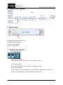
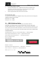
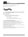
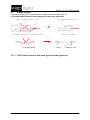
USER’S MANUAL
DMX 512 DRIVER
DMX 512 DRIVER
Table of contents
1. Safety instructions ........................................................................................................................... 3 2. SUMMARIZE ................................................................................................................................... 4 3. Features........................................................................................................................................... 4 4. TECH. CHARACTERISTICS ........................................................................................................... 4 5. Internal Block Digram ...................................................................................................................... 5 6. Appearance ..................................................................................................................................... 5 7. Interface Introduction ....................................................................................................................... 5 8. How To Use ..................................................................................................................................... 6 9. TYPICAL APPLICATIONS .............................................................................................................. 6 9.1. Connecting of DMX-512 Signal ............................................................................................... 7 9.2. Calculate the power ................................................................................................................. 7 10. DMX-512 Address Setting ........................................................................................................... 7 11. The contents about the product install and usage Principle: .................................................... 8 11.1. The contents about install and usage ...................................................................................... 8 12. Install Cases: ............................................................................................................................... 9 12.1.1.
13. (2)The install manners with weak signal and the right ways : ......................................... 9
Troubleshooting Guide .............................................................................................................. 10 If still can not figure out, please contact our technician......................................................................... 10 2 / 11
DMX 512 DRIVER
1. Safety instructions
FOR SAFE AND EFFICIENT OPERATION
Be careful with heat and extreme temperature Avoid exposing it
to direct rays of the sun or near a heating appliance.
Not put it in a temperature bellow 41°F /5°C, or exceeding 95°F /35°C.
Keep away from humidity, water and dust
Do not place the set in a location with high humidity or lots of dust.
Containers with water should not be placed on the set.
Keep away from sources of hum and noise
Such as transformer motor, tuner, TV set and amplifier.
To avoid placing on un-stable location
Select a level and stable location to avoid vibration.
Do not use chemicals or volatile liquids for cleaning
Use a clean dry cloth to wipe off the dust, or a wet soft cloth for stubborn dirt.
If out of work, contact sales agency immediately
Any troubles arose, remove the power plug soon, and contact with an engineer for repairing,
do not open the cabinet by yourself, it might result a
danger of electric shock.
3 / 11
DMX 512 DRIVER
2. SUMMARIZE
Thank you for using DV512 decoder. With advanced micro-computer control
technology, PX series convert the widely used DMX512/1990 signal to analog signal. Can
choose 1~3 output channel,256-level brightness control. For connecting of light console
and analog device, or lighting&building lamps controlling.
3. Features
◆ Meets
DMX512/1990
◆ 256-level
◆3
brightness, full-color control
output CH., can drive 5A(Each CH.)
◆ With
control system, can express perfect effect
◆ Can
drive 1~3 channel of each lamp
◆ Can
set the DMX address freely
◆ Modularizing,
can be combined with LED module neatly
4. TECH. CHARACTERISTICS
Decode CH.:
1~3
Input Signal:
DMX-512/1990 digital signal
Output Signal:
0~24V PWM signal,can drive 5A(Each CH.)
Power Supply:
DC,+12~25V
Power Dis.:
<1W
Power Output:
180W/12VDC 240W/24VDC
Operating Temp.:
0~70℃
Size:
175(mm)*45(mm)*35(mm),can be custom-made
Weight:
≤300g
4 / 11
DMX 512 DRIVER
5. Internal Block Digram
6. Appearance
(1) DMX signal input interface(RJ11)
(2) DMX signal output interface(RJ11)
(3) Address setting interface
(4) Driver output interface
(5) Power input interface
7. Interface Introduction
-
DMX signal interface
-
Address setting interface
Please find the detailed instruction for Address setting at Page 7.
-
Power input interface
DC 12-25V input,supply power for decoder and the lamps it takes.
-
Driver output interface
Common anode,V+ and R,G,B interface,can drive kinds of RGB module or single-color
module, Can regulate output current according to the actual load.
5 / 11
DMX 512 DRIVER
remark:
Connect the anode and RGB wire of common anode RGB module to the output interface of deoder
directly; Connect the anode wire of single-color module to V+ on decoder,and connect the cathode
wire to one of RGB pin according to the LED's color; Connect several colors single-color module to
one decoder,please connect their anode wires to V+ pin on decoder.
8. How To Use
DV512 is controlled by DMX-512 digital signal。The frontage is DMX512 transmitter, take IMGDMX512 for example, to control 0~24V analog devices. We suppose to drive LED to introduce it. The
connecting is below:
9. TYPICAL APPLICATIONS
◆ Circuit
Diagram 1
6 / 11
DMX 512 DRIVER
9.1. Connecting of DMX-512 Signal
◆
The wire for DMX signal is STP,the DMX signal has positive and negative signal.
Pay attention to the polarity while soldering. Connect the positive signal, negative
signal and GND to the corresponding signal of IMG-DV512.
◆
Connect a signal terminal at the end of the whole connection.
9.2. Calculate the power
This product has a wide input/output voltage(DC 6-25V),it's rating current is 5A,so the rating power
is different in different input,for example:
Rating power in 12V:180 W
Rating power in 24V: 360 W
10.
DMX-512 Address Setting
The DIP switch on IMG-DV512 can set the binary value of the DMX512 address to
receive data. The correlative bits is the 1-9 bits of the DIP switch, the 1st bit is LSB, the 9th
bit MSB 512 addresses totally. The start address is the no. of the first channel of the decoder ,the
second channel will receive the data of start addess+1,and the third channel will receive the data of
start addess+2.There are two way to find out the relation between the DIP switch and DMX address.
calculational method:
calculational formula:[the sum of 1~9 bit of the DIP switch] + 1 = DMX start address
Set the n(th) bit of the DIP switch up(set to“1”)to get the value of such bit;
Set the n(th) bit of the DIP switch down “0”),so the value of this bit is 0.
Note:the 10th bit is not use.
Value of each DIP:
Example 1:Set to 38
Set the 6th,3rd,1st bit of the DIP switch to“1”,others set to“0”,then the sum
of the 1~9 is 32+4+1,then add 1 to it,is the start address 38.
That is:[ 32 + 4 + 1 ] + 1 = 38
7 / 11
DMX 512 DRIVER
Example 2:Set to 226
Set the 8th,7th,6th,1st bit to “1”,others set to“0”,then the sum of the 1~9 is
128+64+32+1,then add 1 to it,is the start address 226.
That is:[ 128 + 64 + 32 + 1 ] + 1 = 226
11.
The contents about the product install and usage Principle:
(1)The input voltage should be limited in rated range.
(2)Do not use it by over load.
(3)Installed in suited environment.
A.The driver can not be setting in high temperature or wet conditions
B.We recommend three ways to take away the heat as follows
①Bared in moving air
②Put in a big enough space for taking away the heat
③Fixed on big metalline board, and make sure they are contacted well
11.1.
The contents about install and usage
(1)When work with controller, put the controller close to to avoid the signal become weak.
(2)Recommend to use the STP with the characteristic impedance of 120 ohm
(3)The signal line should be one bus, and the signal line pass in and out the decoder ports directly
(4)Make sure the signal line connector and the decoder's signal port are well connect
(5)Add a signal terminator at the end of the signal line
(6)The decoder should be closed to the lamps. If the lamps is over 5 meters, the ones follow should
be joined at the decoder's out port again
(7)Adopt thicker power cable with good conductibility
(8)If one decoder take several lamps in series , make sure the lamps' connectors are firmly connected
(9)Signal line should be far away with the 110/220V AC cable
8 / 11
DMX 512 DRIVER
12.
Install Cases:
(in attached drawing,the unconscionable of install cases were labeled by "X")
(1)The bad install manners of take away the heat and the right ways:
12.1.1. (2)The install manners with weak signal and the right ways :
9 / 11
DMX 512 DRIVER
13.
Troubleshooting Guide
If still can not figure out, please contact our technician.
10 / 11
DMX 512 DRIVER
Importeur:
B&K Braun GmbH
Industriestraße 1
D-76307 Karlsbad-Ittersbach
www.bkbraun.com
[email protected]
11 / 11