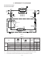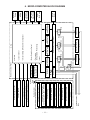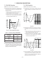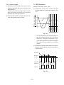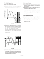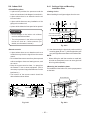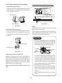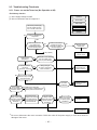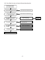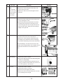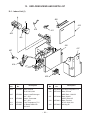
1
T O S H IB A F IL E N O . A 0 0 -9 6 1 9 S E R V IC E M A N U A L A IR -C O N D IT IO N E R R A S -1 0 S K H -E R A S -1 0 S K H X S P L IT W A L L T Y P E R A S -1 0 S A H -E R A S -1 0 S A H X P R IN T E D IN J A P A N , N o v .,1 9 9 6 T o M o CONTENTS 1. SPECIFICATIONS ............................................................................................................ 4 2. CONSTRUCTION VIEWS ................................................................................................ 6 2-1. Indoor Unit .................................................................................................................................. 6 2-2. Outdoor Unit ............................................................................................................................... 7 3. WIRING DIAGRAM .......................................................................................................... 8 4. SPECIFICATIONS OF ELECTRICAL PARTS ................................................................. 9 4-1. Indoor Unit .................................................................................................................................. 9 4-2. Outdoor Unit ............................................................................................................................... 9 5. REFRIGERANT CYCLE DIAGRAM .............................................................................. 10 6. MICRO-COMPUTER BLOCK DIAGRAM .......................................................................11 7. OPERATION DESCRIPTIONS....................................................................................... 12 7-1. FAN ONLY Operation ............................................................................................................... 12 7-2. COOL Operation ....................................................................................................................... 12 7-2-1. Louver Control ...................................................................................................................................... 13 7-3. DRY Operation .......................................................................................................................... 13 7-4. HEAT Operation ........................................................................................................................ 14 7-4-1. Louver Control ...................................................................................................................................... 14 7-4-2. Cool Airflow Control ............................................................................................................................. 14 7-5. AUTO Operation ....................................................................................................................... 15 7-5-1. Temporary Auto ..................................................................................................................................... 15 7-6. ECONO. Mode ........................................................................................................................... 16 7-6-1. Cooling ................................................................................................................................................... 16 7-6-2. Heating ................................................................................................................................................... 16 7-7. 7-8. 7-9. 7-10. 7-11. Current Limit Control ............................................................................................................... 16 High-Temperature Limit Control (Heating Operation) .......................................................... 17 Low-Temperature Limit Control (Cooling Operation) .......................................................... 17 Cool Airflow Prevention Control (Heating Operation) ......................................................... 17 Defrost Operation ..................................................................................................................... 18 7-11-1. Condition to Start the Defrost Operation ............................................................................................ 18 7-11-2. Defrost Operation Time Control .......................................................................................................... 18 7-11-3. Ending Condition at Defrost Operation .............................................................................................. 18 7-12. Auto Restart Function ............................................................................................................. 19 7-12-1. How to Set the Auto Restart ................................................................................................................. 19 7-12-2. How to Cancel the Auto Restart .......................................................................................................... 20 7-12-3. In Case of Power Failure during the Timer Operation .......................................................................20 8. INSTALLATION PROCEDURE ...................................................................................... 21 8-1. Safety Cautions ........................................................................................................................ 21 8-2. Installation Diagram of Indoor and Outdoor Units ............................................................... 23 8-3. Installation ................................................................................................................................ 24 8-3-1. Optional Parts ........................................................................................................................................24 8-3-2. Kit Parts ................................................................................................................................................. 25 – 2 – 8-4. Indoor Unit ................................................................................................................................ 26 8-4-1. 8-4-2. 8-4-3. 8-4-4. 8-4-5. 8-4-6. Cutting a Hole and Mounting Installation Plate .................................................................................26 Electrical Work ...................................................................................................................................... 27 Wiring Connection ................................................................................................................................ 28 Piping and Drain Hose Installation ...................................................................................................... 30 Indoor Unit Installation ......................................................................................................................... 31 Drainage ................................................................................................................................................. 31 8-5. Outdoor Unit ............................................................................................................................. 32 8-5-1. Refrigerant Piping Connection ............................................................................................................ 33 8-5-2. Vacuum Pumping .................................................................................................................................. 33 8-5-3. Wiring Connection ................................................................................................................................ 34 8-6. Others ........................................................................................................................................ 35 8-6-1. Gas Leak Test ........................................................................................................................................35 8-6-2. Test Operation ....................................................................................................................................... 35 8-6-3. Auto Restart Setting ............................................................................................................................. 35 9. TROUBLESHOOTING CHART...................................................................................... 36 9-1. What to be Prechecked First .................................................................................................. 36 9-1-1. Power Supply Voltage ........................................................................................................................... 36 9-1-2. Incorrect Cable Connection between Indoor and Outdoor Units ..................................................... 36 9-1-3. Misleading but Good Operations .........................................................................................................37 9-2. Primary Judgement of Trouble Sources ............................................................................... 38 9-2-1. Role of Indoor Unit Controller .............................................................................................................. 38 9-2-2. Display of Abnormalities and Judgement of the Abnormal Spots ................................................... 38 9-3. Troubleshooting Flowcharts ................................................................................................... 42 9-3-1. 9-3-2. 9-3-3. 9-3-4. 9-3-5. 9-3-6. 9-3-7. Power can not be Turned on ................................................................................................................42 Power can not be Turned on after Replacing Indoor PC Board ....................................................... 43 Outdoor Unit does not Operate ...........................................................................................................43 Only Compressor does not Operate ................................................................................................... 44 Only Outdoor Fan does not Operate ................................................................................................... 45 Only 4-Way Valve does not Operate ....................................................................................................46 Only the Indoor Fan does not Operate ................................................................................................ 47 9-4. How to Check the Remote Control (Including the Indoor PC Board) ................................ 48 9-4-1. How to Check the PC Board ................................................................................................................. 49 9-4-2. PC Board Layout ...................................................................................................................................51 9-4-3. How to Reduce the Operation Time of the Anti-Restart Timer .........................................................52 10. PART REPLACEMENT ................................................................................................. 53 10-1. Indoor Unit ................................................................................................................................ 53 10-2. Microcomputer ......................................................................................................................... 55 10-3. Outdoor Unit ............................................................................................................................. 56 11. CAUTIONS ON REPLACEMENT OF PC BOARD ASSEMBLY .................................... 57 12. EXPLODED VIEWS AND PARTS LIST ......................................................................... 58 12-1. Indoor Unit (1) ........................................................................................................................... 58 Indoor Unit (2) ........................................................................................................................... 59 Indoor Unit (3) ........................................................................................................................... 60 12-2. Outdoor Unit ............................................................................................................................. 61 – 3 – 1. SPECIFICATIONS RAS-10SKH-E/10SAH-E, RAS-10SKHX/10SAHX Model Item COOLING Capacity Power source Power consumption Power factor Running current Starting current Moisture removal Noise Refrigerant Indoor (H/M/L) Outdoor (220/230/240V) Name of refrigerant Rated volume Phase V Hz kW % A Indoor/Outdoor A lit/h dB dB kg Refrigerant control Interconnection pipe Condensate drain pipe INDOOR UNIT Dimensions Gas side size Connection type Liquid side size Connection type Maximum length (of one way) Maximum height difference Indoor unit ↑ Outdoor unit ↓ mm Outer diameter mm Height Width Depth mm mm mm kg High fan Medium fan Low fan m 3/h m 3/h m 3/h W Height Width Depth mm mm mm kg Net weight Evaporator type Indoor fan type Air volume Fan motor output Air filter OUTDOOR UNIT Dimensions Net weight Condenser type Outdoor fan type Airflow volume Fan motor output Compressor 220V 2.65 *1 kW mm m Safety device Auto louver Usable outdoor temperature range 240V 2.70 220V 3.00 230V 3.05 240V 3.10 Single 220/230/240 50 0.98/0.99/1.02 95/92/90 0.89/0.90/0.91 95/92/88 220V 230V 240V 220V 230V 240V 0.11/4.58 0.11/4.57 0.11/4.61 0.11/4.17 0.11/4.16 0.11/4.22 19 1.2 41/36/31 47/48/49 R-22 0.74 Capillary tube 9.52 Flare connection 6.35 Flare connection 10 *2 5 m 16 RAS-10SKH-E/RAS-10SKHX 265 790 174 8 Finned tube Cross flow fan 600 500 400 19 Polypropylene net filter (Washable) RAS-10SAH-E/RAS-10SAHX 530 770 200 31 Finned tube Propeller 1600 18 PH120T1-4C 750 Fuse, Overload relay Yes m 3/h W Model Output 230V 2.68 HEATING W °C 21 ~ 43 Specifications are subject to change without notice. – 4 – – 5 ~ 21 Note : *1 • Capacity is based on the following temperature conditions. Condition Temperature JIS C9612-1994 Cooling Heating (DB) 27°C 20°C (WB) 19°C 12°C (DB) 35°C 7°C (WB) 24°C 6°C Indoor unit inlet air temperature Outdoor unit inlet air temperature Notes : *2 CHARGELESS • No additional refrigerant required. • This air conditioner accepts a connection piping length of up to 10m and a head of up to 5m. • There is no need to add the refrigerant as long as the total length of the connection piping is up to 10m. – 5 – 2. CONSTRUCTION VIEWS 2-1. Indoor Unit RAS-10SKH-E RAS-10SKHX Heat exchanger Air filter 790 ,,,,,,,,,,,,,,,,,,,,,,,,,,,,,,,,,,,,,,, ,,,,,,,,,,,,,,,,,,,,,,,,,,,,,,,,,,,,,,, ,,,,,,,,,,,,,,,,,,,,,,,,,,,,,,,,,,,,,,, ,,,,,,,,,,,,,,,,,,,,,,,,,,,,,,,,,,,,,,, ,,,,,,,,,,,,,,,,,,,,,,,,,,,,,,,,,,,,,,, ,,,,,,,,,,,,,,,,,,,,,,,,,,,,,,,,,,,,,,, ,,,,,,,,,,,,,,,, ,,,,,,,,,,,,,,,,,,,,,,,,,,,,,,,,, ,,,,,,,,,,,,,,,,,,,,,,, ,,,,,,, ,,,,,,,,,,,,,,,,,,,,,,,,,,,,,,,,,,,,,,,, ,,,,,,,,,,,,,,,,,,,,,,,,,,,,,,,,,,,,,,,, ,,,,,,,,,,,,,,,,,,,,,,,,,,,,,,,,,,,,,,,, ,,,,,,,,,,,,,,,,,,,,,,,,,,,,,,,,,,,,,,,, ,,,,,,,,,,,,,,,,,,,,,,,,,,,,,,,,,,,,,,,, ,,,,,,,,,,,,,,,,,,,,,,,,,,,,,,,,,,,,,,,, ,,,,,,,,,,,,,,,,,,,,,,,,,,,,,,,,,,,,,,,, ,,,,,,,,,,,,,,,,,,,,,,,,,,,,,,,,,,,,,,,, ,,,,,,,,,,,,,,,,,,,,,,,,,,,,,,,,,,,,,,,, ,,,,,,,,,,,,,,,,,,,,,,,,,,,,,,,,,,,,,,,, ,,,,,,,,,,,,,,,,,,,,,,,,,,,,,,,,,,,,,,,, ,,,,,,,,,,,,,,,,,,,,,,,,,,,,,,,,,,,,,,,, ÀÀÀÀÀÀ ,,,,,, @@@@@@ ,,,,,, @@@@@@ ÀÀÀÀÀÀ ,,,,,, @@@@@@ ÀÀÀÀÀÀ 50 265 ,,,,,,,, ,,,,,,,, ,,,,,,,, ,,,,,,,, ,,,,,,,, ,,,,,,,, ,,,,,,,, ,,,,,,,, ,,,,,,,, ,,,,,,,,,,,,,,,,,,,,,,,,,,,,,, ,,,,,,,,,,,,,,,,,,,,,,,,,,,,,, ,,,,,,,,,,,,,,,,,,,,,,,,,,,,,, ,,,,,,,,,,,,,,,,,,,,,,,,,,,,,, ,,,,,,,,,,,,,,,,,,,,,,,,,,,,,, ,,,,,,,,,,,,,,,,,,,,,,,,,,,,,, ,,,,,,,,,,,,,,,,,,,,,,,,,,,,,, ,,,,,,,,,,,,,,,, ,,,,,,,,,,,,,,, ,,,,,,,,,,,,,,,,,,,,,,,,,,,,,,, ,,,,,,,,,,,,,,,,,,,,,,,,,,,,,,, ,,,,,,,,,,,,,,,,,,,,,,,,,,,,,,, ,,,,,,,,,,,,,,,,,,,,,,,,,,,,,,, ,,,,,,,,,,,,,,,,,,,,,,,,,,,,,,, ,,,,,,,,,,,,,,,,,,,,,,,,,,,,,,, ,,,,,,,,,,,,,,,,,,,,,,,,,,,,,,, ,,,,,,,,,,,,,,,,,,,,,,,,,,,,,,, ,,,,,,,,,,,,,,,,,,,,,,,,,,,,,,, ,,,,,,,,,,,,,,,,,,,,,,,,,,,,,,, ,,,,,,,,,,,,,,,,,,,,,,,,,,,,,,, ,,,,,,,,,,,,,,,,,,,,,,,,,,,,,,, 174 10SKH-E : Without power cord 10SKHX : With power cord 1800 Air outlet 47 10 Air inlet Knock out system 790 232 326 Front panel 232 Back body Hanger Drain hose (0.54m) 10 50 47 321 Hanger Knock out system 65.5 659 Hanger For stud bolt (ø8~ø10) Wireless remote control For stud bolt (ø6) 20 2.5 Minimum distance to wall 120 or more 55 Minimum distance to wall 20 46 20 120 or more 319 269 112.8 Hanger Installation plate outline Center line 76 40.5 40.5 3.5 Hanger 59.6 60.5 126 790 – 6 – 16 Remote control holder 37 17 65.5 450 326 66 or more Minimum distance to ceiling Hanger 265 Connecting pipe (0.49m) (Flare ø6.35) 136 Connecting pipe (0.39m) (Flare ø9.52) 5 2-2. Outdoor Unit RAS-10SAH-E RAS-10SAHX Detail Drawing 600 A Gas side (flare ø9.52) ø25 Drain hole 30 230 216 25 ø11x14 Hole 85 R10 230 36 50 600 111 36 216 A Liquid side (flare ø6.35) 50 ø6 Hole 8-ø6 Holes (For fixing the outdoor unit) Handle 11 Fan guard 111 200 12 4-ø11x14 Long holes (For anchor bolt ø8-ø10) ø420 11 TOSHIBA Electric parts cover 525 530 Z 62 268 54 89 Access for charging 250 59 89 268 5 770 59 770 View 600 Inlet port 600 or more Inlet port 100 or more Visible outline (Minimum distance of the product of the wall) 200 or more 230 45 or more Z Outlet port 4-ø11x14 Long holes (For anchor bolt ø8-ø10) Center port Mounting dimension of anchor bolt – 7 – 3. WIRING DIAGRAM Section A LOUVER MOTOR THERMAL FUSE 77˚C × 2 L N 3 3 CN04 1 1 GRN&YEL Section A 5 4 3 2 1 5 4 3 2 1 CN10 MAIN P.C. BOARD MCC-713 R116 VARISTOR F01 FUSE P04 DSA BRW L N 6 5 4 3 2 1 CN07 6 5 4 3 2 1 R109 SG01 BLK IC04 R01 T3.15A 250V C01 BLU 3 POWER TERMINAL BLOCK 3 RY02 FAN MOTOR WHI BLU YEL BLK RED RAS-10SKHX/SAHX 220/230/240V ~ 50Hz DC MOTOR BLU PNK YEL ORN RED BRW L N GRY RAS-10SKH-E/SAH-E 220/230/240V ~ 50Hz GRY Model R21 C15 DB01 C02 T01 DC35V L01 DC12V RY01 4 4 DC7V BLK T02 C.T. DC0V WHI C06 IC02 IC IC01 1 2 3 4 5 6 7 8 9 1 2 3 4 5 6 7 8 9 CN25 CR02 1 2 CN03 1 2 1 2 CN01 1 2 BLK BLK BLU BLU BLU BLU BLU BLU PNK BLK WHI CR01 1 1 2 3 4 4 CN13 BLK BLK 1 2 3 4 5 6 7 8 9 RY03 RY04 INFRARED RAYS RECEIVE AND INDICATION PARTS THERMO SENSOR (TA) BLK WHI RED BLU GRN&YEL CN27 INDOOR TERMINAL 1 2 3 4 BLOCK HEAT EXCHANGER SENSOR (TC) DSA : Surge absorber C.T : Current trans INDOOR OUTDOOR OVER LOAD RELAY 1 2 3 4 BLK BLK RED BLK COMPRESSOR PNK WHI BLK GRN & YEL CHASSIS RUNNING SOLENOID CAPACITOR COIL RED RUNNING CAPACITOR RED WHI BLK FAN MOTOR – 8 – COLOR IDENTIFICATION BRW : BROWN RED : RED WHI : WHITE YEL : YELLOW BLU : BLUE BLK : BLACK GRY : GRAY PNK : PINK ORN : ORANGE GRN&YEL : GREEN & YELLOW 4. SPECIFICATIONS OF ELECTRICAL PARTS 4-1. Indoor Unit RAS-10SKH-E RAS-10SKHX No. Parts name 1 Fan motor (for indoor) 2 Thermo sensor (TA-sensor) 3 DC-DC transformer (T01) 4 Microcomputer 5 Power relay (RY01), Common relay (RY02) 6 Heat exchanger sensor (TC-sensor) 7 Line filter (L01) 8 Diode (DB01) 9 Capacitor (C02) 10 Fuse (F01) 11 Relay (for outdoor fan motor, solenoid coil) (RY03, RY04) 12 Power supply IC (IC01) 13 Varistor (R21, 109) 14 Resistor (R01) 15 Current trans (T02) Specifications Type ICF-35-19-3 or TICF-35-19-3 Output (Rated) 19W, 2pole, 1phase, 220/230/240V, 50Hz (microprocessor) SWT-34 10kΩ at 25°C DC390V, Secondary DC35V, 12V, 7V TMP87CK40F DI1U Coil : DC12V 75mA, Rated AC250V 20A (microprocessor) RF-103YOR6 10kΩ at 25°C 10mH, AC 0.6A 4A, 600V RBV-406 CEAUF2W101M20 100µF, 450V MT3 T3.15A, 250V AJQ1341 Coil DC12V, 33mA, Rated 1A 250V AC 4A, 600V MA2830-FJ 560V 15G561K 5.6 Ω, 5W ERF-5TK5R6 CT422920S-01 4-2. Outdoor Unit RAS-10SAH-E RAS-10SAHX No. Parts name Type Specifications Output (Rated) 750W, 2pole, 1phase, 220/230/240V, 50Hz 1 Compressor PH120T1-4C Winding resistance (Ω) (at 20°C) Red-Black White-Black 4.53 8.73 Output (Rated) 18W, 6pole, 1phase, 220/230/240V, 50Hz 2 Fan motor (for outdoor) UE6-21SJ5P Winding resistance (Ω) (at 20°C) 3 Running capacitor (for fan motor) SK-50CMP 500V AC, 1.5µF 4 Running capacitor (for compressor) SK-40CMP25U1 400V AC, 25µF 5 Solenoid coil (for 4-way valve) LB60012 AC : 200/240V 6 Overload relay J-MRA99269-9200 Red-Black White-Black 370 370 U/T 6.8A (90°C), OPEN 135±5°C, CLOSE 69±11°C – 9 – 5. REFRIGERANT CYCLE DIAGRAM RAS-10SKH-E / RAS-10SAH-E RAS-10SKHX / RAS-10SAHX Cooling 0.39m (Connecting pipe) ø9.52 0.49m (Connecting pipe) ø6.35 Heating Cross flow fan O.D.:9.52mm Optional piping kits RB-P31BEF1 (3m) RB-P51BEF1 (5m) RB-P71BEF1 (7m) P Packed valve (ø9.52) Cooling T1 Indoor unit Evaporator O.D.:6.35mm Packed valve (ø6.35) Heating 4-way valve Heating Cooling Compressor PH120T1-4C Capillary tube ø1.7x1400 Accumulator Dryer Condenser Cooling Heating Propeller fan Outdoor unit Refrigerant R-22 0.74kg Mark( )means check points of Gas Leak Fig. 5-1 Table 5-1 Standard pressure Surface temp. of heat P exchanger interchanging (kg/cm²G) pipe T1 (°C) 10SKH-E 10SKH-E 50Hz 15.0 40.0 19 ~ 23 Outdoor High 20/– 7/6 52.0 ~ 59.0 Low 27/– 21/15 12.5 35.0 High 20/– –10/–10 Standard 6.0 12.0 High 27/19 35/24 High temperature 6.5 15.0 High 32/23 43/26 Low temperature 4.0 2.0 Low 21/15 21/15 * High temperature 1 Low temperature Cooling 10SKHX Indoor Standard Heating 10SKHX Ambient temp. conditions DB/WB Fan speed (°C) (indoor) Note : • Measure the heat exchanger temperature at the center of U-bend. (By means of TC sensor.) *1 • During heating overload, the high temperature limit control operation is included. – 10 – – 11 – AC220/230/240V ~ 50Hz ECONO. Louver Direction Setting Louver AUTO Swing OFF TIMER Setting ON TIMER Setting Fan Speed Selection Thermo Setting Operation Mode Selection AUTO, COOL, DRY, HEAT, FAN ONLY Operation (START/STOP) Remote Control Infrared Rays Infrared Rays Signal Receiver Current Sensor (Compressor Current) Thermo Sensor Heat Exchanger Sensor Noise Filter • Timer RY01 Relay Outdoor Fan Motor RY03 Relay RY04 Relay Louver ON/OFF Signal 4-Way Valve 4-Way Valve ON/OFF Signal Relay Driver, Louver Driver Outdoor Fan ON/OFF Signal • Processing (Temperature Processing) • Motor Revolution Control Compressor RY02 C. P. U • 3-minute Delay at Restart for Compressor • Louver Control Functions Compressor ON/OFF Signal Relay Power Supply Circuit Clock Frequency Oscillator Circuit Initializing Circuit Main Unit Control Panel Louver Motor Indoor Fan Motor PRE-DEF. Sign Display ECONO. Sign Display Timer Display Operation Display 6. MICRO-COMPUTER BLOCK DIAGRAM 7. OPERATION DESCRIPTIONS 7-1. FAN ONLY Operation 7-2. COOL Operation (MODE of the remote control : FAN ONLY) (MODE of the remote control : COOL) (1) During this mode, the relay RY01 is always turned off so that only the indoor fan is operated. RY02 is always turnd on. (1) Compressor 4-way valve, outdoor fan and operation display are controlled as shown in Fig. 7-2-1. (Room temp. – Set temp.) 1) When the FAN is set to AUTO, the indoor fan motor operates as shown in Fig 7-1-1. Set temp. ON ON OFF 28 HIGH MED 26 ON OFF OFF Set 0 temp. 27 ON +1 Compressor (RY01) Common relay (RY02) 4-way valve (RY04) Outdoor fan (RY03) OPERATION display (Room temp. – Set temp.) 2) When the FAN is set to LOW, MED, or HIGH, the indoor fan motor operates with a constant in volume as listed in Table 7-1-1. LOW(+) Fig. 7-2-1 25 LOW 24 (2) Relays RY01 and RY02 are turned on to energize the outdoor unit, and a cool operation is carried out. LOW Fig. 7-1-1 Auto setting of air volume 1) When the FAN is set to AUTO, the indoor fan motor operates as shown in Fig 7-2-2. Table 7-1-1 Manual setting of FAN SPEED Indication of FAN SPEED HIGH Air volume (m3/n) LOW 400 MED 500 HIGH 600 2) When the FAN is set to LOW, MED, or HIGH, the indoor fan motor operates with a constant in volume as listed in Table 7-1-1. (2) Once the setting is made, the operation mode is memorized in the microcomputer so that the same operation can be effected thereafter simply by pushing the START/STOP button. (Room temp. – Set temp.) FAN Set temp. AUTO Manual HIGH +4 MED +3 According LOW(+) to the set position LOW +2 +1 LOW (continuous) 0 RY01 OFF Fig. 7-2-2 (3) Once the setting is made, the operation mode is memorized in the microcomputer so that the same operation can be effected thereafter simply by pushing the START/STOP button. – 12 – 7-2-1. Louver Control 7-3. DRY Operation (1) By pushing the SET button of the remote control during the operation, the louver can be set to the desired position. (MODE of the remote control : DRY) +2 ON:6min. OFF:4min. ON OFF ON:5min. OFF:5min. +3 ON:5min. OFF:5min. (2) When the AUTO button is pushed, the louver vertically swings within range of 25deg. ON:6min. OFF:4min. (Room temp. – Set temp.) And the louver position is stored in the microcomputer, the louvers will be set to the position automatically at the next operation. (1) Compressor 4-way valve, outdoor fan and operation display are controlled as shown in Fig. 7-3-1. ON +1 OFF OFF Compressor (RY01) Common relay (RY02) 4-way valve (RY04) Outdoor fan (RY03) OPERATION display Set 0 temp. Fig. 7-3-1 • The microprocessor turns the compressor on and off at regular intervals (4 to 6 minutes on and/or off). During the compressor off, the indoor fan will operate in the super low position. • The indoor fan will operate in the AUTO position. (2) The pattern of operation depending on the relation between room temperature and set temperature is shown below: Room temp. Set temp.+1 Set temp. Compressor ON ON ON ON Outdoor fan OFF Indoor fan L. *S.L. OFF L. S.L. *Super Low Fig. 7-3-2 – 13 – OFF L. S.L. L. 7-4. HEAT Operation 7-4-1. Louver Control (MODE of the remote control : HEAT) (1) By pushing the SET button of the remote control during the operation, the louver can be set to the desired position. (1) Relays, 4-way valve, outdoor fan and operation display are controlled as shown in Fig. 7-4-1. (Room temp. – Set temp.) (2) When the AUTO button is pushed, the louver vertically swings within range of 25deg. And the louver position is stored in the microcomputer, and at the next operation, the louvers will be set to the stored position automatically at the next operation. 0 OFF OFF ON ON ON –1 ON Compressor (RY01) Common relay (RY02) 4-way valve (RY04) Outdoor fan (RY03) OPERATION display ON 7-4-2. Cool Airflow Control (1) If the indoor heat-exchanger temperature detected by the indoor heat-exchanger sensor is 20°C or below, the indoor fan stops and if the temperature rises to 25°C or above, the fan is restarted. Fig. 7-4-1 (2) Relays RY01 and RY02 are turned on to energize the outdoor unit, and a heat operation is carried out. The indoor fan motor operates as shown in Fig. 7-4-2, when the FAN is set to AUTO. The motor operates with a constant air volume as listed in Table 7-1-1, when the FAN is set to LOW, MED, or HIGH. RY01 OFF Set temp. FAN AUTO Manual 0 (Room temp. – Set temp.) -1 LOW -2 According LOW(+) to the set position MED(-) -3 -4 MED Fig. 7-4-2 (3) Once the setting is made, the operation mode is memorized in the microcomputer so that the same operation can be effected thereafter simply by pushing the START/STOP button. – 14 – Details are in 7-10. 7-5. AUTO Operation 7-5-1. Temporary Auto (MODE of the remote control : AUTO) When the TEMPORARY button is pushed, the set temperature is fixed at 24°C and controlled in accordance with the chart shown in Fig. 7-5-1. (Room temp. – Set temp.) (1) One of the 3 modes, Cooling, Fan only and Heating is selected according to room temperature at which operation is to start, as shown in Fig. 7-5-1. The Fan mode will continue until room temperature reaches a level at which another mode is selected. Cooling mode (The same cooling mode as the room temperature control is set at set temp. –1˚C) The Louver moved downward. Cooling mode (The same cooling mode as the room temperature control is set at set temp. –1˚C) +4 +1 Fan only mode (Only the indoor fan operates at Low speed) –1 Heating mode (The same heating mode as the room temperature control is set at set temp. +1˚C) Fig. 7-5-1 – 15 – 7-6. ECONO. Mode 7-7. Current Limit Control When the ECONO. button is pushed, during COOL, HEAT and AUTO operation, the OPERATION display is turned off and the ECONO. display is lit and the indoor unit operates quietly and mildly with controlling airflow. The microprocessor detects the input current so as to prevent it exceeds a specified value by means of controlling the outdoor fan control as described in (1) and (2). (1) Current limit control (Cooling) Control is performed as shown below by detecting the compressor operation current with a current sensor (C.T). 7-6-1. Cooling (1) In the ECONO. mode, the set temp. by the remote control is changed automatically as shown in Fig. 7-6-1. (2) Fan speed → LOW Compressor Input current 10A I4 (˚C) Set temp. is changed 9A I3 Outdoor fan More than I4 continues for 3 seconds OFF More than I3 continues for 5 minutes OFF ON +2 Set temp. is changed +1 Set temp. 0H 1H 2H Fig. 7-7-1 TIME (2) Current limit control (Heating) ECONO. button is pushed Control is performed as shown in Fig. 7-7-2. Fig. 7-6-1 Compressor Input current 10A I4 7-6-2. Heating (1) In the ECONO. mode, the set temp. by the remote control is changed automatically as shown in Fig. 7-6-2. 9A I3 8A I2 Outdoor fan More than I4 continues for 3 seconds OFF More than I3 continues for 5 minutes OFF ON OFF (2) Fan speed → LOW 7.5A I1 ON ECONO. button is pushed 0H 1H 2H TIME Set temp. -1 Set temp. is changed -2 Set temp. is changed (˚C) Fig. 7-6-2 – 16 – Fig. 7-7-2 7-8. High-Temperature Limit Control (Heating Operation) 7-10. Cool Airflow Prevention Control (Heating Operation) The microprocessor detects the indoor heat exchanger temperature so as to prevent exceeding the condensate pressure. (1) During the heating operation, the indoor fan speed is controlled automatically in accordance with the indoor heat exchanger temperature to prevent blowing the cool air. Control is performed as shown in Fig. 7-8-1. Control is performed as shown in Fig. 7-10-1. Heat exchanger temperature (˚C) 60 Compressor, Outdoor fan Heat exchanger temperature *1 53 (˚C) 30 OFF Indoor fan speed According to the set position 25 52 U.L. (Ultra Low) 20 ON Room temp. Room temp. Fig. 7-10-1 Fig. 7-8-1 (2) As soon as the defrost operation starts, the indoor fan stops. 7-9. Low-Temperature Limit Control (Cooling Operation) The microprocessor detects the indoor heat exchanger temperature so as to prevent freezing up the indoor heat exchanger. Control is performed as shown in Fig. 7-9-1. Heat exchanger temperature Compressor Outdoor fan (˚C) 7 ON Less than 5˚C continues for 5 minutes OFF 5 > < Set temp. Set temp. OFF S.L (Super Low) *1 ····· Only outdoor fan is turned off. Fig. 7-9-1 – 17 – 7-11-1. Condition to Start the Defrost Operation Max 6 minutes The defrost operation starts whichever below conditions are specified. 1 cycle (1) When the cumulative compressor operation time is longer than 40 or 90 minutes and difference between the indoor heat exchanger temperature and the room temperature is less than the specified value. (This value is decided by the microprocessor.) (Control example is shown in Fig. 7-11-1. In case of B or C, the defrost operation starts.) Fig. 7-11-2 Indoor heat exchanger temp. –Room temp. (2) When the current limit control or the high temperature limit control is performed for total of 90 minutes. (˚C) Defrost Heating minutes 40 Defrost Heating In this case, the air conditioner stops the heating operation and starts the defrost operation to melt ice. minutes 40 Defrost Heating During the heating operation, the outdoor heat exchanger temperature goes down and sometimes it is frozen. minutes 40 Defrost minutes 40 Heating 7-11. Defrost Operation 10 minutes <In case of C> (1) The heating operation is performed for at least 90 minutes. (2) The defrost operation time is 10 minutes. 7-11-3. Ending Condition at Defrost Operation (1) When the compressor current becomes 7.5A or more during defrost operation, the defrost operation stops and the heat operation restarts. (The current sensor detects the compressor current.) (2) The defrost operation continues for at most 6 minutes or 10 minutes. D 19 10 A B Cumulative compressor operation time C 40 90 DEFROST LAMP : • During defrost operation, the PRE-DEF. lamp is on and the indoor and outdoor fans are off. (min.) Fig. 7-11-1 (Indoor fan speed : M) 7-11-2. Defrost Operation Time Control <In case of B> (1) The heating operation is performed for at least 40 minutes. (2) The maximum defrost operation time is 6 minutes. The defrost operation time for the 4th cycle is 10 minutes. (When the outdoor temperature is very low, however, the defrost operation time is 10 minutes.) – 18 – • The compressor start protection timer is interlocked with the PRE-DEF. lamp. So the PREDEF. lamp is off (the fans stop) for about 3 minutes after the START/STOP button is turned on. When the compressor is turned on, the PRE-DEF. lamp comes on. After the heat exchanger is preheated to about 30°C or higher, the PRE-DEF. lamp goes off, and the indoor fan starts. 7-12. Auto Restart Function 7-12-1. How to Set the Auto Restart This unit is equipped with an Automatic restarting facility which allows the unit to restart and resume the set operating conditions in the event of a power supply shutdown without the use of the hand control. To set the Auto Restart function, proceed as follows: The operation will resume without warning three minutes after the power is restored. The Auto Restart function is set not to work on shipment from the factory, and so it is necessary to set it to function as required. Access the TEMPORARY button located in the lower right hand corner beneath the hinged front panel of the indoor unit (please refer to section on PARTS NAME). The power supply to the unit must be on the function will not be set if the power is off. To enable the Auto Restart function, press the TEMPORARY button continuously for three seconds. The unit will acknowledge the setting and beep three times. The system will now restart automatically. The above Auto Restart settings can be carried out: • When the system is stand-by (not running) OPERATION MOTION Press the TEMPORARY button continuously more than three seconds. 0 3S Stand-by ↓ The system starts to operate. ↓ The unit beeps three times. ↓ The system is operating. The green light will be lit. about three seconds after The orange light will be lit. The orange light is lighting. TEMPORARY If the system is not required to run at this time, press the TEMPORARY button once more or use the remote control and the unit will stop. • When the system is operating OPERATION MOTION Press the TEMPORARY button continuously more than three seconds. 0 3S Operating ↓ The system stops to operate. ↓ The unit beeps three times. ↓ The system stops. The green light is lit. The green light is turned off. about three seconds after TEMPORARY If the system is not required to stop at this time, use the remote control and to restart. During subsequent operation, the orange light is lit. • The Auto Restart function will not accept an instruction if timer operation with the remote control is selected. (Please refer to the section on setting the timer or setting the louver.) – 19 – • During louver swing (AUTO) operation, after restart by the Auto Restart function the louver swing stops. 7-12-2. How to Cancel the Auto Restart To cancel the Auto Restart function, proceed as follows: Repeat the setting procedure: the unit will acknowledge the instruction and bleep three times. The system will now be required to manually restart with the remote control after the main supply is turned off. Cancellation is carried out: • When the system is stand-by (not running) OPERATION MOTION Press the TEMPORARY button continuously more than three seconds. 0 3S TEMPORARY Stand-by ↓ The system starts to operate. ↓ The unit beeps three times. ↓ The system is operating. The orange light will be lit. about three seconds after The green light will be lit. If the system is not required to run at this time, press the TEMPORARY button once more or use the remote control and the unit will stop. • When the system is operating OPERATION MOTION Press the TEMPORARY button continuously more than three seconds. 0 3S TEMPORARY Operating ↓ The system stops to operate. ↓ The unit beeps three times. ↓ The system stops. The orange light is lit. The orange light is turned off. about three seconds after If the system is not required to stop at this time, use the remote control and to restart. During subsequent operation, the green light is lighting. 7-12-3. In Case of Power Failure during the Timer Operation (1) If ON-TIMER operation is reserved with setting of Auto Restart operation, it is cancelled with power failure. (The OPERATION lamp on the main unit goes on and off to inform of power failure.) In that case, try to reserve ON-TIMER operation once again. (2) If OFF-TIMER operation is reserved without setting of Auto Restart operation, the reservation is cancelled with power failure. (The OPERATION lamp on the main unit goes on and off to inform of power failure.) In that case, try to reserve OFFTIMER operation. When Auto Restart operation is set, OFF-TIMER reservation is also cancelled with power failure. – 20 – 8. INSTALLATION PROCEDURE 8-1. Safety Cautions For general public use Power supply cord of parts of appliance for Outdoor use shall be more than polychloroprene sheathed flexible cord (design H05 RN-F), or cord designation 245 IEC 57. CAUTION TO DISCONNECT THE APPLIANCE FROM THE MAINS SUPPLY. This appliance must be connected to the mains by means of a circuit breaker or a switch with a contact separation of at least 3 mm. If this is not possible, a power supply plug with earth must be used. This plug must be easily accessible after installation. The plug must be disconnected from the power supply socket in order to disconnect the appliance completely from the mains. DANGER ` FOR USE BY QUALIFIED PERSONS ONLY. ` TURN OFF MAIN POWER SUPPLY AND BREAKER BEFORE ATTEMPTING ANY ELECTRICAL WORK. MAKE SURE ALL POWER SWITCHES AND BREAKER TURN OFF. FAILURE TO DO SO MAY CAUSE ELECTRICAL SHOCK. ` CONNECT THE CONNECTING CABLE CORRECTLY. IF THE CONNECTING CABLE IS CONNECTED BY WRONG WAY, ELECTRIC PARTS MAY BE DAMAGED. ` CHECK THE EARTH WIRE IS NOT BROKEN OR DISCONNECTED BEFORE INSTALLATION. ` DO NOT INSTALL NEAR CONCENTRATIONS OF COMBUSTIBLE GAS OF GAS VAPORS. FAILURE TO FOLLOW THIS INSTRUCTION CAN RESULT IN FIRE OR EXPLOSION. ` TO PREVENT OVERHEATING THE INDOOR UNIT AND CAUSING A FIRE HAZARD, PLACE THE UNIT WELL AWAY (MORE THAN 2M.) FROM HEAT SOURCES SUCH AS RADIATORS, HEAT RESISTORS, FURNACE, STOVES, ETC.. ` WHEN MOVING THE AIR-CONDITIONER FOR INSTALLING IT IN ANOTHER PLACE AGAIN, BE VERY CAREFUL NOT TO GET THE SPECIFIED REFRIGERANT (R-22) WITH ANY OTHER GASEOUS BODY INTO THE REFRIGERATION CYCLE. IF AIR OR ANY OTHER GAS IS MIXED IN THE REFRIGERANT, THE GAS PRESSURE IN THE REFRIGERATION CYCLE BECOMES ABNORMALLY HIGH AND IT RESULTINGLY CAUSES BURST OF THE PIPE AND INJURIES ON PERSONS. ` IN THE EVENT THAT THE REFRIGERANT GAS LEAKS OUT OF THE PIPE DURING THE INSTALLATION WORK, IMMEDIATELY LET FRESH AIR INTO THE ROOM. IF THE REFRIGERANT GAS IS HEATED BY FIRE OR SOMETHING ELSE, IT CAUSES GENERATION OF POISONOUS GAS. WARNING • Never modify this unit by removing any of the safety guards of by by-passing any of the safety interlock switches. • Do not install in a place which cannot bear the weight of the unit. Personal injury and property damage can result if the unit falls. • Before doing the electrical work, attach an approved plug to the power supply cord. And make sure the equipment to be earthed. • Appliance shall be installed in accordance with national wiring requlations. If you detect any damage, do not install the unit. Contact your Toshiba dealer immediately. – 21 – CAUTION • Exposure of unit or water or other moisture before installation will result in an electrical short. Do not store in a wet basement or expose to rain or water. • After unpacking the unit, examine it carefully for possible damage. • Do not install in a place that can increase the vibration of the unit. Do not install in a place that can amplify the noise level of unit or where noise and discharged air might disturb user’s neighbors. • To avoid personal injury, be careful when handling parts with sharp edges. • Please read the installation manual carefully before installing the unit. It contains further important instructions for proper installation. UK Plugs and Sockets etc (Safety) Regulations 1994 SI Number 1768 With regard to Schedule 3, Item 7 of the above UK Regulations, this appliance must be permanently connected to the fixed wiring of the main electrical supply by means other than the use of an approved 13 Amp plug-top as outlined in the Regulations. Electrical work must be carried by suitably qualified persons and in accordance with all relevant safety standards and codes of practice. We recommend that the power supply for this appliance is derived from a suitably protected dedicated circuit. (for U.K. only) For to comply with the specification 61000-3-3 the local power authority has to be conducted for permit of operation. The installation condition has to be done as following : • Installation only by authorized installer • This product has to be connected to the mains supply via a separate connection to the main distribution box (circuit breaker box). – 22 – 8-2. Installation Diagram of Indoor and Outdoor Units For installation of the indoor unit, use the paper pattern on the back. 66 mm or more 3 Clip anchor Hook 120 Front cabinet mm For the rear and left piping Wall Hook or m ore Front panel 1 Installation plate 120 or mmm ore Hook 8 Mounting screw Air tac ht 11 Filter frame ot he Do not allow the drain hose to get slack. filte Cut the piping hole sloped slightly r 5 Shield pipe ba ck sid e.) 6 Pan head wood screw (At tac ht ot he 9 Deodorizing filter ba ck Make sure to run the drain hose sloped downward. sid The auxiliary piping can be connected the left, rear left, rear, right or bottom. e.) 10 Purifying filter 2 Wireless remote control 4 Remote control holder 600 mm or more (At Insert the remote control holder cushion between the indoor unit and wall, and lift indoor unit to make work easier. 100 mm or m ore Right re r mo mo m 5 4 Rear Before install the wireless remote control • With the remote control cover open, load the batteries supplied correctly, observing their polarity. Extension drain hose (Option: RB-821SW) 600 mm or m ore re r mo mo m 0 40 2 Wireless remote control 7 Batteries Cover Rear left Bottom Insulation of refrigerant pipes insulates the pipes separately, not together. Electric parts cover Loop the connective cable (about 100 mm in diameter and 300~350 mm long). – 23 – Left 6 mm thick heat resisting polyethylene foam 8-3. Installation <Drainage> 8-3-1. Optional Parts ø25 Bottom plate Part code Parts name Q’ty 12 Drain nipple Refrigerant piping A Each one Liquid side : ø6.35 mm Gas side : ø9.52 mm B Pipe insulating material (polyethylene foam, 6 mm thick) C Putty, PVC tapes Drain hose sold separately or one on the market. 1 Each one Fig 8-3-2 • Install the provided drain nipple in the hole of the bottom plate of the outdoor unit. (See the above figure.) <Anchor bolt arrangement of outdoor unit> • Perform proper drainage processing using a drain hose sold separately or one on the market. (Inner diameter : 16 mm) 600mm Air inlet • Do not use an ordinary hose on the market, because it tends to get flat and as a result, it prevents water from draining. 30mm 230mm 111mm 12 Drain nipple Air outlet Fig 8-3-1 Air outlet • Secure the outdoor unit with the anchor bolts if the unit is likely to be exposed to a strong wind. • Use ø8 or ø10 anchor bolts. • If it is necessary to drain the defrost water from the outdoor unit, attach 12 drain nipple to the bottom plate of the outdoor unit before installing it. The drain nipple is located as shown above. – 24 – 8-3-2. Kit Parts Parts with an asterisk (*) are packaged with the outdoor unit. Part No. Name of parts Q’ty Part No. Name of parts Q’ty Installation plate x 1 2 Shield pipe x 1 6 Wireless remote control x 1 3 Pan head wood screw ø3.1 x 16l x 2 4 Others 10 Purifying filter x 1 Filter frame x 2 Batteries x 2 8 Remote control holder x 1 Deodorizing filter x 1 11 7 Clip anchor x 6 Name of parts Q’ty 9 5 1 Part No. 12 Mounting screw ø4 x 25l x 6 Drain nipple* x 1 This model is not equipped with an extension drain hose. Name Installation manual Owner’s manual Option : For the extension drain hose, use an optionally available RB-821SW or commercially available one. – 25 – 8-4-1. Cutting a Hole and Mounting Installation Plate 8-4. Indoor Unit t Installation place • A place which provides the spaces around the indoor unit as shown in the diagram in section 8-2. <Cutting a hole> When installing the refrigerant pipes from the rear • A place where there is no obstacle near the air inlet and outlet. • A place which allows an easy installation of the piping to the outdoor unit. • A place which allows the front panel to be opened. CAUTION 40.5 mm 80mm • The microprocessor in the indoor unit should not be too close to r-f noise sources. (For details, see the owner’s manual.) 65 • Direct sunlight to the indoor unit wireless receiver should be avoided. m m The center of the piping slot is the above arrow. The center of the pipe hole is the above arrow. Pipe hole Fig. 8-4-2 <Remote control> • A place where there are no obstacles such as a curtain that may block the signal from the remote control. (1) After determining the pipe hole position with the mounting plate (80 mm →), drill the pipe hole (ø65 mm) at a slight downward slant to the outdoor side. NOTE : • When drilling the wall that contains a metal lath, wire lath or metal plate, be sure to use a pipe hole brim ring sold separately. • Do not install the remote control in a place exposed to direct sunlight or close to a heating source, such as a stove. • Keep the remote control at least 1 m apart from the nearest TV set or stereo equipment. (This is necessary to prevent image disturbances or noise interference.) <Mounting the installation plate> For installation of the indoor unit, use the paper pattern on the back. 65.5mm (Top view) 65.5mm ˚ 45 ˚ 45˚ *7m Indoor unit 5m 5m 7m Anchor bolt hole 75 (Side view) Indoor unit • The location of the remote control should be determined as shown below. Reception Remote control range Reception range *:Axial distance Pipe hole Pipe hole Remote control Fig. 8-4-1 Thread Indoor unit Weight 8 Mounting screw Fig. 8-4-3 – 26 – 1 Installation plate <When the installation plate is directly mounted on the wall> (1) Securely fit the installation plate onto the wall by screwing it in the upper and lower parts to hook up the indoor unit. 8-4-2. Electrical Work (1) The supply voltage must be the same as the rated voltage of the air conditioner. (2) Prepare the power source for exclusive use with the air conditioner. (2) Install the installation plate horizontally in the wall. (3) To mount the installation plate on a concrete wall with anchor bolts, utilize the anchor bolt holes as shown in the above figure. Model Power source RAS10SKH-E/ 50Hz 10SAH-E *220/230/240V~ RASSingle-phase 10SKHX/ 10SAHX CAUTION When installing the installation plate with mounting screw, do not use the anchor bolt hole. Otherwise the unit may fall down and result in personal injury and property damage. Maximum Plug running socket current & fuse rating 7.5 A 15 A Wiring 1mm2 or more * No adjustment is necessary. CAUTION Installation plate (Keep horizontal direction) • Use power specified in above table. Anchor bolt • This appliance can be connected to the mains in either of the following two ways. Projection 15mm or less (1) Connecting the power cord to the main power supply provided with a circuit breaker or switch with a contact of 3 mm or more. 5mm dia, hole In this case, an approved circuit breaker or switch must be used. (2) Attaching a plug to the power cord and pluging it in to the wall outlet. 3 Clip anchor In this case, an approved power cord and plug must be used. 8 Mounting screw ø4 x 25 NOTE : • Perform wiring works so as to allow a generous wiring capacity. Fig. 8-4-4 CAUTION Failure to firmly install the unit may result in personal injury and property damage if the unit falls. • In case of block, brick, concrete or similar type walls, make 5 mm dia, holes in the wall. • Insert 3 clip anchors for appropriate 8 mounting screws. NOTE : • Install the installation plate using 4 to 6 pieces of mounting screw securing four corners with screws. – 27 – 8-4-3. Wiring Connection Taking out the power cord WARNING To plug the cable in the plug receptacle, take the following precaution. Slitted portion THIS APPLIANCE MUST BE EARTHED. • Cut off the slitted portion in the side face of the rear panel to take out the power cord. After this, remove burrs, sharp edges, etc., to smooth the cut face. IMPORTANT THE WIRES IN THIS MAINS LEAD ARE COLORED IN ACCORDANCE WITH THE FOLLOWING CODE: L : Brown N : Blue : Green and Yellow -LIVE -NEUTRAL -EARTH L N <How to connect the power cord> For the air conditioner that has no power cord, connect a power cord to it as mentioned below. Fig. 8-4-5 • After removing the front cabinet, remove the terminal cover and the cord clamp. As the colors of the flexible cord of this appliance may not correspond with the colored markings, to identify terminals in your plug, as follows: • Connect and secure the power supply cord and secure the cord clamp and the terminal cover. Connect BROWN colored core to plug terminal marked letter "L". • Cut the rear panel following the cutting mark and put the power supply cord through the notch. Connect BLUE colored core to plug terminal marked letter "N". • Be sure to smooth out the notch with a file, etc. Connect GREEN AND YELLOW colored core to plug terminal marked Earth Symbol " ". Terminal block Power supply cord Cord clamp Terminal cover Screw <How to remove the front cabinet> L N 4 4 Screw 1 2 1 2 3 Vertical air flow louver. Earth line Fig. 8-4-6 Screw Fig. 8-4-7 How to open the screw cap <Stripping length of power cord> 30mm 10mm • Place your finger on the lower part and push up to open the screw cap. L N (1) Open the screw caps and remove the two screws securing the front cabinet. 10mm (2) Close the screw caps as behind. Earth line 40mm (3) Open the vertical airflow louver horizontally by hand. NOTE : (4) Slightly open the lower part of the front cabinet then pull the upper part of the front cabinet toward you to remove it from the rear plate. – 28 – • Use standard wire only. • Wire type: More than H05-RNF Fig. 8-4-8 <How to connect the connecting cable> <Stripping length of connecting cable> Wiring of the connecting cable can be carried out without removing of the front panel. 50mm Earth line 10mm (1) Remove the front panel. 4 3 2 1 Fully open the front panel. Disengage the support arm located in the upper center while pushing its handle leftwards, and then remove the front panel toward you. 10mm 40mm (2) Remove the terminal cover and cord clamp. For a five conductor cable (3) Insert the connecting cable (according to local codes) into pipe hole on the wall. NOTE : • Use stranded wire only. (4) Take out the connecting cable through the cable slot on the rear panel so that it is exploded by about 15 cm long in the front side. (5) Insert the connecting cable fully into the terminal block and secure it by screw tightly. (6) Tightening torque:1.2 N•m (0.12 kgf•m) • Wire type:More than H05 RN-F Fig. 8-4-10 <How to install the front cabinet on the indoor unit> (7) Secure the connecting cable with the cord clamp. Install the front cabinet through the opposite order of "How to remove the front cabinet". (8) Fix the terminal cover and front panel on the indoor unit. When the panel is removed and mounted again, take the following actions: After fastening the two screws, one each at the left and right of the air outlet, be sure to push the upper center 1 right end 2 , left end 3 and the lower center 4 of the air outlet, and confirm that no gap is left between the front cabinet and the rear plate. CAUTION • Be sure to refer the wiring system diagram labeled inside the front panel. • Check local electrical codes and also any specific wiring instructions or limitation. • If cooling (dry) operation is made without pushing the air outlet, dew can be deposited on the front cabinet surface. In addition a gap between the front cabinet and the rear plate will become wider, spoiling the appearance. Terminal block Connecting cable Cord Terminal clamp cover Screw Push Earth line abo 3 Push Push 1 2 ut 1 5cm Screw Screw Connecting cable 4 Push Fig. 8-4-9 Fig. 8-4-11 – 29 – 8-4-4. Piping and Drain Hose Installation To connect pipe after installation of unit (figure) <In case of rightward piping> (To the forefront of flare) • After scribing slits of the front panel and the rear panel by a knife or a marking-off pin, cut them by a pair of nippers or the like. 196mm 96mm Side of liquid flow Side of gas flow Outward form of indoor unit 43mm Slit (front panel) R 30mm (Use polisin or the like for bending pipe.) ˚ 80 Slit (rear panel) Use the handle of screwdriver,etc. Fig. 8-4-14 Fig. 8-4-12 NOTE : If the pipe is bent incorrectly, the indoor unit may unstably be set on the wall. <In case of downward piping> • After scribing the slit of the front panel and slit in the lower part of the rear panel by a knife or a marking-off pin, cut them by a pair of nippers or the like. After passing the connecting pipe through the pipe hole, connect the connecting pipe to auxiliary pipes and wrap the facing tape around them. CAUTION • Bind the auxiliary pipes (two) and connecting cable with facing tape tightly. In case of leftward piping and rear-leftward piping, bind the auxiliary pipes (two) only with facing tape. Slit (front panel) Indoor unit Slit (rear panel) Auxiliary pipes Fig. 8-4-13 Connecting cable Installation plate <Left-hand connection with piping> Bend the connecting pipe so that it is laid within 43 mm above the wall surface. If the connecting pipe is laid exceeding 43 mm above the wall surface, the indoor unit may unstably be set on the wall. When bending the connecting pipe, make sure to use spring bender so as not to crush the pipe. Bend the connection pipe within a radius of 30 mm. • Carefully arrange pipes so that any pipe does not stick out of the rear plate of the indoor unit. • Carefully connect the auxiliary pipes and connecting pipes to each other and cut off the insulating tape wound on the connecting pipe to avoid double-taping at the joint, moreover, seal the joint with the vinyl tape, etc. • Since dewing results in a machine trouble, make sure to insulate both the connecting pipes. (Use polyethylene foam as insulating material.) • When bending a pipe, carefully do it not to crush it. – 30 – 8-4-5. Indoor Unit Installation 8-4-6. Drainage (1) Pass the pipe through the hole in the wall, and hook the indoor unit on the installation plate at the upper hooks. (1) Run the drain hose sloping downwards. NOTE : • Hole should be made at a slight downwrd slant to the outdoor side. (2) Swing the indoor unit to right and left to confirm that it is firmly hooked up on the installation plate. Do not rise the drain hose. (3) While pressing the indoor unit onto the wall by the lower part, hook it up on the installation plate by the lower part. Pull the indoor unit toward you by the lower part to confirm that it is firmly hooked up on the installation plate. Do not form the drain hose into the wared shape. 50 mm or more Do not put the drain hose end into water. (1) Hook here Fig. 8-4-17 1 Installation plate (2) (2) Put water in the drain pan and make sure that the water is drained outdoors. Push Hook Do not put the drain hose end in the drainage ditch. (3) When connecting extension drain hose, insulate the connecting part of extension drain hose with 5 shield pipe. Fig. 8-4-15 • For detaching the indoor unit from the installation plate pull the indoor unit toward you while pushing its bottom up by the specified parts. 5 Shield pipe Drain hose Inside the room Extension drain hose Fig. 8-4-18 CAUTION Push Arrange the drain pipe for proper drainage from the unit. Push Improper drainage can result in damage to property. Fig. 8-4-16 This air conditioner has the structure designed to drain water collected from dew, which forms on the back of the indoor unit, to the drain pan. Therefore, do not store the power cord and other parts at a height above the drain guide. Wall Drain guide Space for pipes Fig. 8-4-19 – 31 – 8-5. Outdoor Unit CAUTION t Installation place • A place which provides the spaces around the outdoor unit as shown in the diagram in page 23. Installation in the following places may result in trouble. Do not install the unit in such places. • A place which can bear the weight of the outdoor unit and does not allow an increase in noise level and vibration. • A place full of machine oil. • A place where the operation noise and discharged air do not disturb your neighbors. • A place where high-frequency waves are likely to be generated as from radio equipment, welders, and medical equipment. • A place which is not exposed to a strong wind. • A place free of a leakage of combustible gases. • A place which does not block a passage. • When the outdoor unit is to be installed in an elevated position, be sure to secure its feet. • An allowable length of the connecting pipe is up to 10 m. • An allowable head level is up to 5 m. • A place where the drain water does not raise any problem. CAUTION (1) Install the outdoor unit without anything blodking the air discharging. (2) When the outdoor unit is installed in a place exposed always to a strong wind like a coast or on a high story of a building, secure the normal fan operation using a duct or a wind shield. (3) Specially in windy area, install the unit to prevent the admission of wind. Strong wind Fig. 8-5-1 – 32 – • A saline place such as coast. • A place full of sulfide gas. 8-5-1. Refrigerant Piping Connection 8-5-2. Vacuum Pumping <Flaring> AIR PURGE Evacuate the air in the connecting pipes and in the indoor unit using vacuum pump. (1) Cut the pipe with a pipe cutter. Obliquity 90˚ Roughness Do not use the refrigerant in the outdoor unit. Warp For details, see the manual of vacuum pump. Fig. 8-5-2 <Use of vacuum pump> (2) Insert a flare nut into the pipe, and flare the pipe. A Outer diam. A (mm) (2) Connect the charge hose (B) to the port of vacuum pump. Imperial Rigid 6.35 mm 1.3 mm 0.7 mm Die Pipe (1) Connect the charge hose (A) from the manifold valve to the charge inlet of the gas side packed valve. 9.52 mm 1.6 mm 1.0 mm (3) Open fully the low pressure side handle of the manifold valve. (4) Operate the vacuum pump. Fig. 8-5-3 (5) Close the low pressure side handle of manifold valve after vacuumizing and stop the vacuum pump. <Tightening connection> Align the centers of the connecting pipes and tighten the flare nut as far as possible with your fingers. Then tighten the nut with a spanner and torque wrench as shown in the figure. Continue vacuumizing more than 15 minutes and check the pressure gauge indicates –76 cmHg. (6) Open the stems of packed valves A and B all the way. CAUTION • Do not apply excess torque. Otherwise, the nut may crack depending on the installation conditions. (7) Securely tighten the stem cap to each of the packed valve stems. (Unit : N·m) Pressure gage Low pressure side handle Outer diam. Tightening torque Additional tightening torque 6.35 mm 15.7 (1.6 kgf·m) 19.6 (2.0 kgf·m) 9.52 mm 29.4 (3.0 kgf·m) 34.3 (3.5 kgf·m) Manifold valve High pressure side handle Charge hose (A) Half union or packed valve Use a wrench to secure. Hi Outdoor unit Indoor unit Flare nut D A Fig. 8-5-4 B Fig. 8-5-5 – 33 – Service port VP Liquid (ø6.35) Use a torque wrench to tighten. Charge hose (B) Gas (ø9.52) C Internally threaded side Externally threaded side Lo Packed valve 8-5-3. Wiring Connection CAUTION (1) Remove the electric parts cover from the outdoor unit. (1 screw) • KEEP IMPORTANT 4 POINTS FOR INSTALLATION (PIPING WORK) (2) Connect the connecting cable to the terminals as identified with their respective matched numbers on the terminal block of indoor and outdoor units. (1) Take away dust and moisture (Inside of the connecting pipes.) (Strip the sheath of connecting cable with following stripping length to and insert into the terminal block.) (2) Tight connection (between pipes and unit) (3) Evacuate the air in the connecting pipes using VACUUM PUMP. (3) When connecting the connecting cable to outdoor unit terminal, make a loop as shown in the installation diagram of indoor and outdoor unit, to prevent water coming in the outdoor unit. (4) Check gas leak (connected points) <Packed Valve Handling Precautions> • Open the valve stem all the way out; so not try to open it beyond the stopper. • Securely tighten the valve stem cap with the wrench or like. • Valve stem cap tightening torque is as follows; (4) Insulate the unused cords (conductors) with water coming in the outdoor unit. Process them so that they do not touch any electrical or metal parts. <Stripping length of connecting cable> Gas pipes side (ø9.52) : 29.4 N•m (3.0 kgf•m) Liquid pipe side (ø6.35) : 16.2 N•m (1.7 kgf•m) Terminal block 70mm Terminal Earth line 10mm screw 1 2 3 4 <A5 mm hexagon wrench is required.> 4 3 2 1 Flare nut Screw 10mm 60mm Cord clamp m Fig. 8-5-7 5m Stopper Connecting cable Valve body Valve stem CAUTION Valve stem cap • Wrong wiring connections may cause some electrical parts to burn out. Fig. 8-5-6 • Be sure to comply with local code on running the wire from the indoor unit to outdoor unit. (size of wire and wiring method etc.) • Every wire must be connected firmly. NOTE : • Wipe type : More than H05 RN-F – 34 – 8-6. Others 8-6-3. Auto Restart Setting 8-6-1. Gas Leak Test This product is designed so that, after a power failure, it can restart automatically in the same operating mode as before the power failure. Flare nut connections (Indoor unit) Flare nut connections (indoor unit) Information C The product was shipped with Auto Restart function in the off position. Turn it on as required. D Electric parts cover <How to set the Auto Restart> • Press and hold down the TEMPORARY button for about 3 seconds. After 3 seconds, the electronic beeper makes three short beeps to tell you the Auto Restart has been selected. Valve stem cap connection Flare nut connections (Outdoor unit) A • To cancel the Auto Restart, follow the steps described in the section Auto Restart Function of the User's Manual. B Valve stem cap connection Service cap connection Fig. 8-6-1 • Check the flare nut connections, valve stem cap connections and service cap connections for gas leak with a leak detector or soap water. 8-6-2. Test Operation To switch the TEST RUN (COOL) mode, press TEMPORARY button for 10 sec. (The beeper will make a short beep.) TEMPORARY Fig. 8-6-2 – 35 – 9. TROUBLESHOOTING CHART TROUBLESHOOTING PROCEDURES : • Following details of “What to be pre-checked first”, make sure of the basic items. • When there is no trouble corresponding to above, check in detail the faulty parts following “How to judge faulty parts by symptoms” later. 9-1-2. Incorrect Cable Connection between Indoor and Outdoor Units 9-1. What to be Prechecked First 9-1-1. Power Supply Voltage The line voltage must be AC 220/230/240V. If the line voltage is not within this range, this air conditioner may not work normally. The indoor unit is connected to the outdoor unit with 5 cables. Make certain that the indoor and outdoor units have been connected properly, with terminals assigned the same numbers wired to each other. If the connectors are not connected as specified, the outdoor unit will not operate normally, or OPERATION lamp and TIMER lamp will flash (5Hz). – 36 – 9-1-3. Misleading but Good Operations (Program Controlled Operation) The microcomputer performs the operations listed in Table 9-1-1 to control the air conditioner. If a claim is made on the operation, check whether it corresponds to the contents in the Table 9-1-1. If it does, it is an indispensable operation for the control and maintenance of the air conditioner: it is not a failure of the unit. Table 9-1-1 No. Operation of air-conditioner Description 1 When the power plug or the power cord of the indoor unit is inserted, the OPERATION lamp on the setting indication part flashes. The OPERATION lamp flashes, indicating that power is turned on. If this happens, push the START/STOP button once to cause the lamp to stop flashing. A power outage also causes the lamp to flash. 2 Fan speed remains unchanged in the dry Fan speed is automatically controlled in the dry mode. mode. 3 Room temperature is in the range under The compressor will not stop while the compressor on hold timer which the compressor is turned off, but (3-minutes timer) is actuated. the compressor will not stop. 4 The compressor will not switch on or off In the dry mode, the compressor goes on and off at regular even when the thermo control is operated intervals, independent of the thermo control. in the dry operation. 5 The PRE-DEF. lamp comes on when the The PRE-DEF. lamp comes on during defrost operation and when the indoor heat exchanger temperature is low when the heating heating operation is started. operation is started. At this time, the indoor fan is stopped to prevent cold air from drifting into the room. 6 The outdoor fan stops once in the while • When the indoor heat exchanger temperature is high, the during the heating operation. outdoor fan may be stopped by the high-temperature limit control operation. • When the compressor current is large, the outdoor fan may be stopped by the current limit control operation. 7 Compressor does not work though room Compressor does not work while the compressor restart delay temperature is in the range of turning the (3-min.) timer is active. The same is true after power is turned compressor on. on, as the time is still active. 8 During automatic operation, the After selection of the cooling and heating operation, the operation operation mode changes. mode is selected again when the compressor off mode continues for 15 min. according to the room temperature. 9 During automatic operation mode, the When the room temperature is within setting temperature ± 1°C fan only operation continues. the fan only mode is selected. 10 When the power is turned on, the When the auto restart controlling is selected, the operation is operation starts automatically. performed automatically in the previous operation mode after the power supply has been turned on. – 37 – 9-2. Primary Judgement of Trouble Sources 9-2-2. Display of Abnormalities and Judgement of the Abnormal Spots 9-2-1. Role of Indoor Unit Controller The indoor unit of this machine observes the operation condition of the air conditioner and displays the contents of the self-diagnosis as block displays on the display panel of the indoor unit. The indoor unit controller receives the operation commands from the remote control and assumes the following functions. • Measurement of the draft air temperature of the indoor heat exchanger by using the thermo sensor (TA). • Louver motor control • Control of the indoor fan motor operation • Control of the LED display • Control of the outdoor unit compressor, 4WAYVALVE and the outdoor fan motor. Table 9-2-1 Block display Block display A OPERATION display flashing (1 Hz) Power failure (when power is ON) B OPERATION display flashing (5 Hz) Thermo sensor (TA) short/break C OPERATION display flashing (5 Hz) Heat exchanger sensor (TC) short/break D OPERATION display flashing (5 Hz) Indoor fan lock, abnormality of indoor fan E OPERATION display flashing (5 Hz) Indoor PC board failure F OPERATION and TIMER display flashing (5 Hz) Wrong wiring of connecting cable Thermal fuse is blown G OPERATION, TIMER and PRE-DEF. display flashing (5 Hz) • Gas shortage, other refrigerant cycle trouble • Heat exchanger sensor open/break/short • Overload relay trouble H OPERATION, TIMER and PRE-DEF. display flashing (5 Hz) Compressor trouble (1) Judgement from defective operation or abnormal operation Table 9-2-2 Symptom Check Primary judgement Remote control is not possible. The indoor part (including the remote control) is defective. Remote control is possible. OK. No reaction on remote control operation Turn off the power once, turn it on again and try to operate the remote control again. The outdoor fan does not rotate The compressor operates. The outdoor part is defective. (outdoor fan motor) The compressor does not operate. The inside part is defective. – 38 – (2) Self-diagnosis with remote control 2) Selecting ordinary mode With the indoor unit control, self-diagnosis of protective circuit action can be done by turning the remote control operation into service mode, operating the remote control, observing the remote control indicators and checking whether TIMER lamp flashes (5 Hz). Note : Push the all clear button (ACL) on the rear bottom of the wireless remote control with a tip of pencil for more than 3 seconds. Make sure the operation mode display, wind volume display, clock display and setting temperature display are turned on and “ : ” of the clock display is flashing. <Cautions when doing service> • To perform this self-diagnosis, the remote control with the service code of 43069666 is required. 1) After completion of servicing, always push the all clear (ACL) button to return the operation mode to the normal mode. <How to select remote control operation mode> 2) After completion of servicing by the check code, turn off the power once and then turn on the power to reset memorized contents of the microcomputer to the initial status. 1) Selecting service mode Push the switch button provided on rear bottom of the wireless remote control with a tip of pencil for more than 3 seconds. Make sure the setting temperature “ ” is displayed on the display and other display is turned off. All clear button Switch for selecting service mode ACL CLOCK ACL CLOCK Rear bottom cover (Rear bottom of remote control) Fig. 9-2-1 – 39 – <Self-diagnosis by check codes> 1) The self-diagnosis by the check codes is conducted under the block displays of item B-H in Table 9-2-1. c) At the same time, also make sure the operation lamp is also flashing. This shows that the protection circuit on the indoor PC board is working. 2) Remote control key operation under the service mode is conducted by ON/OFF or TEMP. The remote control display by each key operation is varied as shown below. Two digit number is displayed in a hexadecimal number. d) Operate the TEMP. key and make sure the remote control display shows “ ” and flashing of the operation lamp. If the operation lamp is flashing, it shows the protection circuits for connecting cable is working or thermal fuse is blown. 3) The self-diagnosis by the check codes is conducted with procedures shown below. e) In the same way, operate the TEMP. key so that the display is increased one by one to continue checks by the self-diagnosis as shown in the next table. From “ ” up to “ ” check operations of protection circuits for each block, and “ ” to “ ” check operations of the typical protection circuits. a) Enter the service mode and make sure the off timer display of the remote control shows “ ”. b) Operate the “ON/OFF” key and make sure the timer lamp on the display section is flashing (5 Hz). Table 9-2-3 Operating key Indication after operation “ ” ON/OFF TEMP. (Up) 1 is added to data before operation. (Example) TEMP. (Down) 1 is subtracted from data before operation. (Example) “AUTO” LOUVER 10 is subtracted from data before operation. (Example) “SET” LOUVER Data before operation is directly transferred. (Example) – 40 – “ ” “ ” “ ” “ ” “ ” “ ” “ ” “ ” ➞ ➞ ➞ ➞ Table 9-2-4 Block level Check code Block Indoor PC board Diagnosis function Check code Symptom Thermo sensor short/break. Air Conditioner status Judgment and action Condition Continued Indicated when 1. Check thermo sensor. operation detected abnormal 2. If it is OK, check PC board. Heat exchanger Continued Indicated when 1. Check heat exchanger sensor short/break. operation detected abnormal sensor. 2. If it is OK, check PC board. Indoor fan lock, abnormality of indoor fan. Cable connection/ Thermal fuse Refrigerant system All off Indicated when 1. Disconnect the power plug detected abnormal from AC outlet, and pull out the connector (CN10) for the motor, then connect the plug of AC power cord again and turn the power on. 2. Check the voltage between pin 1 and 2 of the connector (CN10). 3. If the output voltage is 35V, PC board is OK, check motor. Abnormality of All off other indoor unit PC board. Replace PC board. Indicated when detected abnormal 1) Wrong wiring or All off disconnection of connective cable. 2) Thermal fuse cut off. 1. Check connective cable Indicated when correct if wiring is wrong. detected abnormal 2. Check thermal fuse and Terminal blocks. 3. If it is OK, check PC board. 1) Gas shortage. All off (gas leak) 2) Other refrigerant cycle trouble. 3) Heat exchanger sensor off/break/ short. 4) Overload relay or thermostat for compressor break. 1. Check gas quantity. Indicated when (check gas leakage) detected abnormal 2. If it is OK, check heat exchanger sensor. 3. If heat exchenger sensor is OK. check overload relay and thermostat for compressor. 4. If overload relay and themostat for compressor are OK, check refrigerant cycle. 5. If refrigerant cycle is OK, check PC board. Compressor break down. 1. Check compressor. Indicated when detected abnormal 2. If it is OK, check PC board. All off Contents detected by the check codes “ ” to “ ” are stored in memory of the microcomputer even if the power supply is turned off. Therefore, contents of operations in the past are all displayed. – 41 – 9-3. Troubleshooting Flowcharts 9-3-1. Power can not be Turned on (No Operation at All) <Preliminary checks> (1) Is the supply voltage normal? Operation (2) Is the connection to the AC output OK.? Check Items Main cause Shut off the power supply from AC outlet once and turn it on after 5 seconds. Countermeasure Symptom NO Does the OPERATION lamp flash? YES Does the power turn on by pushing the [START/STOP] button of the remote control? NO Does the transmission indicator of remote control flash normally and transmit certainly? NO YES YES (No problem) Does the fuse (F01) blow? Remote control is defective. YES Parts (R21, R109, SG01, C15, C01, DB01, C02, IC01, T01) are defective. YES Wrong wiring of AC cord or connecting cable is defective. Replace the remote control. NO Does the thermal fuse blow? (Under PF. Terminal) Replace the thermal fuse set. Check connection. NO NO Is the indication voltage (DC12V or 5V) of main PC board correct? YES PC board is defective. Is the voltage NO across C02 measured DC310V~340V? Replace the main PC board. Refer to the paragraph "Pre-check", or defective circuit before power PC board block. YES Shut off the power Is the secondary voltage of SW trans- NO supply once, and turn it on again after disformer (T01) measured connecting the motor DC35V, DC12V, connector CN10 . and DC7V ? YES * Is the secondary voltage of SW NO transformer measured DC35V, DC12V, and DC7V? SW transformer (T01) or IC (IC01) for power supply is defective. Replace the main PC board. YES Motor is defective. * Be sure to disconnect the motor connector CN10 after shut off the power supply, or it will be a cause of damage of the motor. – 42 – 9-3-2. Power can not be Turned on after Replacing Indoor PC Board <Checking Procedure> Connect the AC plug. NO Does the OPERATION lamp flash? Is it wired as shown in Figure below? Return the wiring of the power relay is returned to the normal procedure. NO YES YES To the paragraph of “No Power turns on”. Black White Blue Brown C02 1 2 3 4 Indoor terminal block N L Power terminal block RY01 PC board Double winding RY02 T02 9-3-3. Outdoor Unit does not Operate Shut off the power supply from AC outlet once and turn it on after 5 seconds. Does the OPERATION lamp flash? NO See "Power can not be turned on". YES Does the power turn on by pushing the [START/STOP] button of the remote control? NO See "Power can not be turned on". YES Is AC220/230/240V supplied between terminal block 1 - 2 , 3 - 2 1, 4 - 2 ? NO * YES Relays (RY01, RY02, RY03, RY04) or IC31 or IC30 is failure. *1 Only Heating mode Is cable connection between indoor and outdoor units correct? NO Correct cabling between indoor and outdoor units. YES Check items as following procedure in 9-3-4, 9-3-5, 9-3-6. – 43 – Replace the PC board. 9-3-4. Only Compressor does not Operate Shut off the power supply from AC outlet once and turn it on after 5 seconds. Does the OPERATION lamp flash? NO See "Power can not be turned on". YES Does the power turn on by pushing the [START/STOP] button of the remote control? NO See "Power can not be turned on". YES Is the voltage across the terminal ( 1 - 2 ) 220/230/240 VAC? NO Relays (RY01, RY02) or IC31 or IC30 is failure. NO Correct cabling between indoor and outdoor units. YES Is cable connection between indoor and outdoor units correct? YES Is the voltage across the terminal ( 1 - 2 ) 220/230/240 VAC? NO Cables between indoor and outdoor units are defective. YES Are all the cords for compressor normal? NO Re-wire or replace the defective cords. YES Is the compressor motor winding normal? (Check the winding resistor.) NO Compressor is defective. YES Is the capacitor for compressor normal? NO Capacitor is defective. YES Is the overload relay normal? NO Overload relay is defective. YES Does the compressor start? NO Compressor is defective. YES Compressor starts but it stops after a while? YES Is the gas quantity normal? (Check the pressure) NO Gas shortage (Gas leakage) YES Compressor is defective – 44 – Replace the PC board. 9-3-5. Only Outdoor Fan does not Operate Shut off the power supply from AC outlet once and turn it on after 5 seconds. Does the OPERATION lamp flash? NO See "Power can not be turned on". YES Does the power turn on by pushing the [START/STOP] button of the remote control? NO See "Power can not be turned on". YES Is the voltage across the terminal ( 2 - 4 ) 220/230/240 VAC? NO Relays (RY02, RY03) or IC31 or IC30 is failure. NO Correct cabling between indoor and outdoor units. YES Is cable connection between indoor and outdoor units correct? YES Is the voltage across the terminal ( 2 - 4 ) 220/230/240 VAC? NO Cables between indoor and outdoor units are defective. NO Correct the wire or replace the defective cords. YES Are all the cords for outdoor fan motor normal? YES Is the outdoor fan motor winding normal? (Check the winding resistance) NO Outdoor fan motor is defective. YES Is the capacitor for compressor normal? NO Capacitor for outdoor fan motor is defective. YES Outdoor fan motor is defective. – 45 – Replace the PC board. 9-3-6. Only 4-Way Valve does not Operate (During Heating Operation) Shut off the power supply from AC outlet once and turn it on after 5 seconds. Does the OPERATION lamp flash? NO See "Power can not be turned on". YES Does the power turn on by pushing the [START/STOP] button of the remote control? NO See "Power can not be turned on". YES Is the voltage across the terminal ( 2 - 3 ) 220/230/240 VAC? NO Relays (RY02, RY04) or IC31 or IC30 is failure. NO Correct cabling between indoor and outdoor units. YES Is cable connection between indoor and outdoor units correct? YES Is the voltage across the terminal ( 2 - 3 ) 220/230/240 VAC? NO Cables between indoor and outdoor units are defective. YES Is the wiring of solenoid coil for 4-way valve normal? NO Solenoid coil is defective. YES 4-way valve is defective. – 46 – Replace the PC board. 9-3-7. Only the Indoor Fan does not Operate < Preliminary checks > Does it neither work in COOL or FAN ONLY operation? < Check procedure > Shut off the power supply once. Turn the power supply. Does the fan stop in no operating status? NO Replace the PC board. Control PC board is defective. YES Start the operation with low fan setting in cool operation. Does the fan rotate? NO YES Is the voltage measured DC35V between 1 (red lead wire, +) NO and 2 (black lead wire, –) of the motor connector (CN10) ? Shut off the power supply, and turn it on after disconnecting the motor connector (CN10) from the PC board. * YES Shut off the power supply. Change the setting of cooling to high fan. Does the cross flow fan rotate normally? NO Repair the bearing of the drain fan. YES Turn on the power supply. Does the fan speed become higher? NO Operation stops YES Is the rotation signal (DC+5V-0V) output between 4 (blue lead wire) and 2 (black lead wire) of the motor connector (CN10) when rotating the cross flow fan by hand in no operating status ? (2 pulses/one turn) Is the voltage of DC35V measured between 1 (red lead wire, +) NO and 2 (black lead wire, –) of the motor connector (CN10) ? Replace the PC board. YES NO YES Normal Replace the control PC board. Replace the fan motor. * Be sure to disconnect the motor connector CN10 after shut off the power supply, or it will be a cause of damage of the motor. – 47 – 9-4. How to Check the Remote Control (Including the Indoor PC Board) There is no beep from the indoor unit. The operation lamp of the air conditioner main unit does not light. Push the START/STOP button. Does the transmission indicator flash? NO YES Is there direct sunlight on the receptor of the air conditioner? Short-circuit the metal terminal at the side of the battery compartment (all-clear terminal) with a pencil. (wait about 10 seconds) NO YES Is there any thyristor fluorescent light near by? NO NO YES Is operation possible when the transmitter is moved nearer to the infrared signal receiver of the air conditioner? Push the START/ STOP button YES Battery life NO Does the transmission indicator light? Is operation possible when setting the temporary switch of the air conditioner main unit to "TEST RUN" or "TEMPORARY AUTO"? NO YES NO YES Is there any beep and operation? YES Can any signal tone be heard in a transistor radio when transmitting within 5cm distance from the radio? NO YES Remote control is failure. PC Board is failure. Avoid direct sunlight. Keep the air conditioner away from thyristor fluorescent light. Replace PC board. Replace the batteries Normal Note: After battery replacement, shortcircuit the metal terminal at the side of the battery compartment (all-clear terminal) with a pencil. – 48 – Replace remote control. 9-4-1. How to Check the PC Board (2) Inspection procedures (1) Operating precautions 1) When removing the front panel or the PC board, be sure to shut off the power supply. 2) When removing the PC board, hold the edge of the PC board and do not apply force to the parts. 3) When connecting or disconnecting the connectors on the PC board, hold the whole housing. Do not pull at the lead wire. 1) When a PC board is judged to be defective, check for disconnection, burning, or discoloration of the copper foil pattern or this PC board. 2) The PC board consists of the following 2 parts a. Main PC board part: Power relay, indoor fan motor drive circuit and control circuit, C.P.U. and peripheral circuits, buzzer drive circuit and buzzer. b. Infrared rays receive and indication parts: Infrared rays receive unit and LED. – 49 – (3) Checking procedure Table 9-4-1 Check Point (Symptom) No. Procedure 1 Shut off the power supply and remove the PC board assembly from the electronic parts base. Remove the connecting cable from the terminal block. 1. Is the fuse blown? 1. * Application of shock voltage. * Overcurrent by short-circuit of the parts. 2 Remove the connector for the motor, and turn the power on. If the OPERATION lamp flashes (0.5 sec. :ON, 0.5 sec. :OFF) when the power turning on, the checking points described as 1-5 of right column are not necessary to perform. Voltage check 1. Between TP1 and TP2 (220/230/240V AC) 2. Between TP2 and pin 1 of CN04 (220/230/240V AC) 3. Between TP2 and pin 3 of CN04 (220/230/240V AC) 4. Between + and - of C02 (310 ~ 340V DC) 5. Between 35V and GND 6. Between 12V and GND 7. Between 5 V and GND 1. * AC power cord is defective. * Poor contact of the terminal plate. * Miss wiring of the power relay. 2. Fuse is defective. 3. Operation of the thermal fuse. 4. * Capacitor (C01, C15) is defective. * Line filter (L01) is defective. * Resistor (R01) is defective. * Diode (DB01) is defective. 5. IC01, IC02, T01 are defective. 6. IC01, IC02, T01, F03 are defective. 7. IC01, IC02, T01, F02, Q29, IC03 are defective. 3 Make the operation status by pushing once the START/STOP button, except the status of [FAN ONLY], [ON TIMER]. Voltage check 1. Voltage of relay coil. (DC 12V) Between pin 10 of IC31 and GND Between pin 11 of IC31 and GND 2. Between No. 1 and 2 of connecting cable terminal block. (220/230/240V AC) 1. Breaking wire of the relay coil, defective relay driver. (IC31) 2. Poor contact of relay. 4 Start the operation with the system which the time of the restart delay timer is shortened. 1. All indicators light for 3 sec.. 2. Indicators do not indicate normally after approximate 3 sec.. 5 Make the operation status by pressing 1. Compressor does not operate. 2. OPERATION lamp flashes. once the START/STOP button. 1. The time of the restart delay timer is shortened. 2. Cool operation 3. Air volume [AUTO] 4. Make the setting temperature lower enough than room temperature. 5. Continuous operation. 1. The temperature of the indoor heat exchanger is abnomally lower. 2. Poor contact of the heat exchanger sensor. (The connector is disconnected.) (CN01) 3. Heat exchanger sensor, main PC board are defective. (Refer to Table 9-4-2 for the judgment of defective resistance values.) 4. Main PC board is defective. 6 The status of No. 5 is continued, and make the following condition. 1. Heat operation 2. Make the setting temperature higher enough than room temperature. 1. Compressor does not operate. 2. OPERATION lamp flashes. 1. The temperature of the heat exchanger is abnormally high. 2. The heat exchanger sensor connector has short-circuit. (CN01) 3. The heat exchanger sensor is defective. (Refer to Table 9-4-2 for the judgment of defective resistance values.) 4. PC board is defective. 7 1. The voltage of DC 35V is not Turn the power on after connecting measured between the red and the motor connector. black of the motor terminals. Start the operation with the following 2. Motor does not rotate. condition. (The key operation is accepted.) 1. Operation [Cooling] 3. The motor rotates, but it vibrates 2. Airflow [High fan] too much. 3. Continuous operation – 50 – Causes Defective indicator, or poor housing assembly. (CN13) 1. Indoor fan motor is defective. (Protecting operation on the PC board.) 2. Poor contact of the motor connector. 3. PC board is defective. 9-4-2. PC Board Layout Top View Bottom View – 51 – Table 9-4-2 Approximate value of the sensor (thermistor) resistance (TA, TC) (= kΩ) Temperature Sensor Themo Sensor 0°C 10°C 20°C 25°C 30°C 35.8 20.7 12.6 10.0 7.92 9-4-3. How to Reduce the Operation Time of the Anti-Restart Timer Wireless remote control • Attach the diode (1S1555 or equivalent) to the rivet inside the unit through holes on the rear of the wireless remote control unit. • Push the START/STOP button to start operation with the diode attached. Timer short diode Fig. 9-4-1 – 52 – 10. PART REPLACEMENT 10-1. Indoor Unit (RAS-10SKH-E, RAS-10SKHX) No. Part name Front panel Procedure 1) After stopping the operation of the air conditioner, be sure to turn off the circuit breaker or disconnect the power plug from the AC wall socket. 2) Open the screw caps and remove the two screws fixing the front panel. 3) Close the screw caps as they were. 4) Open the horizontal louver right below by your finger. 5) Open the lower side of front panel until it touches the horizontal louver, and remove it from the indoor unit by turning it. 1) 2) 3) 4) <To assemble the front panel> Fix the two screws to secure the front panel. Close the screw caps as they were. Press four places where are the center, right end, left end and lower portions of the air outlet. Check the gap between the front panel and the main unit. If cooling or drying operation is performed without pressing the center of the air outlet, the surface of the front panel may be covered with frost and have a waterdrop. Electrical part assembly 1) Perform the process above. 2) Remove the screw securing the shield metal plate. 3) Remove the electrical part cover by pressing the nail located on upper portion of the electrical part cover. 4) Remove the drain guide. 5) Remove the screw securing to the end plate of the heat exchanger. 6) Remove the connector (5p) for the fan motor and the connector (6p) for the louver motor from the microcomputer assembly. 7) After unhooking the electrical part base by pressing the fixing nail located on its lower portion, draw the electrical part base out toward you to remove it from the main unit. 8) Pull the TC sensor out from the holder of the heat exchanger. 9) Dress the connecting cable securely as shown in the right illustration. (Improper dressing will cause water leakage.) Drain-pan assembly 1) Perform the process above. 2) Remove the drain-pan by pressing the four hooks downwards. (Keep it with the drain hose.) – 53 – Remarks No. Part name Procedure Horizontal grille Note: The horizontal grille can not be removed without removing the louver motor. 1) Perform the process . 2) Remove the screw fixing the louver motor, and remove the louver motor. 3) Remove the shaft of the horizontal grille from the drain-pan. Heat exchanger 1) Perform the process . 2) Remove the pipe holder from the rear side of main unit by removing the screw. 3) Unhook the hooks fixing the left side of the heat exchanger and remove the screw fixing it, then remove the right side of the end plate from the rib fixing the main unit by sliding the heat exchanger slightly to the right side. Cross flow fan 1) 2) 3) 4) Perform the process . Loosen the set screw of the cross flow fan. Remove the screw fixing the shaft bearing base. Lift slightly up the left side of the heat exchanger, and pull the shaft bearing base out left downwards. When assembling it, fix it with the set screw on the position where the gap between the rear plate surface and the left end surface of the cross flow fan is 6 ~ 7mm. Shaft bearing 1) Perform the process above. 2) Remove the shaft bearing from the shaft bearing base. <Caution for assembling> • If a part of the shaft bearing is protruded from the housing, assemble it after pushing its portion into the correct position in the housing. Fan motor 1) Perform the process above. 2) Perform the process -2) above. 3) Remove the left and right motor bands. 4) Remove the fan motor after pulling the cross flow fan out sliding it left and right. – 54 – Remarks 10-2. Microcomputer (RAS-10SKH-E, RAS-10SKHX) No. Part name Procedure Common procedure 1) Turn the power supply off to stop the operation of air-conditioner, and disconnect the power cord from the AC supply. 2) Remove the front panel. • Remove the two fixing screws. (φ4 x 14 ) 3) Remove the electrical part base. Thermal fuse replacement 1) Perform the process above. 2) Remove terminal cover (Up), (Down). 3) Disconnect the terminal blocks connected with the connecting cable, and the power cord from base Eparts by removing the screws. 4) Remove the thermal fuse (77°C) from base E-parts. – 55 – Remarks Replace the thermal fuse, terminal block, power cord, microcomputer ass’y and the power supply PC board ass’y. 10-3. Outdoor Unit (RAS-10SAH-E, RAS-10SAHX) No. Part name Procedure Remarks Common procedure 1) Stop the operation of air-conditioner, and disconnect the power cord from the AC supply. 2) Remove E-parts cover. (1- ST1T ø4 x 10 ) 3) Remove the cord clamp (2- ST2T ø4 x 12 ) and remove the connecting cable. 4) Remove the front cabinet. (7- ST1T ø4 x 10 with nylon washer) • Pull the front lower portion toward you, and remove it pulling out upward. Capacitor for compressor 1) Remove the fixing screw securing the capacitor band. (1- ST2T ø4 x 8 ) 2) Remove the cable connected to the terminal. Refer to [Electrical parts list and location] in page 61. Capacitor for fan motor 1) Remove the fixing screw. (1- ST2T ø4 x 8 ) 2) Remove the cable connected to the terminal. Same as above. Overload relay 1) 2) 3) 4) Perform the process above. Remove terminal cover of compressor. Remove OL holder and pull OL relay up. Remove Fustons of leads. – 56 – 11. CAUTIONS ON REPLACEMENT OF PC BOARD ASSEMBLY 1. Set the switch (SW03) provided on the PC board as follows. ON 1 2 3 4 5 6 1 2 3 4 5 6 OFF OFF ON 2. Check the black lead wire is double wound around the current trans. (CT. T02) Black White Blue Brown C02 1 2 Indoor terminal block 3 4 N L Power terminal block RY01 PC board – 57 – Double winding RY02 T02 12. EXPLODED VIEWS AND PARTS LIST 12-1. Indoor Unit (1) 420 415 410 411 403 419 416 417 407 414 403 Location No. Part No. 403 43T60002 407 43T69004 410 43T69005 411 414 43T60004 43T69007 Description Location No. Base, Terminal 3P, AC 300V, 20A Sensor, Heat Exchanger 10kΩ, 25°C Sensor, Thermostat 10kΩ, 25°C Fuse, Temperature 77°C PC Board, WRS-LED MCC-635 415 416 417 419 420 – 58 – Part No. 43T69008 43T61001 Description PC Board A’ssy MCC-713 Base, E-Parts ABS, Black, UL94-5V 43T62006 Base, Shield SGCC-Z08-LUB 43T60001 Base, Terminal 2P, AC 300V, 20A 43T60005 Housing 4P Indoor Unit (2) Location No. Part No. 401 43T69003 402 404 405 406 Description Location No. Relay, Power DI1U, 20A, AC 250V 43T58002 Transformer, Switching SWT-34 43T60003 Fuse 3.15A, AC 250V 43T32001 Resistor 5.6Ω, 5W 43T33001 Capacitor, Electrolytic 100MFD, 450V, AUF 408 409 412 413 418 – 59 – Part No. 43T55004 43T34001 43T30001 43T31001 Description Varistor 560V Filter, Line 0.6A IC, Switching MA 2830P-FJ Diode, Rectifier RBV-406, 600V 43T58001 Transformer, Current CT422920S-01 Indoor Unit (3) 233 230 231 228 222 229 221 215 211 201 214 210 202 216 232 217 223 226 220 224 218 219 235 206 207 212 209 243 203 201 202 203 204 205 206 207 208 208 209 210 227 236 213 241 208 237 239 240 234 204 Location No. 225 Part No. 211 212 213 214 215 43T00002 43T00003 43T80001 43T80002 43T80003 43T07004 43T07003 43T08001 43T08006 43T19004 43T09003 for Service 43T09004 43T70001 43T21003 43T07001 43T44002 216 217 218 219 220 221 43T47006 43T47005 43T49007 43T19003 43T49003 43T49005 242 Description 205 238 Location No. Front Panel Assembly Suction Grille Air Filter (L) Air Filter (R) Frame Filter Screw Cap (L) Screw Cap (R) LED Panel (10SKH-E) LED Panel (10SKHX) Accepted Signal Filter Horizontal Louver Assembly 222 223 224 225 226 227 228 229 230 231 232 233 234 234 235 236 237 238 239 240 241 242 243 Louver Assembly Drain Hose Assembly Motor Stepping Bushing Refrigerantion Cycle Assembly Pipe, Delivery Pipe, Suction Pipe, Shield Holder, Sensor Spring Plate of EVA-SEAL – 60 – Part No. 43T49006 43T49004 43T79002 43T39002 43T39001 43T21005 43T20007 43T22002 43T39003 43T03001 43T07002 43T82001 43T85001 43T85003 43T11001 43T69002 43T63002 43T62001 43T62002 43T62005 43T62003 43T62004 43T60007 Description Holder for Plate of EVA-SEAL Rubber of Sound Insulation Drain Guide Motor Band (Left) Motor Band (Right) Fan Motor Fan, Cross Flow Bearing Base, Bearing Rear Plate Pipe Holder Installation Plate Owner’s Manual (10SKH-E) Owner’s Manual (10SKHX) Pipe Shield Remote Control Holder, Remote Control Cover, E-Parts Terminal Cover (Up) Terminal Cover (Down) Cord Clamp Shield Cover Cord Power 12-2. Outdoor Unit 24 23 16 25 6 17 4 12 15 19 3 14 2 8, 9 10, 11 13 5 20 21 22 18 7 : CAPILLARY TUBE 1 Location No. 1 2 3 4 5 6 7 8 9 10 11 12 13 Part No. Description Location No. 43T19001 Guard Fan 43T20001 Fan, Propeller 43005037 Front Cabinet 43T43001 Condenser 43062194 Cover, E-Parts 43005038 Back Cabinet 43T47004 Capillary-Tube 1.7 DIA 43T46001 Packed Valve, 9.52 43T47002 Bonnet, 9.52 DIA 43T46002 Packed Valve, 6.35 43T47003 Bonnet, 6.35 DIA 43T46003 4-Way-Valve, VH7100D 43T21001 Fan-Motor UE6-21SJ5P 14 15 16 17 18 19 20 21 22 23 24 25 – 61 – Part No. Description 43T47001 Flange, Nut 43046255 Solenoid Coil 43T19005 Handle 43T49001 Rubber-Cushion 43T79001 Nipple, Drain 43T19002 Stopper, Guard 43T63001 Holder, OL-Relay 43054403 Relay, Over-Load J-MRA 99269-9200 43T41400 Compressor, PH120T1-4C 43055483 MF Capacitor 25µF 400V 43T55001 MF Capacitor 1.5µF, 500V 43060049 Terminal Block, 5P